Basic Electronics - George Mason...
86
Basic Electronics ● Review ● Linear (Ohmic) Components ● Non-Linear Components ● Amplifiers and Pulse Electronics ● Power Supplies ● Digital Electronics ● Grounds and Grounding
Transcript of Basic Electronics - George Mason...
Basic Electronics
● Review● Linear (Ohmic) Components● Non-Linear Components● Amplifiers and Pulse Electronics● Power Supplies● Digital Electronics● Grounds and Grounding
Review I
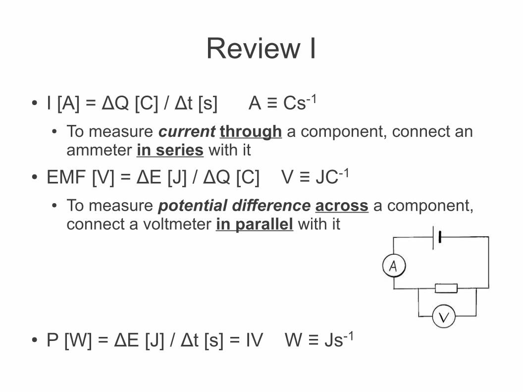
● I [A] = ΔQ [C] / Δt [s] A ≡ Cs-1
● To measure current through a component, connect an ammeter in series with it
● EMF [V] = ΔE [J] / ΔQ [C] V ≡ JC-1
● To measure potential difference across a component, connect a voltmeter in parallel with it
● P [W] = ΔE [J] / Δt [s] = IV W ≡ Js-1
Review II
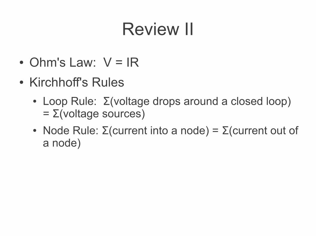
● Ohm's Law: V = IR● Kirchhoff's Rules
● Loop Rule: Σ(voltage drops around a closed loop) = Σ(voltage sources)
● Node Rule: Σ(current into a node) = Σ(current out of a node)
Review III
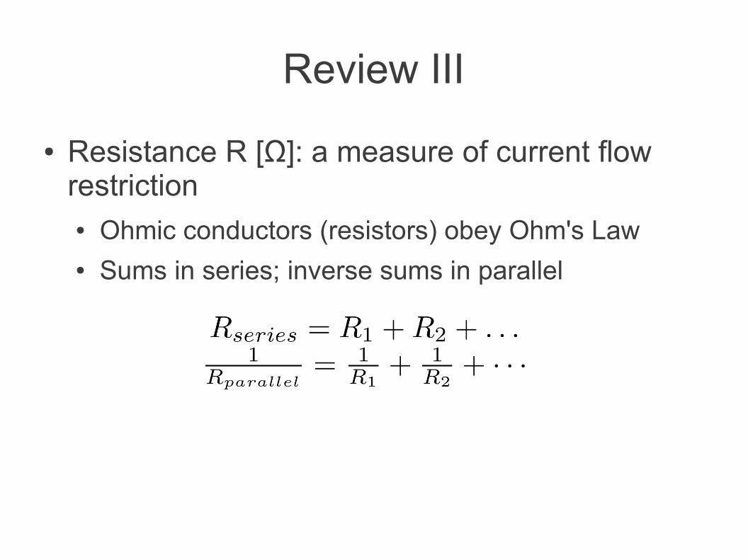
● Resistance R [Ω]: a measure of current flow restriction● Ohmic conductors (resistors) obey Ohm's Law● Sums in series; inverse sums in parallel
Review IV
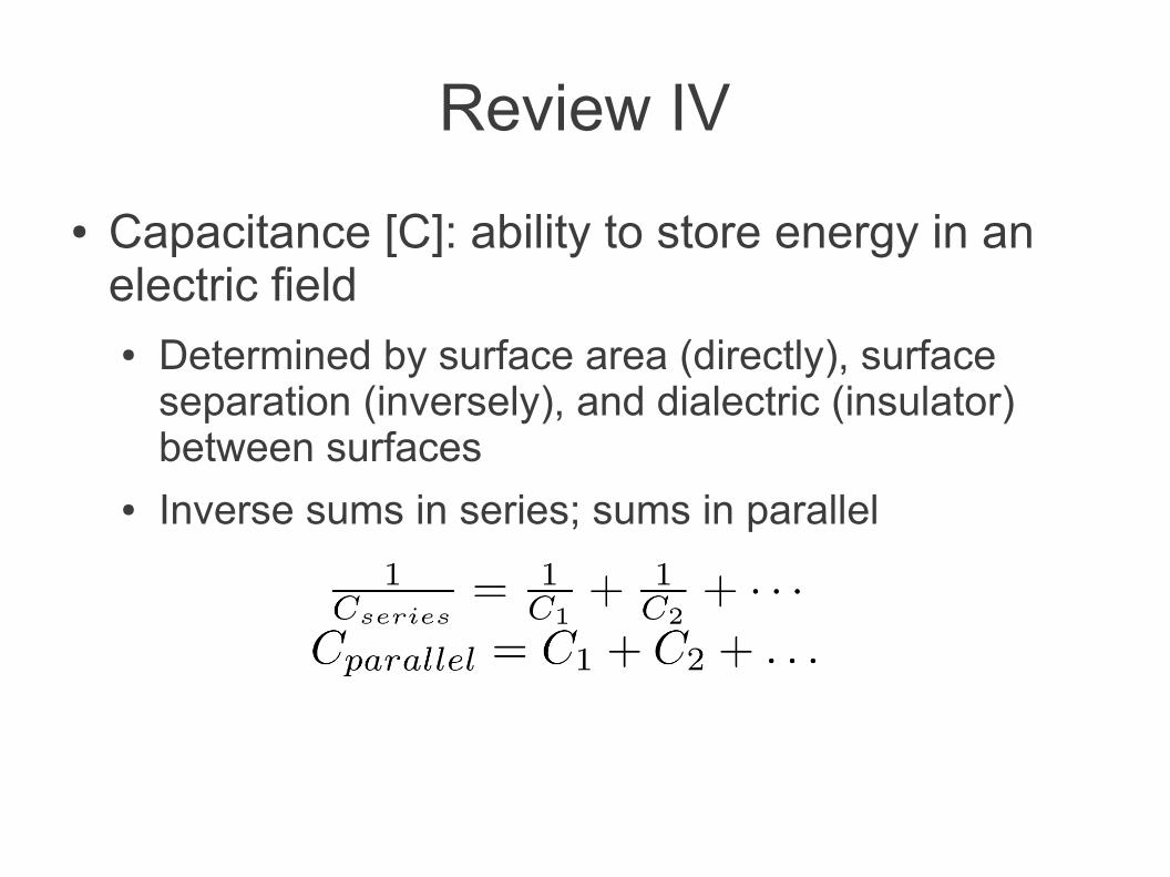
● Capacitance [C]: ability to store energy in an electric field● Determined by surface area (directly), surface
separation (inversely), and dialectric (insulator) between surfaces
● Inverse sums in series; sums in parallel
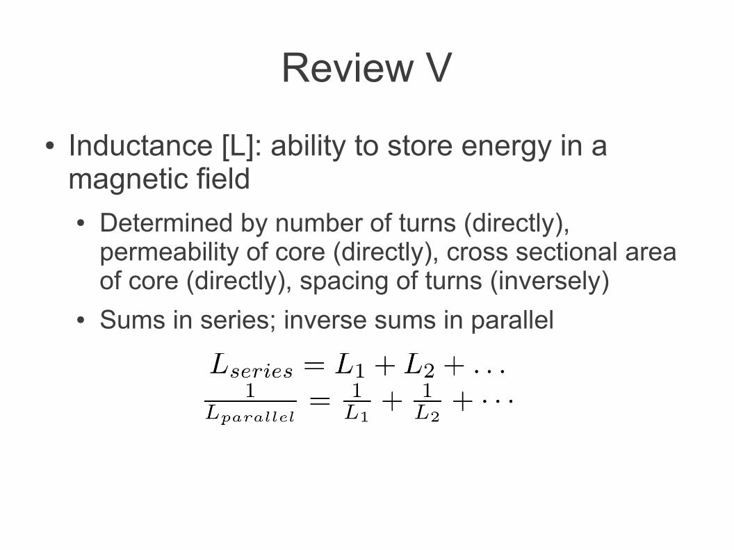
Review V
● Inductance [L]: ability to store energy in a magnetic field● Determined by number of turns (directly),
permeability of core (directly), cross sectional area of core (directly), spacing of turns (inversely)
● Sums in series; inverse sums in parallel
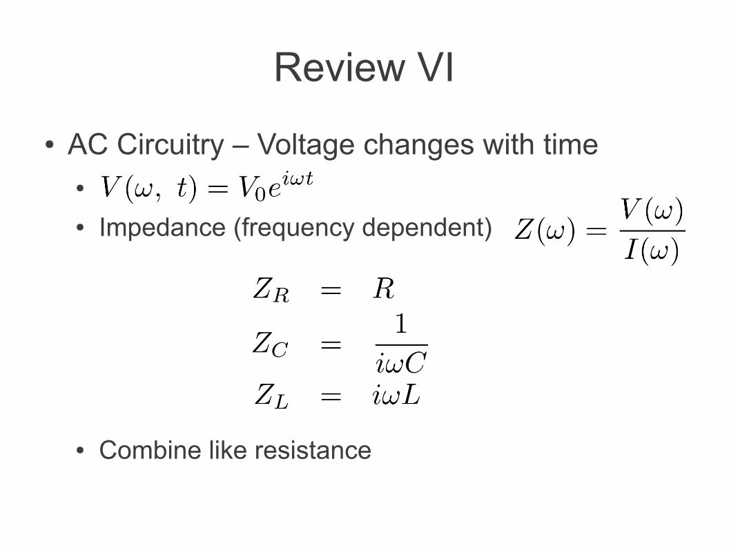
Review VI
● AC Circuitry – Voltage changes with time●
● Impedance (frequency dependent)
● Combine like resistance
Component Selection CriteriaChoosing the right type for the intended function● Nominal value and tolerance● Stability: Temperature, etc. / Environment● Interactions: Heating and out-gassing● Shape / Size● Power dissipation and voltage rating● Frequency characteristics● Derating● Cost

Linear (Ohmic) Components● Resistors
● Fixed● Variable
● Capacitors● Transmission Lines● Coaxial Connectors● Relays
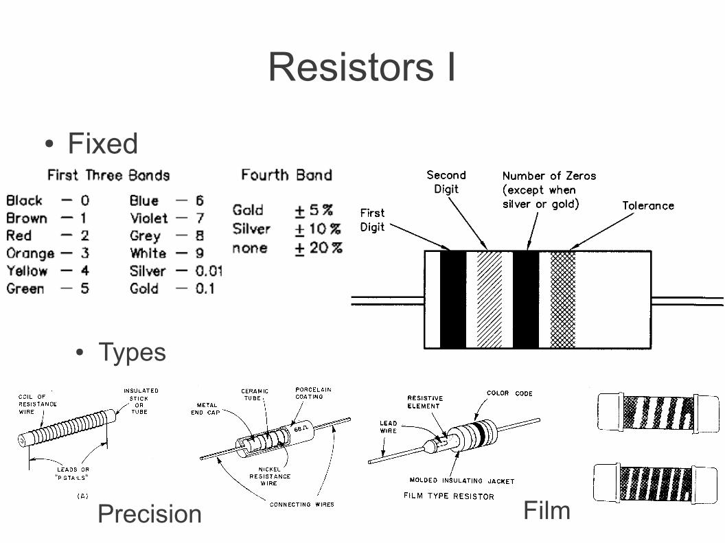
Resistors I
● Fixed
● Types
Precision Film
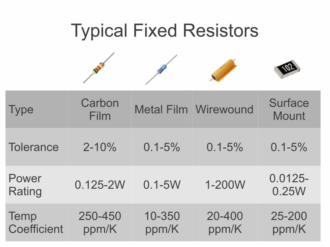
Typical Fixed Resistors
Type Carbon Film Metal Film Wirewound Surface
Mount
Tolerance 2-10% 0.1-5% 0.1-5% 0.1-5%
Power Rating 0.125-2W 0.1-5W 1-200W 0.0125-
0.25W
Temp Coefficient
250-450 ppm/K
10-350 ppm/K
20-400 ppm/K
25-200 ppm/K
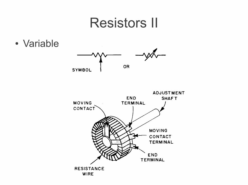
Resistors II● Variable
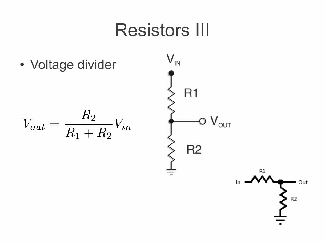
Resistors III
● Voltage divider
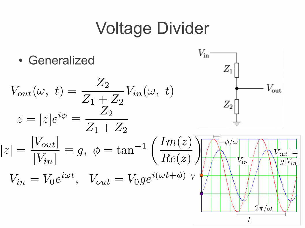
Voltage Divider
● Generalized
Capacitors I● Voltage Rating: Measured as DC (AC of same
value has peak voltages too high)● Polarized: must always have DC voltage, of
the correct polarity, exceeding any AC voltage
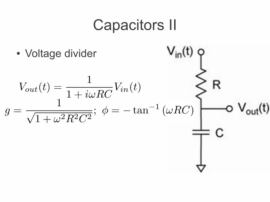
Capacitors II
● Voltage divider
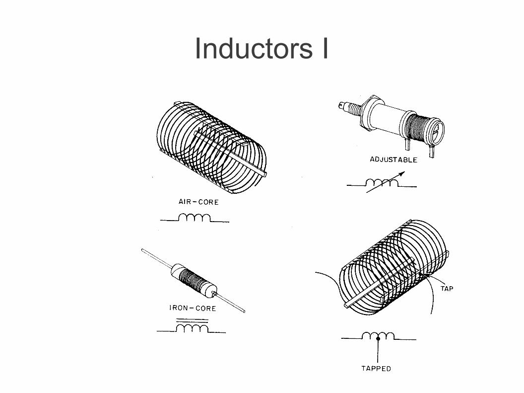
Inductors I
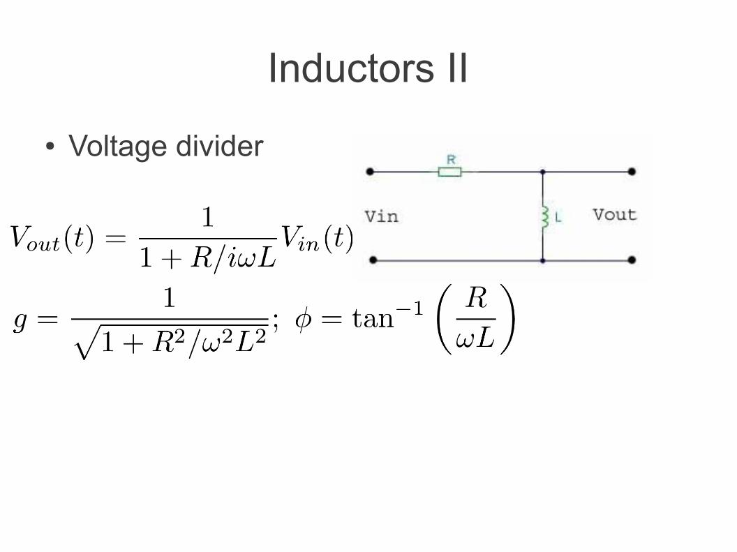
Inductors II
● Voltage divider
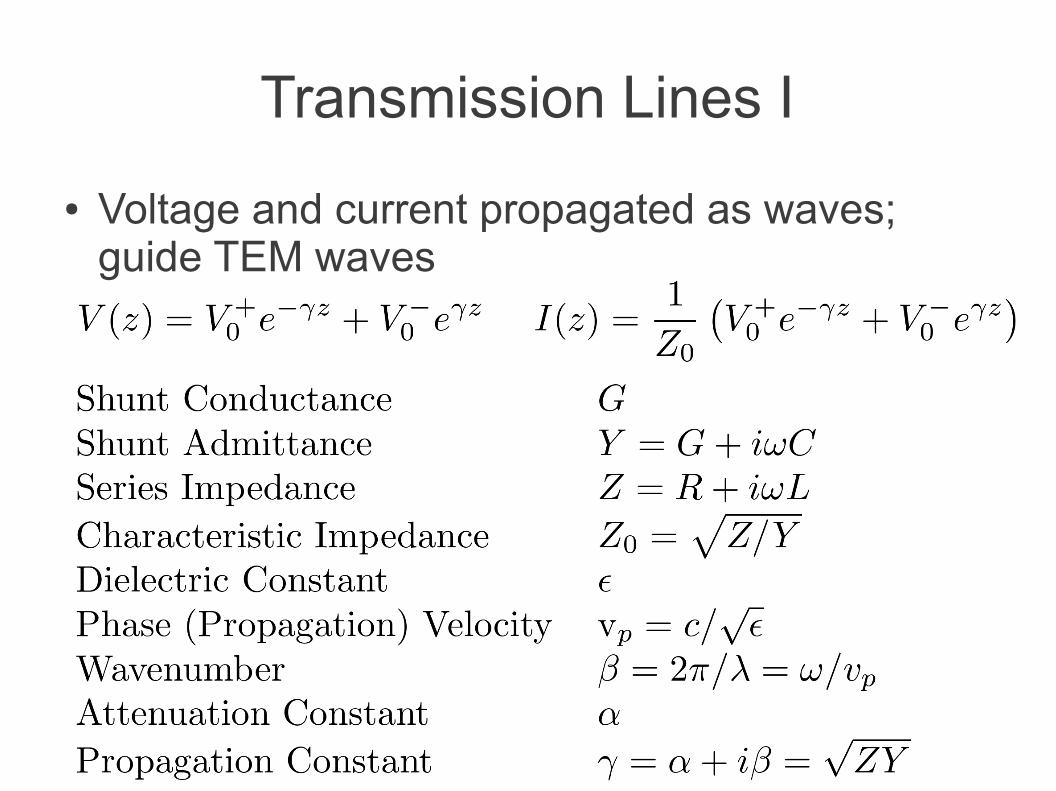
Transmission Lines I
● Voltage and current propagated as waves; guide TEM waves
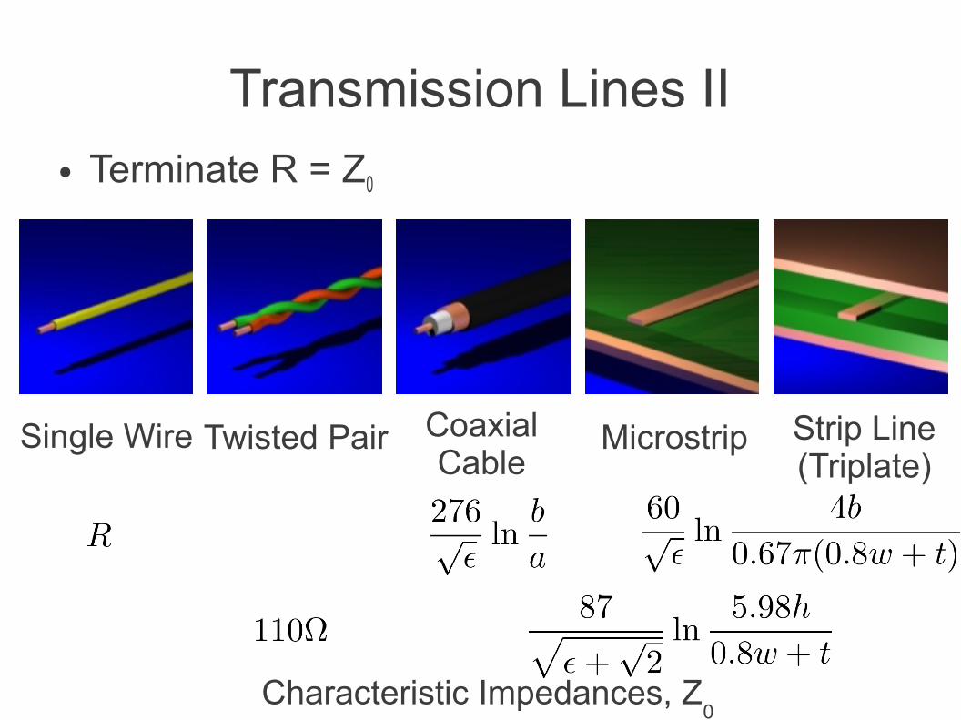
Transmission Lines II● Terminate R = Z0
Single Wire Twisted Pair CoaxialCable
Microstrip Strip Line(Triplate)
Characteristic Impedances, Z0
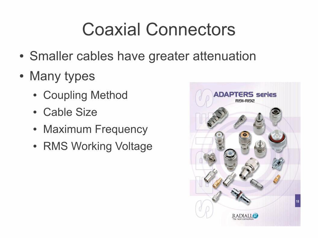
Coaxial Connectors● Smaller cables have greater attenuation● Many types
● Coupling Method● Cable Size● Maximum Frequency● RMS Working Voltage

Relays
● Electrically actuated (electromechanical or solid-state) switches● Operating voltage● Power rating● Contact current rating● Speed● Noise● Contact conditioning
Non-Linear Components
● Band Theory of Solids● Semiconductors● Diodes● Transistors● Thyristors
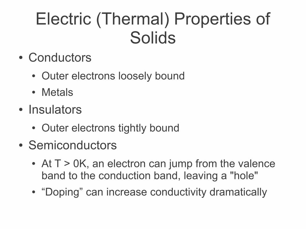
Electric (Thermal) Properties of Solids
● Conductors● Outer electrons loosely bound● Metals
● Insulators● Outer electrons tightly bound
● Semiconductors● At T > 0K, an electron can jump from the valence
band to the conduction band, leaving a "hole"● “Doping” can increase conductivity dramatically
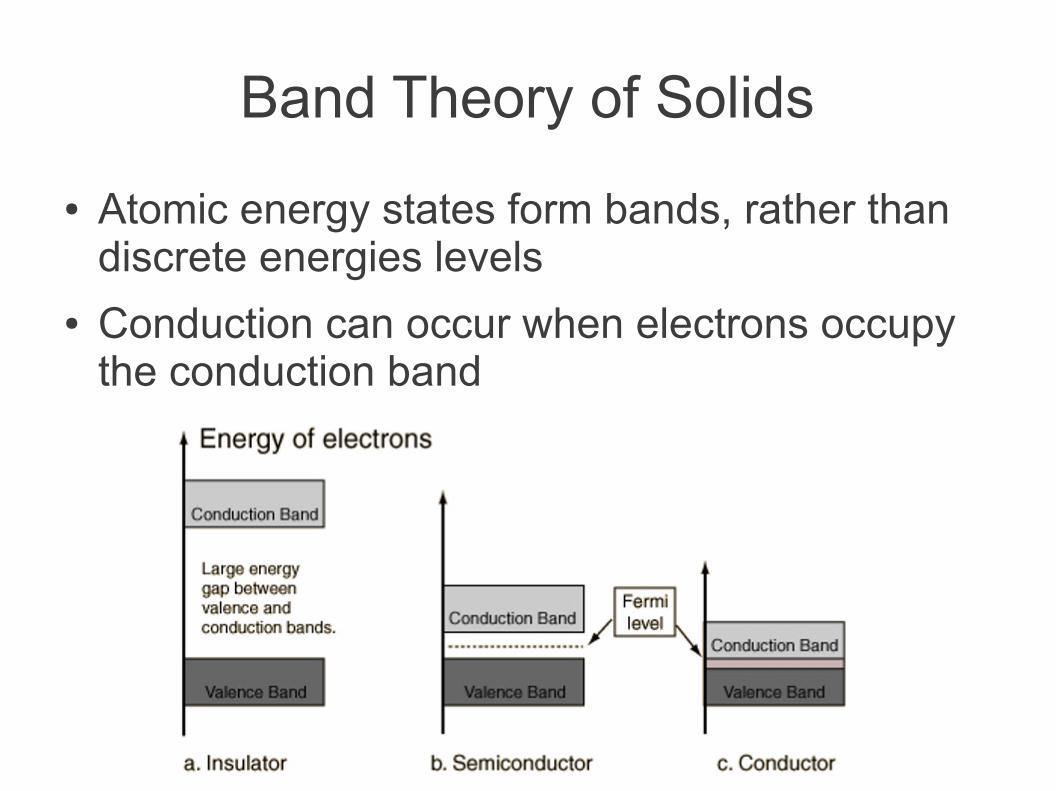
Band Theory of Solids
● Atomic energy states form bands, rather than discrete energies levels
● Conduction can occur when electrons occupy the conduction band
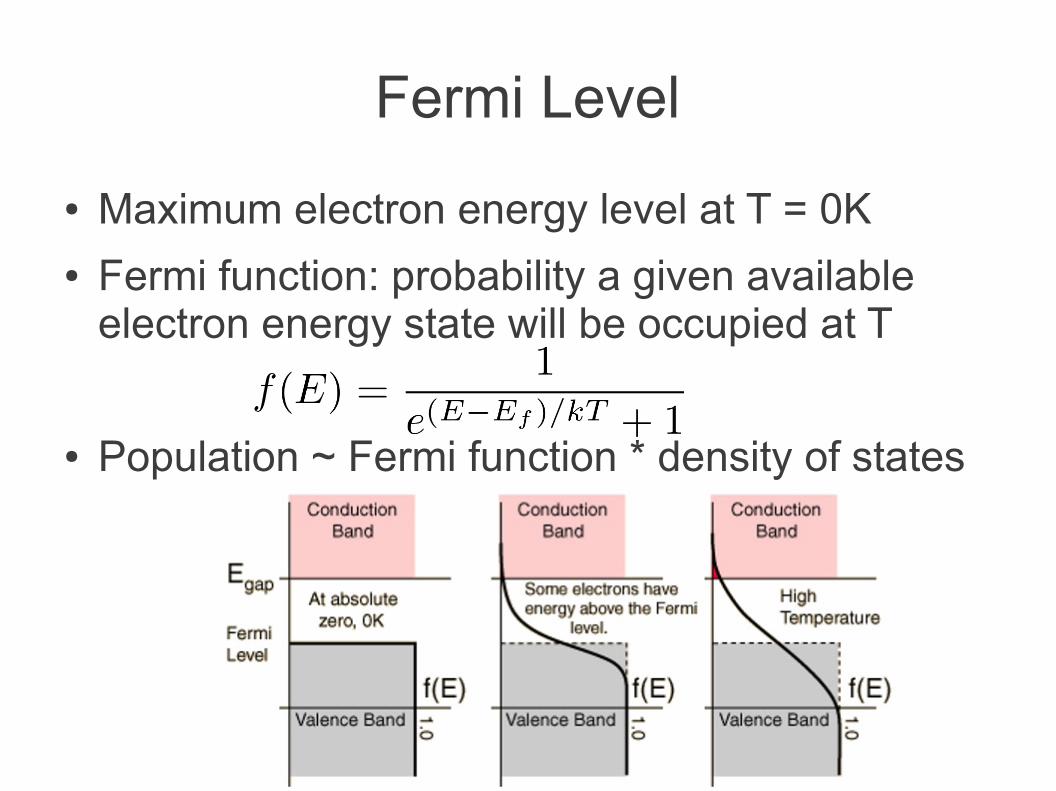
Fermi Level
● Maximum electron energy level at T = 0K● Fermi function: probability a given available
electron energy state will be occupied at T
● Population ~ Fermi function * density of states
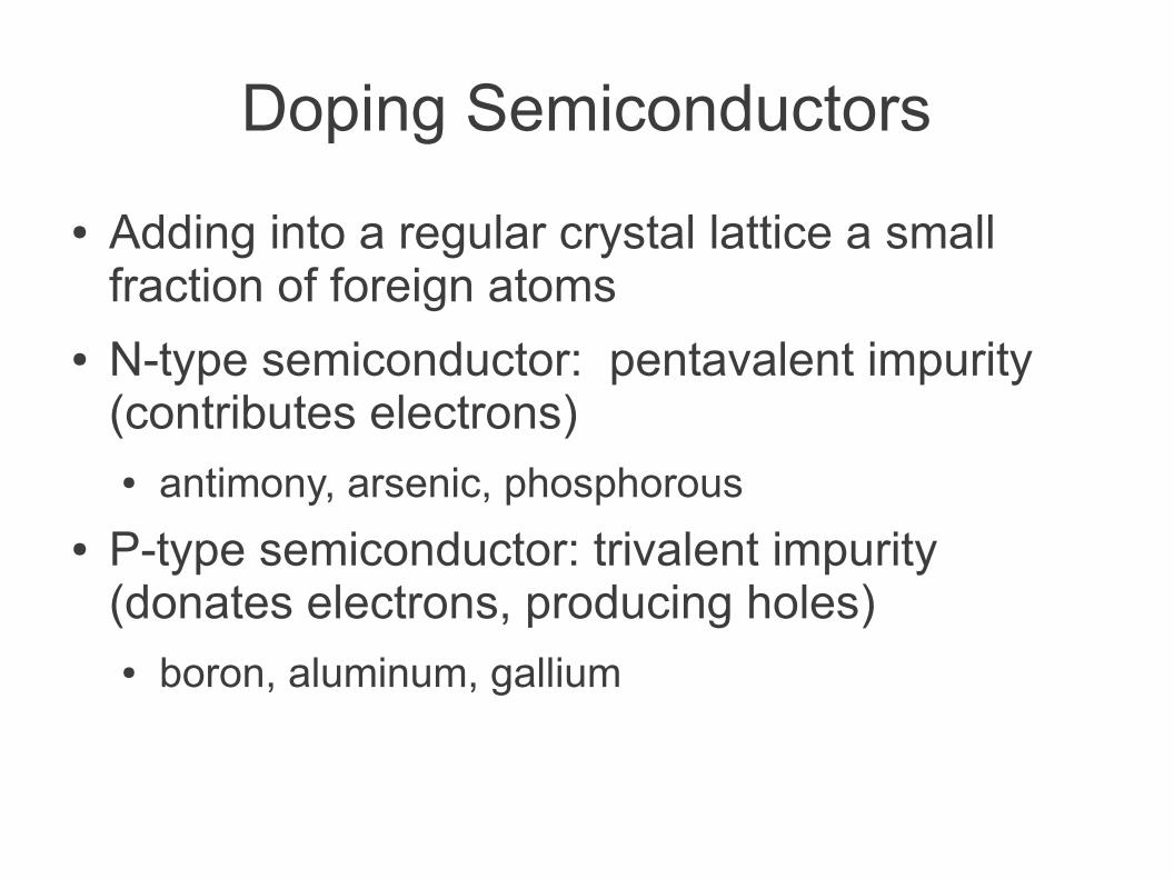
Doping Semiconductors
● Adding into a regular crystal lattice a small fraction of foreign atoms
● N-type semiconductor: pentavalent impurity (contributes electrons)● antimony, arsenic, phosphorous
● P-type semiconductor: trivalent impurity (donates electrons, producing holes)● boron, aluminum, gallium
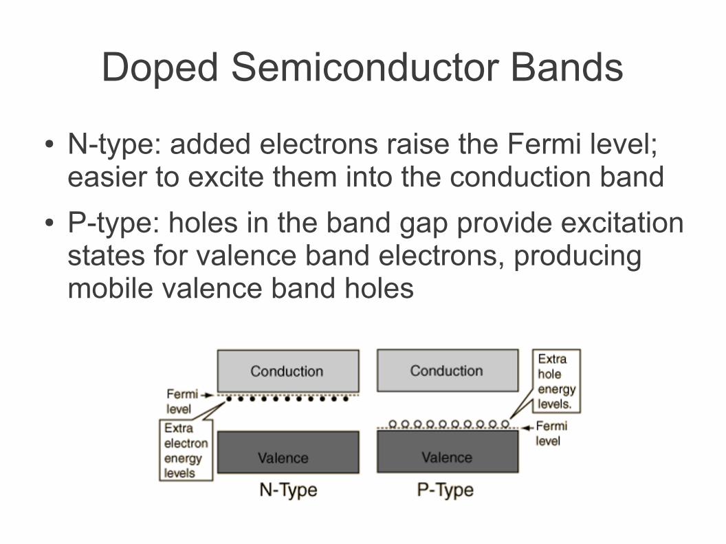
Doped Semiconductor Bands
● N-type: added electrons raise the Fermi level; easier to excite them into the conduction band
● P-type: holes in the band gap provide excitation states for valence band electrons, producing mobile valence band holes
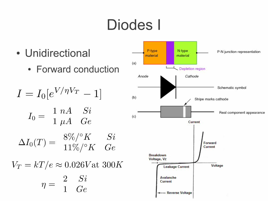
Diodes I
● Unidirectional● Forward conduction
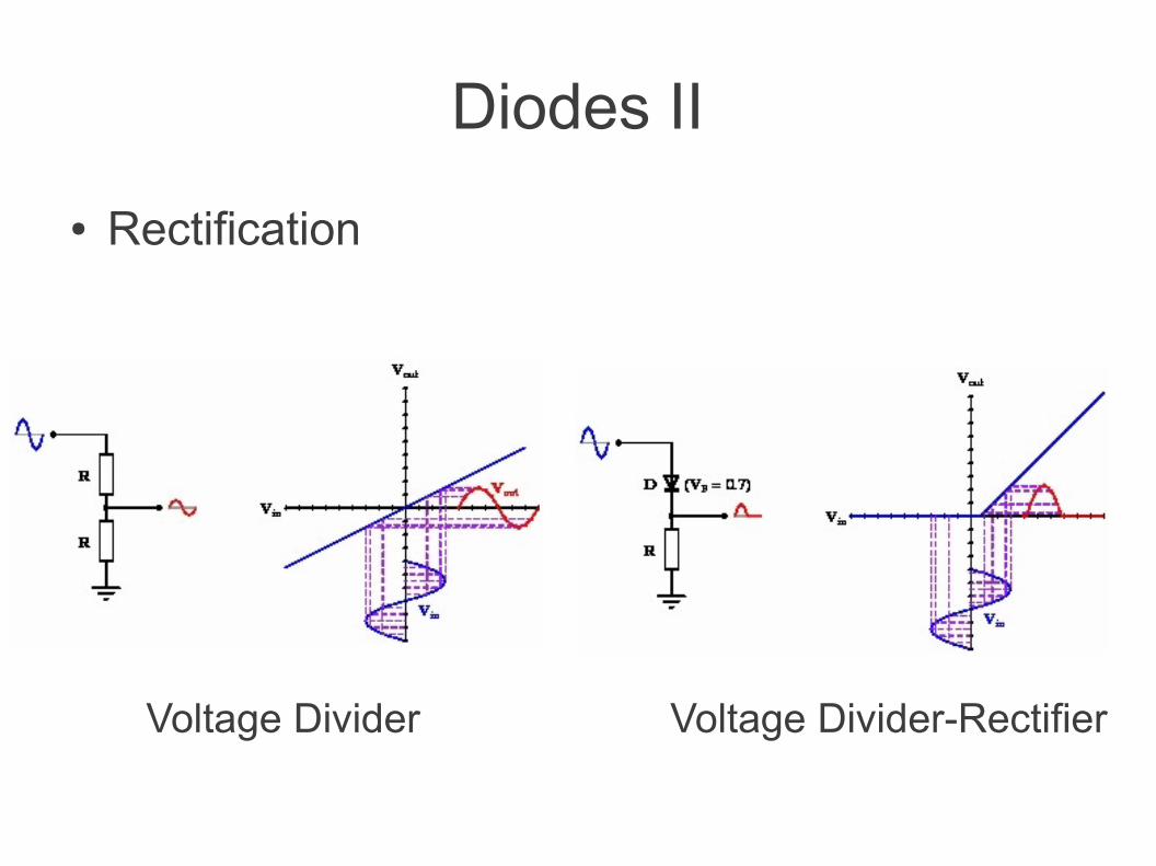
Diodes II
● Rectification
Voltage Divider Voltage Divider-Rectifier
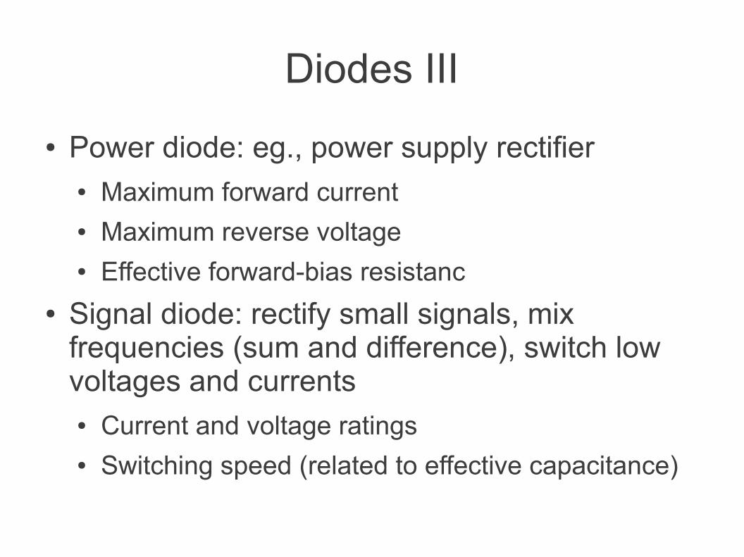
Diodes III
● Power diode: eg., power supply rectifier● Maximum forward current● Maximum reverse voltage● Effective forward-bias resistanc
● Signal diode: rectify small signals, mix frequencies (sum and difference), switch low voltages and currents● Current and voltage ratings● Switching speed (related to effective capacitance)
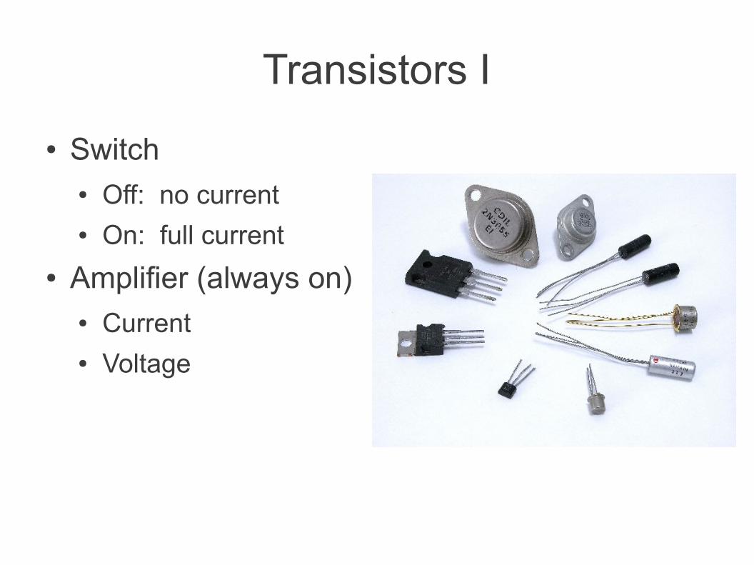
Transistors I
● Switch● Off: no current● On: full current
● Amplifier (always on)● Current● Voltage
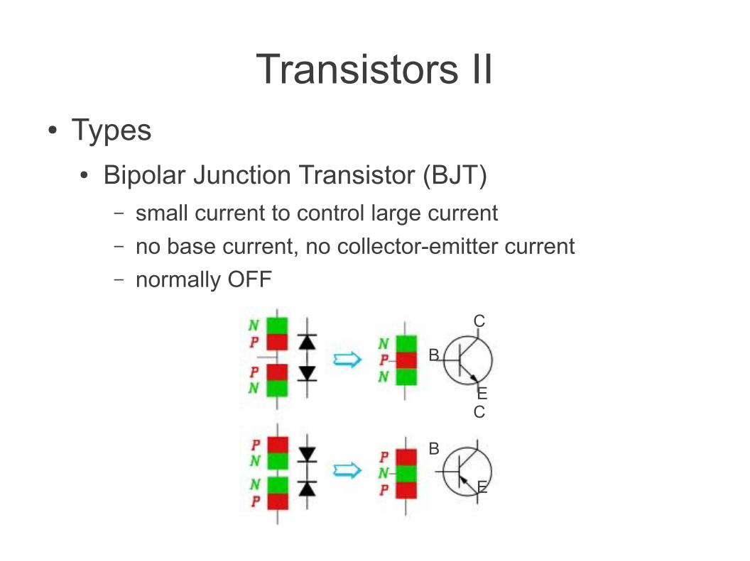
Transistors II● Types
● Bipolar Junction Transistor (BJT)– small current to control large current– no base current, no collector-emitter current– normally OFF
B
C
E
CE
B
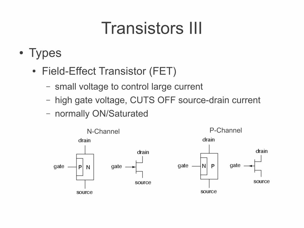
Transistors III● Types
● Field-Effect Transistor (FET)– small voltage to control large current– high gate voltage, CUTS OFF source-drain current– normally ON/Saturated
P-ChannelN-Channel
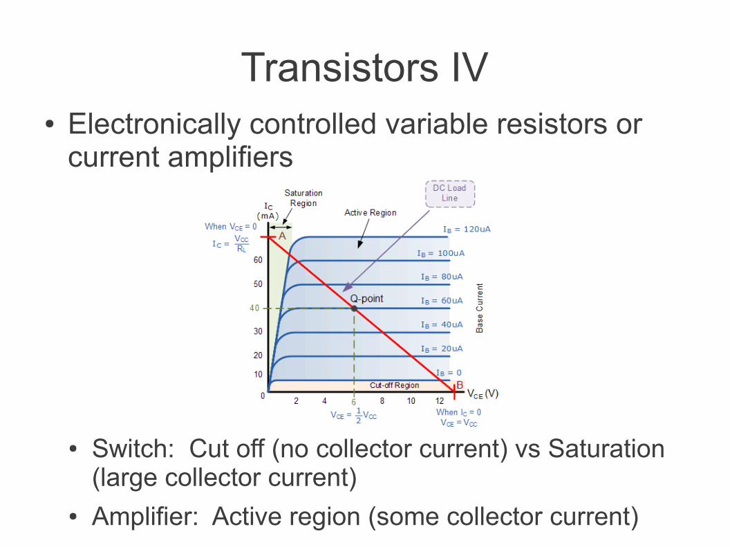
Transistors IV● Electronically controlled variable resistors or
current amplifiers
● Switch: Cut off (no collector current) vs Saturation (large collector current)
● Amplifier: Active region (some collector current)
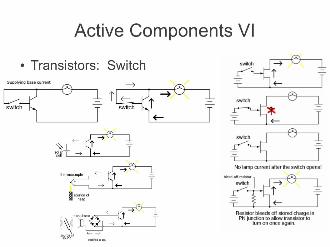
Active Components VI
● Transistors: Switch
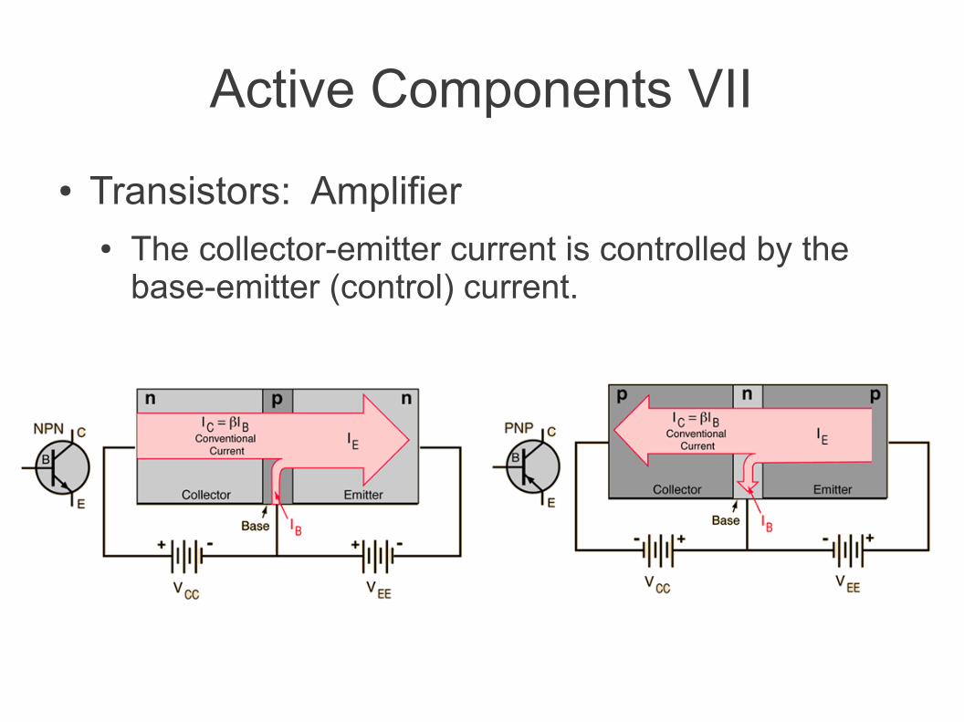
Active Components VII
● Transistors: Amplifier● The collector-emitter current is controlled by the
base-emitter (control) current.
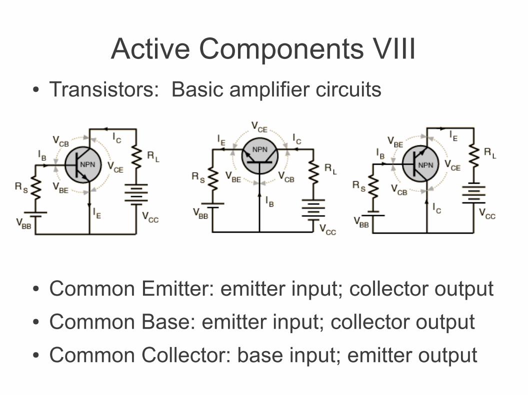
Active Components VIII● Transistors: Basic amplifier circuits
● Common Emitter: emitter input; collector output● Common Base: emitter input; collector output● Common Collector: base input; emitter output
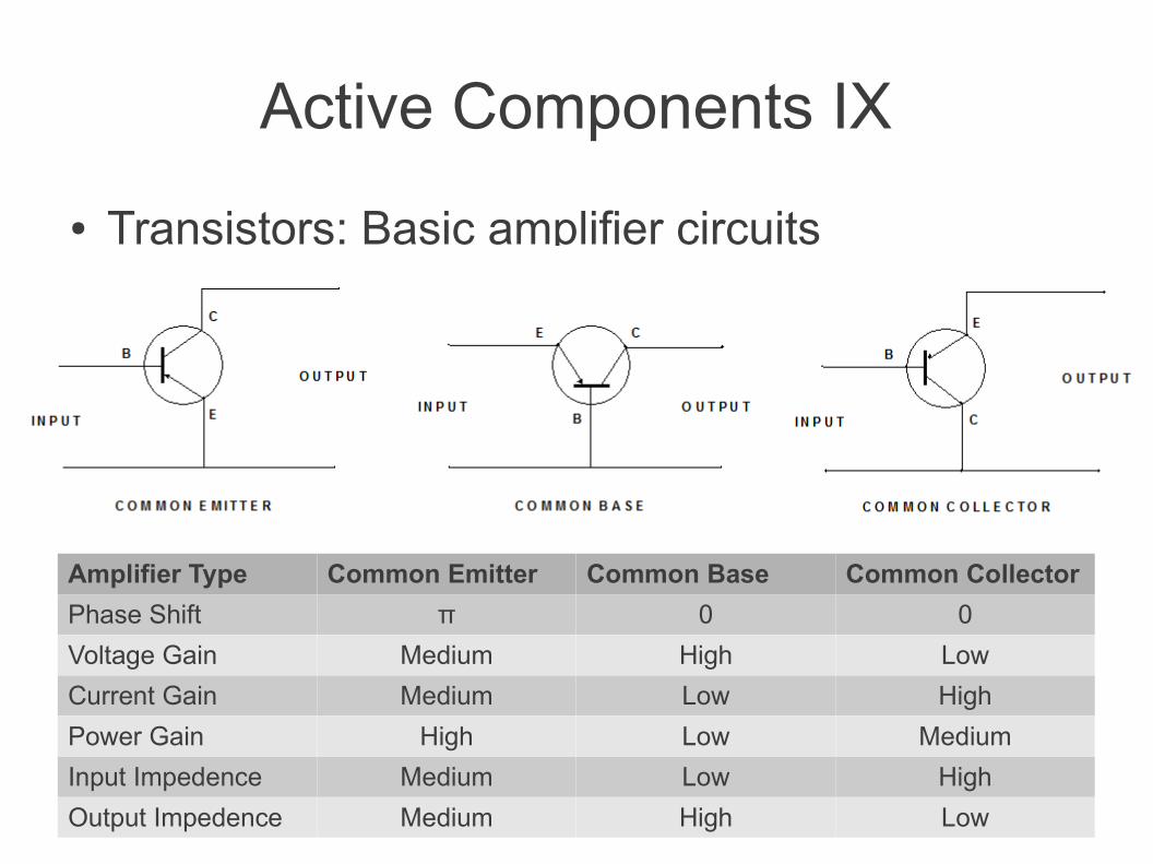
Active Components IX
● Transistors: Basic amplifier circuits
Amplifier Type Common Emitter Common Base Common Collector
Phase Shift π 0 0
Voltage Gain Medium High Low
Current Gain Medium Low High
Power Gain High Low Medium
Input Impedence Medium Low High
Output Impedence Medium High Low
Active Components X
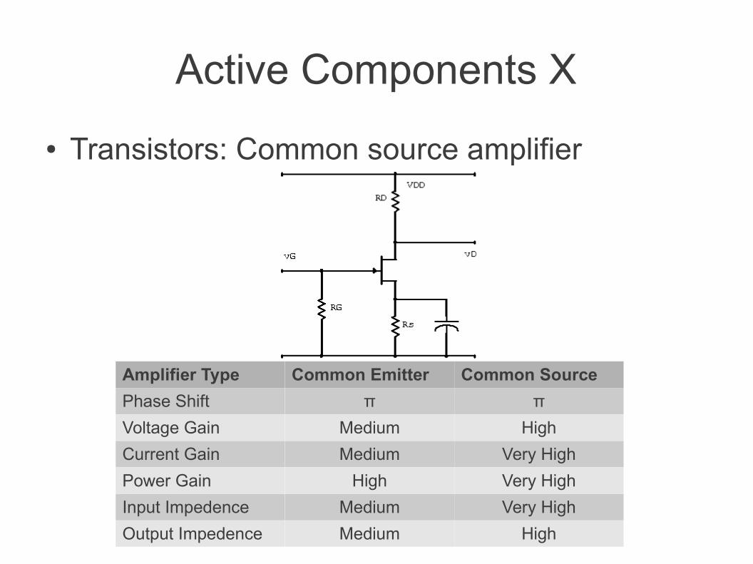
● Transistors: Common source amplifier
Amplifier Type Common Emitter Common Source
Phase Shift π π
Voltage Gain Medium High
Current Gain Medium Very High
Power Gain High Very High
Input Impedence Medium Very High
Output Impedence Medium High
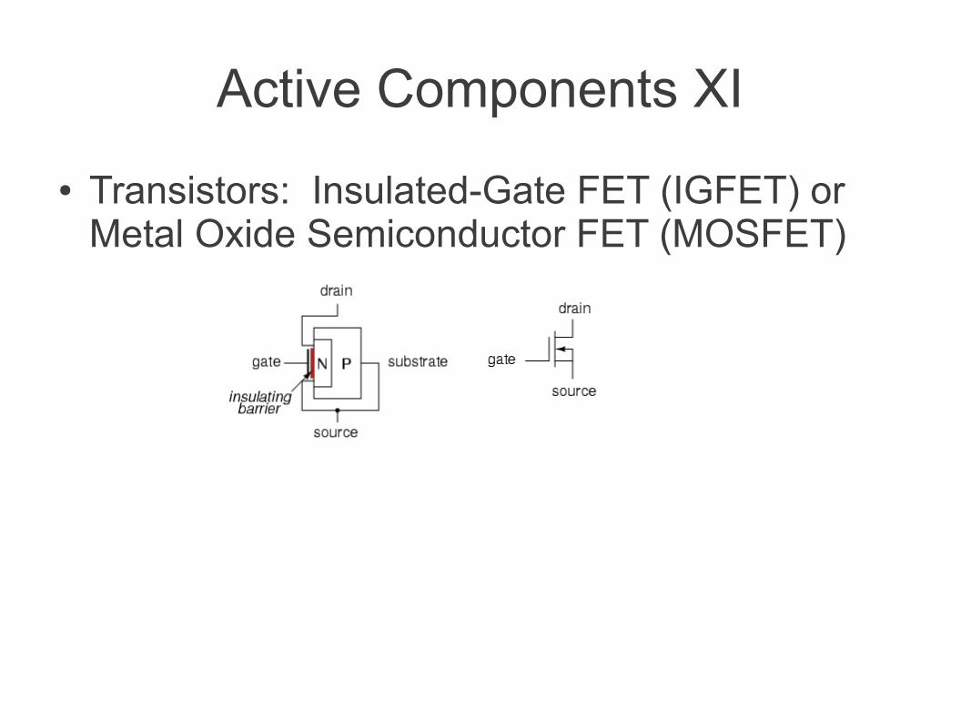
Active Components XI
● Transistors: Insulated-Gate FET (IGFET) or Metal Oxide Semiconductor FET (MOSFET)
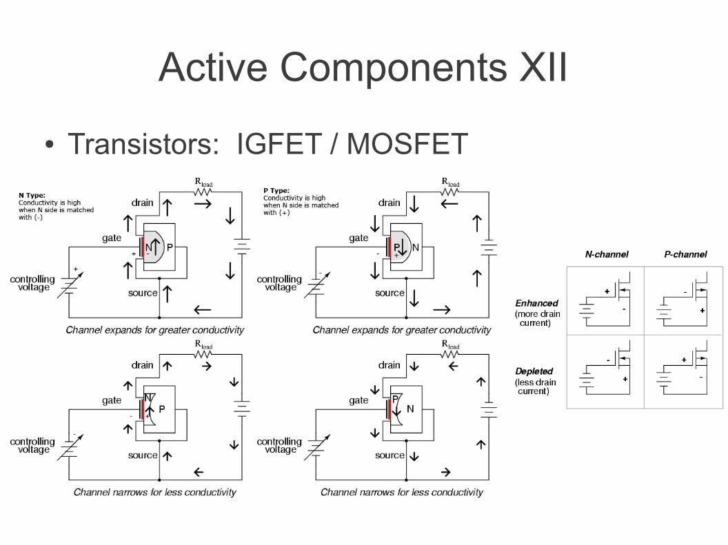
Active Components XII
● Transistors: IGFET / MOSFET
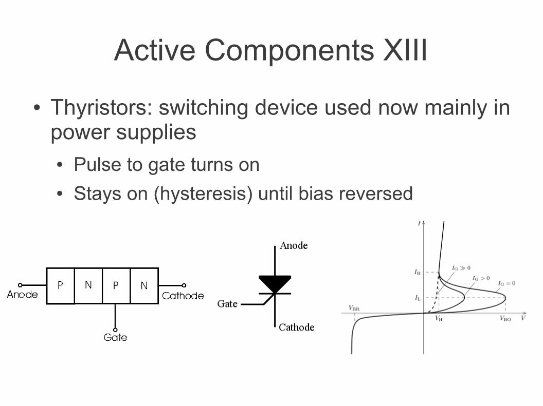
Active Components XIII
● Thyristors: switching device used now mainly in power supplies● Pulse to gate turns on● Stays on (hysteresis) until bias reversed
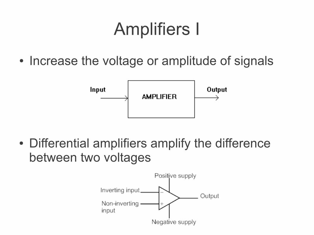
Amplifiers I
● Increase the voltage or amplitude of signals
● Differential amplifiers amplify the difference between two voltages
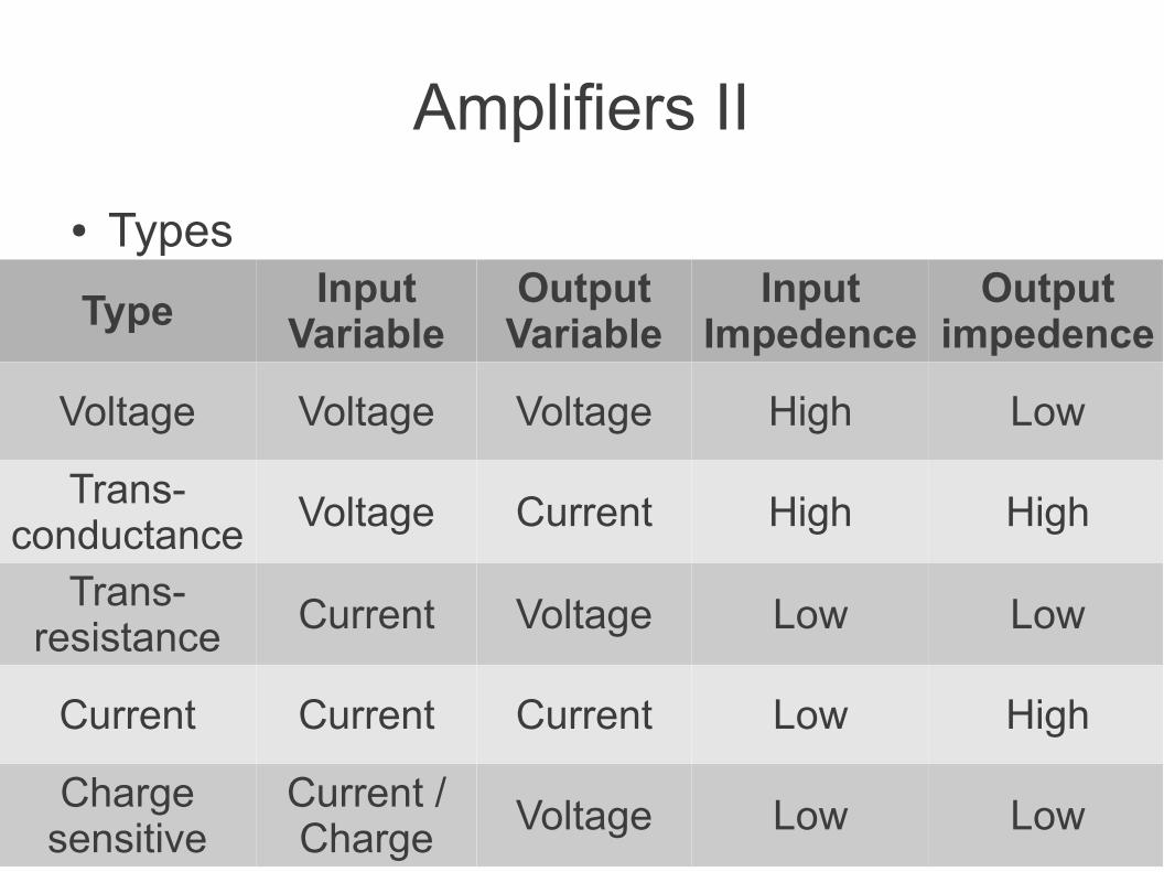
Amplifiers II
● Types
Type Input Variable
Output Variable
Input Impedence
Output impedence
Voltage Voltage Voltage High Low
Trans-conductance Voltage Current High High
Trans-resistance Current Voltage Low Low
Current Current Current Low High
Charge sensitive
Current / Charge Voltage Low Low
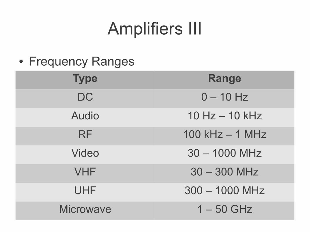
Amplifiers III
● Frequency RangesType Range
DC 0 – 10 Hz
Audio 10 Hz – 10 kHz
RF 100 kHz – 1 MHz
Video 30 – 1000 MHz
VHF 30 – 300 MHz
UHF 300 – 1000 MHz
Microwave 1 – 50 GHz
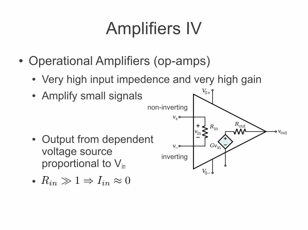
Amplifiers IV
● Operational Amplifiers (op-amps)● Very high input impedence and very high gain● Amplify small signals
● Output from dependent voltage source proportional to Vin
●
non-inverting
inverting
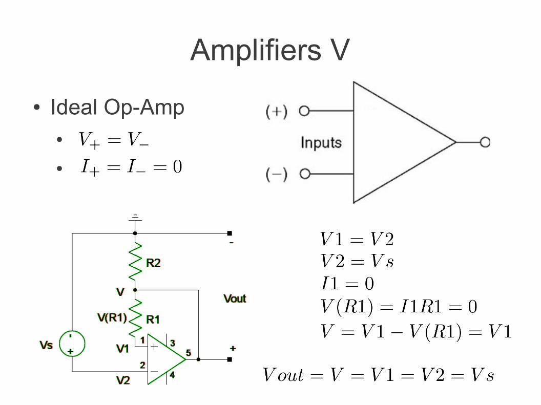
Amplifiers V
● Ideal Op-Amp●
●
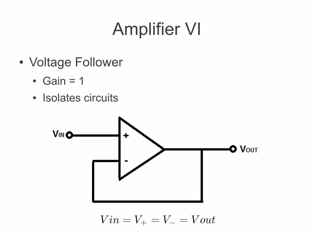
Amplifier VI
● Voltage Follower● Gain = 1● Isolates circuits
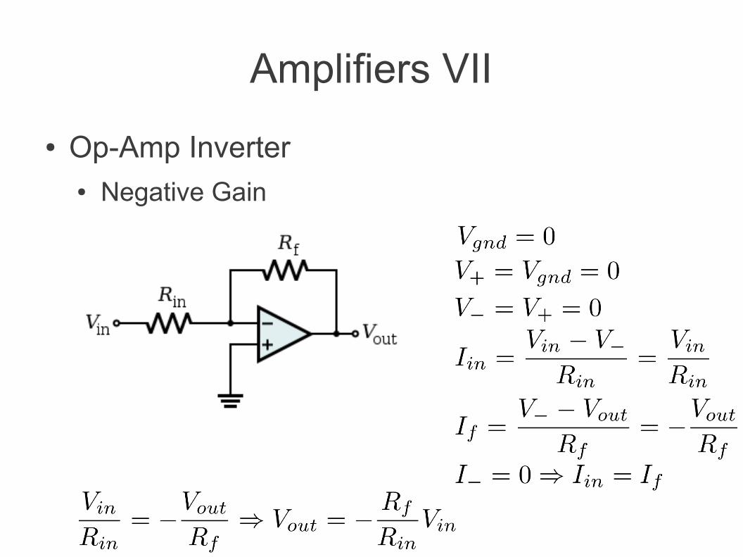
Amplifiers VII
● Op-Amp Inverter● Negative Gain
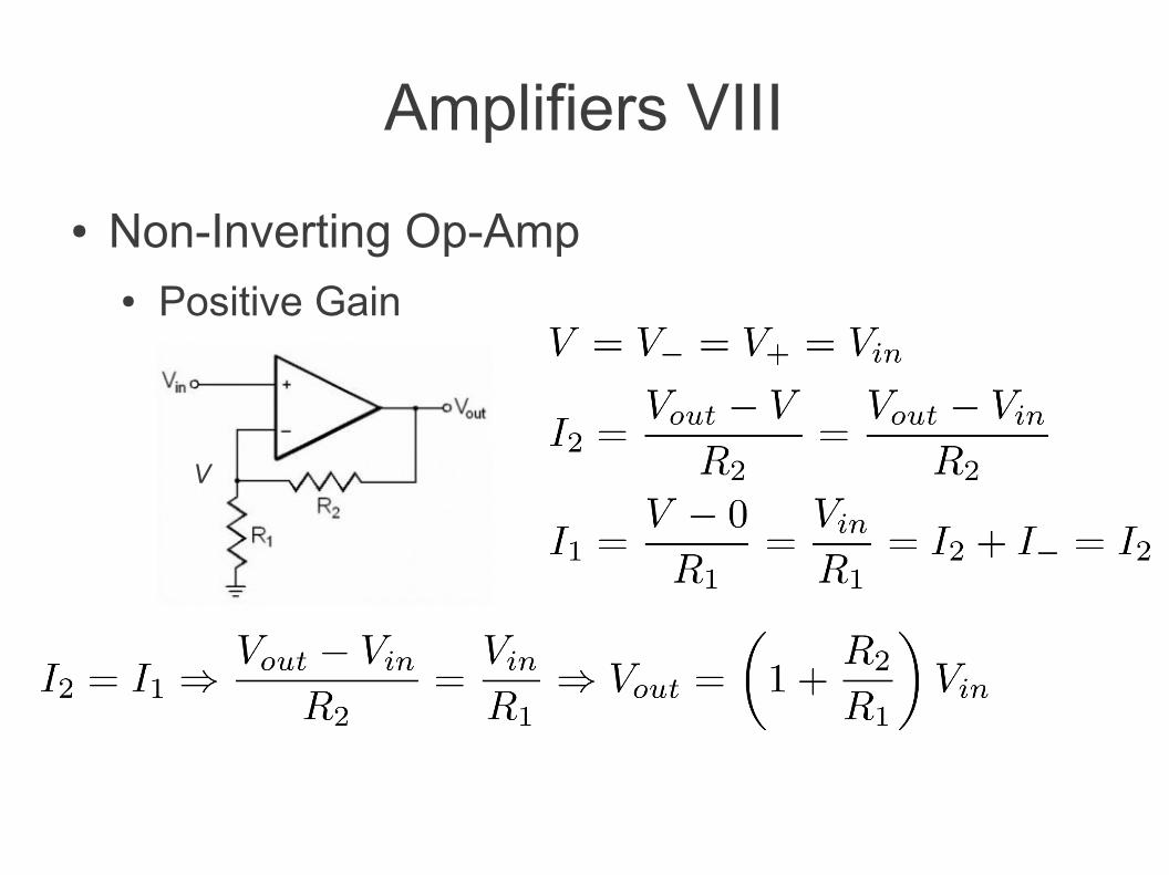
Amplifiers VIII
● Non-Inverting Op-Amp● Positive Gain
V
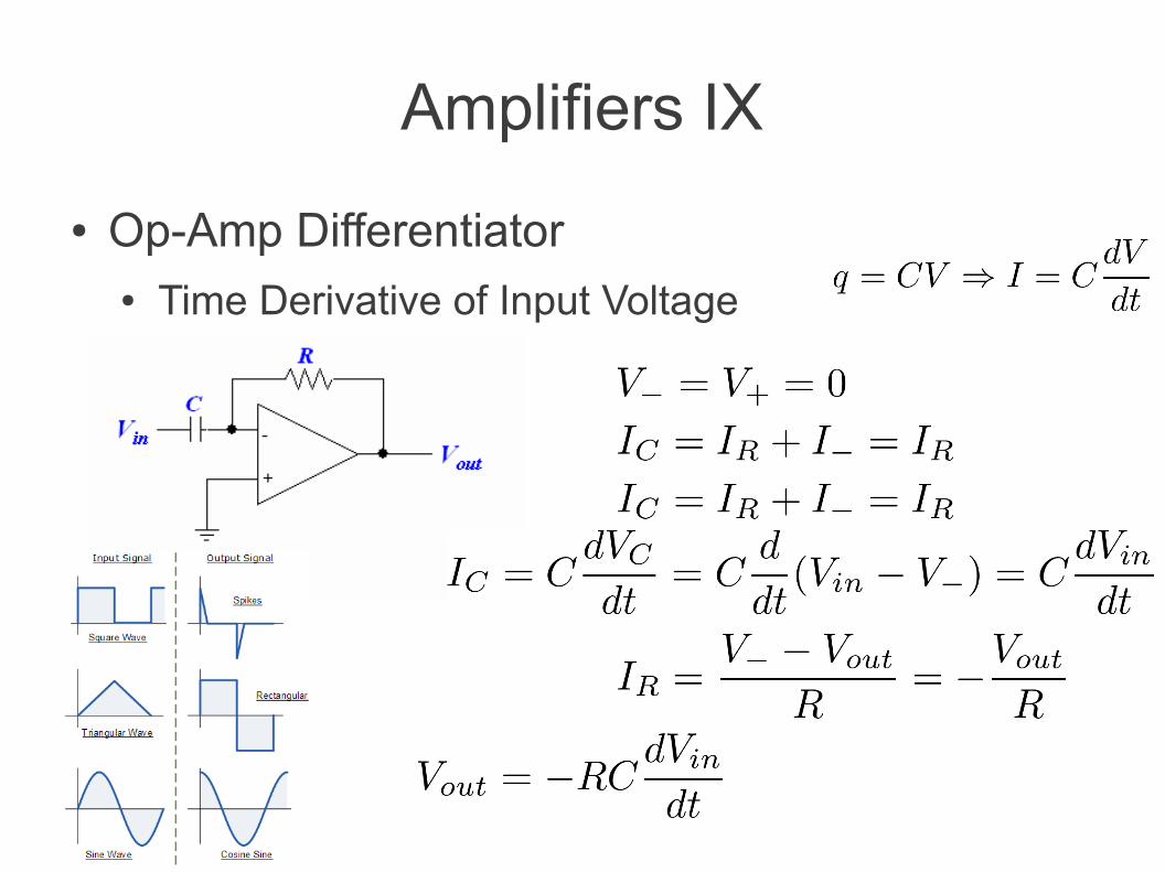
Amplifiers IX
● Op-Amp Differentiator● Time Derivative of Input Voltage
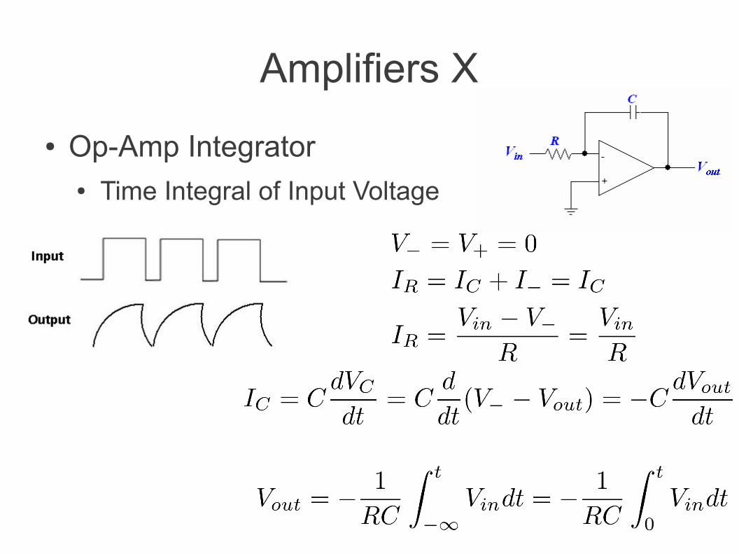
Amplifiers X
● Op-Amp Integrator● Time Integral of Input Voltage
Power Supplies I
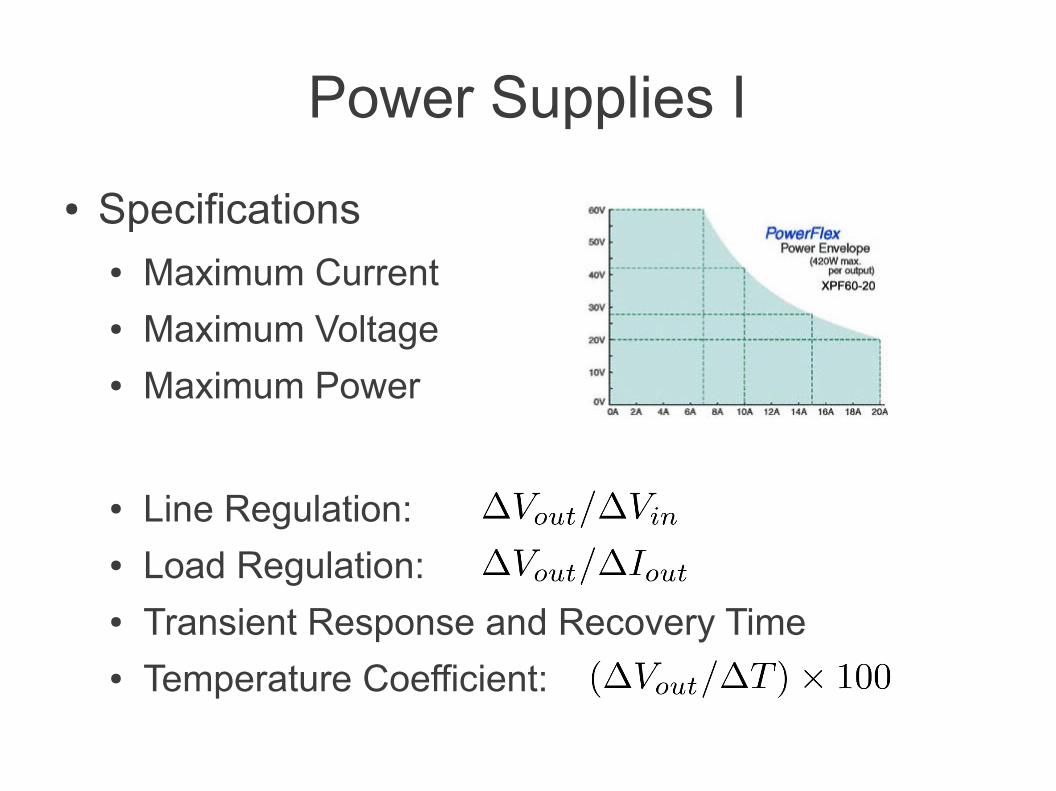
● Specifications● Maximum Current● Maximum Voltage● Maximum Power
● Line Regulation:● Load Regulation:● Transient Response and Recovery Time● Temperature Coefficient:
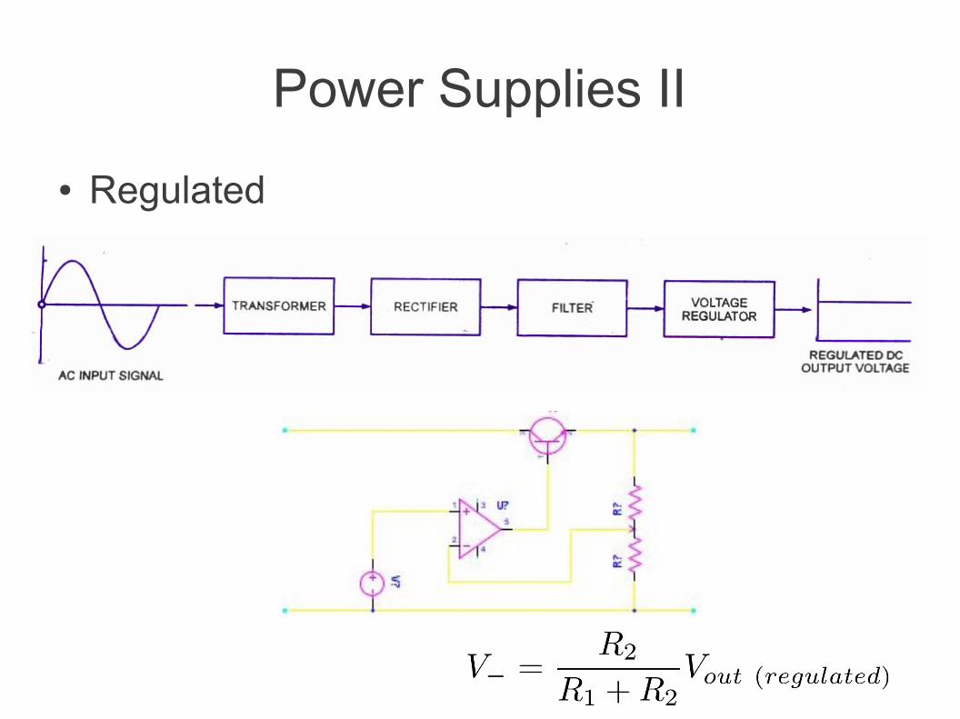
Power Supplies II
● Regulated
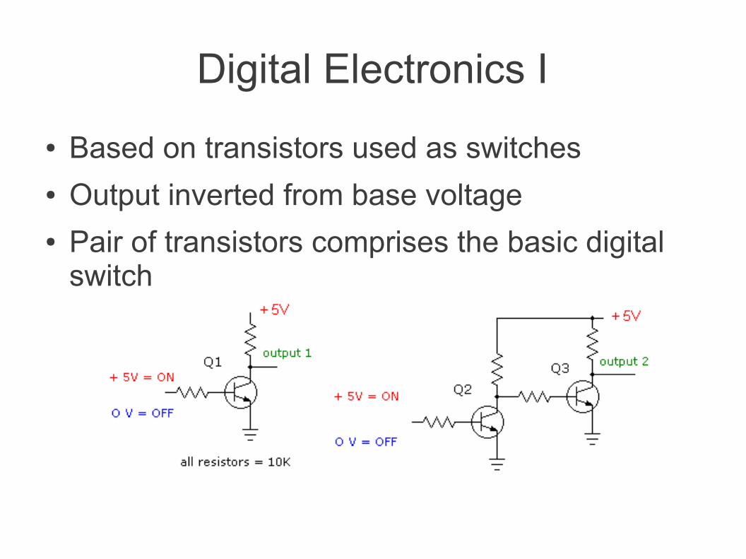
Digital Electronics I
● Based on transistors used as switches● Output inverted from base voltage● Pair of transistors comprises the basic digital
switch
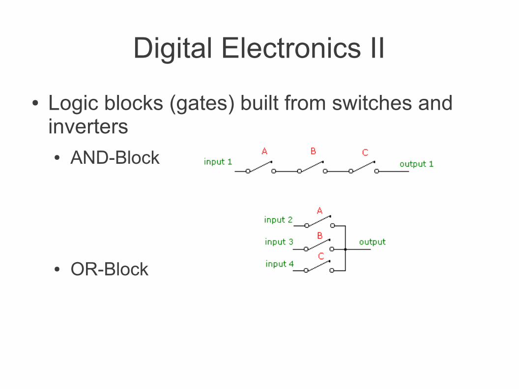
Digital Electronics II
● Logic blocks (gates) built from switches and inverters● AND-Block
● OR-Block
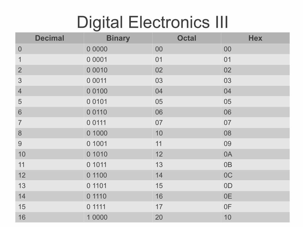
Digital Electronics IIIDecimal Binary Octal Hex
0 0 0000 00 00
1 0 0001 01 01
2 0 0010 02 02
3 0 0011 03 03
4 0 0100 04 04
5 0 0101 05 05
6 0 0110 06 06
7 0 0111 07 07
8 0 1000 10 08
9 0 1001 11 09
10 0 1010 12 0A
11 0 1011 13 0B
12 0 1100 14 0C
13 0 1101 15 0D
14 0 1110 16 0E
15 0 1111 17 0F
16 1 0000 20 10
Digital Electronics IV
● Bit: single binary digit (0 or 1)● Word: group of bits (represent a number)● Byte: eight-bit word● Bus – array of conductors for transferring
information within the computer.● Baud - bits/second
Digital Electronics V
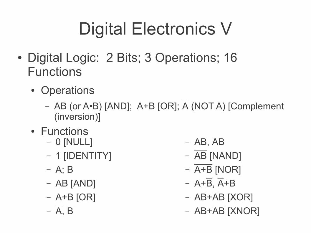
– 0 [NULL]– 1 [IDENTITY]– A; B– AB [AND]– A+B [OR]– A, B
● Digital Logic: 2 Bits; 3 Operations; 16 Functions● Operations
– AB (or A•B) [AND]; A+B [OR]; A (NOT A) [Complement (inversion)]
● Functions– AB, AB– AB [NAND]– A+B [NOR]– A+B, A+B– AB+AB [XOR]– AB+AB [XNOR]
Digital Electronics VI
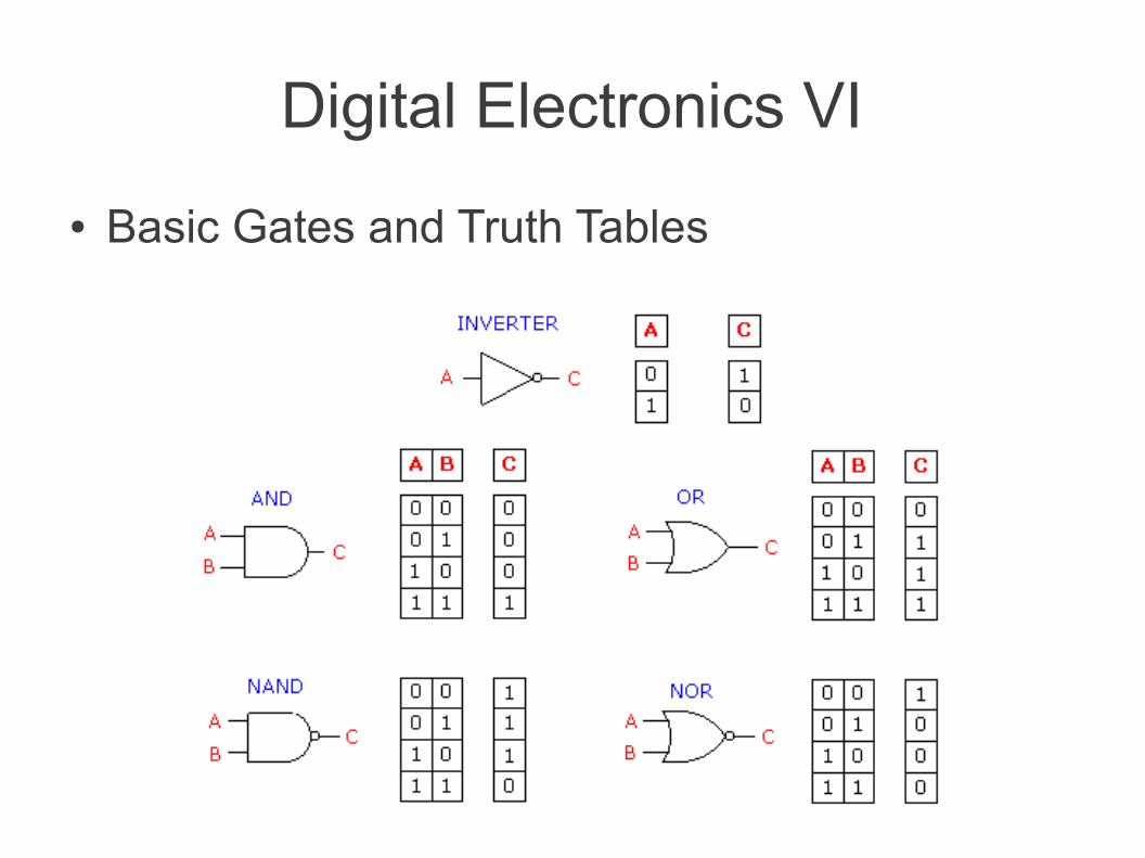
● Basic Gates and Truth Tables
Digital Electronics VII
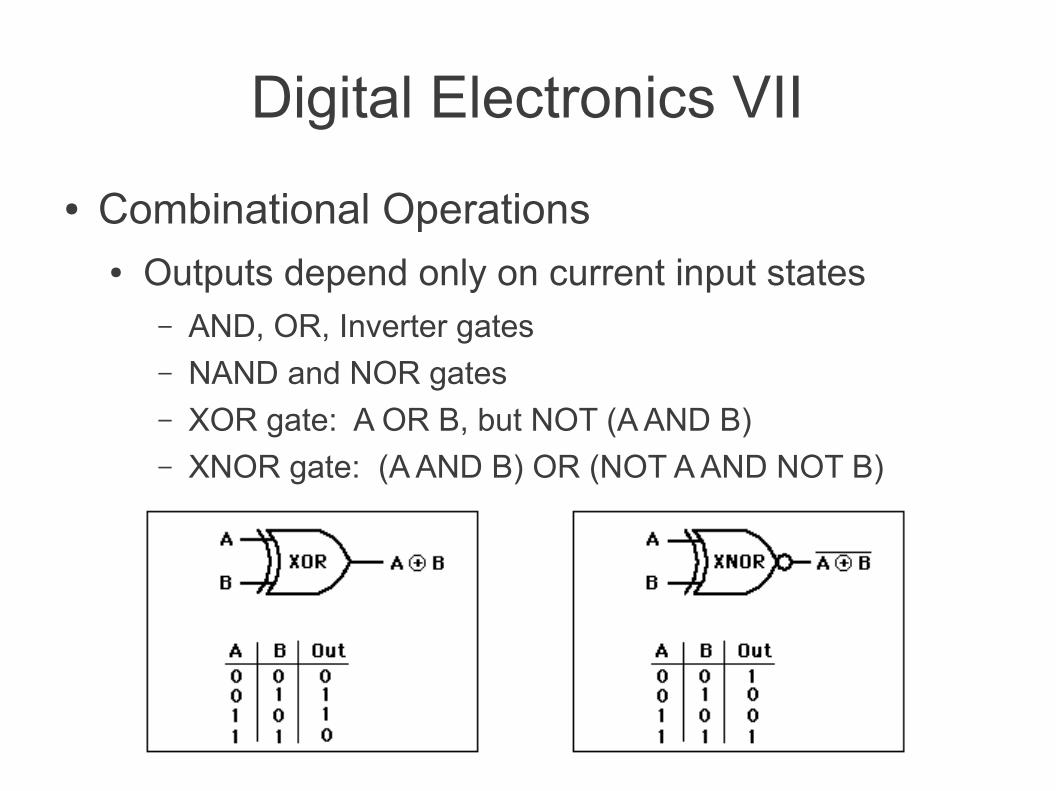
● Combinational Operations● Outputs depend only on current input states
– AND, OR, Inverter gates– NAND and NOR gates– XOR gate: A OR B, but NOT (A AND B)– XNOR gate: (A AND B) OR (NOT A AND NOT B)
Digital Electronics VIII
● Sequential Operations● Carried out by two-state devices (multivibrators)
– Bistable (flip-flop)– Astable– Monostable (one-shot)
Digital Electronics IX
● Flip-flops (Bistable Multivibrator)● Digital data storage and transfer● Registers
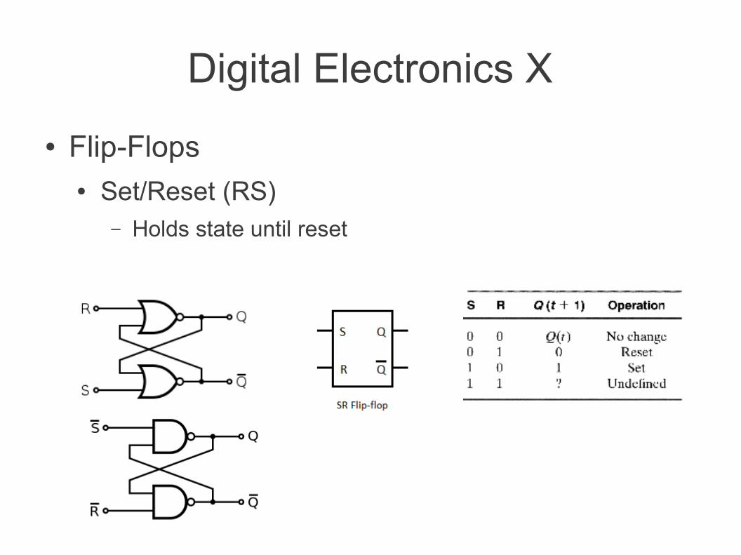
Digital Electronics X
● Flip-Flops● Set/Reset (RS)
– Holds state until reset
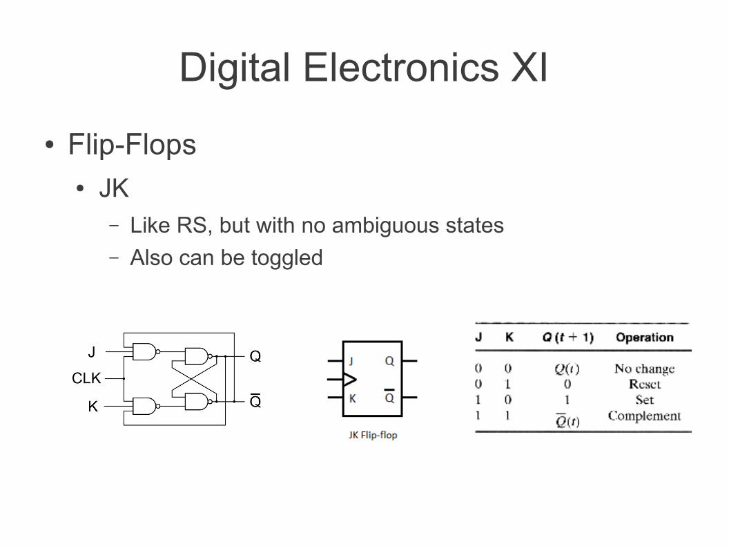
Digital Electronics XI
● Flip-Flops● JK
– Like RS, but with no ambiguous states– Also can be toggled
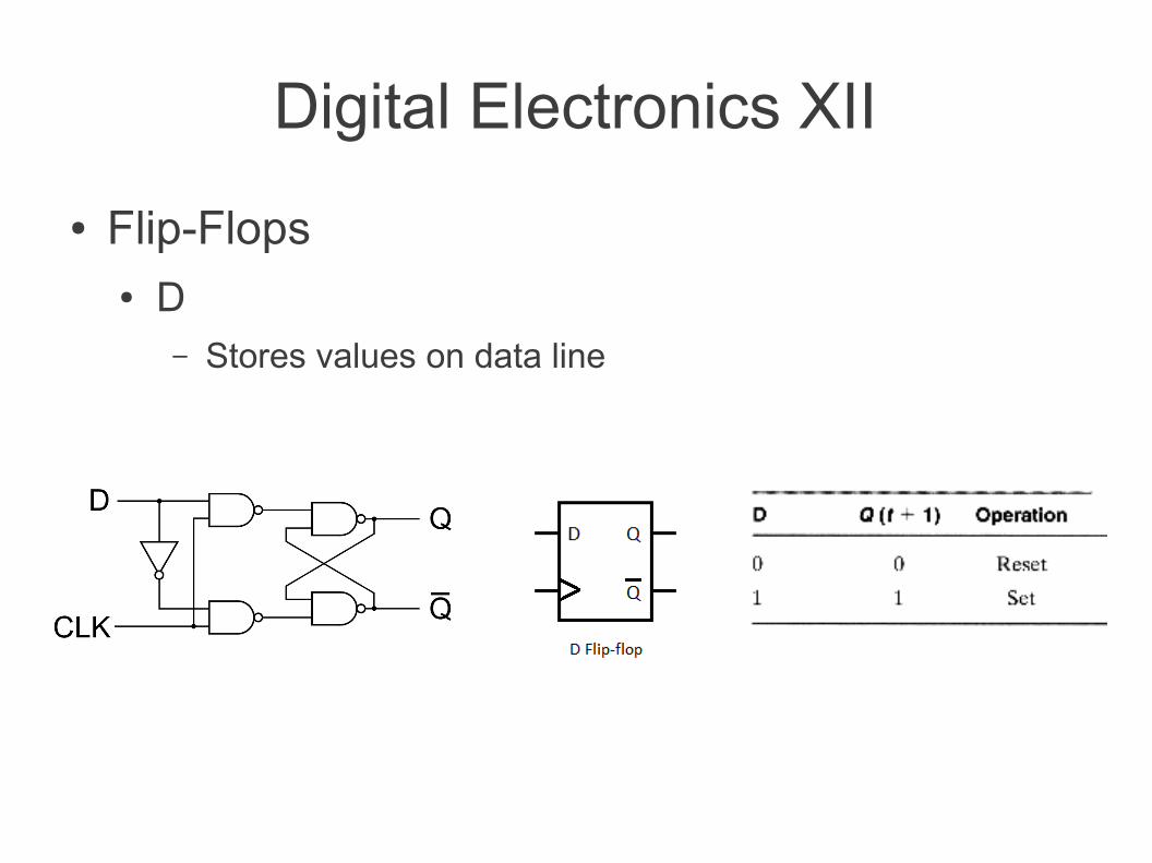
Digital Electronics XII
● Flip-Flops● D
– Stores values on data line
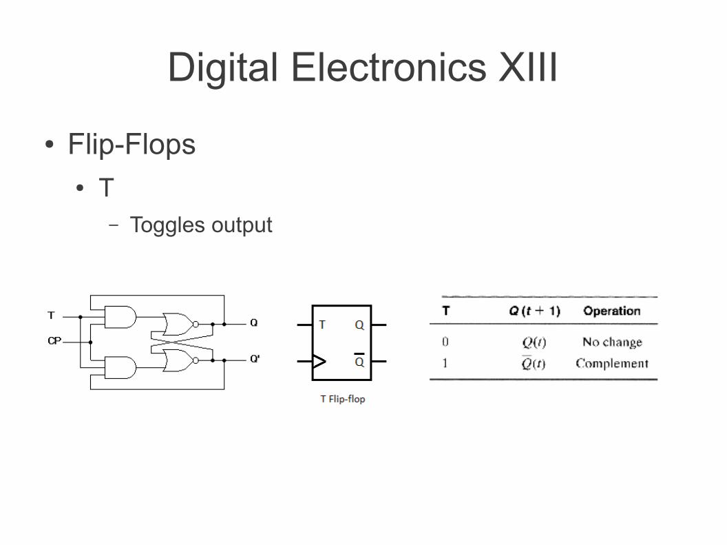
Digital Electronics XIII
● Flip-Flops● T
– Toggles output
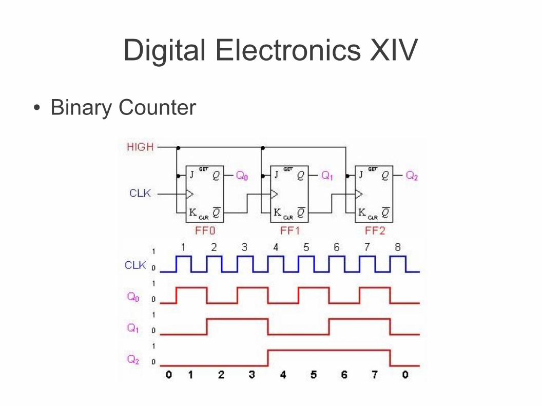
Digital Electronics XIV
● Binary Counter
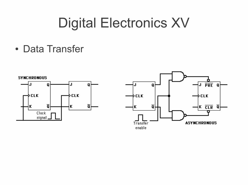
Digital Electronics XV
● Data Transfer
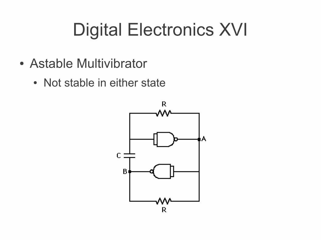
Digital Electronics XVI
● Astable Multivibrator● Not stable in either state
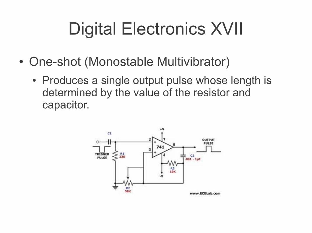
Digital Electronics XVII
● One-shot (Monostable Multivibrator)● Produces a single output pulse whose length is
determined by the value of the resistor and capacitor.
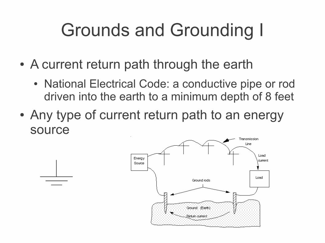
Grounds and Grounding I
● A current return path through the earth● National Electrical Code: a conductive pipe or rod
driven into the earth to a minimum depth of 8 feet
● Any type of current return path to an energy source
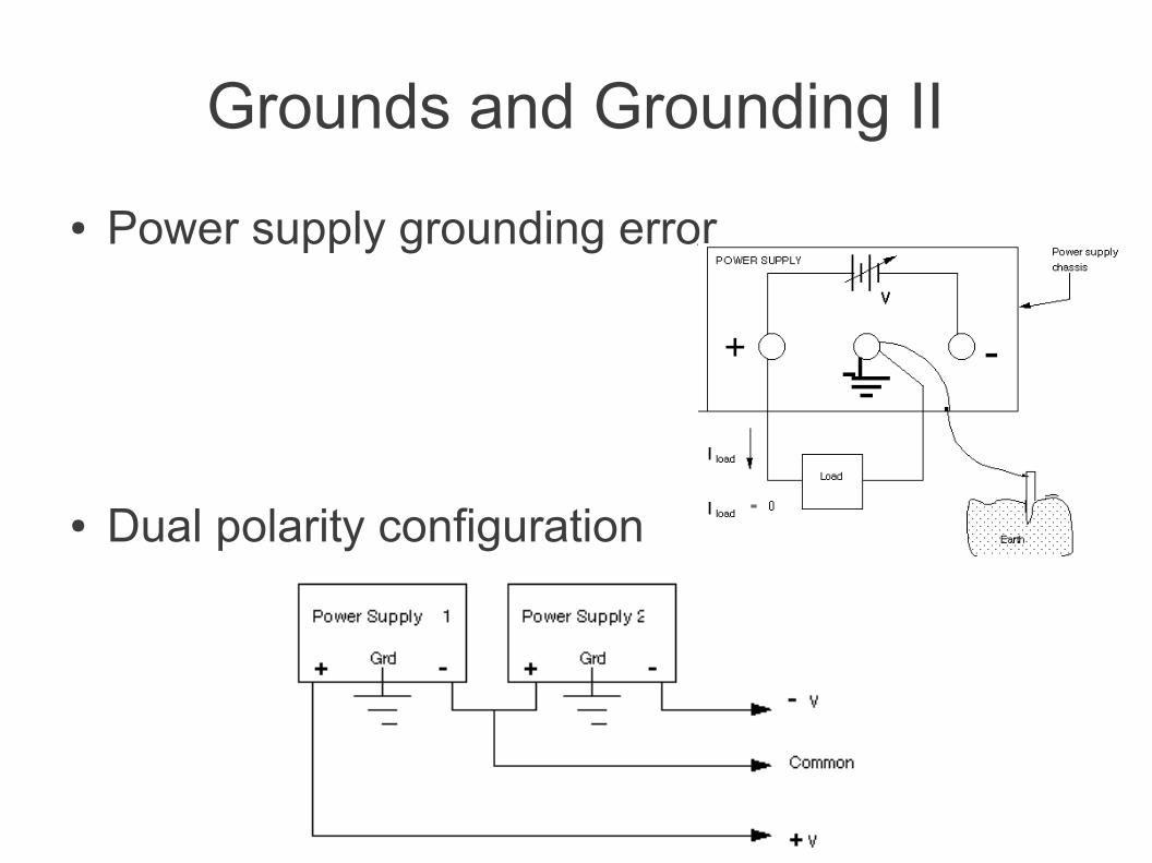
Grounds and Grounding II
● Power supply grounding error
● Dual polarity configuration
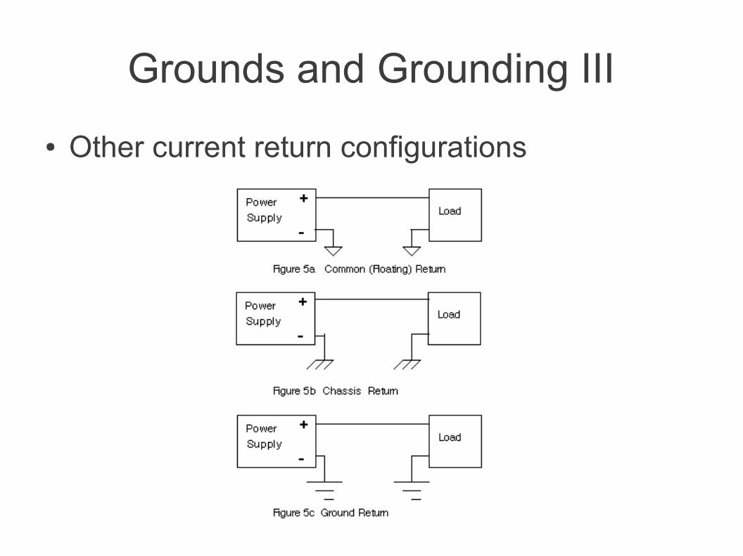
Grounds and Grounding III
● Other current return configurations
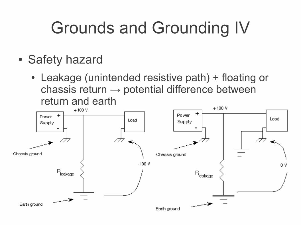
Grounds and Grounding IV
● Safety hazard● Leakage (unintended resistive path) + floating or
chassis return → potential difference between return and earth
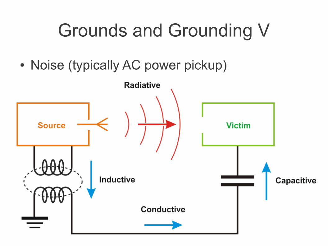
Grounds and Grounding V
● Noise (typically AC power pickup)
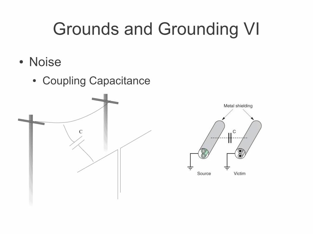
Grounds and Grounding VI
● Noise● Coupling Capacitance
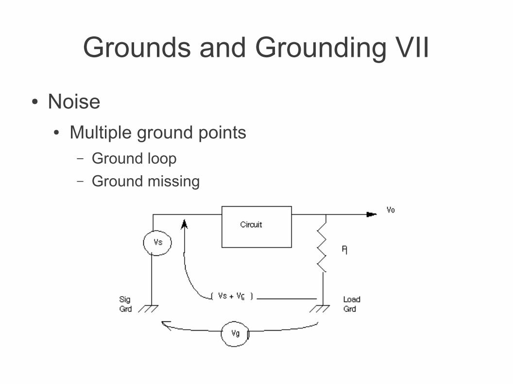
Grounds and Grounding VII
● Noise● Multiple ground points
– Ground loop– Ground missing
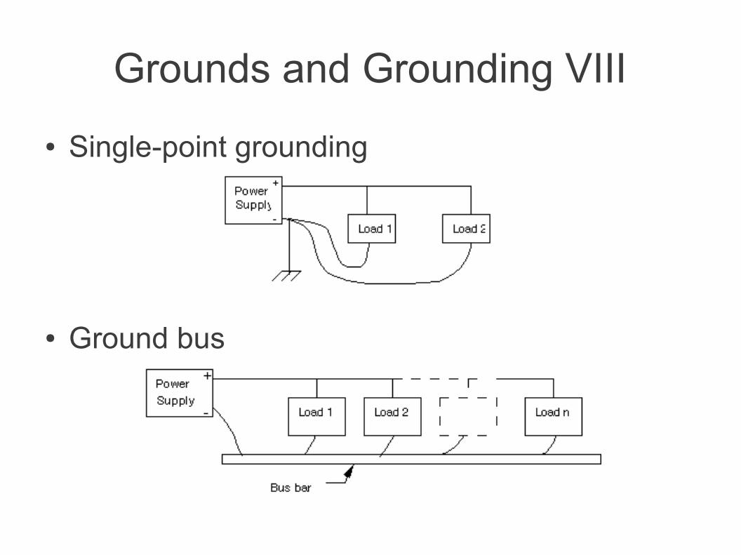
Grounds and Grounding VIII
● Single-point grounding
● Ground bus
Grounds and Grounding IX
● Analog and digital circuits should be grounded separately, then connected at a single point
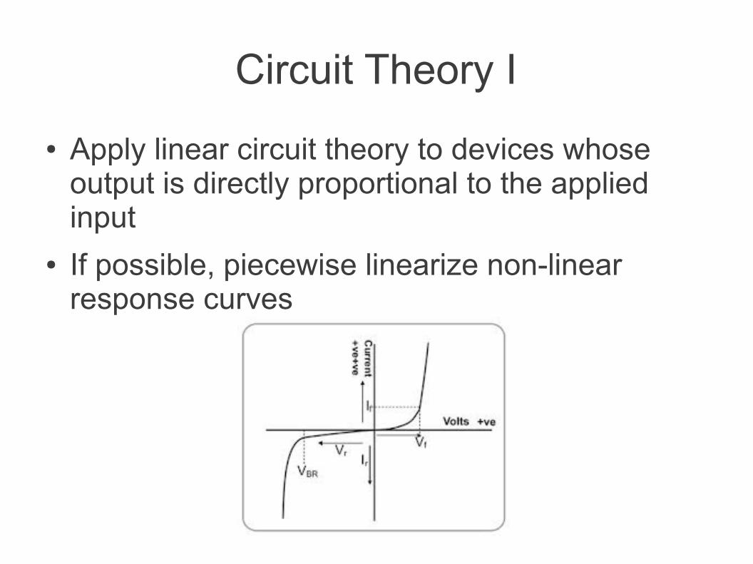
Circuit Theory I
● Apply linear circuit theory to devices whose output is directly proportional to the applied input
● If possible, piecewise linearize non-linear response curves

Electronic Properties of Solids
● Behavior of electrons (and holes): Fermi statistics
● Periodic lattice of crystalline solids: “free” electrons contained in energy bands
● Scattering and absorption/emission of phonons (vibrational quanta)
Fermi-Dirac Distribution
● Number of cells in a differential volume of phase space
●
● Number of states per unit volume per differential element
●
●