Axial Aluminum Electrolytic Capacitors PEG225 Series ... · Deviations in capacitance and tan δ...
9
1 © KEMET Electronics Corporation • P.O. Box 5928 • Greenville, SC 29606 (864) 963-6300 • www.kemet.com A4015_PEG225 • 6/8/2016 One world. One KEMET Benefits • 2,000 hours at +150°C • High CV • Extremely high ripple current • Up to 28 A ripple, RMS, continuous load • High vibration resistance • Polarized all-welded design • Outstanding electrical performance Overview KEMET's PEG225 is an electrolytic capacitor with outstanding electrical performance. The device has a polarized all-welded design, tinned copper wire leads, and a negative pole connected to the case. The PEG225 winding is housed in a cylindrical aluminum can with a high purity aluminum lid and high quality rubber gasket. Low ESR is the result of a low resistive electrolyte/paper system and an all-welded design. Thanks to its mechanical robustness, the PEG225 is suitable for use in mobile and aircraft installations with operation up to +150°C. Applications KEMET's PEG225 is a new generation of high performance axial electrolytic capacitors. It is designed for automotive applications with extremely high demands. Axial Aluminum Electrolytic Capacitors PEG225 Series, +125ºC and +150ºC Part Number System PEG225 H F 422 0 M E1 Series Rated Voltage (VDC) Size Code Capacitance Code (µF) Version Capacitance Tolerance Packaging Axial Aluminum Electrolytic H = 25 K = 40 M = 63 See Dimension Table The last two digits represent significant figures. The first digit indicates the total number digits. 0 = Standard Q = -10 +30% M = ±20% E1 = Bulk
Transcript of Axial Aluminum Electrolytic Capacitors PEG225 Series ... · Deviations in capacitance and tan δ...
1© KEMET Electronics Corporation • P.O. Box 5928 • Greenville, SC 29606 (864) 963-6300 • www.kemet.com A4015_PEG225 • 6/8/2016One world. One KEMET
Benefits
• 2,000 hours at +150°C • High CV• Extremely high ripple current• Up to 28 A ripple, RMS, continuous load • High vibration resistance• Polarized all-welded design• Outstanding electrical performance
Overview
KEMET's PEG225 is an electrolytic capacitor with outstanding electrical performance. The device has a polarized all-welded design, tinned copper wire leads, and a negative pole connected to the case. The PEG225 winding is housed in a cylindrical aluminum can with a high purity aluminum lid and high quality rubber gasket. Low ESR is the result of a low resistive electrolyte/paper system and an all-welded design. Thanks to its mechanical robustness, the PEG225 is suitable for use in mobile and aircraft installations with operation up to +150°C.
Applications
KEMET's PEG225 is a new generation of high performance axial electrolytic capacitors. It is designed for automotive applications with extremely high demands.
Axial Aluminum Electrolytic Capacitors
PEG225 Series, +125ºC and +150ºC
Part Number System
PEG225 H F 422 0 M E1
Series Rated Voltage (VDC) Size Code Capacitance Code (µF) Version Capacitance
Tolerance Packaging
Axial Aluminum Electrolytic
H = 25 K = 40 M = 63
See Dimension Table
The last two digits represent significant
figures. The first digit indicates the
total number digits.
0 = Standard Q = -10 +30% M = ±20%
E1 = Bulk
2© KEMET Electronics Corporation • P.O. Box 5928 • Greenville, SC 29606 (864) 963-6300 • www.kemet.com A4015_PEG225 • 6/8/2016
Axial Aluminum Electrolytic Capacitors – PEG225 Series, +125ºC and +150ºC
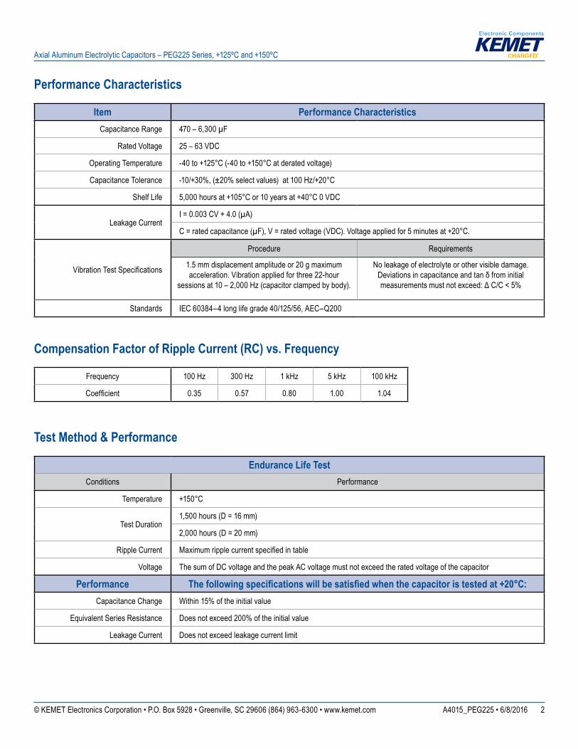
Performance Characteristics
Item Performance CharacteristicsCapacitance Range 470 – 6,300 µF
Rated Voltage 25 – 63 VDC
Operating Temperature -40 to +125°C (-40 to +150°C at derated voltage)
Capacitance Tolerance -10/+30%, (±20% select values) at 100 Hz/+20°C
Shelf Life 5,000 hours at +105°C or 10 years at +40°C 0 VDC
Leakage CurrentI = 0.003 CV + 4.0 (µA)
C = rated capacitance (µF), V = rated voltage (VDC). Voltage applied for 5 minutes at +20°C.
Vibration Test Specifications
Procedure Requirements
1.5 mm displacement amplitude or 20 g maximum acceleration. Vibration applied for three 22-hour
sessions at 10 – 2,000 Hz (capacitor clamped by body).
No leakage of electrolyte or other visible damage. Deviations in capacitance and tan δ from initial measurements must not exceed: Δ C/C < 5%
Standards IEC 60384–4 long life grade 40/125/56, AEC–Q200
Compensation Factor of Ripple Current (RC) vs. Frequency
Frequency 100 Hz 300 Hz 1 kHz 5 kHz 100 kHz
Coefficient 0.35 0.57 0.80 1.00 1.04
Test Method & Performance
Endurance Life TestConditions Performance
Temperature +150°C
Test Duration1,500 hours (D = 16 mm)
2,000 hours (D = 20 mm)
Ripple Current Maximum ripple current specified in table
Voltage The sum of DC voltage and the peak AC voltage must not exceed the rated voltage of the capacitor
Performance The following specifications will be satisfied when the capacitor is tested at +20°C:Capacitance Change Within 15% of the initial value
Equivalent Series Resistance Does not exceed 200% of the initial value
Leakage Current Does not exceed leakage current limit
3© KEMET Electronics Corporation • P.O. Box 5928 • Greenville, SC 29606 (864) 963-6300 • www.kemet.com A4015_PEG225 • 6/8/2016
Axial Aluminum Electrolytic Capacitors – PEG225 Series, +125ºC and +150ºC
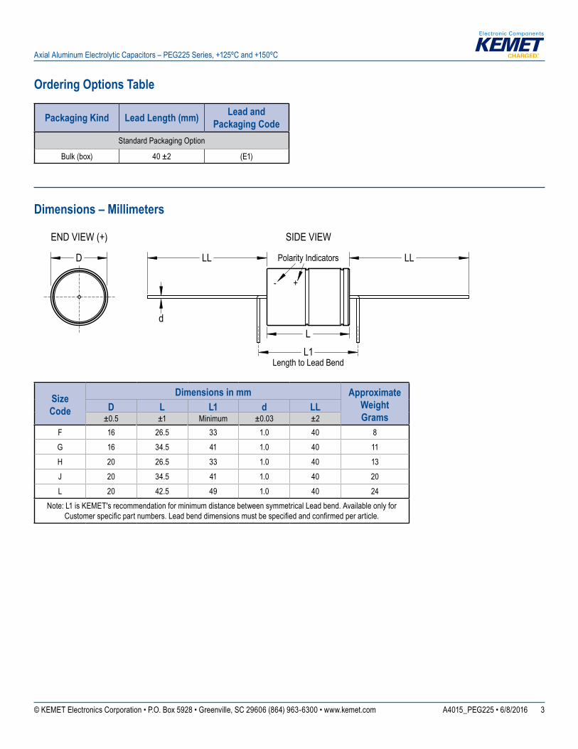
Ordering Options Table
Packaging Kind Lead Length (mm) Lead and Packaging Code
Standard Packaging Option
Bulk (box) 40 ±2 (E1)
Dimensions – Millimeters
SIDE VIEWEND VIEW (+)
L L1
d
Length to Lead Bend
LL LL D Polarity Indicators
- +
SizeCode
Dimensions in mm Approximate Weight Grams
D L L1 d LL±0.5 ±1 Minimum ±0.03 ±2
F 16 26.5 33 1.0 40 8G 16 34.5 41 1.0 40 11H 20 26.5 33 1.0 40 13J 20 34.5 41 1.0 40 20L 20 42.5 49 1.0 40 24
Note: L1 is KEMET's recommendation for minimum distance between symmetrical Lead bend. Available only for Customer specific part numbers. Lead bend dimensions must be specified and confirmed per article.
4© KEMET Electronics Corporation • P.O. Box 5928 • Greenville, SC 29606 (864) 963-6300 • www.kemet.com A4015_PEG225 • 6/8/2016
Axial Aluminum Electrolytic Capacitors – PEG225 Series, +125ºC and +150ºC
Shelf Life
The capacitance, ESR and impedance of a capacitor will not change significantly after extended storage periods, however the leakage current will very slowly increase. KEMET products are particularly stable and allow a shelf life in excess of ten years at 40°C. See sectional specification under each product series for specific data.
Failure Rate
Estimated field failure rate: ≤ 0.15 ppm (failures per year/produced number of capacitors per year). The expected failure rate for this capacitor range is based on field experience for capacitors with structural similarity.
Environmental Compliance
As an environmentally conscious company, KEMET is working continuously with improvements concerning the environmental effects of both our capacitors and their production. In Europe (RoHS Directive) and in some other geographical areas like China, legislation has been put in place to prevent the use of some hazardous materials, such as lead (Pb), in electronic equipment. All products in this catalog are produced to help our customers’ obligations to guarantee their products and fulfill these legislative requirements. The only material of concern in our products has been lead (Pb), which has been removed from all designs to fulfill the requirement of containing less than 0.1% of lead in any homogeneous material. KEMET will closely follow any changes in legislation world wide and makes any necessary changes in its products, whenever needed.
Some customer segments such as medical, military and automotive electronics may still require the use of lead in electrode coatings. To clarify the situation and distinguish products from each other, a special symbol is used on the packaging labels for RoHS compatible capacitors.
Because of customer requirements, there may appear additional markings such as LF = Lead Free or LFW = Lead Free Wires on the label.
5© KEMET Electronics Corporation • P.O. Box 5928 • Greenville, SC 29606 (864) 963-6300 • www.kemet.com A4015_PEG225 • 6/8/2016
Axial Aluminum Electrolytic Capacitors – PEG225 Series, +125ºC and +150ºC
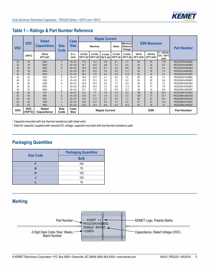
Table 1 – Ratings & Part Number Reference
1 Capacitor-mounted with low thermal resistance path (heat-sink).2 Valid for capacitor supplied with reduced DC voltage, capacitor-mounted with low thermal resistance path.
Packaging Quantities
Size CodePackaging Quantities
BulkF 100G 75H 125J 100L 75
Marking
Capacitance, Rated Voltage (VDC)
Part Number KEMET Logo, Polarity Marks
4 Digit Date Code (Year, Week), Batch Number
VDCVDC Rated
Capacitance Size Code
Case Size
Ripple CurrentESR Maximum
Part NumberMaximum RatedMaximum(Reduced Voltage)
(150ºC) 100 Hz 20°C (µF)
D x L(mm)
≥ 5 kHz 125°C (A)1
≥ 5 kHz 140°C (A)2
≥ 5 kHz 150°C (A)2
≥ 5 kHz 125°C (A)
≥ 5 kHz 125°C (A)
100 Hz20°C (mΩ)
100 kHz 20°C (mΩ)
5 – 100 kHz 125 – 150°C
(mΩ)25 18 2200 F 16 x 27 17.3 11.0 4.9 6.1 7.7 60 34 11.9 PEG225HF4220ME125 18 3000 G 16 x 35 19.7 12.5 5.6 7.4 9.4 44 25 9.2 PEG225HG4300ME125 18 3600 H 20 x 27 23.5 14.9 6.7 7.6 9.6 38 22 9.4 PEG225HH4360QE125 18 4800 J 20 x 35 26.7 16.9 7.6 9.2 11.7 28 16 7.3 PEG225HJ4480QE125 18 6300 L 20 x 43 28.3 17.9 8.0 10.2 12.9 24 14 6.5 PEG225HL4630QE140 32 1200 F 16 x 27 16.6 10.5 4.7 5.8 7.4 80 36 13 PEG225KF4120ME140 32 1800 G 16 x 35 19.3 12.2 5.5 7.2 9.2 55 25 9.6 PEG225KG4180ME140 32 2000 H 20 x 27 22.8 14.4 6.5 7.3 9.3 50 23 10 PEG225KH4200QE140 32 3000 J 20 x 35 25.8 16.3 7.3 8.9 11.3 35 17 7.8 PEG225KJ4300QE140 32 3900 L 20 x 43 27.7 17.5 7.8 10.0 12.7 28 14 6.8 PEG225KL4390QE163 54 470 F 16 x 27 12.1 7.7 3.4 4.2 5.3 156 52 24.3 PEG225MF3470QE163 54 680 G 16 x 35 13.8 8.7 3.9 5.3 6.7 109 37 18.7 PEG225MG3680QE163 54 900 H 20 x 27 18.0 11.4 5.1 5.8 7.3 86 31 16.1 PEG225MH3900QE163 54 1400 J 20 x 35 20.9 13.2 5.9 7.3 9.2 57 22 11.9 PEG225MJ4140QE163 54 1800 L 20 x 43 22.8 14.4 6.5 8.3 10.5 45 18 10 PEG225ML4180QE1
VDC VDC (150ºC)
Rated Capacitance
Size Code
Case Size Ripple Current ESR Part Number
6© KEMET Electronics Corporation • P.O. Box 5928 • Greenville, SC 29606 (864) 963-6300 • www.kemet.com A4015_PEG225 • 6/8/2016
Axial Aluminum Electrolytic Capacitors – PEG225 Series, +125ºC and +150ºC
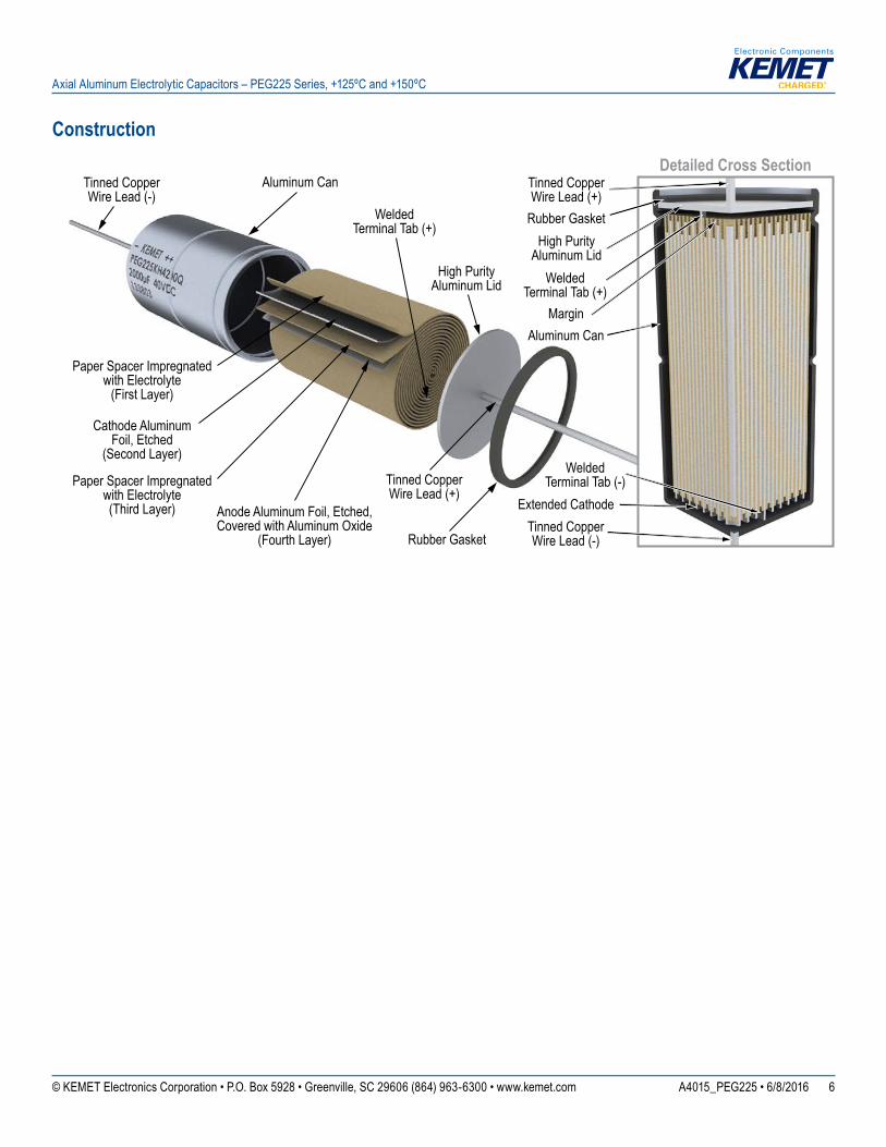
ConstructionDetailed Cross Section
Margin
Rubber Gasket
Aluminum Can
Welded Terminal Tab (+)
Tinned Copper Wire Lead (+)
Aluminum Can
Tinned CopperWire Lead (-)
Paper Spacer Impregnatedwith Electrolyte
(First Layer)
Paper Spacer Impregnated with Electrolyte (Third Layer) Anode Aluminum Foil, Etched,
Covered with Aluminum Oxide (Fourth Layer)
Cathode Aluminum Foil, Etched
(Second Layer)
High Purity Aluminum Lid
Rubber GasketHigh Purity
Aluminum LidWelded
Terminal Tab (+)
Tinned CopperWire Lead (+)
Welded Terminal Tab (-)
Tinned CopperWire Lead (-)
Extended Cathode
7© KEMET Electronics Corporation • P.O. Box 5928 • Greenville, SC 29606 (864) 963-6300 • www.kemet.com A4015_PEG225 • 6/8/2016
Axial Aluminum Electrolytic Capacitors – PEG225 Series, +125ºC and +150ºC
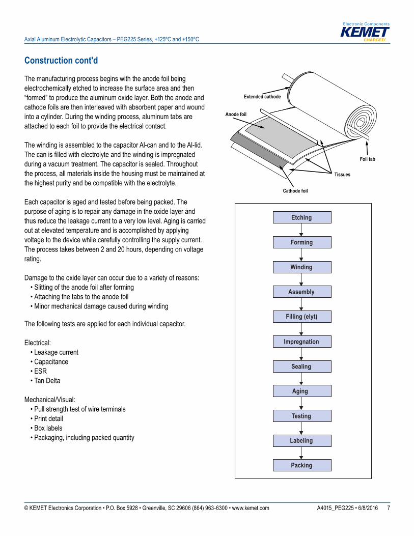
Anode foil
Cathode foil
Tissues
Foil tab
Extended cathode
Aging
Etching
Forming
Winding
Assembly
Filling (elyt)
Impregnation
Testing
Labeling
Packing
Sealing
Construction cont'd
The manufacturing process begins with the anode foil being electrochemically etched to increase the surface area and then “formed” to produce the aluminum oxide layer. Both the anode and cathode foils are then interleaved with absorbent paper and wound into a cylinder. During the winding process, aluminum tabs are attached to each foil to provide the electrical contact. The winding is assembled to the capacitor Al-can and to the Al-lid. The can is filled with electrolyte and the winding is impregnated during a vacuum treatment. The capacitor is sealed. Throughout the process, all materials inside the housing must be maintained at the highest purity and be compatible with the electrolyte. Each capacitor is aged and tested before being packed. The purpose of aging is to repair any damage in the oxide layer and thus reduce the leakage current to a very low level. Aging is carried out at elevated temperature and is accomplished by applying voltage to the device while carefully controlling the supply current. The process takes between 2 and 20 hours, depending on voltage rating.
Damage to the oxide layer can occur due to a variety of reasons: • Slitting of the anode foil after forming • Attaching the tabs to the anode foil • Minor mechanical damage caused during winding
The following tests are applied for each individual capacitor.
Electrical: • Leakage current • Capacitance • ESR • Tan Delta
Mechanical/Visual: • Pull strength test of wire terminals • Print detail • Box labels • Packaging, including packed quantity
8© KEMET Electronics Corporation • P.O. Box 5928 • Greenville, SC 29606 (864) 963-6300 • www.kemet.com A4015_PEG225 • 6/8/2016
Axial Aluminum Electrolytic Capacitors – PEG225 Series, +125ºC and +150ºC
KEMET Corporation World Headquarters
2835 KEMET WaySimpsonville, SC 29681
Mailing Address:P.O. Box 5928 Greenville, SC 29606
www.kemet.com Tel: 864-963-6300 Fax: 864-963-6521
Corporate Offi cesFort Lauderdale, FLTel: 954-766-2800
North America
NortheastWilmington, MATel: 978-658-1663
SoutheastLake Mary, FLTel: 407-855-8886
CentralNovi, MITel: 248-994-1030
Irving, TXTel: 972-915-6041
WestMilpitas, CATel: 408-433-9950
Mexico Guadalajara, Jalisco Tel: 52-33-3123-2141
Europe
Southern EuropeSasso Marconi, ItalyTel: 39-051-939111
Skopje, MacedoniaTel: 389-2-55-14-623
Central EuropeLandsberg, Germany Tel: 49-8191-3350800
Kamen, GermanyTel: 49-2307-438110
Northern EuropeWyboston, United Kingdom Tel: 44-1480-273082
Espoo, FinlandTel: 358-9-5406-5000
Asia
Northeast AsiaHong KongTel: 852-2305-1168
Shenzhen, ChinaTel: 86-755-2518-1306
Beijing, ChinaTel: 86-10-5877-1075
Shanghai, ChinaTel: 86-21-6447-0707
Seoul, South KoreaTel: 82-2-6294-0550
Taipei, TaiwanTel: 886-2-27528585
Southeast AsiaSingaporeTel: 65-6701-8033
Penang, MalaysiaTel: 60-4-6430200
Bangalore, IndiaTel: 91-806-53-76817
Note: KEMET reserves the right to modify minor details of internal and external construction at any time in the interest of product improvement. KEMET does not assume any responsibility for infringement that might result from the use of KEMET Capacitors in potential circuit designs. KEMET is a registered trademark of KEMET Electronics Corporation.
9© KEMET Electronics Corporation • P.O. Box 5928 • Greenville, SC 29606 (864) 963-6300 • www.kemet.com A4015_PEG225 • 6/8/2016
Axial Aluminum Electrolytic Capacitors – PEG225 Series, +125ºC and +150ºC
DisclaimerAll product specifi cations, statements, information and data (collectively, the “Information”) in this datasheet are subject to change. The customer is responsible for checking and verifying the extent to which the Information contained in this publication is applicable to an order at the time the order is placed.
All Information given herein is believed to be accurate and reliable, but it is presented without guarantee, warranty, or responsibility of any kind, expressed or implied.
Statements of suitability for certain applications are based on KEMET Electronics Corporation’s (“KEMET”) knowledge of typical operating conditions for such applications, but are not intended to constitute – and KEMET specifi cally disclaims – any warranty concerning suitability for a specifi c customer application or use. The Information is intended for use only by customers who have the requisite experience and capability to determine the correct products for their application. Any technical advice inferred from this Information or otherwise provided by KEMET with reference to the use of KEMET’s products is given gratis, and KEMET assumes no obligation or liability for the advice given or results obtained.
Although KEMET designs and manufactures its products to the most stringent quality and safety standards, given the current state of the art, isolated component failures may still occur. Accordingly, customer applications which require a high degree of reliability or safety should employ suitable designs or other safeguards (such as installation of protective circuitry or redundancies) in order to ensure that the failure of an electrical component does not result in a risk of personal injury or property damage.
Although all product–related warnings, cautions and notes must be observed, the customer should not assume that all safety measures are indicted or that other measures may not be required.