AUTOTEST BENNING CM 5–1
15
Auto Auto Sense ZeroLoZi � HOLD AUTOTEST AUTO BACKLIT 600A 600V CAT.IV DCA ZERO PRESS 1 SEC POWER OFF PRESS 3 SEC TRUE RMS CAT.IV 600V CAT.III 1000V D Bedienungsanleitung Operating manual F Notice d‘emploi E Instrucciones de servicio Návod k obsluze Οδηγίες χρήσεως H Kezelési utasítás I Istruzioni d’uso Gebruiksaanwijzing Instrukcja obsługi Instructiuni de folosire Инструкция по эксплуатации индикатора напряжения S Bruksanvisning Kullanma Talimati BENNING CM 5–1
Transcript of AUTOTEST BENNING CM 5–1
Auto AutoSenseZeroLoZi
� HOLD
AUTOTEST
AUTO BACKLIT
600A600V
CAT.IV
DCA ZEROPRESS 1 SECPOWER OFFPRESS 3 SEC
TRUE RMS
CAT.IV600V
CAT.III1000V
D Bedienungsanleitung Operating manualF Notice d‘emploiE Instrucciones de servicio Návod k obsluze Οδηγίες χρήσεωςH Kezelési utasításI Istruzioni d’uso Gebruiksaanwijzing Instrukcja obsługi Instructiuni de folosire Инструкция по эксплуатации
индикатора напряженияS Bruksanvisning Kullanma Talimati
BEN
NIN
G C
M 5
–1
Auto AutoSenseZeroLoZi
· HOLD
AUTOTEST
AUTO BACKLIT
600A600V
CAT.IV
DCA ZEROPRESS 1 SECPOWER OFFPRESS 3 SEC
TRUE RMS
CAT.IV600V
CAT.III1000V
BENNING CM 5-109/ 2009
D F E H I S
Bild 1: GerätefrontseiteFig. 1: Front tester panelFig. 1: Panneau avant de l‘appareilFig. 1: Parte frontal del equipoObr. 1: Přední strana přístrojeΣικόνα 1: Μπροστινή όψη1. ábra: A mérõkészülék elölnézete
Ill. 1: Lato anteriore apparecchioFig. 1: Voorzijde van het apparaatRys. 1: Panel przedni przyrząduImaginea 1: Partea frontală a aparatuluiРис. 1: Вид спередиFig. 1: FramsidaResim 1: Cihaz önyüzü

BENNING CM 5-109/ 2009
D F E H I S
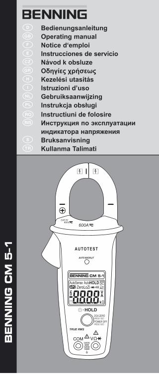
Bild 2: Gleich-/ Wechselspannungsmessung mit AUTOTEST-Funktion
Fig. 2: Direct/ alternating voltage measurement with AUTOTEST function
Fig. 2: Mesure de tension continue/ alternative avec fonction AUTOTEST
Fig. 2: Medición de tensión contínua/ alterna con función AUTOTEST
Obr. 2: Měření stejnosměrného/ střídavého napětí s funkcí AUTOTEST
Σικόνα 2: Μέτρηση συνεχούς/ εναλλασσόμενης τάσης και λειτουργία AUTOTEST
2. ábra: Egyen- es váltakozó feszültség mérés AUTOTEST művelettel
Ill. 2: Misura tensione continua/ alternata con funzione AUTOTEST
Fig. 2: Meten van gelijkspanning/ wisselspanning met AUTOTEST-functie
Rys.2: Pomiar napięcia stałego/ przemiennego z funkcją AUTOTEST
Imaginea 2: Măsurarea tensiunii continue/ alternative cu funcţia AUTOTEST
Рис. 2: Измерение напряжения постоянного/ переменного тока при помощи функции AUTOTEST
Fig. 2: Likspänningsmätning/ växelspänningsmätning med AUTOTEST-funktion
Resim 2: AUTOTEST işleviyle doğru/ alternatif gerilim ölçümü
Bild 3: Gleich-/ Wechselstrommessung mit AUTOTEST-Funktion
Fig. 3: Direct/ alternating current measurement with AUTOTEST function
Fig. 3: Mesure de courant continue/ alternative avec fonction AUTOTEST
Fig. 3: Medición de corriente contínua/ alterna con función AUTOTEST
Obr. 3: Měření stejnosměrného/ střídavého proudu s funkcí AUTOTEST
Σικόνα 3: Μέτρηση συνεχούς/ εναλλασσόμενης έντασης ρεύματος και λειτουργία AUTOTEST
3. ábra: Egyen- es váltakozó áram mérés AUTOTEST művelettel
Ill. 3: Misura corrente continua/ alternata con funzione AUTOTEST
Fig. 3: Meten van gelijkstroom/ wisselstroom met AUTOTEST-functie
Rys.3: Pomiar prądu stałego/ przemiennego z funkcją AUTOTEST
Imaginea 3: Măsurarea curentului continuu/ alternativ cu funcţia AUTOTEST
Рис. 3: Измерение величины постоянного/ переменного тока при помощи функции AUTOTEST
Fig. 3: Likströmsmätning/ växelströmsmätning med AUTOTEST-funktion
Resim 3: AUTOTEST işleviyle doğru/ alternatif akım ölçümü
Auto AutoSenseZeroLoZi
· HOLD
AUTOTEST
AUTO BACKLIT
600A600V
CAT.IV
DCA ZEROPRESS 1 SECPOWER OFFPRESS 3 SEC
TRUE RMS
CAT.IV600V
CAT.III1000V
Auto AutoSenseZeroLoZi
· HOLD
AUTOTEST
AUTO BACKLIT
600A600V
CAT.IV
DCA ZEROPRESS 1 SECPOWER OFFPRESS 3 SEC
TRUE RMS
CAT.IV600V
CAT.III1000V
BENNING CM 5-109/ 2009
D F E H I S
Auto AutoSenseZeroLoZi
· HOLD
AUTOTEST
AUTO BACKLIT
600A600V
CAT.IV
DCA ZEROPRESS 1 SECPOWER OFFPRESS 3 SEC
TRUE RMS
CAT.IV600V
CAT.III1000V
Auto AutoSenseZeroLoZi
· HOLD
AUTOTEST
AUTO BACKLIT
600A600V
CAT.IV
DCA ZEROPRESS 1 SECPOWER OFFPRESS 3 SEC
TRUE RMS
CAT.IV600V
CAT.III1000V
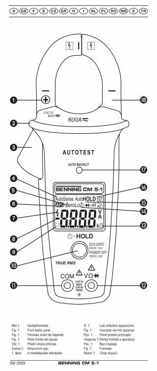
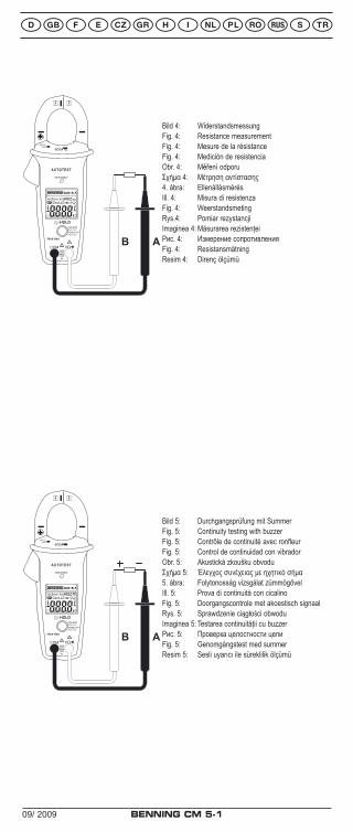
Bild 5: Durchgangsprüfung mit SummerFig. 5: Continuity testing with buzzerFig. 5: Contrôle de continuité avec ronfleurFig. 5: Control de continuidad con vibradorObr. 5: Akustická zkoušku obvoduΣχήμα 5: Έλεγχος συνέχειας με ηχητικό σήμα5. ábra: Folytonosság vizsgálat zümmögővelIll. 5: Prova di continuità con cicalinoFig. 5: Doorgangscontrole met akoestisch signaalRys. 5: Sprawdzenie ciągłości obwoduImaginea 5: Testarea continuităţii cu buzzerРис. 5: Проверка целостности цепиFig. 5: Genomgångstest med summerResim 5: Sesli uyarıcı ile süreklilik ölçümü
Bild 4: WiderstandsmessungFig. 4: Resistance measurementFig. 4: Mesure de la résistanceFig. 4: Medición de resistenciaObr. 4: Měření odporuΣχήμα 4: Μέτρηση αντίστασης4. ábra: EllenállásmérésIll. 4: Misura di resistenzaFig. 4: WeerstandsmetingRys.4: Pomiar rezystancjiImaginea 4: Măsurarea rezistenţeiРис. 4: Измерение сопротивленияFig. 4: ResistansmätningResim 4: Direnç ölçümü
BENNING CM 5-109/ 2009
D F E H I S
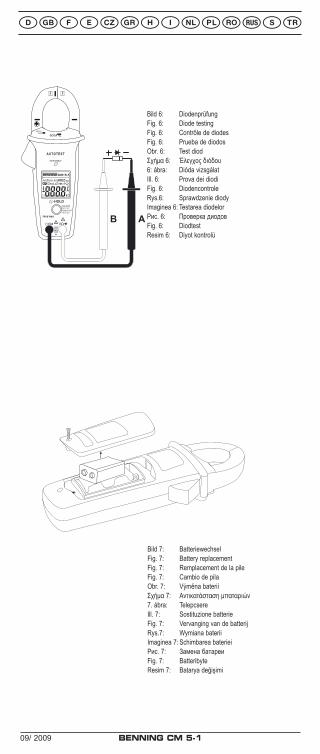
Bild 7: BatteriewechselFig. 7: Battery replacementFig. 7: Remplacement de la pileFig. 7: Cambio de pilaObr. 7: Výměna bateriíΣχήμα 7: Αντικατάσταση μπαταριών7. ábra: TelepcsereIll. 7: Sostituzione batterieFig. 7: Vervanging van de batterijRys.7: Wymiana bateriiImaginea 7: Schimbarea baterieiРис. 7: Замена батареиFig. 7: BatteribyteResim 7: Batarya değişimi
Bild 6: DiodenprüfungFig. 6: Diode testingFig. 6: Contrôle de diodesFig. 6: Prueba de diodosObr. 6: Test diodΣχήμα 6: Έλεγχος διόδου6: ábra: Dióda vizsgálatIll. 6: Prova dei diodiFig. 6: DiodencontroleRys.6: Sprawdzenie diodyImaginea 6: Testarea diodelorРис. 6: Проверка диодовFig. 6: DiodtestResim 6: Diyot kontrolü
Auto AutoSenseZeroLoZi
· HOLD
AUTOTEST
AUTO BACKLIT
600A600V
CAT.IV
DCA ZEROPRESS 1 SECPOWER OFFPRESS 3 SEC
TRUE RMS
CAT.IV600V
CAT.III1000V
BENNING CM 5-109/ 2009 10
Operating instructionsBENNING CM 5-1
Digital current clamp multimeter with AUTOTEST function for - Direct voltage measurements - Alternating voltage measurements - Direct current measurements - Alternating current measurements - Resistance measurements - Continuity testing - Diode testing
Table of contents1. User notes2. Safety note3. Scope of delivery4. Unit description5. General information6. Ambient conditions7. Electrical specifications8. Measuring with the BENNING CM 5-19. Maintenance10. Technical data of the measuring accessories11. Environmental note
1. User notesThese operating instructions are intended for
- qualified electricians and - electrotechnically trained persons.
The BENNING CM 5-1 is intended for making measurements in dry environment. It must not be used in power circuits with a nominal voltage higher than 1000 V DC and 750 V AC (More details in Section 6. “Ambient conditions”).
The following symbols are used in these operating instructions and on the BENNING CM 5-1:
Application around and removal from HAZARDOUS LIVE conductors is permitted.
Warning of electrical danger!Indicates instructions which must be followed to avoid danger to persons.
Important, comply with the documentation!The symbol indicates that the information provided in the operating instructions must be followed with in order to avoid risks.
This symbol on the BENNING CM 5-1 means that the BENNING CM 5-1 is totally insulated (protection class II).
This symbol on the BENNING CM 5-1 means that the BENNING CM 5-1 complies with the EU directives.
This symbol appears on the display to indicate a discharged battery.
This symbol designates the „continuity test“ range. The buzzer is used for the acoustic result output.
(DC) Direct voltage or current.
(AC) Alternating voltage or current.
Ground (Voltage against ground).
NoteAfter unmark the adhesive label „Warnung...“ (on battery compartment lid) the English text appears.
BENNING CM 5-109/ 2009 11
2. Safety noteThe instrument is built and tested in accordance withDIN VDE 0411 part 1/ EN 61010-1and has left the factory in perfectly safe technical condition.To maintain this condition and to ensure safe operation of the multimeter, the user must observe the notes and warnings given in these instructions at all times. Improper handling and non-observance of the warnings might involve severe injuries or danger to life.
WARNING! Be extremely careful when working with bare conductors or main line carrier! Contact with live conductors will cause an electric shock!
The BENNING CM 5-1 may be used only in electrical circuits of over voltage category III with a maximum voltage of 1000 V or of over voltage category IV with a maximum voltage of 600 V between the conductor and ground. Remember that work on electrical components of all kinds is dangerous. Even low-voltages of 30 V AC and 60 V DC may be dangerous to human life.
Before starting the multimeter, always check it as well as all measuring leads and wires for signs of damage.
Should it appear that safe operation of the multimeter is no longer possible, it should be shut down immediately and secured to prevent that it is switched on accidentally.
It may be assumed that safe operation is no longer possible:- if the instrument or the measuring leads show visible signs of damage, or- if the multimeter no longer works, or- after long periods of storage under unfavourable conditions, or- after being subject to rough transportation, or- if the device or the measuring leads are exposed to moisture, or- if the self-test fails and „FAIL“ is shown on the display.
In order to avoid danger,- do not touch the bare probe tips of the measuring leads
measuring leads,- insert the measurement leads in the appropriately
designated measuring sockets on the multimeter
Maintenance:Do not open the multimeter, because it contains no components which can be repaired by the user. Repair and service must be carried out by qualified personnel only!
Cleaning:Regularly wipe the housing by means of a dry cloth and cleaning agent. Do not use any polishing agents or solvents!
3. Scope of deliveryThe scope of delivery for the BENNING CM 5-1 comprises: 3.1 one BENNING CM 5-1, 3.2 one safety measuring leads, red (L = 1.4 m; probe tip diameter =
4 mm) 3.3 one safety measuring leads, black (L = 1.4 m; probe tip diameter =
4 mm) 3.4 one compact protective pouch, 3.5 a 9 V block battery 3.6 one operating manual
Parts subject to wear:- The BENNING CM 5-1 is fed by a 9 V block battery (IEC 6 LR 61)- The above-mentioned safety measuring leads ATL-2 (tested accessories)
correspond to CAT III 1000 V/ CAT IV 600 V and are approved for a current of 10 A (part no. 044118).
BENNING CM 5-109/ 2009 12
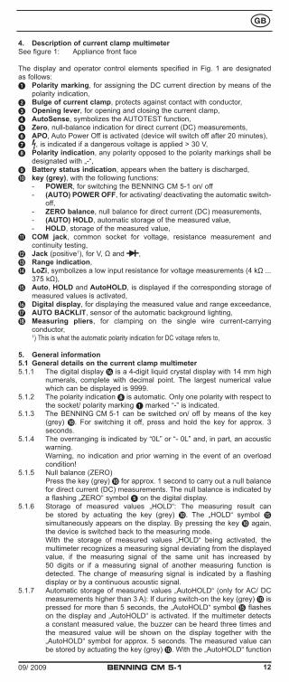
4. Description of current clamp multimeterSee figure 1: Appliance front face
The display and operator control elements specified in Fig. 1 are designated as follows:1 Polarity marking, for assigning the DC current direction by means of the
polarity indication,2 Bulge of current clamp, protects against contact with conductor,3 Opening lever, for opening and closing the current clamp,4 AutoSense, symbolizes the AUTOTEST function,5 Zero, null-balance indication for direct current (DC) measurements,6 APO, Auto Power Off is activated (device will switch off after 20 minutes),7 , is indicated if a dangerous voltage is applied > 30 V,8 Polarity indication, any polarity opposed to the polarity markings shall be
designated with „-“,9 Battery status indication, appears when the battery is discharged,J key (grey), with the following functions: - POWER, for switching the BENNING CM 5-1 on/ off - (AUTO) POWER OFF, for activating/ deactivating the automatic switch-
off, - ZERO balance, null balance for direct current (DC) measurements, - (AUTO) HOLD, automatic storage of the measured value, - HOLD, storage of the measured value,K COM jack, common socket for voltage, resistance measurement and
continuity testing,L Jack (positive1), for V, Ω and ,M Range indication,N LoZi, symbolizes a low input resistance for voltage measurements (4 kΩ ...
375 kΩ),O Auto, HOLD and AutoHOLD, is displayed if the corresponding storage of
measured values is activated, Digital display, for displaying the measured value and range exceedance, AUTO BACKLIT, sensor of the automatic background lighting, Measuring pliers, for clamping on the single wire current-carrying
conductor, 1) This is what the automatic polarity indication for DC voltage refers to,
5. General information5.1 General details on the current clamp multimeter5.1.1 The digital display is a 4-digit liquid crystal display with 14 mm high
numerals, complete with decimal point. The largest numerical value which can be displayed is 9999.
5.1.2 The polarity indication 8 is automatic. Only one polarity with respect to the socket/ polarity marking 1 marked “-” is indicated.
5.1.3 The BENNING CM 5-1 can be switched on/ off by means of the key (grey) J. For switching it off, press and hold the key for approx. 3 seconds.
5.1.4 The overranging is indicated by “0L” or “- 0L” and, in part, an acoustic warning.
Warning, no indication and prior warning in the event of an overload condition!
5.1.5 Null balance (ZERO) Press the key (grey) J for approx. 1 second to carry out a null balance
for direct current (DC) measurements. The null balance is indicated by a flashing „ZERO“ symbol 5 on the digital display.
5.1.6 Storage of measured values „HOLD“: The measuring result can be stored by actuating the key (grey) J. The „HOLD“ symbol O simultaneously appears on the display. By pressing the key J again, the device is switched back to the measuring mode.
With the storage of measured values „HOLD“ being activated, the multimeter recognizes a measuring signal deviating from the displayed value, if the measuring signal of the same unit has increased by 50 digits or if a measuring signal of another measuring function is detected. The change of measuring signal is indicated by a flashing display or by a continuous acoustic signal.
5.1.7 Automatic storage of measured values „AutoHOLD“ (only for AC/ DC measurements higher than 3 A): If during switch-on the key (grey) J is pressed for more than 5 seconds, the „AutoHOLD“ symbol O flashes on the display and „AutoHOLD“ is activated. If the multimeter detects a constant measured value, the buzzer can be heard three times and the measured value will be shown on the display together with the „AutoHOLD“ symbol for approx. 5 seconds. The measured value can be stored by actuating the key (grey) J. With the „AutoHOLD“ function
BENNING CM 5-109/ 2009 13
being activated, the APO function is deactivated. 5.1.8 The measuring rate of the BENNING CM 5-1 amounts nominally to 5
measurements per second for the digital display.5.1.9 The BENNING CM 5-1 is provided with a self-test function. Do not
use the BENNING CM 5-1, if „FAIL“ is shown on the display. In case of an error, switch the device off an on again. If the error persists, send the BENNING CM 5-1 to our service address (see section 9.4 „Calibration“).
5.1.10 The BENNING CM 5-1 is switched off automatically after approx. 20 minutes (APO, Auto-Power-Off). It switches on again when the key (grey) J is actuated. A buzzer sound indicates the automatic switch-off of the device. The automatic switch-off can be deactivated by pressing the key J for approx. 3 seconds during switch-on. The automatic switch-off is indicated by a flashing „APO“ symbol 6 on the digital display. When switching the device on again, briefly press the key J to reactivate the automatic switch-off.
5.1.11 Temperature coefficient of the measured value: 0.2 x (stated measuring precision)/ °C < 18 °C or > 28 °C, related to the value for the reference temperature of 23 °C.
5.1.12 The BENNING CM 5-1 is supplied by a fitted 9 V block battery (IEC 6 LR 61).
5.1.13 If the battery voltage drops below the specified operating voltage of the BENNING CM 5-1, then a battery symbol 9 appears on the display.
5.1.14 The life span of a battery amounts to approx. 125 hours (alkali battery).5.1.15 Appliance dimensions: (L x W x H) = 215 x 85 x 51 mm Appliance weight: 360 g5.1.16 The safety measuring leads are designed in 4 mm plug-in type
technology. The safety measuring leads supplied are expressly suited for the rated voltage and the rated current of the BENNING CM 5-1.
5.1.17 Largest opening of pliers: 35 mm5.1.18 Largest cable diameter: 30 mm
6. Ambient conditions:- The BENNING CM 5-1 is intended for making measurements in dry
environment.- Maximum barometric elevation for making measurements: 2000 m,- Overvoltage category/ setting category: IEC 60664-1/ IEC 61010-1 →
600 V category IV, 1000 V category III- Contamination class: 2,- Protection class: IP 30 (DIN VDE 0470-1 IEC/ EN 60529) IP 30 means: Protection against access to dangerous parts and protection
against solid impurities of a diameter > 2.5 mm, (3 - first index). No protection against water, (0 - second index).
- Operating temperature and relative humidity: For operating temperatures from 0 °C to 30 °C: relative humidity less than
80 % For operating temperatures from 31 °C to 40 °C: relative humidity less than
75 % For operating temperatures from 41 °C to 50 °C: relative humidity less than
45 %- Storage temperature: The BENNING CM 5-1 can be stored at any
temperature within the range of - 20 °C to + 60 °C (relative humidity from 0 to 80 %). The battery should be removed from the instrument for storage.
7. Electrical specificationsNote: The measuring precision is specified as the sum of - a relative fraction of the measured value and - a number of digits (counting steps of the least significant digit).This specified measuring precision is valid for temperatures within the range of 18 °C to 28 °C and for a relative humidity lower than 80 %.
7.1 Priority of the AUTOTEST functionThe AUTOTEST function automatically switches to the correct measuring function and automatically selects the ideal measuring range: For this, the BENNING CM 5-1 works according to the following order:
BENNING CM 5-109/ 2009 14
The following criteria must be met:
VAC, VDC whichever is greater
Voltage measurement active, if:1.3 VAC ... 750.0 VAC2.1 VDC ... 999.9 VDC
- 0.7 VDC … - 999.9 VDC
Ω Resistance/ continuity
Resistance measurement active, if0 Ω ... ∞ Ω
0.0 VAC ... 0.9 VAC- 0.4 VDC ... - 0.2 VDC
1.0 VDC ... 2.0 VDC
/ Diode
Diode test active, if: 0.4 VDC ... 0.8 VDC (forward voltage)
AAC, ADC whichever is greater
Current measurement active, if:0.9 AAC ... 600.0 AAC0.9 ADC ... 600.0 ADC
7.2 Direct voltage rangesThe input resistance for voltages of up to 30 V is at least 4 kΩ. The input resistance increases to 375 kΩ for 750 V with the input voltage increasing as well.
Measuring range Resolution Meas. precision Overload protection *1
2.1 V ... 1000 V 0.1 V ± (0.3 % of the measuring value + 2 digits) 750 Veff
- 0.7 V … - 1000 V 0.1 V ± (0.3 % of the measuring value + 2 digits) 750 Veff*1 Maximum measuring time = 30 seconds for voltages higher than 30 V
7.3 Alternating voltage rangesThe input resistance for voltages of up to 30 V is at least 4 kΩ. The input resistance increases to 375 kΩ for 750 V with the input voltage increasing as well.
Measuring range Resolution Meas. precision *2
within the frequency range 50 Hz - 60 HzOverload
protection *1
1.3 … 750 V 0.1 V ± (0.9 % of the measuring value + 3 digits) 750 Veff
within the frequency range 61 Hz - 500 Hz1.3 … 750 V 0.1 V ± (1.5 % of the measuring value + 3 digits) 750 Veff
*1 Maximum measuring time = 30 seconds for voltages higher than 30 V*2 The measuring value is gained and indicated as effective value (True RMS,
AC coupling). The measuring accuracy is specified for sinusoidal curves and applies to the final value of the measuring range as well as for non-sinusoidal curves up to 50 % of the final value of the measuring range.
In case of non-sinusoidal curves, the indicating value becomes inaccurate. Thus, an additional error occurs for the following crest factors:
crest factor from 1.4 to 2.0 additional error + 1 % crest factor from 2.0 to 2.5 additional error + 2.5 % crest factor from 2.5 to 3.0 additional error + 4 %
7.4 Direct current ranges
Measuring range Resolution Meas. precision Overload protection
0.9 A …600.0 A 0.1 A ± (1.5 % of the measuring value + 5 digit) 600 Aeff
The indicated accuracy is specified for conductors which are gripped by means of the measuring clamp in the middle (see figure 3 direct/ alternating current measurement). For conductors which are not gripped in the middle, an additional error of 1 % of the indicating value has to be considered.Maximum remanence error: 1 % (during repeating measurement)
7.5 Alternating current ranges
Measuring range Resolution Meas. precision *2
within the frequency range 50 Hz - 60 HzOverload protection
0.9 A …600.0 A 0.1 A ± (1.5 % of the measuring value + 5 digit) 600 Aeff
within the frequency range 61 Hz - 400 Hz0.9 A ... 600.0 A 0.1 A ± (2 % of the measuring value + 5 digit) 600 Aeff
BENNING CM 5-109/ 2009 15
*2 The measuring value is gained and indicated as effective value (true RMS, AC coupling). The measuring accuracy is specified for sinusoidal curves and applies to the final value of the measuring range as well as for non-sinusoidal curves up to 50 % of the final value of the measuring range.
In case of non-sinusoidal curves, the indicating value becomes inaccurate. Thus, an additional error occurs for the following crest factors:
crest factor from 1.4 to 2.0 additional error + 1 % crest factor from 2.0 to 2.5 additional error + 2.5 % crest factor from 2.5 to 3.0 additional error + 4 %
The stated precision is specified for conductors that are centrally clamped by the current clamp (see fig. 3 direct/ alternating current measurement). For conductors that are not centrally clamped, an additional error of 1 % of the display value needs to be taken into account.
7.6 Resistance measuring range and acoustic continuity testingOverload protection: AC 750 Veff/ DC 1000 V
Measuring range Resolution Meas. accuracy Max. idling voltage0 Ω ... 999 Ω 1 Ω ± (0.9 % of the measuring value + 2 digits) 1.8 V
The built-in buzzer sounds in the case of a resistance R less than 25 Ω up to 400 Ω. For a resistance R higher than 400 Ω (specified for temperatures of 0 °C up to 40 °C), the buzzer does not emit an acoustic signal.
7.7 Diode testingOverload protection: AC 750 Veff/ DC 1000 V
Measuring range Resolution Meas. accuracy Max. idling voltage0.4 V … 0.8 V 0.1 V ± (0.9 % of the measuring value + 2 digits) 1.8 V
8. Measuring with the BENNING CM 5-18.1 Preparations for measuringOperate and store the BENNING CM 5-1 only at the specified storage and operating temperatures conditions. Avoid continuous insulation.- Check rated voltage and rated current details specified on the safety
measuring leads. The nominal voltage and current ratings of the safety measuring leads included in the scope of delivery correspond to the ratings of the BENNING CM 5-1.
- Check the insulation of the safety measuring leads. Discard the safety measuring leads immediately if the insulation is damaged.
- Check safety measuring leads for continuity. If the conductor in the safety measuring lead is interrupted, the safety measuring lead must be dispose of immediately.
- Strong sources of interference in the vicinity of the BENNING CM 5-1 can lead to unstable readings and measuring errors.
- It is only possible to make measurements, if the conditions of the AUTOTEST function are met (see section 7.1 „Priority of the AUTOTEST function“).
Note: Clocked signals, e.g. currents generated by chargers, might result in an incorrect AC/ DC indication.
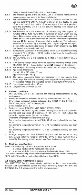
8.2 Voltage measuring
Do not exceed the maximum permitted voltage with respect to earth potential! Electrical danger!
The highest voltage which may be applied to the jacks,- COM socket K- jack for V, Ω and Lof the BENNING CM 5-1 against ground, amounts to 600 V CAT IV/ 1000 V CAT III.
- Switch the BENNING CM 5-1 on by means of the key (grey) J.- The black safety measuring lead has to be contacted with the COM jack K
on the BENNING CM 5-1.- The red safety measuring lead has to be connected to the jack for V, Ω and
L on the BENNING CM 5-1.- Bring the safety measuring leads into contact with the measuring points.- On the digital display , the AUTOTEST function is shown by the
„AutoSense“ symbol 4. It automatically determines the required measuring function (voltage) and the ideal measuring range.
BENNING CM 5-109/ 2009 16
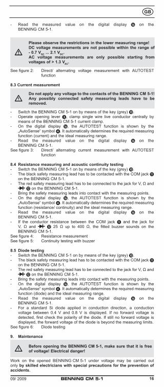
- Read the measured value on the digital display on the BENNING CM 5-1.
Please observe the restrictions in the lower measuring range!DC voltage measurements are not possible within the range of - 0.7 VDC ... 2.1 VDC.AC voltage measurements are only possible starting from voltages of > 1.3 VAC.
See figure 2: Direct/ alternating voltage measurement with AUTOTEST function
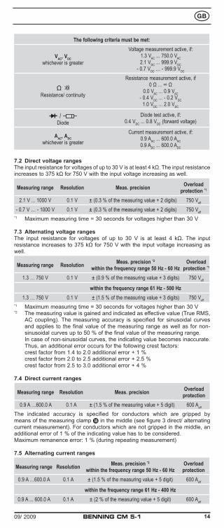
8.3 Current measurement
Do not apply any voltage to the contacts of the BENNING CM 5-1! Any possibly connected safety measuring leads have to be removed.
- Switch the BENNING CM 5-1 on by means of the key (grey) J.- Operate opening lever 3, clamp single wire live conductor centrally by
means of the BENNING CM 5-1 current clamp.- On the digital display , the AUTOTEST function is shown by the
„AutoSense“ symbol 4. It automatically determines the required measuring function (current) and the ideal measuring range.
- Read the measured value on the digital display on the BENNING CM 5-1.
See figure 3: Direct/ alternating current measurement with AUTOTEST function
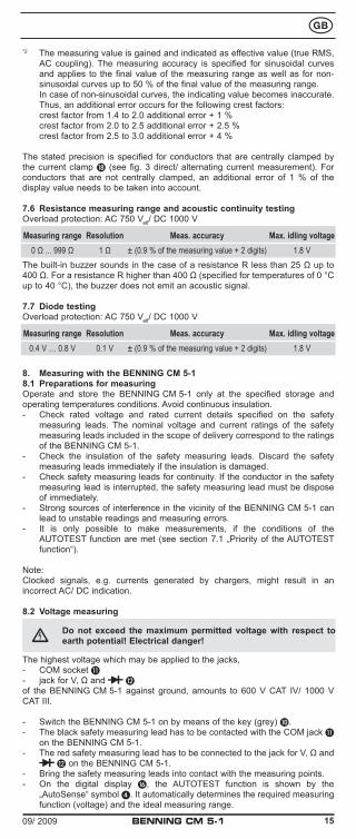
8.4 Resistance measuring and acoustic continuity testing- Switch the BENNING CM 5-1 on by means of the key (grey) J.- The black safety measuring lead has to be contacted with the COM jack K
on the BENNING CM 5-1.- The red safety measuring lead has to be connected to the jack for V, Ω and
L on the BENNING CM 5-1.- Bring the safety measuring leads into contact with the measuring points.- On the digital display , the AUTOTEST function is shown by the
„AutoSense“ symbol 4. It automatically determines the required measuring function (resistance/ continuity) and the ideal measuring range.
- Read the measured value on the digital display on the BENNING CM 5-1.
- If the conductor resistance between the COM jack K and the jack for V, Ω and L 25 Ω up to 400 Ω, the fitted buzzer sounds on the BENNING CM 5-1.
See figure 4: Resistance measurementSee figure 5: Continuity testing with buzzer
8.5 Diode testing- Switch the BENNING CM 5-1 on by means of the key (grey) J.- The black safety measuring lead has to be contacted with the COM jack K
on the BENNING CM 5-1.- The red safety measuring lead has to be connected to the jack for V, Ω and
L on the BENNING CM 5-1.- Bring the safety measuring leads into contact with the measuring points.- On the digital display , the AUTOTEST function is shown by the
„AutoSense“ symbol 4. It automatically determines the required measuring function (diode) and the ideal measuring range.
- Read the measured value on the digital display on the BENNING CM 5-1.
- For a standard Si diode applied in conduction direction, a conduction voltage between 0.4 V and 0.8 V is displayed. If no forward voltage is detected, first check the polarity of the diode. If still no forward voltage is displayed, the forward voltage of the diode is beyond the measuring limits.
See figure 6: Diode testing
9. Maintenance
Before opening the BENNING CM 5-1, make sure that it is free of voltage! Electrical danger!
Work on the opened BENNING CM 5-1 under voltage may be carried out only by skilled electricians with special precautions for the prevention of accidents.
BENNING CM 5-109/ 2009 17
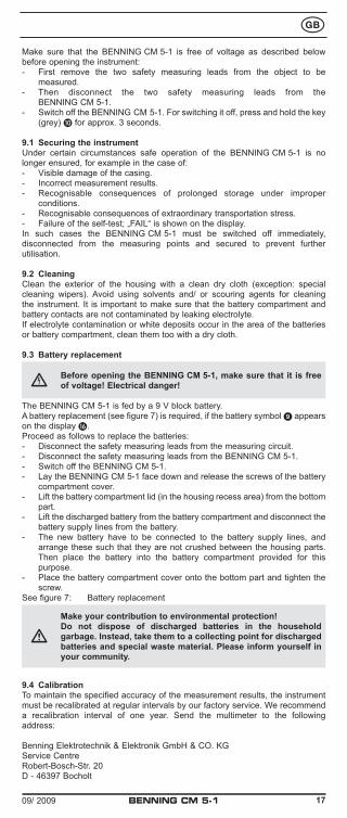
Make sure that the BENNING CM 5-1 is free of voltage as described below before opening the instrument:- First remove the two safety measuring leads from the object to be
measured.- Then disconnect the two safety measuring leads from the
BENNING CM 5-1.- Switch off the BENNING CM 5-1. For switching it off, press and hold the key
(grey) J for approx. 3 seconds.
9.1 Securing the instrumentUnder certain circumstances safe operation of the BENNING CM 5-1 is no longer ensured, for example in the case of:- Visible damage of the casing.- Incorrect measurement results.- Recognisable consequences of prolonged storage under improper
conditions.- Recognisable consequences of extraordinary transportation stress.- Failure of the self-test; „FAIL“ is shown on the display.In such cases the BENNING CM 5-1 must be switched off immediately, disconnected from the measuring points and secured to prevent further utilisation.
9.2 CleaningClean the exterior of the housing with a clean dry cloth (exception: special cleaning wipers). Avoid using solvents and/ or scouring agents for cleaning the instrument. It is important to make sure that the battery compartment and battery contacts are not contaminated by leaking electrolyte.If electrolyte contamination or white deposits occur in the area of the batteries or battery compartment, clean them too with a dry cloth.
9.3 Battery replacement
Before opening the BENNING CM 5-1, make sure that it is free of voltage! Electrical danger!
The BENNING CM 5-1 is fed by a 9 V block battery.A battery replacement (see figure 7) is required, if the battery symbol 9 appears on the display .Proceed as follows to replace the batteries:- Disconnect the safety measuring leads from the measuring circuit.- Disconnect the safety measuring leads from the BENNING CM 5-1.- Switch off the BENNING CM 5-1.- Lay the BENNING CM 5-1 face down and release the screws of the battery
compartment cover.- Lift the battery compartment lid (in the housing recess area) from the bottom
part.- Lift the discharged battery from the battery compartment and disconnect the
battery supply lines from the battery.- The new battery have to be connected to the battery supply lines, and
arrange these such that they are not crushed between the housing parts. Then place the battery into the battery compartment provided for this purpose.
- Place the battery compartment cover onto the bottom part and tighten the screw.
See figure 7: Battery replacement
Make your contribution to environmental protection!Do not dispose of discharged batteries in the household garbage. Instead, take them to a collecting point for discharged batteries and special waste material. Please inform yourself in your community.
9.4 CalibrationTo maintain the specified accuracy of the measurement results, the instrument must be recalibrated at regular intervals by our factory service. We recommend a recalibration interval of one year. Send the multimeter to the following address:
Benning Elektrotechnik & Elektronik GmbH & CO. KGService CentreRobert-Bosch-Str. 20D - 46397 Bocholt
BENNING CM 5-109/ 2009 18
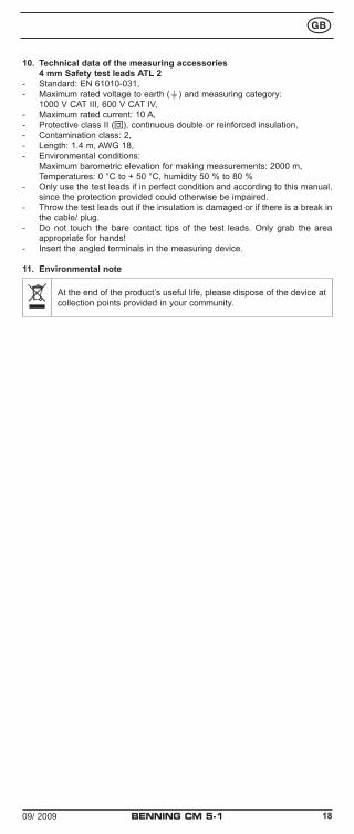
10. Technical data of the measuring accessories 4 mm Safety test leads ATL 2- Standard: EN 61010-031,- Maximum rated voltage to earth () and measuring category: 1000 V CAT III, 600 V CAT IV,- Maximum rated current: 10 A,- Protective class II (), continuous double or reinforced insulation,- Contamination class: 2,- Length: 1.4 m, AWG 18,- Environmental conditions: Maximum barometric elevation for making measurements: 2000 m, Temperatures: 0 °C to + 50 °C, humidity 50 % to 80 %- Only use the test leads if in perfect condition and according to this manual,
since the protection provided could otherwise be impaired.- Throw the test leads out if the insulation is damaged or if there is a break in
the cable/ plug.- Do not touch the bare contact tips of the test leads. Only grab the area
appropriate for hands!- Insert the angled terminals in the measuring device.
11. Environmental note
At the end of the product’s useful life, please dispose of the device at collection points provided in your community.

Benning Elektrotechnik & Elektronik GmbH & Co. KGMünsterstraße 135 - 137
D - 46397 BocholtPhone: +49 (0) 2871 - 93 - 0 • Fax: +49 (0) 2871 - 93 - 429
www.benning.de • E-Mail: [email protected]