Automatic Tuning Machines for SRF Cavities Ruben Carcagno On behalf of the DESY, Fermilab, and KEK...
26
Automatic Tuning Machines for SRF Cavities Ruben Carcagno On behalf of the DESY, Fermilab, and KEK collaboration All Experimenters Meeting October 4, 2010 10/4/2010 1 Cavity Tuning Machines
-
Upload
candice-jordan -
Category
Documents
-
view
220 -
download
2
Transcript of Automatic Tuning Machines for SRF Cavities Ruben Carcagno On behalf of the DESY, Fermilab, and KEK...

Automatic Tuning Machines for SRF Cavities
Ruben CarcagnoOn behalf of the DESY, Fermilab, and KEK
collaboration
All Experimenters Meeting
October 4, 2010
10/4/2010 1Cavity Tuning Machines
Tuning Fundamentals
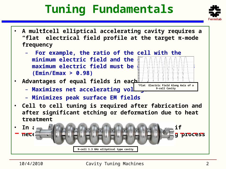
• A multicell elliptical accelerating cavity requires a “flat” electrical field profile at the target π-mode frequency
– For example, the ratio of the cell with the minimum electric field and the cell with the maximum electric field must be greater than 0.98 (Emin/Emax > 0.98)
• Advantages of equal fields in each cell:
– Maximizes net accelerating voltage
– Minimizes peak surface EM fields
• Cell to cell tuning is required after fabrication and after significant etching or deformation due to heat treatment
• In addition, the cavity must be straight and if necessary it must be aligned during the tuning process
10/4/2010 Cavity Tuning Machines 2
“Flat” Electric Field Along Axis of a 9-cell Cavity
9-cell 1.3 GHz elliptical type cavity

Tuning and Alignment Actions
• An electrical model is used to predict the π-mode frequency change needed for each cell to achieve the target π-mode frequency with a flat electric field• The π-mode frequency is changed by changing a cell’s capacitance by squeezing
or stretching the cell
• For a 9-cell cavity, typical change in “d” is < ±1 mm for each cell
• A mechanical model is used to predict the bending angle at each cell to align the cavity• Bending can be done by applying
differential pressure on a cell
10/4/2010 Cavity Tuning Machines 3
d
AC
mm
kHz
d
f300
π-mode frequency change sensitivity to cell dimensional
change for a 9-cell 1.3 GHz cavity
Cell capacitance changed by mechanically squeezing or
stretching cell
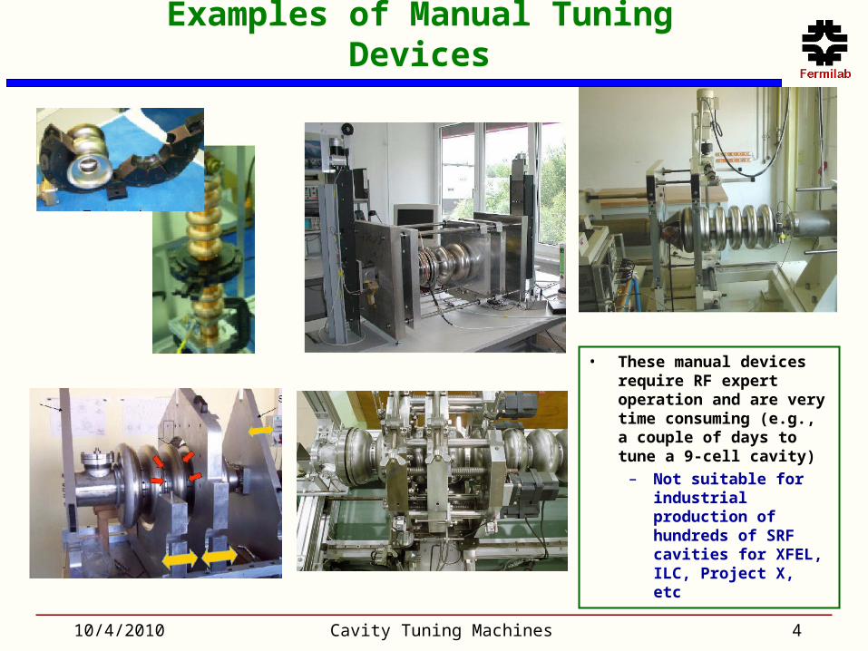
Examples of Manual Tuning Devices
10/4/2010 Cavity Tuning Machines 4
• These manual devices require RF expert operation and are very time consuming (e.g., a couple of days to tune a 9-cell cavity)
– Not suitable for industrial production of hundreds of SRF cavities for XFEL, ILC, Project X, etc

Old DESY tuning machine
• An old tuning machine from DESY provides the basis for an automatic design
• Several modifications and improvements were needed to overcome:
– Obsolete components– Partial automation– Unsupported, fragmented software– Lack of documentation– RF expert operation– Not designed for industrial use
10/4/2010 Cavity Tuning Machines 5
FNAL, DESY, and KEK Collaboration
10/4/2010 Cavity Tuning Machines 6

MOU highlights
• Fabricate four automatic tuning machines for 9-cell TESLA type cavities– Two for DESY to support XFEL cavity production– One for KEK– One for Fermilab
• DESY responsible for the design and fabrication of complete mechanical assemblies (including electrical devices)
• Fermilab responsible for the control system, consisting of a complete set of electronics and control software
• KEK purchase one machine
10/4/2010 Cavity Tuning Machines 7
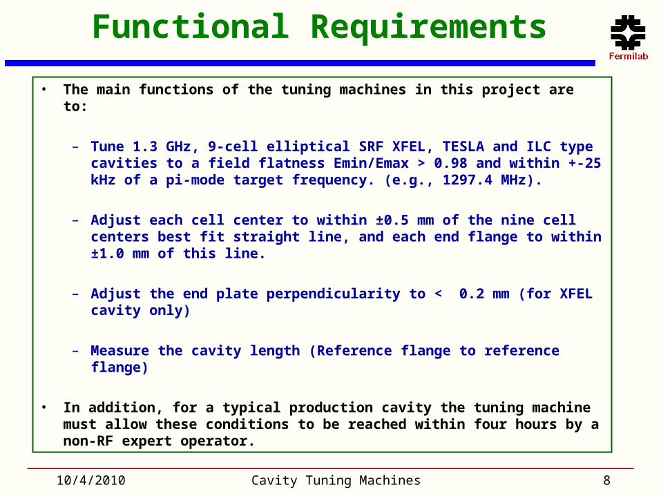
Functional Requirements
• The main functions of the tuning machines in this project are to:
– Tune 1.3 GHz, 9-cell elliptical SRF XFEL, TESLA and ILC type cavities to a
field flatness Emin/Emax > 0.98 and within +-25 kHz of a pi-mode target frequency. (e.g., 1297.4 MHz).
– Adjust each cell center to within ±0.5 mm of the nine cell centers best fit
straight line, and each end flange to within ±1.0 mm of this line.
– Adjust the end plate perpendicularity to < 0.2 mm (for XFEL cavity only)
– Measure the cavity length (Reference flange to reference flange)
• In addition, for a typical production cavity the tuning machine must allow
these conditions to be reached within four hours by a non-RF expert operator.
10/4/2010 Cavity Tuning Machines 8
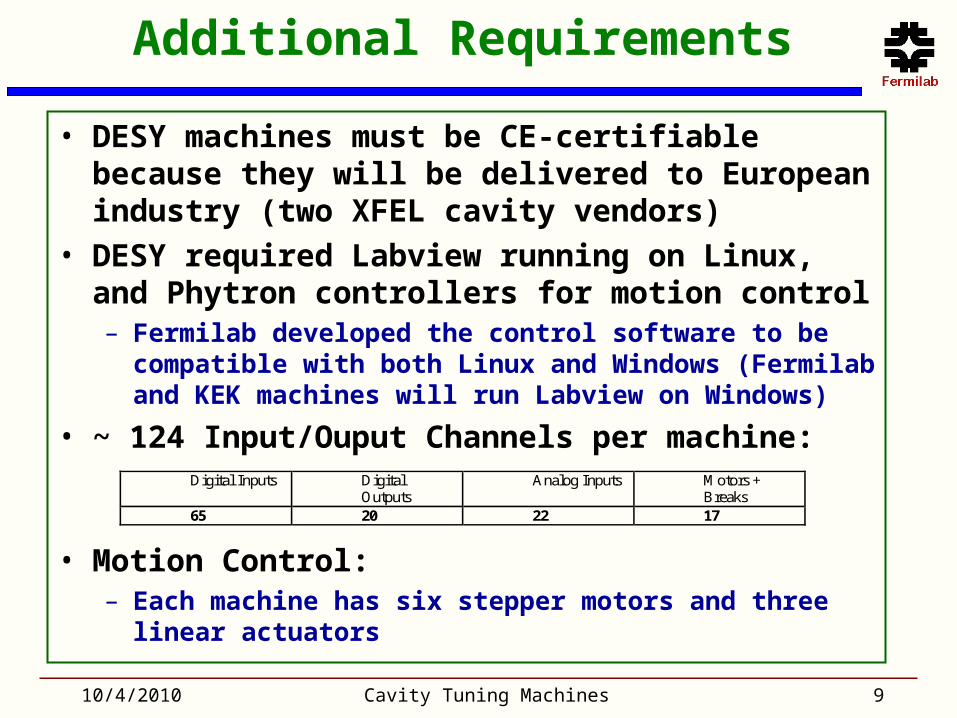
Additional Requirements
• DESY machines must be CE-certifiable because they will be delivered to European industry (two XFEL cavity vendors)
• DESY required Labview running on Linux, and Phytron controllers for motion control– Fermilab developed the control software to be compatible
with both Linux and Windows (Fermilab and KEK machines will run Labview on Windows)
• ~ 124 Input/Ouput Channels per machine:
• Motion Control:– Each machine has six stepper motors and three linear
actuators
10/4/2010 Cavity Tuning Machines 9
Digital Inputs Digital Outputs
Analog Inputs Motors + Breaks
65 20 22 17

Cavity Tuning Machines Project
• MOU completed: all four machines fabricated, commissioned, and delivered
• Next Phase:– Maintenance and improvements– Support for KEK machine re-
assembly and re-commissioning at KEK (Nov. 2010)
10Cavity Tuning Machines10/4/2010
Fermilab machine after commissioning in IB4 – Tuned ~ 6 cavities to date
One of two DESY machines after commissioning at DESY – Tuned ~ 5 cavities to date
KEK machine commissioned at Fermilab and ready for shipment
– Now at KEK

Tuning Machine Overview
10/4/2010 Cavity Tuning Machines 11
Tuning Frame with three independent jaws
Eccentricity Measurement System
Bead pull motor
Base Frame motor
Tuning Jaws (x6)
Jaws Motor (x3)
Jaws Linear Actuator (x3)
Protective Shields (x10)

Control Software (by FNAL)
12Cavity Tuning Machines10/4/2010
• Labview (1184 VIs), Matlab (electrical and mechanical models), Phytron script (motion control)
• Support expert manual mode, automatic mode, and machine maintenance and calibration mode

Control Racks (by FNAL)
13Cavity Tuning Machines10/4/2010
Control Racks (1 per machine) Custom Control Electronics
Manual Control Box
DAQ Box
Emergency Trip Box
Linear Actuator Drive Box
Motion Inhibit Box
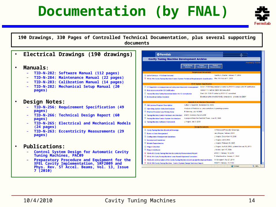
Documentation (by FNAL)
• Electrical Drawings (190 drawings)
• Manuals:– TID-N-282: Software Manual (112 pages)– TID-N-284: Maintenance Manual (22 pages)– TID-N-283: Calibration Manual (14 pages)– TID-N-282: Mechanical Setup Manual (20 pages)
• Design Notes:– TID-N-256: Requirement Specification (49
pages)– TID-N-266: Technical Design Report (60 pages)– TID-N-265: Electrical and Mechanical Models
(24 pages)– TID-N-263: Eccentricity Measurements (29
pages)
• Publications:– Control System Design for Automatic Cavity
Tuning Machines, PAC09– Preparatory Procedure and Equipment for the
XFEL Cavity Implementation, SRF2009 and Phys. Rev. ST Accel. Beams, Vol. 13, Issue 7 (2010)
10/4/2010 Cavity Tuning Machines 14
190 Drawings, 330 Pages of Controlled Technical Documentation, plus several supporting documents
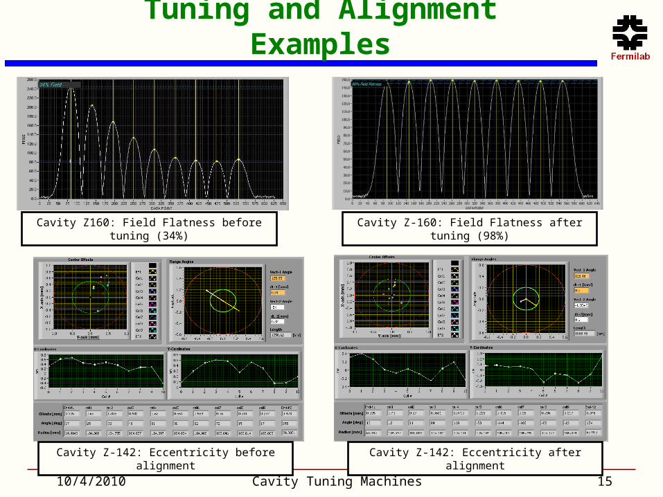
Tuning and Alignment Examples
10/4/2010 Cavity Tuning Machines 15
Cavity Z160: Field Flatness before tuning (34%) Cavity Z-160: Field Flatness after tuning (98%)
Cavity Z-142: Eccentricity before alignment Cavity Z-142: Eccentricity after alignment
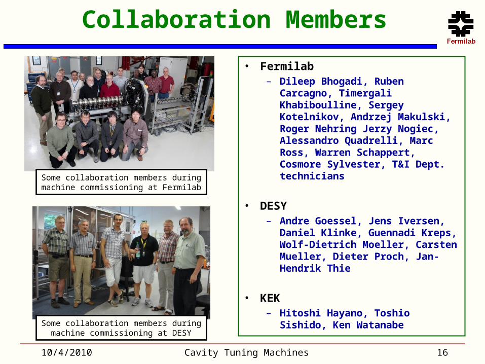
Collaboration Members
• Fermilab– Dileep Bhogadi, Ruben Carcagno,
Timergali Khabiboulline, Sergey Kotelnikov, Andrzej Makulski, Roger Nehring Jerzy Nogiec, Alessandro Quadrelli, Marc Ross, Warren Schappert, Cosmore Sylvester, T&I Dept. technicians
• DESY– Andre Goessel, Jens Iversen,
Daniel Klinke, Guennadi Kreps, Wolf-Dietrich Moeller, Carsten Mueller, Dieter Proch, Jan-Hendrik Thie
• KEK – Hitoshi Hayano, Toshio Sishido,
Ken Watanabe
10/4/2010 Cavity Tuning Machines 16
Some collaboration members during machine commissioning at Fermilab
Some collaboration members during machine commissioning at DESY

Backup Slides (9 slides)
• Spectrum Measurements• Measuring Electric Field Profile• Electric Model• Eccentricity Measurements• Reference Flange Perpendicularity Measurements• Cavity Alignment Laser• Mechanical Model• Tuning and Aligning the Cavity• CE Certification
10/4/2010 Cavity Tuning Machines 17

Spectrum Measurement
• A multicell cavity is a structure with multiple resonators (cells) coupled together.
– There are multiple modes of excitation of the full structure
– The preferred accelerating mode is the “π-mode”
• Fields in neighboring cells are π radians out of phase with each other and the particle crosses a cell in one-half an rf period
• A Network Analyzer is used to measure the 9 modes of a 9-cell cavity
– The highest frequency mode is the π-mode
10/4/2010 Cavity Tuning Machines 18
Electric Field Lines of the π-mode of a 9-cell cavity
9 excitation modes of a 9-cell cavity. The highest frequency mode is the π-mode
π-mode
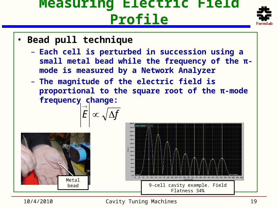
Measuring Electric Field Profile
• Bead pull technique– Each cell is perturbed in succession using a small metal
bead while the frequency of the π-mode is measured by a Network Analyzer
– The magnitude of the electric field is proportional to the square root of the π-mode frequency change:
10/4/2010 Cavity Tuning Machines 19
fE
9-cell cavity example. Field Flatness 34%Metal bead

Electric Model
10/4/2010 Cavity Tuning Machines 20
• Based on bead pull data, an electric model calculates the π-mode frequency change for each cell necessary to achieve the target π-mode frequency with a flat field
0111
...
0111
0111
11
11
2111
ICi
ICi
IICi
IICi
ICi
IICi
IICi
ICi
ILiCi
bnnn
k
jjk
jjjb
kb
Model input: target frequency, modal frequencies, sq. rt. frequency shifts during bead pull at each mode
Model output: π-mode target frequencies as each cell is tuned in turn
Bead pull measurements Spectrum measurements
n-pole lumped parameter model of coupled LC oscillators

10/4/2010 Cavity Tuning Machines 21
Eccentricity Measurements
Calibration with precisely machined “dummy” cavity
XFEL: cell centers within ±0.5 mm, end flange centers within ±1 mm
10/4/2010 Cavity Tuning Machines 22
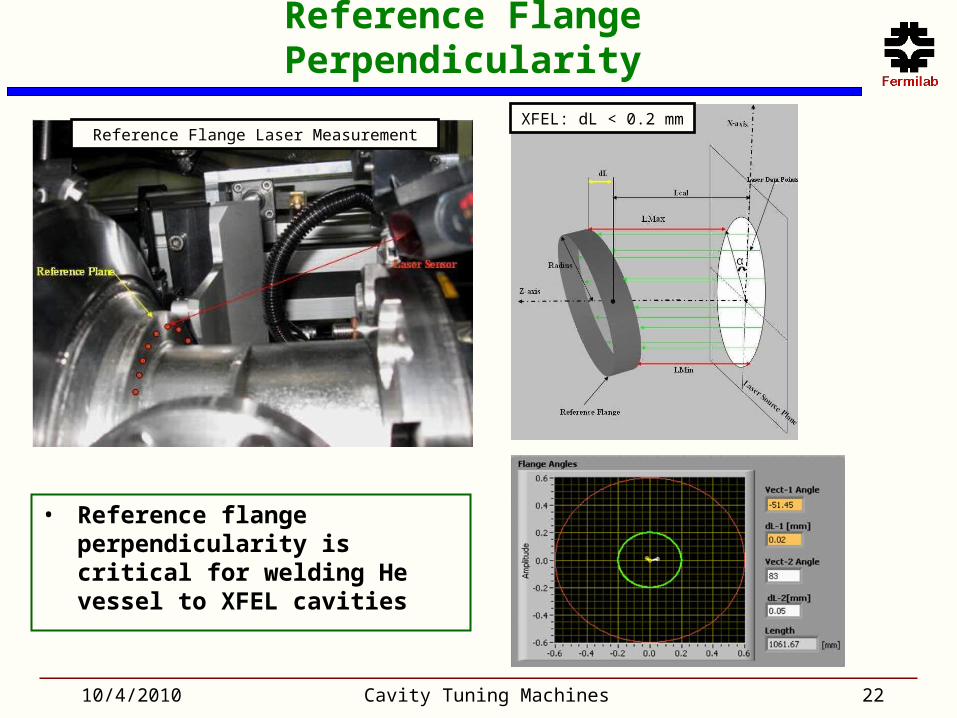
Reference Flange Perpendicularity
• Reference flange perpendicularity is critical for welding He vessel to XFEL cavities
Reference Flange Laser MeasurementXFEL: dL < 0.2 mm

10/4/2010 Cavity Tuning Machines 23
Cavity Alignment Laser
• Laser spot on camera tracks cavity bending while three independent jaws squeeze or stretch a cell
Mirror
Camera
Laser
Digitized Laser Spot Trajectory
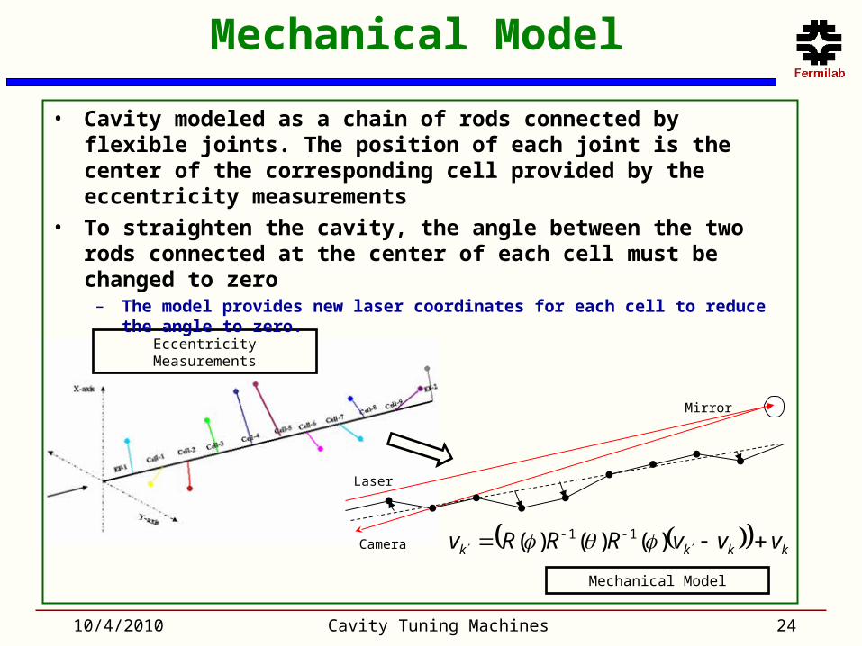
Mechanical Model
10/4/2010 Cavity Tuning Machines 24
Laser
Mirror
Camera kkkk vvvRRRv
)()()( 11
Eccentricity Measurements
Mechanical Model
• Cavity modeled as a chain of rods connected by flexible joints. The position of each joint is the center of the corresponding cell provided by the eccentricity measurements
• To straighten the cavity, the angle between the two rods connected at the center of each cell must be changed to zero
– The model provides new laser coordinates for each cell to reduce the angle to zero.

Tuning and Aligning the Cavity
• The electrical and mechanical models provide π-mode frequency change and new laser coordinate setpoints for each cell
• An automatic tuning and alignment algorithm provides motion instruction to the three independent jaws using π-mode frequency and laser spot motion feedback.
10/4/2010 Cavity Tuning Machines 25

CE Certification
• Required by European industrial use
• DESY hired CE consultant who recommended and reviewed personnel protection safety features
• Must comply with EN ISO 13849-1, Category 3
– Fail safe design, with no single point of failure
– 30 power lines to be opened in an emergency condition with CE-compliant relays
10/4/2010 Cavity Tuning Machines 26
Access door solenoid-latching device
Enabling switch to allow
access to operating
machine for maintenanceMachine Guard: enclosure fence with
access doors (for DESY machines only)Redundant relays to de-energize all nine motors