as a component in the electric power system · as a component in the electric power system d e dt...
23
23. september 2011 1 Lecture 05 Power Engineering - Egill Benedikt Hreinsson The synchronous machine as a component in the electric power system d e dt Φ =
Transcript of as a component in the electric power system · as a component in the electric power system d e dt...
23. september 2011
1Lecture 05 Power Engineering - Egill Benedikt Hreinsson
The synchronous machineas a component in the electric power
system
dedtΦ
=
23. september 2011
2Lecture 05 Power Engineering - Egill Benedikt Hreinsson
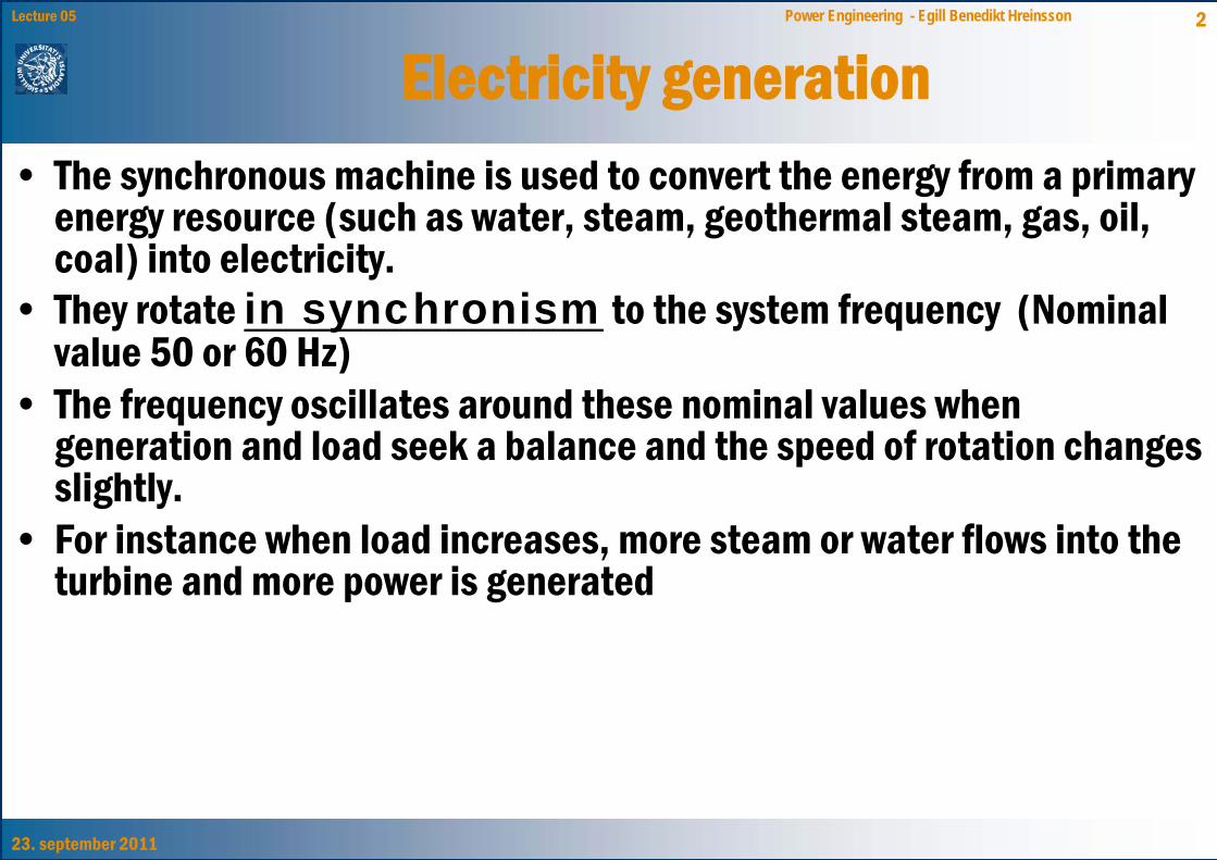
Electricity generation• The synchronous machine is used to convert the energy from a primary
energy resource (such as water, steam, geothermal steam, gas, oil, coal) into electricity.
• They rotate in synchronism to the system frequency (Nominal value 50 or 60 Hz)
• The frequency oscillates around these nominal values when generation and load seek a balance and the speed of rotation changes slightly.
• For instance when load increases, more steam or water flows into the turbine and more power is generated
23. september 2011
3Lecture 05 Power Engineering - Egill Benedikt Hreinsson
The generator an turbine are mechanically connected to each other
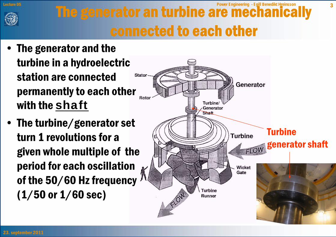
• The generator and the turbine in a hydroelectric station are connected permanently to each other with the shaft
• The turbine/generator set turn 1 revolutions for a given whole multiple of the period for each oscillation of the 50/60 Hz frequency (1/50 or 1/60 sec)
Turbine generator shaft
23. september 2011
4Lecture 05 Power Engineering - Egill Benedikt Hreinsson
The synchronous machine in the power system
• Therefore the synchronous machine is used almost exclusively to generate AC voltage and current in the power system. Other possibilities are for instance induction machines in wind generators.
• The primary parts of the machine are:– The Stator, or the stationary part of the machine. The stator
is permanently connected to the poaer system (3 phases)– The Rotor or the moving part of the machine is connected
with a shaft to the turbine. The excitation is an electrical connection to a DC source to magnetize the rotor.
• Round rotor: 1800-3600 rpm (2-4 poles)• Salient pole rotor: 100-300 rpm. (many poles)
23. september 2011
5Lecture 05 Power Engineering - Egill Benedikt HreinssonThe characteristics of thesynchronous machine
• We have field windings on the rotor and armature windings on the stator.
• Double magnetization (Stator and rotor)• Excitation with a DC • Fixed speed of rotation
– The magnetic field in the air gap rotates with the same speed as the rotor
• Generates or consumes reactive power• Applications:
– In an electric power system as a generator – In industry where a constant rotational speed is needed
23. september 2011
6Lecture 05 Power Engineering - Egill Benedikt Hreinsson
The synchronous machine – What does the rotor look like?
• Round rotor– Uniform air gap – distributed windings– The reluctance in the stator circuit is independent of rotor
position– High rotational speed– Used as a generator with gas turbines or steam turbines
• Salient pole rotor– Non-uniform air gap – concentrated windings on the pole– The reluctance in the stator circuit is dependent of rotor position– Slow speed of rotation– Used as a generator with hydroelectric turbines
23. september 2011
7Lecture 05 Power Engineering - Egill Benedikt Hreinsson
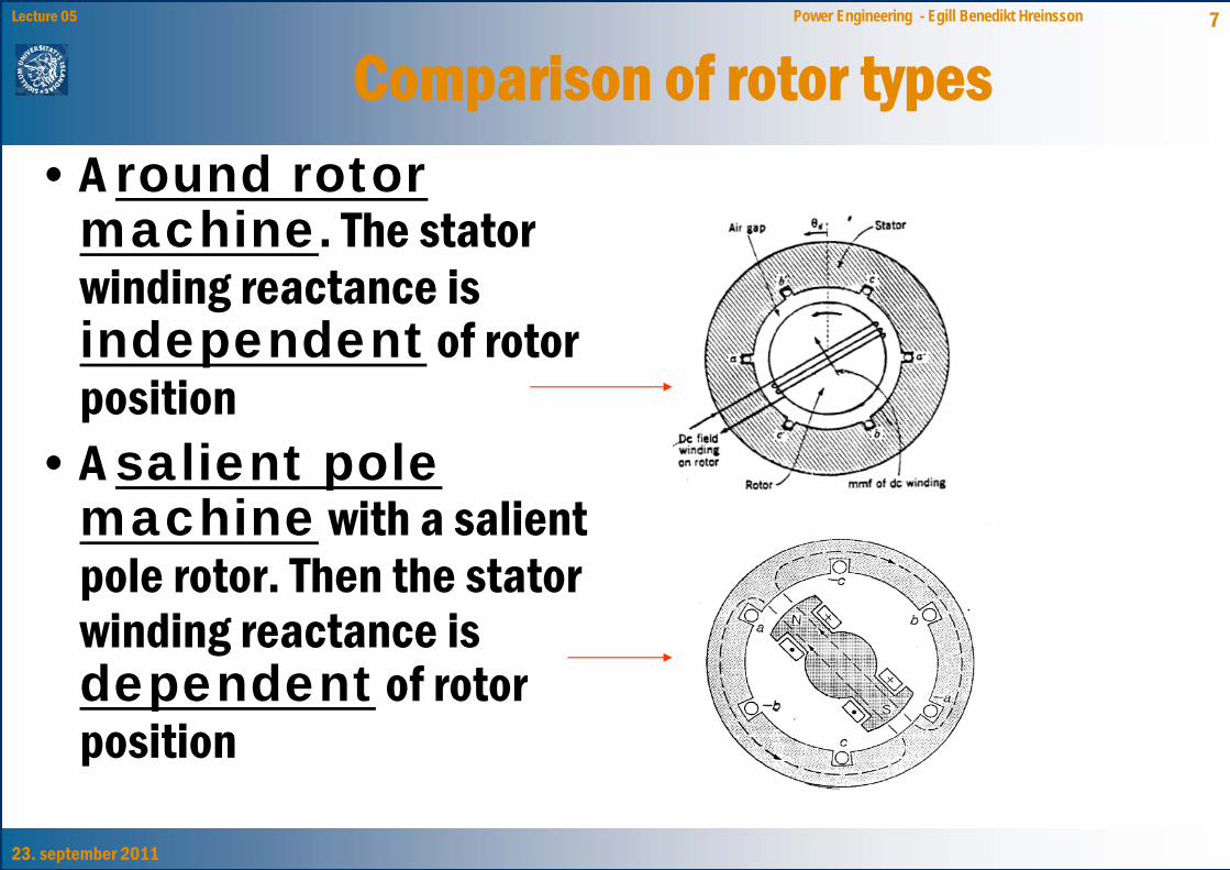
Comparison of rotor types• A round rotor
machine. The stator winding reactance is independent of rotor position
• A salient pole machine with a salient pole rotor. Then the stator winding reactance is dependent of rotor position
23. september 2011
8Lecture 05 Power Engineering - Egill Benedikt Hreinsson
The 3-phase circuit for a synchronous machine
rotor stator
a
b
c
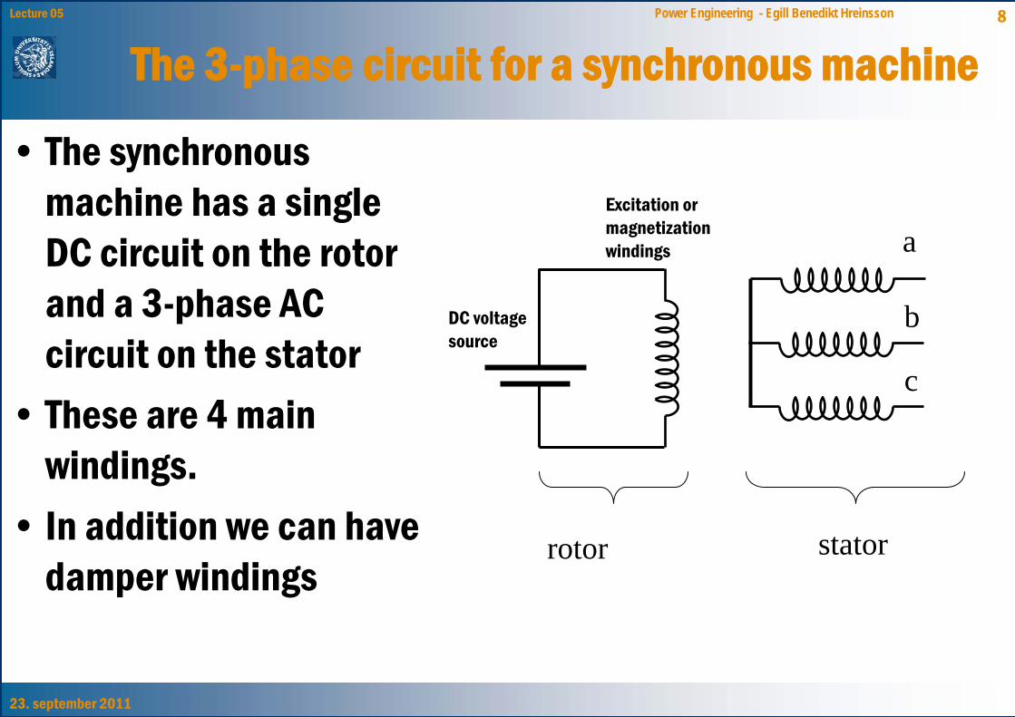
• The synchronous machine has a single DC circuit on the rotor and a 3-phase AC circuit on the stator
• These are 4 main windings.
• In addition we can have damper windings
DC voltage source
Excitation or magnetization windings
23. september 2011
9Lecture 05 Power Engineering - Egill Benedikt Hreinsson
Synchronous machine in the electric power system
• The most common sizes of synchronous machines are 30-1500 MVA
• We often use another name: “alternator”• The windings:
– The stator windings are 3-phase and connected to an external power system
– The rotor windings, also called field windings because they create the machine magnetic field (These are closed loop windings connected to a separate DC source)
– Damper windings (closed loop and not connected to any external source)
23. september 2011
10Lecture 05 Power Engineering - Egill Benedikt Hreinsson
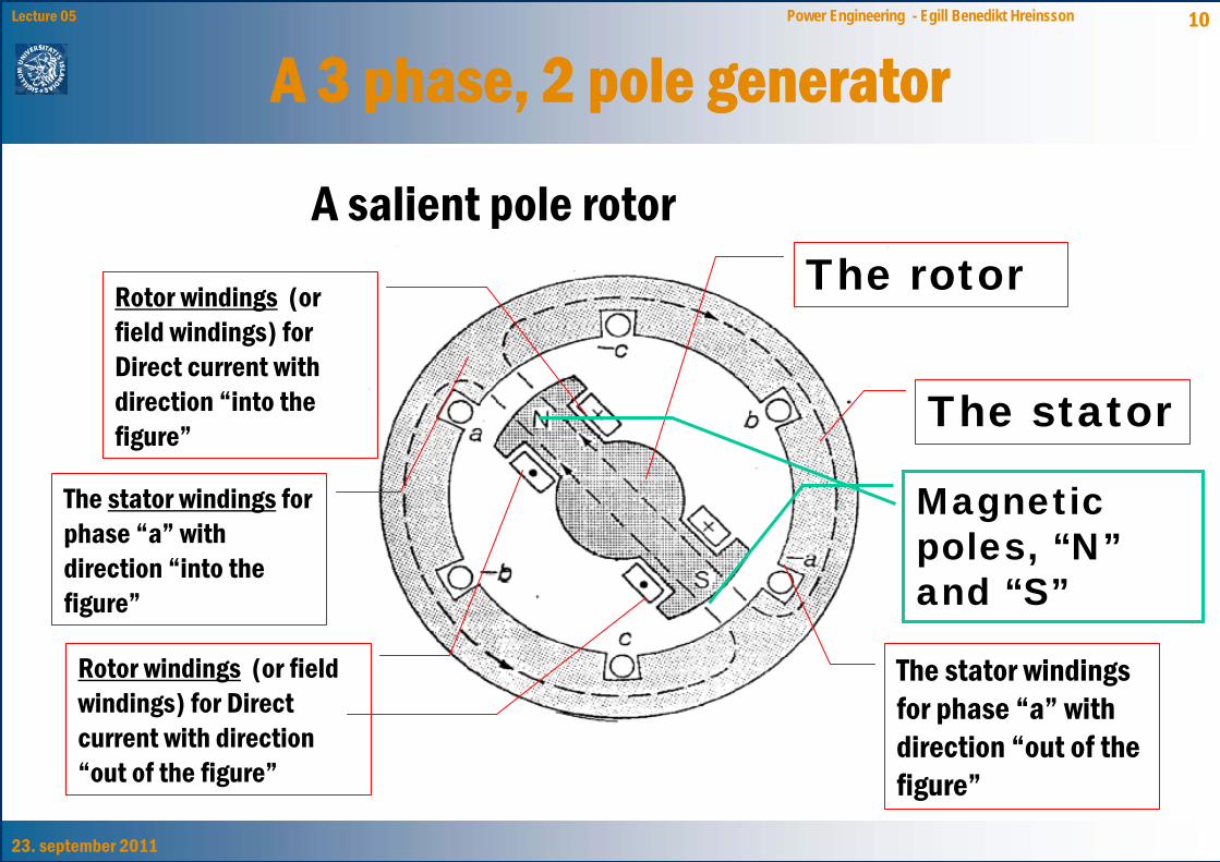
A 3 phase, 2 pole generator
The stator windings for phase “a” with direction “into the figure”
The stator windings for phase “a” with direction “out of the figure”
The stator
The rotorRotor windings (or field windings) for Direct current with direction “into the figure”
Rotor windings (or field windings) for Direct current with direction “out of the figure”
Magnetic poles, “N”and “S”
A salient pole rotor
23. september 2011
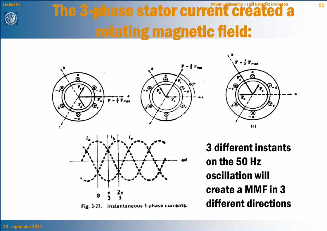
11Lecture 05 Power Engineering - Egill Benedikt HreinssonThe 3-phase stator current created a rotating magnetic field:
3 different instants on the 50 Hz oscillation will create a MMF in 3 different directions
23. september 2011
12Lecture 05 Power Engineering - Egill Benedikt Hreinsson
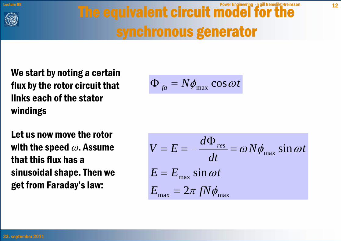
The equivalent circuit model for the synchronous generator
Let us now move the rotor with the speed ω. Assume that this flux has a sinusoidal shape. Then we get from Faraday’s law:
max
max
max max
sin
sin2
resdV E N tdt
E E tE fN
ω φ ω
ωπ φ
Φ= = − =
==
max cosfa N tφ ωΦ =We start by noting a certain flux by the rotor circuit that links each of the stator windings
23. september 2011
13Lecture 05 Power Engineering - Egill Benedikt Hreinsson
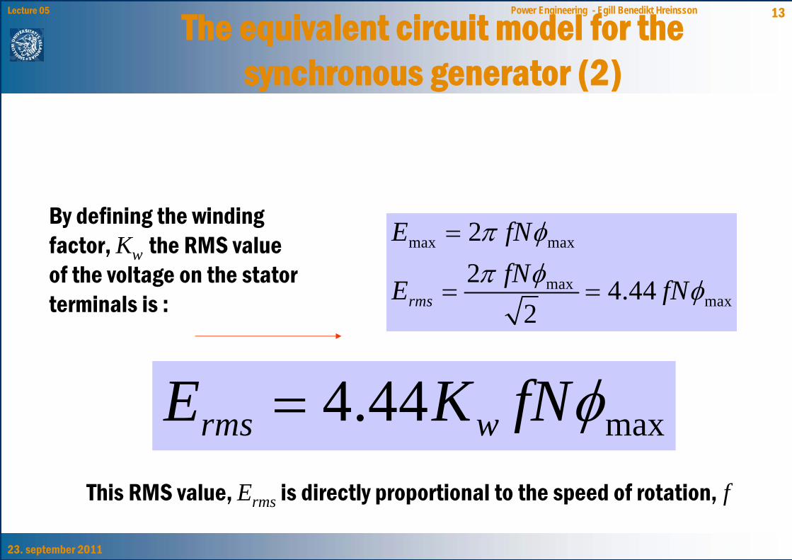
The equivalent circuit model for the synchronous generator (2)
max max
maxmax
22 4.44
2rms
E fNfNE fN
π φπ φ φ
=
= =
By defining the winding factor, Kw the RMS value of the voltage on the stator terminals is :
max4.44rms wE K fNφ=This RMS value, Erms is directly proportional to the speed of rotation, f
23. september 2011
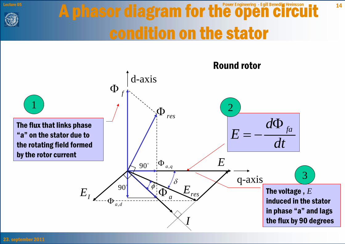
14Lecture 05 Power Engineering - Egill Benedikt HreinssonA phasor diagram for the open circuit condition on the stator
The flux that links phase “a” on the stator due to the rotating field formed by the rotor current
The voltage , E induced in the stator in phase “a” and lags the flux by 90 degrees
dtd
E faΦ−=
1
3
2
Round rotor
I
aΦ resE
E
fΦ
resΦ
IE
d-axis
q-axis
,a dΦ
,a qΦ90
90δφ
23. september 2011
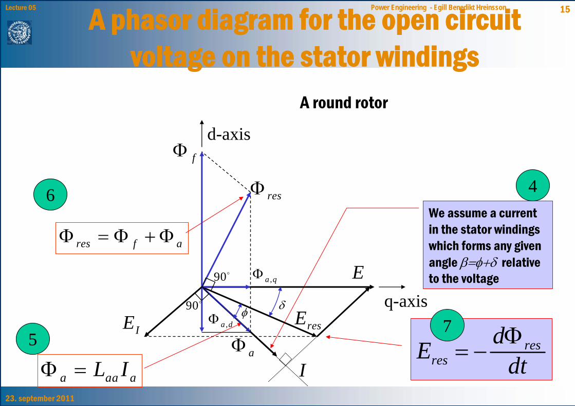
15Lecture 05 Power Engineering - Egill Benedikt HreinssonA phasor diagram for the open circuit voltage on the stator windings
We assume a current in the stator windings which forms any given angle β=φ+δ relative to the voltage
a aa aL IΦ =
res f aΦ = Φ + Φ
dtdE res
resΦ
−=
4
5
6
7
A round rotor
IaΦ
resE
E
fΦ
resΦ
IE
d-axis
q-axis,a dΦ
,a qΦ90
90 δφ
23. september 2011
16Lecture 05 Power Engineering - Egill Benedikt Hreinsson
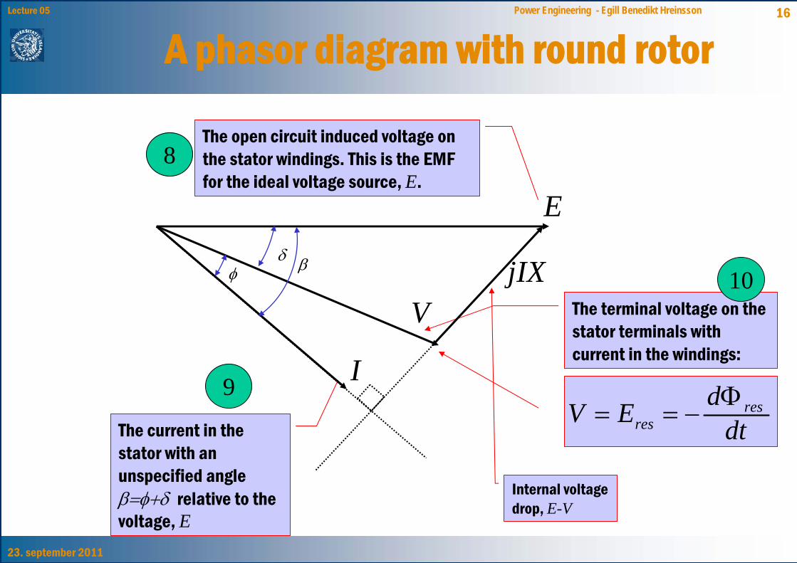
A phasor diagram with round rotor
The current in the stator with an unspecified angle β=φ+δ relative to the voltage, E
dtdEV res
resΦ
−==9
The open circuit induced voltage on the stator windings. This is the EMF for the ideal voltage source, E.
8
The terminal voltage on the stator terminals with current in the windings:
Internal voltage drop, E-V
10
E
V
I
jIXδ
φ β
23. september 2011
17Lecture 05 Power Engineering - Egill Benedikt Hreinsson
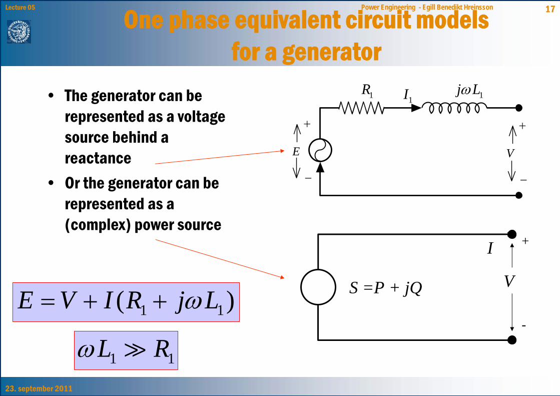
One phase equivalent circuit models for a generator
S =P + jQ V
+
-
I
• The generator can be represented as a voltage source behind a reactance
• Or the generator can be represented as a (complex) power source
E
−
+
1I1R 1j Lω
V
−
+
1 1( )E V I R j Lω= + +
1 1L Rω
23. september 2011
18Lecture 05 Power Engineering - Egill Benedikt Hreinsson
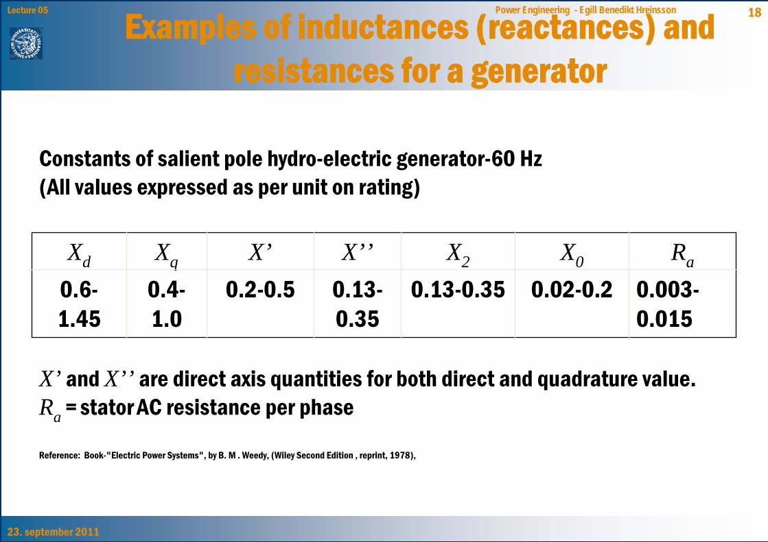
Examples of inductances (reactances) and resistances for a generator
Constants of salient pole hydro-electric generator-60 Hz(All values expressed as per unit on rating)
0.003-0.015
0.02-0.20.13-0.350.13-0.35
0.2-0.50.4-1.0
0.6-1.45
RaX0X2X’’X’XqXd
X’ and X’’ are direct axis quantities for both direct and quadrature value.Ra = stator AC resistance per phase
Reference: Book-"Electric Power Systems", by B. M . Weedy, (Wiley Second Edition , reprint, 1978),
23. september 2011
19Lecture 05 Power Engineering - Egill Benedikt Hreinsson
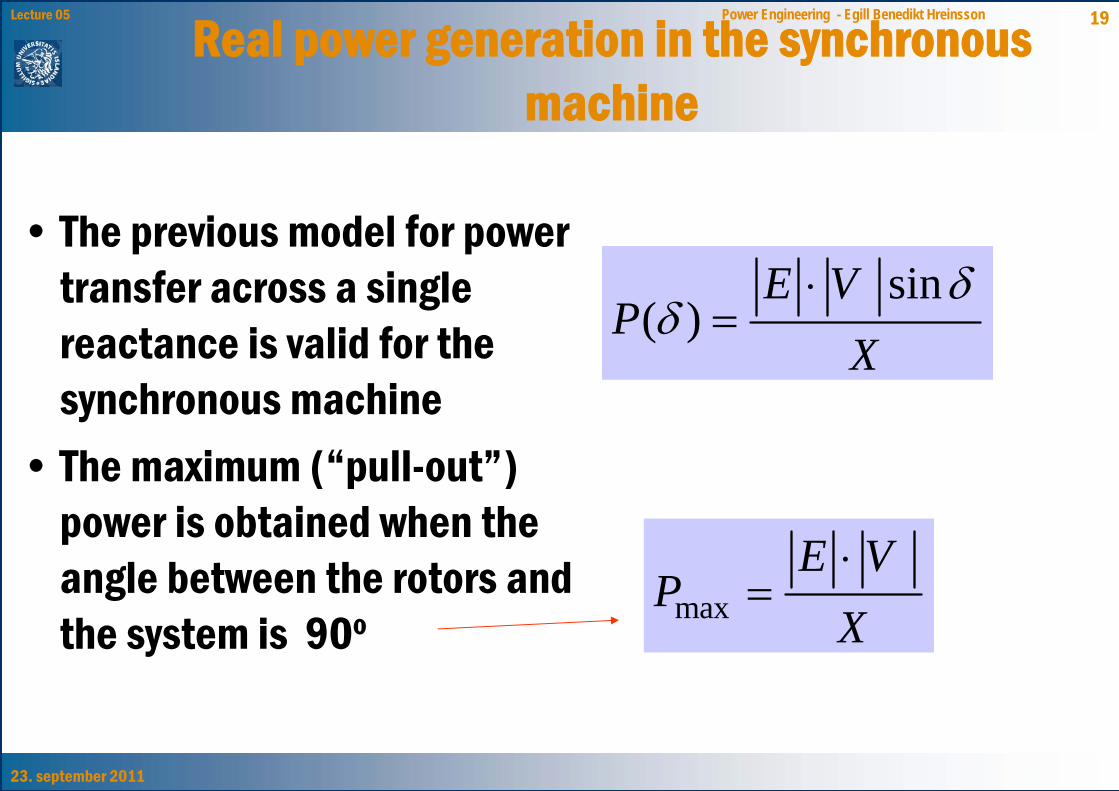
Real power generation in the synchronous machine
sin( )
E VP
Xδ
δ⋅
=
• The previous model for power transfer across a single reactance is valid for the synchronous machine
• The maximum (“pull-out”) power is obtained when the angle between the rotors and the system is 90o max
E VP
X⋅
=
23. september 2011
20Lecture 05 Power Engineering - Egill Benedikt Hreinsson
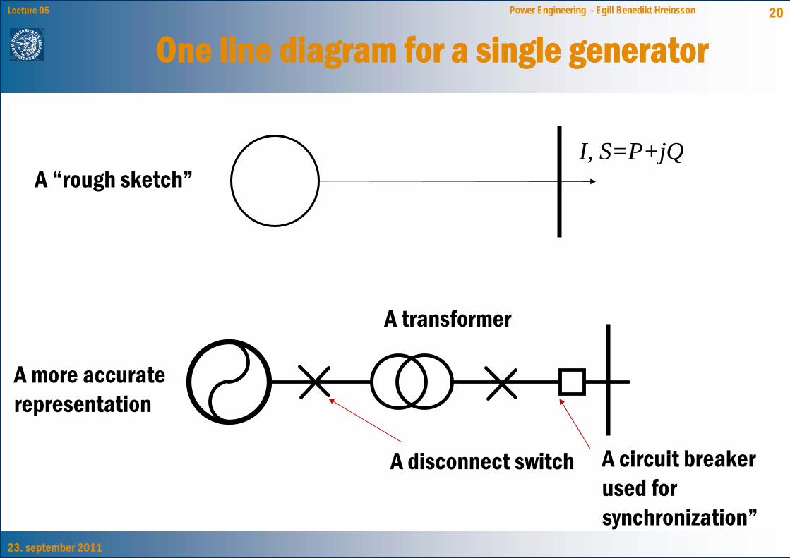
One line diagram for a single generator
I, S=P+jQ
A circuit breaker used for synchronization”
A disconnect switch
A transformer
A “rough sketch”
A more accurate representation
23. september 2011
21Lecture 05 Power Engineering - Egill Benedikt Hreinsson
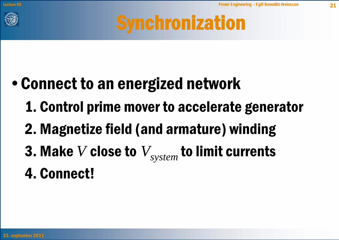
Synchronization
•Connect to an energized network1. Control prime mover to accelerate generator2. Magnetize field (and armature) winding3. Make V close to Vsystem to limit currents4. Connect!
23. september 2011
22Lecture 05 Power Engineering - Egill Benedikt Hreinsson
Synchronization conditions• V close to Vsystem if the voltages have
– Same phase order (abc)– Same frequency– Same magnitude– Same phase
23. september 2011
23Lecture 05 Power Engineering - Egill Benedikt Hreinsson
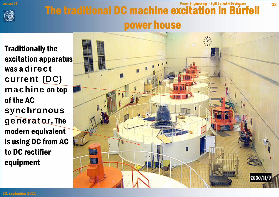
The traditional DC machine excitation in Búrfell power house
Traditionally the excitation apparatus was a direct current (DC) machine on top of the AC synchronous generator. The modern equivalent is using DC from AC to DC rectifier equipment