Σ(r) MVP E(r) Standard deviation of return C A B Expected return % 15% 10%
Upload
vuongxuyenCategory
view
228download
3
Arc Welding: From Process Simulation to Structural Mechanics Part I: Process Simulation with ANSYS CFX Andreas Spille-Kohoff, Dr. CFX Berlin Software GmbH, Germany SYNOPSIS Arc welding and plasma cutting are widely used techniques to join or separate metals. Though these methods have been in use for decades, there is not much theoretical knowledge about the details of the actual physical processes. Significant empirical experience exists, and simulation tools have been used to examine the stress or deformation of the metal from an equivalent heat source representing the influence of the electric arc. Most of this expertise and simulation is limited to well-known standard welding processes. Using simulation for new processes demands the simulation of the process from basic physics, i.e. the arc with electric current, resistive heating and radiation, and the structure, i.e. the microstructure of the metal, its stress and deformation. ANSYS CFX has been used for process simulation, and Virtual Weld Shop, an extension to ANSYS, has been used for prediction of deformations and residual stresses. These simulations have to be coupled, since process simulation gives heat input and weld pool shape into the structural simulation, and structural simulation gives changes of gap width and latent heats from microstructure formation. Their integration into an overall welding simulation tool will be discussed. CFX Berlin shows results of process simulation of arc welding with ANSYS CFX including gas flow, electro-magnetics, arc physics and sheath models. The model was successfully used for the simulation of electric arcs in Gas Tungsten Arc Welding (GTAW), Gas Metal Arc Welding (GMAW), Plasma Arc Welding (PAW) and plasma cutting and spraying. Aims of the simulations are the examination and optimization of arc stability, shielding effect, and heat transfer distribution towards work piece in dependency on geometry and boundary conditions.
1. INTRODUCTION In Gas Metal Arc Welding (GMAW), a metallic wire is automatically fed toward the work piece, e.g. to join two overlapping metal sheets. A shielding gas, typically Argon, blown from the gas nozzle surrounds the wire. Between the tip of the wire and the work piece, an electric
EASC 20094th European Automotive Simulation Conference
Munich, Germany6-7 July 2009
Copyright ANSYS, Inc.
arc ignites and melts both the wire and the work piece material. Molten droplets from the wire fall down onto the weld pool at the surface of the work piece and form the weld seam. In Gas Tungsten Arc Welding and plasma cutting, the wire is replaced by a fixed, unmelted Tungsten electrode. Most of today’s expertise is limited to well-known standard welding processes. However, many applications now are becoming much more complex than these standard processes: - Digitally controlled power supplies allow complex process control with real-time
optimization providing more opportunities than constant-current, constant-voltage or pulsed welding.
- AC welding is becoming popular, but optimization is done by trial and error. - Twin systems with two or even more welding torches allow faster welding, but interaction
between the torches has to be taken into account. - Hybrid systems e.g. with Laser and GMAW torch allow welding over a pre-heated
surface, but again interaction has to be taken into account to find the optimal process parameters.
These new systems must be optimized for the main challenges in welding: • Thinner sheets: Metal sheets are becoming thinner and thinner. The goal in the
automotive industry is to weld thin sheets down to 0.2 mm thickness without destroying corrosion resistance.
EASC 20094th European Automotive Simulation Conference
Munich, Germany6-7 July 2009
Copyright ANSYS, Inc.
• More materials: Aluminum and magnesium are becoming popular in automotive manufacturing but supporting parts still consist of steel. These new materials and their combinations have to be welded quickly and reliably.
• Visually perfect weld: Manual refinishing operations are expensive, so that spatter, holes, zinc layer evaporation and strong deformation have to be avoided.
• Speed: Welding must be fast and robust at all times. For optimal use of such new systems, deep insight into complex welding processes, with their tight non-linear couplings, is essential. CFD simulation with ANSYS CFX software is an important tool to achieve this deep insight: it delivers the required high resolution of all physical quantities - both spatially and temporally; it allows quantification and weighting of each physical effect separately; and it permits changes in geometry, boundary conditions, and material properties to be realized easily. Simpler models are not capable of describing the complex, coupled phenomena, and experimental measurements are difficult in welding because the electric arc temperature can be up to 30,000 K with large amounts of radiation, liquid metal temperatures can be up to 3,000 K, and the entire process is very fast (up to 400 droplets per second).
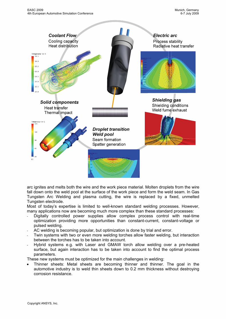
2. PHYSICAL PHENOMENA IN GAS METAL ARC WELDING In modern GMAW torches for automated welding several components and several physical processes are coupled. Whereas simulation of coolant flow, heat conduction through solid components and weld fume exhaust devices (which are becoming more and more important due to additional health requirements) is relatively easy, simulations including the shielding conditions, droplet transition, and the weld pool must take into account an enormously complex combination of physical phenomena:
• Multiphase Flow: Liquid and gas make contact at free surfaces; the multi-component metal (alloy, zinc-coated or with different materials in the work piece and wire) as the liquid phase is interacting with a multi-component gas phase (inert gas with active components like CO2 and ambient gas).
• Surface Effects: While surface tension and adhesion are important for droplet transition, Marangoni convection has a great influence on weld pool depth, i.e. the penetration depth of welding.
• Phase Changes: Effects of melting/ solidification, with latent heat effects and structure formation, and the frequent sudden evaporation of metal have to be captured by appropriate models.
• Radiation: Both the volumetric emission of radiation and its absorption at metal surfaces must be incorporated in the simulation.
• Electro-Magnetics: The energy and momentum in the system are strongly influenced by electro-magnetic effects. The external voltage causes an electric current through the conducting metal and hot gases (plasma). The current generates a magnetic field. The fluid is accelerated by the Lorentz force (the so-called Pinch effect on arc column) and heated by resistive heating. This magneto-hydrodynamics (MHD) has been simulated using additional transport equations in ANSYS CFX.
• Arc Physics: The electric arc between two electrodes can be divided into three parts: cathodic sheath region, arc column, and anodic sheath region. The arc column can be assumed in local thermodynamic equilibrium (LTE), with the required highly temperature- and pressure-dependent gas properties. For the sheath regions, a sheath model has been implemented, taking into account ambipolar diffusion, ionization and recombination,
EASC 20094th European Automotive Simulation Conference
Munich, Germany6-7 July 2009
Copyright ANSYS, Inc.
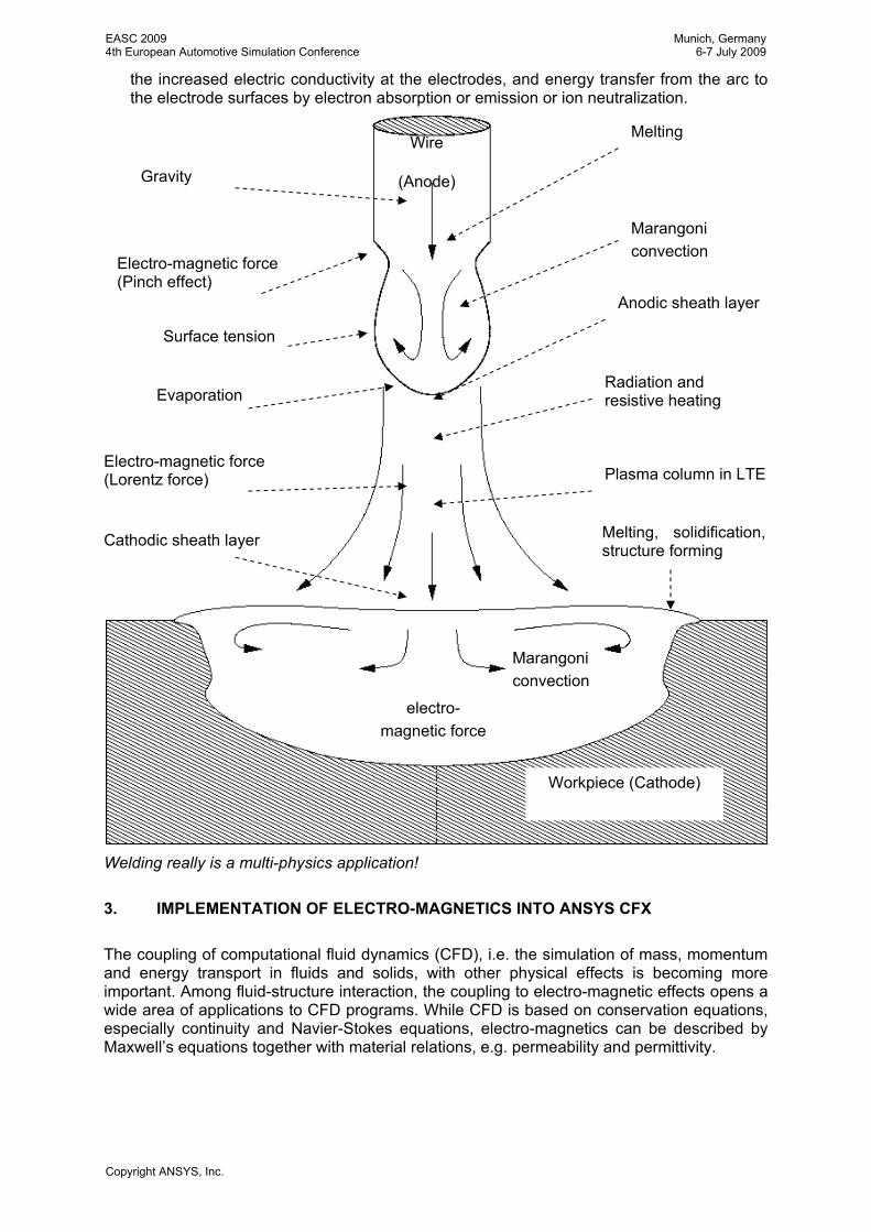
the increased electric conductivity at the electrodes, and energy transfer from the arc to the electrode surfaces by electron absorption or emission or ion neutralization.
Welding really is a multi-physics application!
3. IMPLEMENTATION OF ELECTRO-MAGNETICS INTO ANSYS CFX The coupling of computational fluid dynamics (CFD), i.e. the simulation of mass, momentum and energy transport in fluids and solids, with other physical effects is becoming more important. Among fluid-structure interaction, the coupling to electro-magnetic effects opens a wide area of applications to CFD programs. While CFD is based on conservation equations, especially continuity and Navier-Stokes equations, electro-magnetics can be described by Maxwell’s equations together with material relations, e.g. permeability and permittivity.
Wire
(Anode)
Marangoni convection
electro- magnetic force
Workpiece (Cathode)
Gravity
Electro-magnetic force (Pinch effect)
Surface tension
Evaporation
Electro-magnetic force (Lorentz force)
Melting
Marangoni convection
Anodic sheath layer
Radiation and resistive heating
Plasma column in LTE
Cathodic sheath layer Melting, solidification, structure forming
EASC 20094th European Automotive Simulation Conference
Munich, Germany6-7 July 2009
Copyright ANSYS, Inc.
Coupling of both areas can be done externally, i.e. by data transfer between separated programs specialized for CFD, e.g. ANSYS CFX, and electro-magnetics, e.g. ANSYS EMAG; or it can be done internally, i.e. all equations are solved in one solver. The main advantages of the latter approach are the strong internal coupling and the ease of use (single program, single mesh, single setup, no coupling interface). Since a direct implementation of Maxwell’s equations into a CFD solver is difficult and often needless complex, assumptions and simplifications lead to three separate areas of application of coupled CFD and electro-magnetics:
• Ferro-Hydrodynamics (FHD) : Magnetic dipoles are accelerated by Kelvin force in magnetic fields; electric effects are neglected; examples are ferrofluids for ink jet printers or separation of magnetic cells.
• Electro-Hydrodynamics (EHD) : Charged particles (electric monopoles or dipoles) are accelerated by Coulomb force in electric fields; magnetic effects are neglected; typical examples are electrophoresis, electroosmosis, fuel cells, electrolysis, electrostatic coating.
• Magneto-Hydrodynamics (MHD) : Electric conducting fluids or solids in electric and/or magnetic fields are accelerated by Lorentz force and heated by resistive heating; free electric charges or magnetic dipoles are neglected; examples are arc welding, plasma cutting, circuit breakers, heating, retarding and stirring of casts, and Hartmann flow of liquid metals.
4. MAGNETO-HYDRODYNAMICS FOR ELECTRIC ARCS In MHD, free electric charges and free magnetic dipoles are neglected. The fluids and solids can be described by their electrical conductivity (often strongly temperature dependent) and relative permeability. Electric current is generated by an applied external voltage and by fluid motion in the magnetic field (Ohm’s law). The electric current leads to resistive heating and generates a magnetic field; current and magnetic field cause a Lorentz force onto the fluid. The basic equations for electro-magnetics in quasi-stationary MHD for electric arcs are:
ABB
jA
j
rrr
rr
r
curl
grad0graddiv
0
0
+=
−=Δ
Φ−=
=Φ
μ
σ
σ
with electrical conductivity σ, electric potential Φ, current density j, magnetic vector potential A, magnetic permeability µ, and magnetic induction B. The interaction with the fluid flow is through Lorentz force
tDjH∂∂
+=r
rrcurl
0div =Br
tBE∂∂
−=r
rcurl
eD ρ=r
div0)div( =+∂∂ ut
rρρ
Kr
+∂∂
−=+∂
∂
ii
i
xpuu
tu )div()( ρρ
Basic CFD equations Maxwell’s equations
EASC 20094th European Automotive Simulation Conference
Munich, Germany6-7 July 2009
Copyright ANSYS, Inc.
Bjf Lrrr
×= and resistive heating
σ
2jSh =
In a typical MHD problem like arc welding, the following set of equations will be solved: • conservation of total mass and component masses, • conservation of momentum (Navier-Stokes) with Lorentz force, • conservation of energy with resistive heating, • equations for turbulence modelling (e.g. SST), • conservation of electric charge, and • equations for magnetic vector potential.
The complexity is increased by the strong temperature, pressure and concentration dependency of gas properties like density, viscosity, thermal and electrical conductivity and heat capacity. This system of non-linear partial differential equations is strongly coupled so that the solution inside one solver, here ANSYS CFX, leads to more robustness and better convergence than a coupled solution between different solvers. The stability and convergence of ANSYS CFX were excellent even with the strong temperature- and pressure-dependency of the material properties, even though the gradients for example in temperature at the electrodes were extremely high (20,000 K over less than 1 mm) and even though the physics being simulated is very complex and strongly coupled. This shows the advantage of an internally coupling approach between multi-physics. Coupling to external programs like ANSYS becomes necessary when stresses and distortion shall be calculated from temperature cycles and weld pool geometry coming form ANSYS CFX process simulation. Since strong distortion has an effect on welding process, a bi-directional coupling may be necessary.
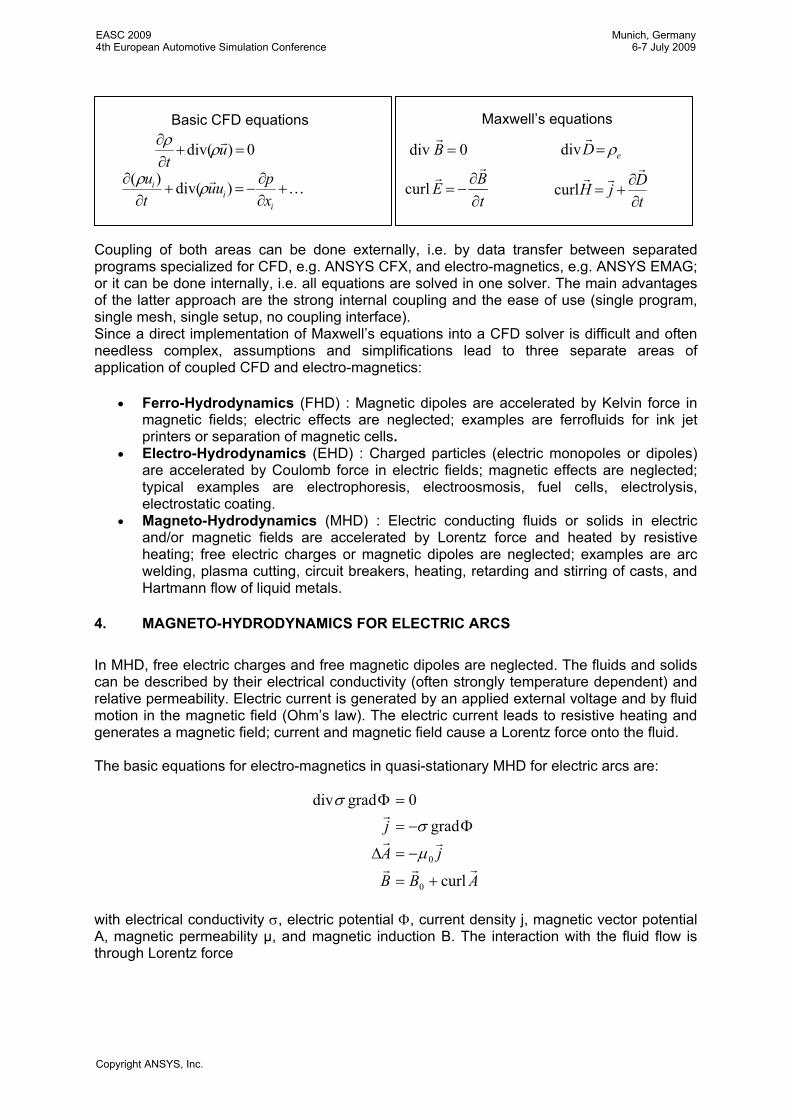
Left hand side: Electro-magnetic stirring of an acid, caused by an external magnetic field and an applied voltage between the cylindrical electrodes; vertical velocity by colors and a typical streamline. Middle and right hand side: Plasma-Gas Metal Arc welding with two arcs: between wire and work piece and between plasma electrode and work piece; picture at right shows temperature as colors.
EASC 20094th European Automotive Simulation Conference
Munich, Germany6-7 July 2009
Copyright ANSYS, Inc.
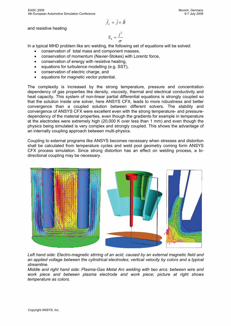
5. IMPLEMENTATION OF ARC PHYSICS Arc column is typically assumed in local thermodynamic equilibrium (LTE) so that the gas properties can be pre-computed as functions of temperature and pressure. [2] Gas mixtures are implemented as multi-component fluid, mixture properties are calculated with mass fraction weighting or user specified, e.g. viscosity and thermal conductivity from mixture law of Wassiljewa.
EASC 20094th European Automotive Simulation Conference
Munich, Germany6-7 July 2009
Copyright ANSYS, Inc.
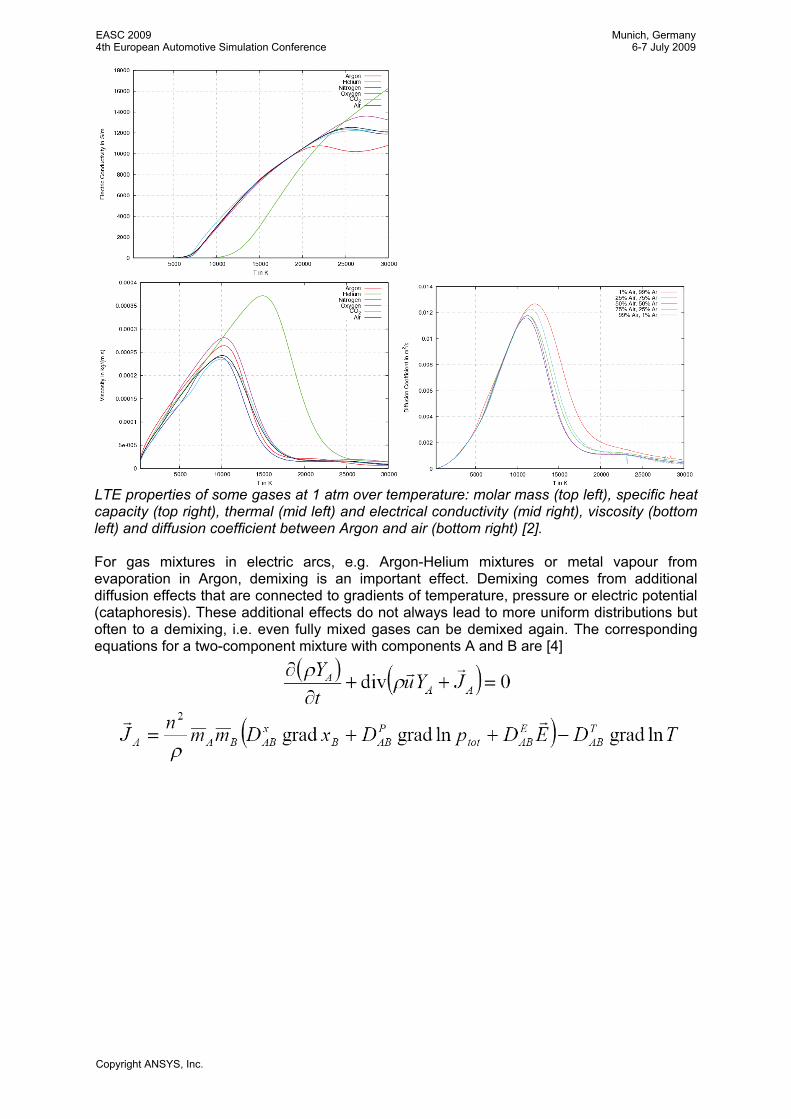
LTE properties of some gases at 1 atm over temperature: molar mass (top left), specific heat capacity (top right), thermal (mid left) and electrical conductivity (mid right), viscosity (bottom left) and diffusion coefficient between Argon and air (bottom right) [2]. For gas mixtures in electric arcs, e.g. Argon-Helium mixtures or metal vapour from evaporation in Argon, demixing is an important effect. Demixing comes from additional diffusion effects that are connected to gradients of temperature, pressure or electric potential (cataphoresis). These additional effects do not always lead to more uniform distributions but often to a demixing, i.e. even fully mixed gases can be demixed again. The corresponding equations for a two-component mixture with components A and B are [4]
EASC 20094th European Automotive Simulation Conference
Munich, Germany6-7 July 2009
Copyright ANSYS, Inc.
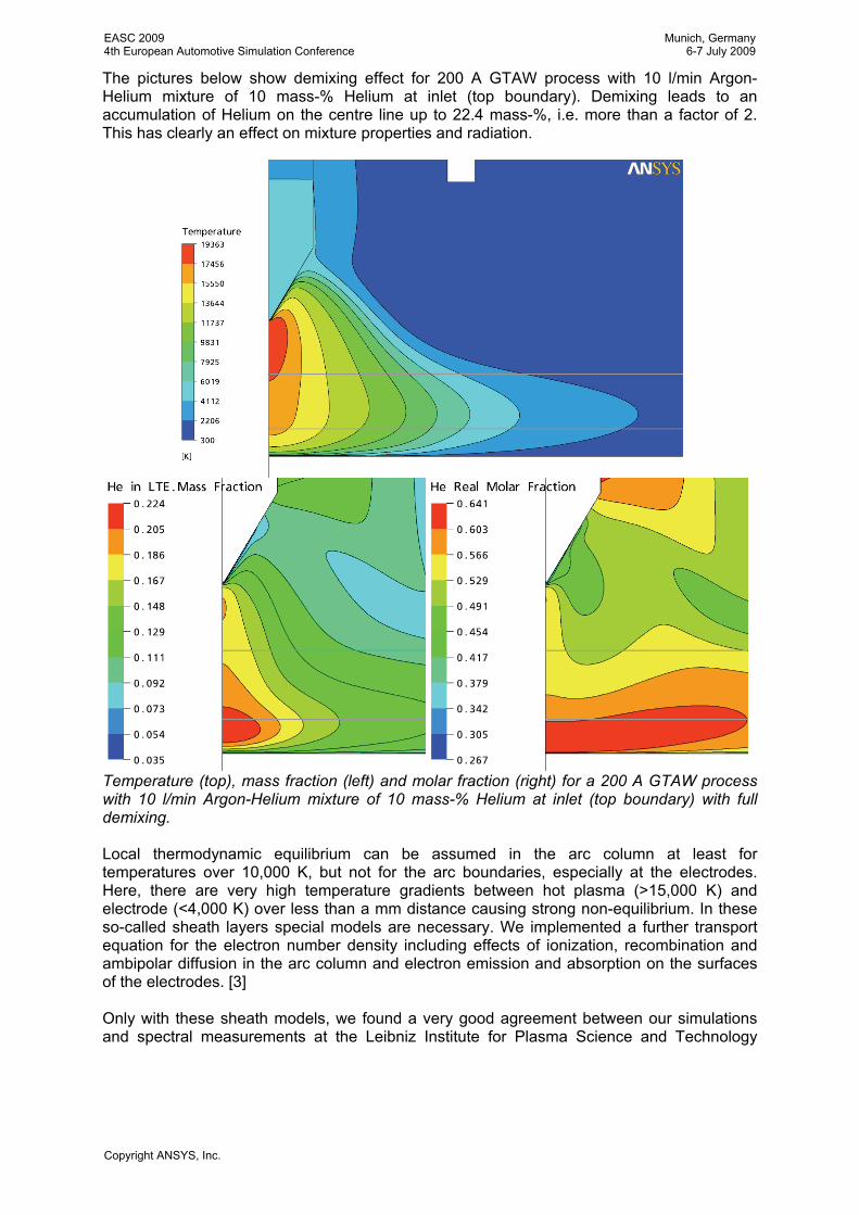
The pictures below show demixing effect for 200 A GTAW process with 10 l/min Argon-Helium mixture of 10 mass-% Helium at inlet (top boundary). Demixing leads to an accumulation of Helium on the centre line up to 22.4 mass-%, i.e. more than a factor of 2. This has clearly an effect on mixture properties and radiation.
Temperature (top), mass fraction (left) and molar fraction (right) for a 200 A GTAW process with 10 l/min Argon-Helium mixture of 10 mass-% Helium at inlet (top boundary) with full demixing. Local thermodynamic equilibrium can be assumed in the arc column at least for temperatures over 10,000 K, but not for the arc boundaries, especially at the electrodes. Here, there are very high temperature gradients between hot plasma (>15,000 K) and electrode (<4,000 K) over less than a mm distance causing strong non-equilibrium. In these so-called sheath layers special models are necessary. We implemented a further transport equation for the electron number density including effects of ionization, recombination and ambipolar diffusion in the arc column and electron emission and absorption on the surfaces of the electrodes. [3] Only with these sheath models, we found a very good agreement between our simulations and spectral measurements at the Leibniz Institute for Plasma Science and Technology
EASC 20094th European Automotive Simulation Conference
Munich, Germany6-7 July 2009
Copyright ANSYS, Inc.
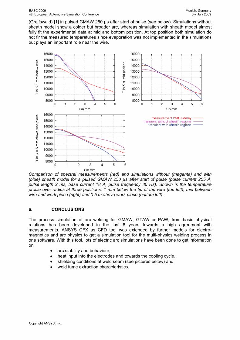
(Greifswald) [1] in pulsed GMAW 250 µs after start of pulse (see below). Simulations without sheath model show a colder but broader arc, whereas simulation with sheath model almost fully fit the experimental data at mid and bottom position. At top position both simulation do not fir the measured temperatures since evaporation was not implemented in the simulations but plays an important role near the wire.
Comparison of spectral measurements (red) and simulations without (magenta) and with (blue) sheath model for a pulsed GMAW 250 µs after start of pulse (pulse current 255 A, pulse length 2 ms, base current 18 A, pulse frequency 30 Hz). Shown is the temperature profile over radius at three positions: 1 mm below the tip of the wire (top left), mid between wire and work piece (right) and 0.5 m above work piece (bottom left).
6. CONCLUSIONS The process simulation of arc welding for GMAW, GTAW or PAW, from basic physical relations has been developed in the last 8 years towards a high agreement with measurements. ANSYS CFX as CFD tool was extended by further models for electro-magnetics and arc physics to get a simulation tool for the multi-physics welding process in one software. With this tool, lots of electric arc simulations have been done to get information on
• arc stability and behaviour, • heat input into the electrodes and towards the cooling cycle, • shielding conditions at weld seam (see pictures below) and • weld fume extraction characteristics.
EASC 20094th European Automotive Simulation Conference
Munich, Germany6-7 July 2009
Copyright ANSYS, Inc.
SeveraldevelopAiF/DFG[6].
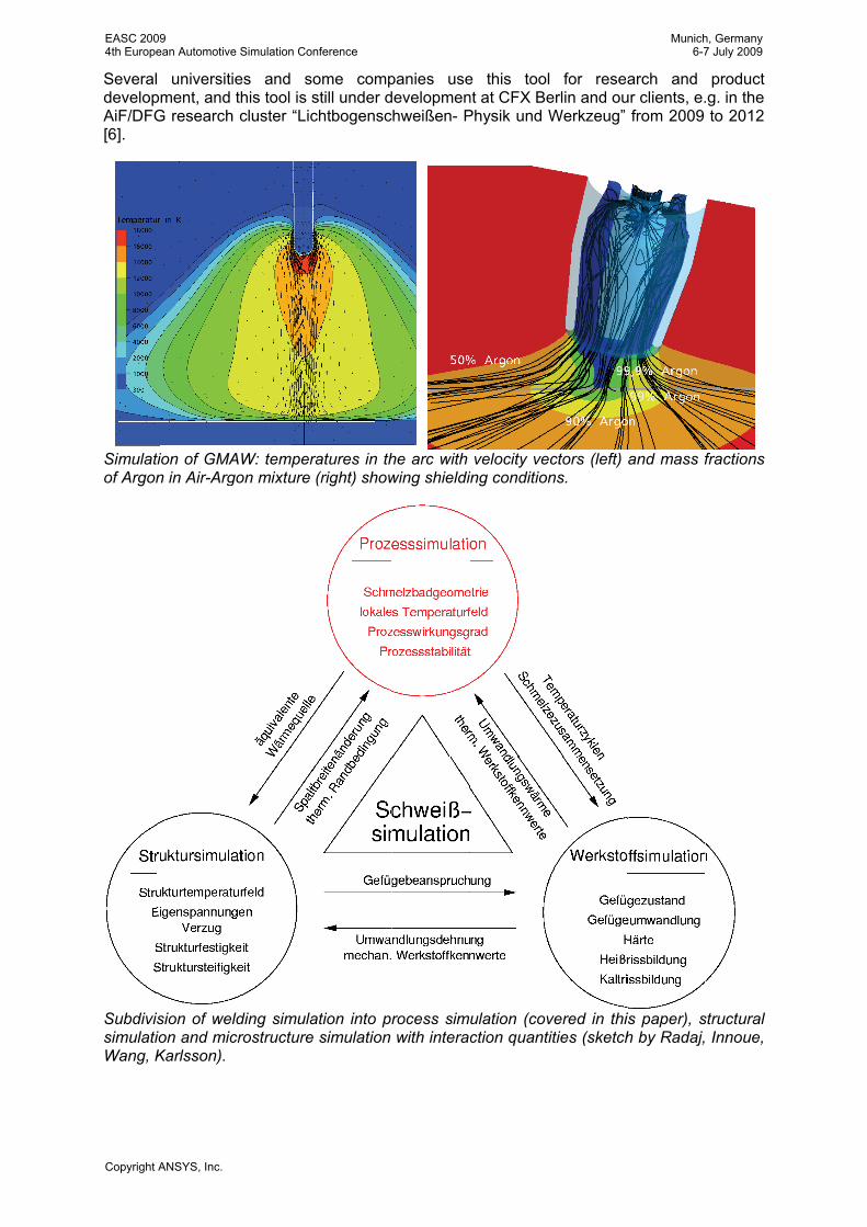
Simulatof Argon
SubdivissimulatiWang, K
universitiepment, and G research
tion of GMAn in Air-Arg
ision of welion and micKarlsson).
es and sothis tool is scluster “Lic
AW: tempergon mixture
lding simulacrostructure
ome compstill under dchtbogensc
ratures in th(right) show
ation into pr simulation
panies usedevelopmenhweißen- P
he arc with wing shieldi
rocess simwith interac
e this toolnt at CFX BePhysik und W
velocity veing condition
ulation (covction quanti
l for reseerlin and ouWerkzeug”
ectors (left) ns.
vered in thitities (sketch
arch and ur clients, e.
from 2009
and mass f
is paper), sh by Radaj,
product .g. in the to 2012
fractions
structural Innoue,
EASC 20094th European Automotive Simulation Conference
Munich, Germany6-7 July 2009
Copyright ANSYS, Inc.
But process simulation is only a part of full welding simulation: structural simulation to calculate stress and deformation and microstructure simulation to calculate metal structure after welding and formation of cracks have to interact by several quantities to get a consistent simulation of the overall welding process. So far, each part is used uncoupled and interacts only by hand, e.g. by extracting equivalent heat sources from process simulation to structural simulation and the deformation back. Combining the different tools ANSYS CFX for process simulation and Virtual Weld Shop (VWS) based on ANSYS for structural and microstructure simulation offers the possibility to get a tool for welding simulation.
7. LITERATURE [1] ChopArc: MSG-Lichtbogenschweißen für den Ultraleichtbau, S.-F. Goecke, E. Metzke, A.
Spille-Kohoff, M.Langula, Fraunhofer IRB Verlag 2005, ISBN 3-8167-6766-4. [2] Transport Coefficients of Argon, Nitrogen, Oxygen, Argon-Nitrogen, and Argon-Oxygen
Plasmas, A:B: Murphy, C.J. Arundell, Plasma Chemistry and Plasma Processing 14 (1994), Nr. 4.
[3] Prediction of properties of free burning arcs including effects of ambipolar diffusion, L. Sansonnens, J. Haidar, J.J. Lowke, Journal of Physics D: Applied Physics 33 (2000), Nr. 2.
[4] Thermal plasmas in gas mixtures, A B Murphy, J. Phys. D: Appl. Phys. 34 (2001), R151-R173
[5] Numerical Investigations of the Influence of Metal Vapour in GMA Welding, M. Schnick, M. Häßler, U. Füssel, M. Hertel; A. Spille-Kohoff, A. B. Murphy, Dresdner Fügetechnisches Kolloquium 2009
[6] http://www.dvs-ev.de/fv/forschungsverbuende/4.pdf
EASC 20094th European Automotive Simulation Conference
Munich, Germany6-7 July 2009
Copyright ANSYS, Inc.


![Synergies between Imaging and Spectroscopic SurveysLensing of CMASS Rx Σ ΔΣ od Σ meas R [Mpc/h] R [Mpc/h] ΔΣ od / ΔΣ meas Standard galaxy-halo models constrained by clustering](https://static.fdocument.org/doc/165x107/5e74abc84c9dde5b49526ffd/synergies-between-imaging-and-spectroscopic-surveys-lensing-of-cmass-rx-.jpg)