APPLIED SYSTEMS - ΚΛΙΜΑΜΗΧΑΝΙΚΗ - DAIKIN … · 2017-05-05 · 239 applied systems...
127
Transcript of APPLIED SYSTEMS - ΚΛΙΜΑΜΗΧΑΝΙΚΗ - DAIKIN … · 2017-05-05 · 239 applied systems...

GC_pre2_lowres.pdf 238 30/11/2011 12:31:40
239
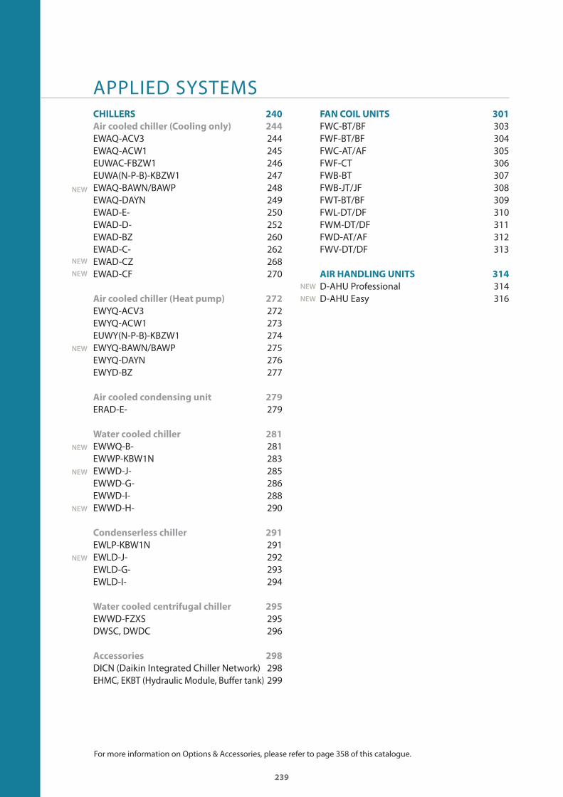
APPLIED SYSTEMSCHILLERS 240
Air cooled chiller (Cooling only) 244
EWAQ-ACV3 244EWAQ-ACW1 245EUWAC-FBZW1 246EUWA(N-P-B)-KBZW1 247EWAQ-BAWN/BAWP 248EWAQ-DAYN 249EWAD-E- 250EWAD-D- 252EWAD-BZ 260EWAD-C- 262EWAD-CZ 268EWAD-CF 270
Air cooled chiller (Heat pump) 272
EWYQ-ACV3 272EWYQ-ACW1 273EUWY(N-P-B)-KBZW1 274EWYQ-BAWN/BAWP 275EWYQ-DAYN 276EWYD-BZ 277
Air cooled condensing unit 279
ERAD-E- 279
Water cooled chiller 281
EWWQ-B- 281EWWP-KBW1N 283EWWD-J- 285EWWD-G- 286EWWD-I- 288EWWD-H- 290
Condenserless chiller 291
EWLP-KBW1N 291EWLD-J- 292EWLD-G- 293EWLD-I- 294
Water cooled centrifugal chiller 295
EWWD-FZXS 295DWSC, DWDC 296
Accessories 298
DICN (Daikin Integrated Chiller Network) 298EHMC, EKBT (Hydraulic Module, Buff er tank) 299
FAN COIL UNITS 301
FWC-BT/BF 303FWF-BT/BF 304FWC-AT/AF 305FWF-CT 306FWB-BT 307FWB-JT/JF 308FWT-BT/BF 309FWL-DT/DF 310FWM-DT/DF 311FWD-AT/AF 312FWV-DT/DF 313
AIR HANDLING UNITS 314
D-AHU Professional 314D-AHU Easy 316
NEW
NEW
NEW
NEW
NEW
NEW
NEW
NEW
NEW
NEW
For more information on Options & Accessories, please refer to page 358 of this catalogue.
GC_pre2_lowres.pdf 239 30/11/2011 12:31:41
240
��������
Refrigeran
t
Inverter
Free
coo
ling Compressor Effi ciency version Sound version
Swing
Scro
ll
Screw
Cen
trifu
gal
Stan
dard
High
Prem
ium
High am
bient
Stan
dard
Low
Redu
ced
Extra
low
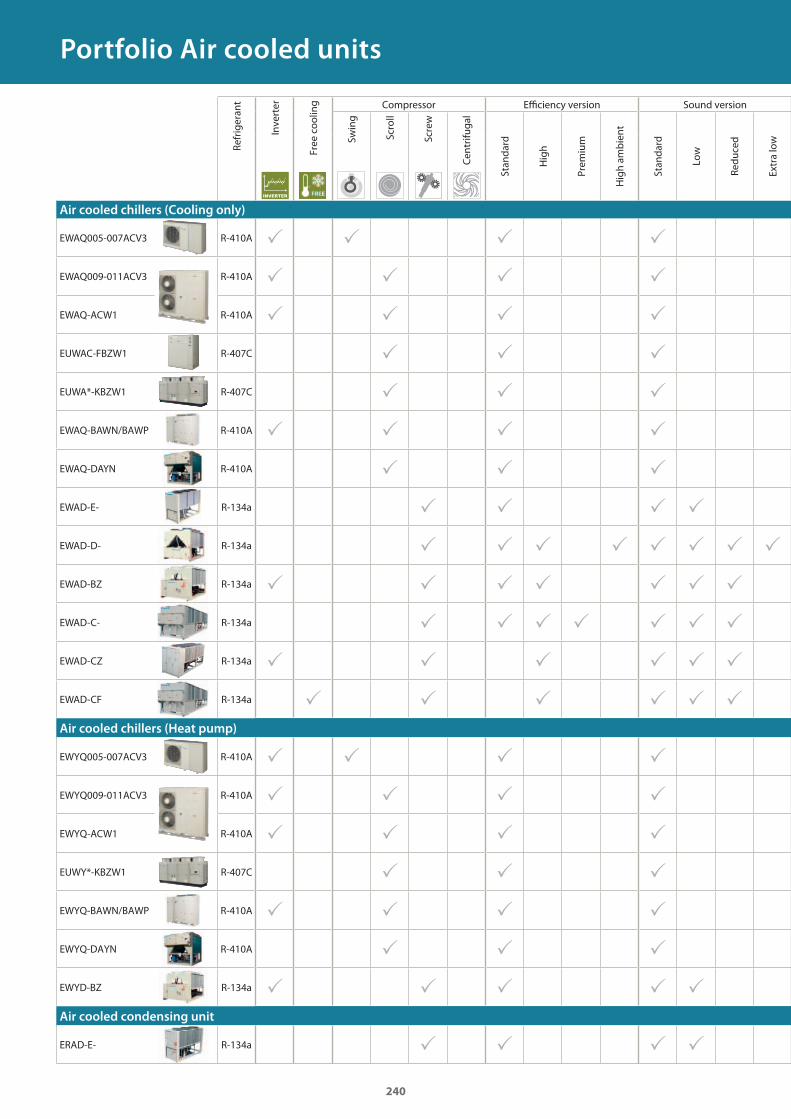
Air cooled chillers (Cooling only)
EWAQ005-007ACV3 R-410A � � � �
EWAQ009-011ACV3 R-410A � � � �
EWAQ-ACW1 R-410A � � � �
EUWAC-FBZW1 R-407C � � �
EUWA*-KBZW1 R-407C � � �
EWAQ-BAWN/BAWP R-410A � � � �
EWAQ-DAYN R-410A � � �
EWAD-E- R-134a � � � �
EWAD-D- R-134a � � � � � � � �
EWAD-BZ R-134a � � � � � � �
EWAD-C- R-134a � � � � � � �
EWAD-CZ R-134a � � � � � �
EWAD-CF R-134a � � � � � �Air cooled chillers (Heat pump)
EWYQ005-007ACV3 R-410A � � � �
EWYQ009-011ACV3 R-410A � � � �
EWYQ-ACW1 R-410A � � � �
EUWY*-KBZW1 R-407C � � �
EWYQ-BAWN/BAWP R-410A � � � �
EWYQ-DAYN R-410A � � �
EWYD-BZ R-134a � � � � �Air cooled condensing unit
ERAD-E- R-134a � � � �
General chiller overviewPortfolio Air cooled units
GC_pre2_lowres.pdf 240 30/11/2011 12:31:41
241241
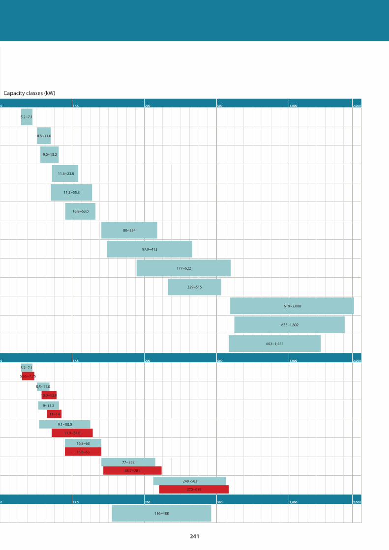
Capacity classes (kW)
0 17.5 200 500 1,000 2,000
0 17.5 200 500 1,000 2,000
0 17.5 200 500 1,000 2,000
5.2~7.1
5.2~7.1
8.5~11.0
8.5~11.0
9~13.2
9.0~13.2
11.6~23.8
11.3~55.3
9.1~50.0
16.8~63.0
16.8~63
80~254
77~252
97.9~413
177~622
329~515
116~488
248~583
619~2,008
635~1,802
602~1,555
270~615
88.7~281
16.8~63
11.9~54.0
11~14
10.0~13.0
5.65~7.75
GC_pre2_lowres.pdf 241 30/11/2011 16:04:45
242
��������
Refrigeran
t
Inverter
Free
coo
ling Compressor Effi ciency version Sound version
Swing
Scro
ll
Screw
Cen
trifu
gal
Stan
dard
High
Prem
ium
High am
bient
Stan
dard
Low
Redu
ced
Extra
low
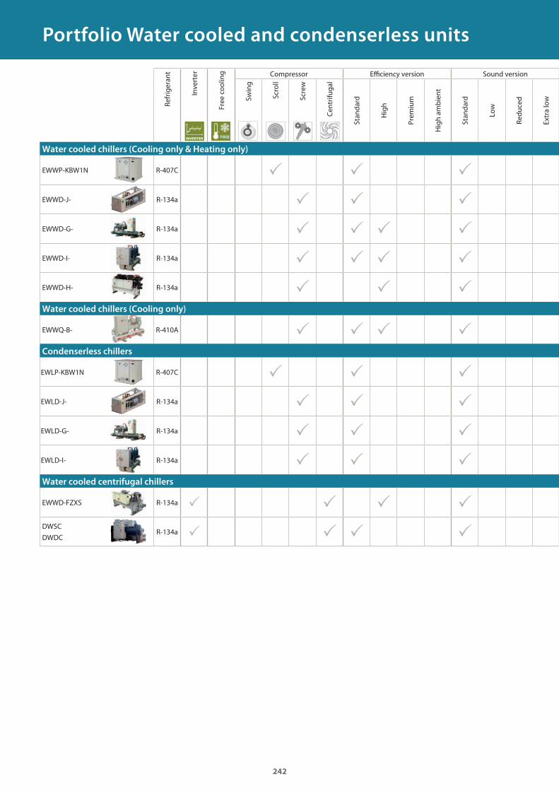
Water cooled chillers (Cooling only & Heating only)
EWWP-KBW1N R-407C � � �
EWWD-J- R-134a � � �
EWWD-G- R-134a � � � �
EWWD-I- R-134a � � � �
EWWD-H- R-134a � � �Water cooled chillers (Cooling only)
EWWQ-B- R-410A � � � �Condenserless chillers
EWLP-KBW1N R-407C � � �
EWLD-J- R-134a � � �
EWLD-G- R-134a � � �
EWLD-I- R-134a � � �Water cooled centrifugal chillers
EWWD-FZXS R-134a � � � �DWSC
DWDCR-134a � � � �
Portfolio Water cooled and condenserless units
GC_pre2_lowres.pdf 242 30/11/2011 12:31:42
243243
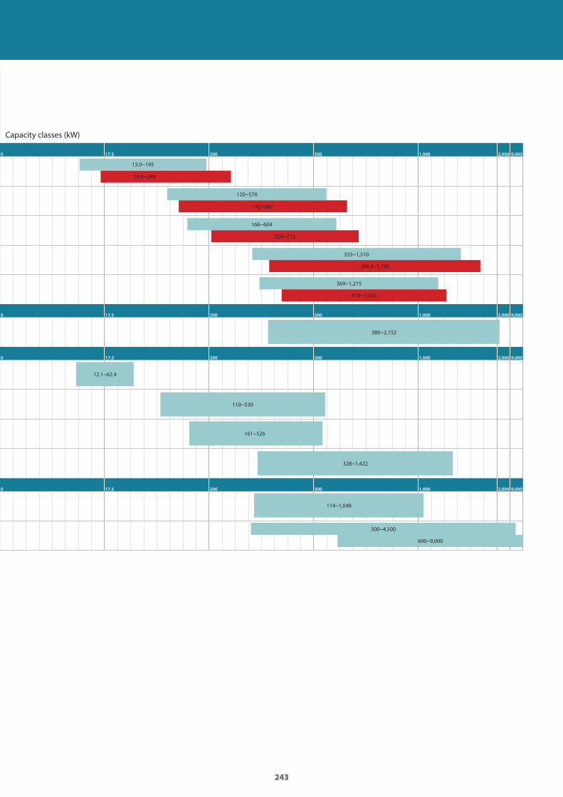
Capacity classes (kW)
0 17.5 200 500 1,000 2,000 9,000
0 17.5 200 500 1,000 2,000 9,000
0 17.5 200 500 1,000 2,000 9,000
0 17.5 200 500 1,000 2,000 9,000
13.0~195
120~570
166~604
333~1,510
369~1,215
300~4,500
16.6~248
142~681
204~712
388.4~1,790
419~1,356
600~9,000
380~2,152
12.1~62.4
110~530
161~526
328~1,422
114~1,048
GC_pre2_lowres.pdf 243 30/11/2011 12:31:42
244
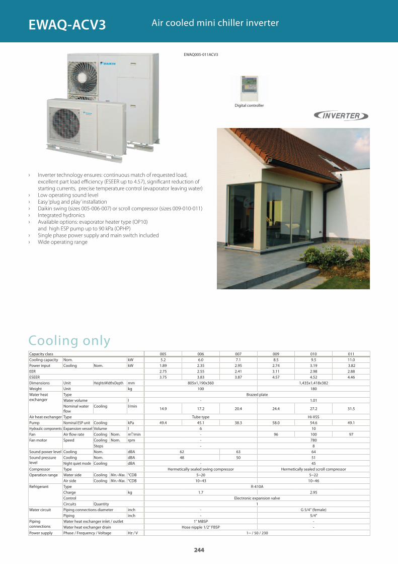
Air cooled mini chiller inverter
› Inverter technology ensures: continuous match of requested load,
excellent part load efficiency (ESEER up to 4.57), significant reduction of
starting currents, precise temperature control (evaporator leaving water)
› Low operating sound level
› Easy ‘plug and play’ installation
› Daikin swing (sizes 005-006-007) or scroll compressor (sizes 009-010-011)
› Integrated hydronics
› Available options: evaporator heater type (OP10)
and high ESP pump up to 90 kPa (OPHP)
› Single phase power supply and main switch included
› Wide operating range
Cooling onlyCapacity class 005 006 007 009 010 011Cooling capacity Nom. kWPower input Cooling Nom. kWEERESEERDimensions Unit HeightxWidthxDepth mmWeight Unit kgWater heat exchanger
Type Brazed plateWater volume lNominal water flow
Cooling l/min
Air heat exchanger Type Tube type Hi-XSSPump Nominal ESP unit Cooling kPaHydraulic components Expansion vessel Volume lFan Air flow rate Cooling Nom. m³/minFan motor Speed Cooling Nom. rpm
StepsSound power level Cooling Nom. dBASound pressure level
Cooling Nom. dBANight quiet mode Cooling dBA
Compressor Type Hermetically sealed swing compressor Hermetically sealed scroll compressorOperation range Water side Cooling Min.~Max. °CDB
Air side Cooling Min.~Max. °CDBRefrigerant Type R-410A
Charge kgControl Electronic expansion valveCircuits Quantity
Water circuit Piping connections diameter inch G 5/4" (female)Piping inch
Piping connections
Water heat exchanger inlet / outletWater heat exchanger drain Hose nipple 1/2" FBSP
Power supply Phase / Frequency / Voltage Hz / V
Digital controller
244
5.2 6.0 7.1 8.5 9.5 11.0
1.89 2.35 2.95 2.74 3.19 3.82 2.75 2.55 2.41 3.11 2.98 2.88 3.75 3.83 3.87 4.57 4.52 4.46
805x1,190x360 1,435x1,418x382100 180
- 1.01
14.9 17.2 20.4 24.4 27.2 31.5
49.4 45.1 38.3 58.0 54.6 49.16 10- 96 100 97- 780- 8
62 63 6448 50 51
- 45
5~20 5~2210~43 10~46
1.7 2.95
1-- 5/4"
1" MBSP --
1~ / 50 / 230
244
EWAQ-ACV3
EWAQ005-011ACV3
GC_pre2_lowres.pdf 244 30/11/2011 12:31:42
245
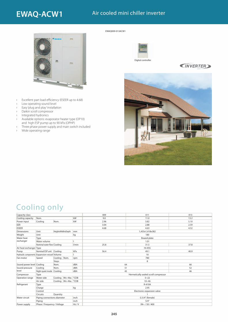
Cooling onlyCapacity class 009 011 013Cooling capacity Nom. kWPower input Cooling Nom. kWEERESEERDimensions Unit HeightxWidthxDepth mmWeight Unit kgWater heat exchanger
Type Brazed plateWater volume lNominal water flow Cooling l/min
Air heat exchanger Type Hi-XSSPump Nominal ESP unit Cooling kPaHydraulic components Expansion vessel Volume lFan motor Speed Cooling Nom. rpm
StepsSound power level Cooling Nom. dBASound pressure level
Cooling Nom. dBANight quiet mode Cooling dBA
Compressor Type Hermetically sealed scroll compressorOperation range Water side Cooling Min.~Max. °CDB
Air side Cooling Min.~Max. °CDBRefrigerant Type R-410A
Charge kgControl Electronic expansion valveCircuits Quantity
Water circuit Piping connections diameter inch G 5/4" (female)Piping inch
Power supply Phase / Frequency / Voltage Hz / V
Air cooled mini chiller inverter
› Excellent part load efficiency (ESEER up to 4.68)
› Low operating sound level
› Easy ‘plug and play’ installation
› Daikin scroll compressor
› Integrated hydronics
› Available options: evaporator heater type (OP10)
and high ESP pump up to 90 kPa (OPHP)
› Three phase power supply and main switch included
› Wide operating range
Digital controller
245
9.0 11.0 13.22.96 3.82 5.10 3.04 2.88 2.59 4.68 4.63 4.52
1,435x1,418x382180
1.0125.8 31.5 37.8
56.4 49.1 40.9107808
64 6651 5245 46
5~2210~46
2.95
1
5/4"3N~ / 50 / 400
245
EWAQ-ACW1
EWAQ009-013ACW1
GC_pre2_lowres.pdf 245 30/11/2011 12:31:42
246
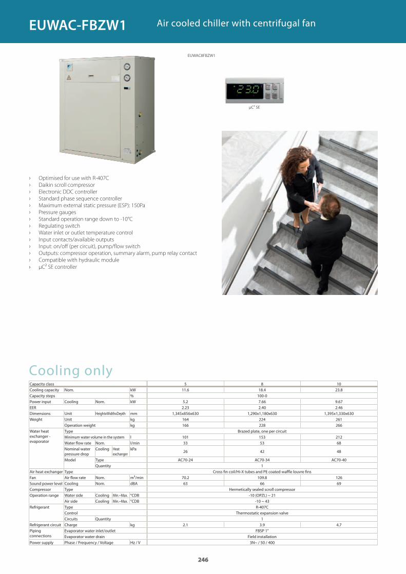
Cooling onlyCapacity class 5 8 10Cooling capacity Nom. kWCapacity steps %Power input Cooling Nom. kWEERDimensions Unit HeightxWidthxDepth mmWeight Unit kg
Operation weight kgWater heat exchanger - evaporator
Type Brazed plate, one per circuitMinimum water volume in the system lWater flow rate Nom. l/minNominal water pressure drop
Cooling Heat exchanger
kPa
Model Type AC70-24 AC70-34 AC70-40Quantity
Air heat exchanger Type Cross fin coil/Hi-X tubes and PE coated waffle louvre finsFan Air flow rate Nom. m³/minSound power level Cooling Nom. dBACompressor Type Hermetically sealed scroll compressorOperation range Water side Cooling Min.~Max. °CDB
Air side Cooling Min.~Max. °CDBRefrigerant Type R-407C
Control Thermostatic expansion valveCircuits Quantity
Refrigerant circuit Charge kgPiping connections
Evaporator water inlet/outlet FBSP 1"Evaporator water drain Field installation
Power supply Phase / Frequency / Voltage Hz / V
› Optimised for use with R-407C
› Daikin scroll compressor
› Electronic DDC controller
› Standard phase sequence controller
› Maximum external static pressure (ESP): 150Pa
› Pressure gauges
› Standard operation range down to -10°C
› Regulating switch
› Water inlet or outlet temperature control
› Input contacts/available outputs
› Input: on/off (per circuit), pump/flow switch
› Outputs: compressor operation, summary alarm, pump relay contact
› Compatible with hydraulic module
› μC² SE controller
Air cooled chiller with centrifugal fan
246
11.6 18.4 23.8100-0
5.2 7.66 9.672.23 2.40 2.46
1,345x856x630 1,290x1,180x630 1,395x1,330x630164 224 261166 228 266
101 153 21233 53 68
26 42 48
1
70.2 109.8 12663 66 69
-10 (OPZL) ~ 21-10 ~ 43
12.1 3.9 4.7
3N~ / 50 / 400
246
EUWAC8FBZW1
EUWAC-FBZW1
μC² SE
GC_pre2_lowres.pdf 246 30/11/2011 12:31:43
247
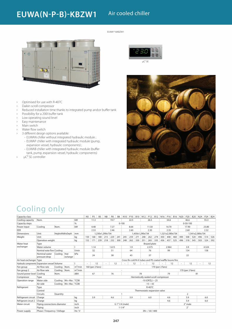
Cooling onlyCapacity class N5 P5 B5 N8 P8 B8 N10 P10 B10 N12 P12 B12 N16 P16 B16 N20 P20 B20 N24 P24 B24Cooling capacity Nom. kWCapacity steps %Power input Cooling Nom. kWEERDimensions Unit HeightxWidthxDepth mmWeight Unit kg
Operation weight kgWater heat exchanger
Type Brazed plateWater volume lNominal water flow Cooling l/minNominal water pressure drop
Cooling Heat exchanger
kPa
Air heat exchanger Type Cross fin coil/Hi-X tubes and PE coated waffle louvre finsHydraulic components Expansion vessel Volume lFan group Air flow rate Cooling Nom. m³/min 160 (per 2 fans) 170 (per 2 fans)Fan group 2 Air flow rate Cooling Nom. m³/min - 170 (per 2 fans)Sound power level Cooling Nom. dBACompressor Type Hermetically sealed scroll compressorOperation range Water side Cooling Min.~Max. °CDB
Air side Cooling Min.~Max. °CDBRefrigerant Type R-407C
Control Thermostatic expansion valveCircuits Quantity
Refrigerant circuit Charge kgRefrigerant circuit 2 Charge kgWater circuit Piping connections diameter inch G 1"1/4 (male)
Piping inchPower supply Phase / Frequency / Voltage Hz / V
› Optimised for use with R-407C
› Daikin scroll compressor
› Reduced installation time thanks to integrated pump and;or buffer tank
› Possibility for a 200l buffer tank
› Low operating sound level
› Easy maintenance
› Main switch
› Water flow switch
› 3 different design options available:
- EUWAN chiller without integrated hydraulic module ;
- EUWAP chiller with integrated hydraulic module (pump,
expansion vessel, hydraulic components) ;
- EUWAB chiller with integrated hydraulic module (buffer
tank, pump, expansion vessel, hydraulic components)
› μC² SE controller
Air cooled chiller
247
11.3 19.7 22.5 26.5 34.6 46.6 55.3 0-100 0-50-100
4.48 7.27 8.64 11.50 14.70 17.90 23.802.53 2.46 2.60 2.30 2.35 2.60 2.32
1,230x1,290x734 1,450x1,290x734 1,321x2,580x734 1,541x2,580x734150 168 180 215 229 241 245 259 271 248 262 274 430 448 460 490 508 520 496 514 526152 171 239 218 232 300 248 262 330 251 265 335 436 457 525 496 518 545 503 524 592
1.14 1.615 1.9 2.375 2.964 3.9 4.52432 51 64 76 99 134 158
24 38 43 37 22
- 12 - 12 - 12 - 12 - 12 - 12 - 12
67 76 78 79 81
-10 (OPZL) ~ 25-15 ~ 43
1 23.9 4.6 5.9 6.0 4.6 5.9 6.0
- 4.6 5.9 6.02" male
1-1/4" 2"3N~ / 50 / 400
247
EUWA*16KBZW1
EUWA(N-P-B)-KBZW1
μC² SE
GC_pre2_lowres.pdf 247 30/11/2011 12:31:43
248
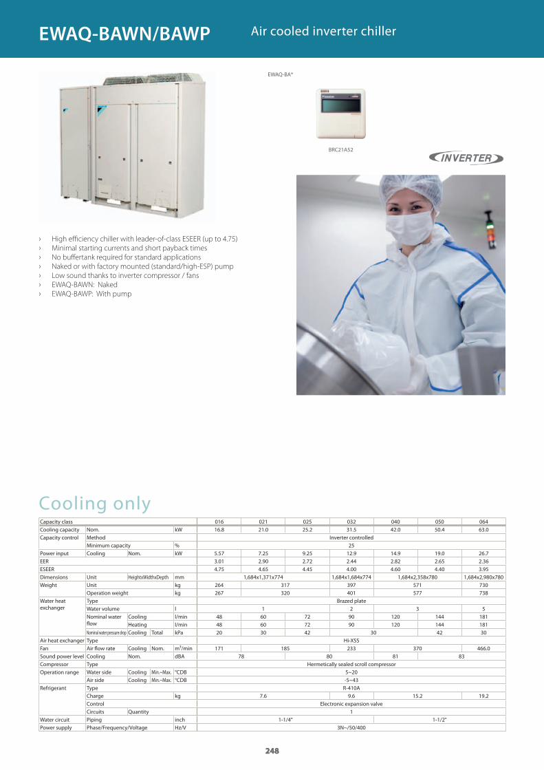
Cooling onlyCapacity classCooling capacity Nom. kWCapacity control Method Inverter controlled
Minimum capacity %Power input Cooling Nom. kWEERESEERDimensions Unit HeightxWidthxDepth mmWeight Unit kg
Operation weight kgWater heat exchanger
Type Brazed plateWater volume lNominal water flow
Cooling l/minHeating l/min
Nominal water pressure drop Cooling Total kPaAir heat exchanger Type Hi-XSSFan Air flow rate Cooling Nom. m³/minSound power level Cooling Nom. dBACompressor Type Hermetically sealed scroll compressorOperation range Water side Cooling Min.~Max. °CDB
Air side Cooling Min.~Max. °CDBRefrigerant Type R-410A
Charge kgControl Electronic expansion valveCircuits Quantity
Water circuit Piping inchPower supply Phase/Frequency/Voltage Hz/V
› High efficiency chiller with leader-of-class ESEER (up to 4.75)
› Minimal starting currents and short payback times
› No buffertank required for standard applications
› Naked or with factory mounted (standard/high-ESP) pump
› Low sound thanks to inverter compressor / fans
› EWAQ-BAWN: Naked
› EWAQ-BAWP: With pump
Air cooled inverter chiller
248
016 021 025 032 040 050 06416.8 21.0 25.2 31.5 42.0 50.4 63.0
255.57 7.25 9.25 12.9 14.9 19.0 26.73.01 2.90 2.72 2.44 2.82 2.65 2.364.75 4.65 4.45 4.00 4.60 4.40 3.95
1,684x1,371x774 1,684x1,684x774 1,684x2,358x780 1,684x2,980x780264 317 397 571 730267 320 401 577 738
1 2 3 548 60 72 90 120 144 18148 60 72 90 120 144 18120 30 42 30 42 30
171 185 233 370 466.078 80 81 83
5~20-5~43
7.6 9.6 15.2 19.2
11-1/4” 1-1/2"
3N~/50/400
248
EWAQ-BA*
BRC21A52
EWAQ-BAWN/BAWP
GC_pre2_lowres.pdf 248 30/11/2011 12:31:43
249
Cooling onlyCapacity class 080 100 130 150 180 210 240 260Cooling capacity Nom. kWCapacity steps %
Power input Cooling Nom. kWEERESEERDimensions Unit HeightxWidthxDepth mmWeight Unit kg
Operation weight kgWater heat exchanger
Type Brazed plateNominal water flow Cooling l/minNominal water pressure drop
Cooling Total kPa
Air heat exchanger Type Cross fin coil/Hi-Xss tubes and poly ethylene coated waffle finsFan Air flow rate Nom. m³/min
Speed rpmSound power level Cooling Nom. dBACompressor Type Scroll compressorOperation range Water side Cooling Min.~Max. °CDB
Air side Cooling Min.~Max. °CDBRefrigerant Type R-410A
Charge kgControl Electronic expansion valveCircuits Quantity
Piping connections
Water heat exchanger inlet / outletWater heat exchanger drain
Power supply Phase / Frequency / Voltage Hz / V
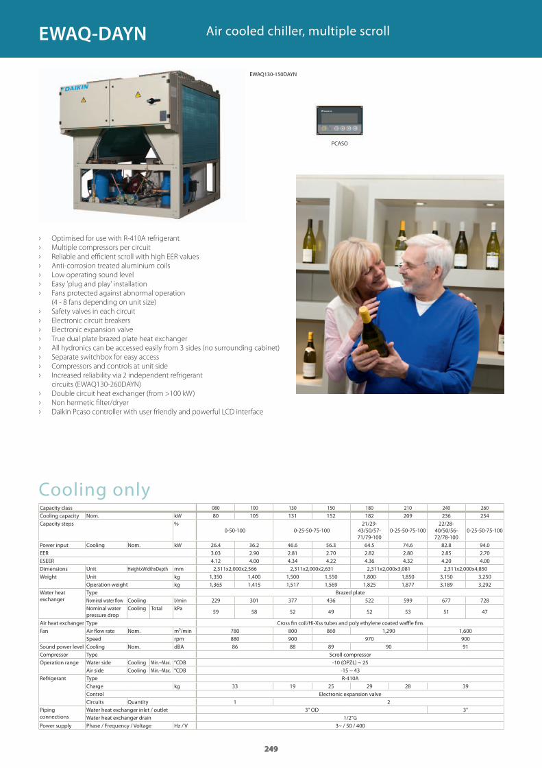
Air cooled chiller, multiple scroll
› Optimised for use with R-410A refrigerant
› Multiple compressors per circuit
› Reliable and efficient scroll with high EER values
› Anti-corrosion treated aluminium coils
› Low operating sound level
› Easy 'plug and play' installation
› Fans protected against abnormal operation
(4 - 8 fans depending on unit size)
› Safety valves in each circuit
› Electronic circuit breakers
› Electronic expansion valve
› True dual plate brazed plate heat exchanger
› All hydronics can be accessed easily from 3 sides (no surrounding cabinet)
› Separate switchbox for easy access
› Compressors and controls at unit side
› Increased reliability via 2 independent refrigerant
circuits (EWAQ130-260DAYN)
› Double circuit heat exchanger (from >100 kW)
› Non hermetic filter/dryer
› Daikin Pcaso controller with user friendly and powerful LCD interface
249
80 105 131 152 182 209 236 254
0-50-100 0-25-50-75-10021/29-
43/50/57-71/79-100
0-25-50-75-10022/28-
40/50/56-72/78-100
0-25-50-75-100
26.4 36.2 46.6 56.3 64.5 74.6 82.8 94.03.03 2.90 2.81 2.70 2.82 2.80 2.85 2.704.12 4.00 4.34 4.22 4.36 4.32 4.20 4.002,311x2,000x2,566 2,311x2,000x2,631 2,311x2,000x3,081 2,311x2,000x4,850
1,350 1,400 1,500 1,550 1,800 1,850 3,150 3,2501,365 1,415 1,517 1,569 1,825 1,877 3,189 3,292
229 301 377 436 522 599 677 728
59 58 52 49 52 53 51 47
780 800 860 1,290 1,600880 900 970 90086 88 89 90 91
-10 (OPZL) ~ 25-15 ~ 43
33 19 25 29 28 39
1 23" OD 3"
1/2"G3~ / 50 / 400
249
EWAQ-DAYN
PCASO
EWAQ130-150DAYN
GC_pre2_lowres.pdf 249 30/11/2011 12:31:43
250
Cooling only Standard soundCapacity class 100 120 140 160 180 210 260 310 360 410Cooling capacity Nom. kWCapacity control Method Stepless
Minimum capacity %Power input Cooling Nom. kWEERESEERDimensions Unit HeightxWidthxDepth mmWeight Unit kg
Operation weight kgWater heat exchanger
Type Plate to plateWater volume lNominal water flow Cooling l/sNominal water pressure drop
Cooling Heat exchanger
kPa
Air heat exchanger Type High efficiency fin and tube type with integral subcoolerFan Air flow rate Nom. l/s
Speed rpmSound power level Cooling Nom. dBASound pressure level Cooling Nom. dBACompressor Type Semi-hermetic single screw compressorOperation range Water side Cooling Min.~Max. °CDB
Air side Cooling Min.~Max. °CDBRefrigerant Type R-134a
Charge kgCircuits Quantity
Piping connections Evaporator water inlet/outletPower supply Phase / Frequency / Voltage Hz / V
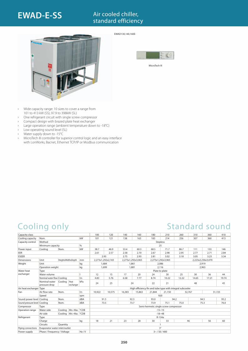
Air cooled chiller, standard efficiency
› Wide capacity range: 10 sizes to cover a range from
101 to 413 kW (SS), 97.9 to 398kW (SL)
› One refrigerant circuit with single screw compressor
› Compact design with brazed plate heat exchanger
› Large operation range (ambient temperature down to -18°C)
› Low operating sound level (SL)
› Water supply down to -15°C
› MicroTech III controller for superior control logic and an easy interface
with LonWorks, Bacnet, Ethernet TCP/IP or Modbus communication
250
101 121 138 163 183 214 256 307 360 413
2538.7 46.9 53.4 60.3 68.5 71.7 86.7 111 133 1462.61 2.57 2.58 2.70 2.67 2.98 2.95 2.77 2.71 2.84
2.93 2.75 2.93 2.81 3.02 3.18 3.05 3.23 3.342,273x1,292x2,165 2,273x1,292x3,065 2,273x1,292x3,965 2,223x2,236x3,070
1,684 1,861 2,086 2,9191,699 1,881 2,116 2,963
12 15 17 20 24 30 25 30 36 444.83 5.76 6.58 7.77 8.74 10.22 12.22 14.65 17.21 19.74
24 25 24 22 21 48 45
10,922 10,575 16,383 15,863 21,844 21,150 32,767 31,725920
91.5 92.3 93.0 94.2 94.5 95.273.5 73.7 73.9 75.1 75.0 75.3 76.0
-15~15-18~48
18 21 23 28 30 33 46 56 6013"
3~ / 50 / 400
250
EWAD-E-SS
EWAD130,140,160E-
MicroTech III
GC_pre2_lowres.pdf 250 30/11/2011 12:31:44
251
Cooling only Low soundCapacity class 100 120 130 160 180 210 250 300 350 400Cooling capacity Nom. kWCapacity control Method Stepless
Minimum capacity %Power input Cooling Nom. kWEERESEERDimensions Unit HeightxWidthxDepth mmWeight Unit kg
Operation weight kgWater heat exchanger
Type Plate to plateWater volume lNominal water fl ow Cooling l/sNominal water pressure drop
Cooling Heat exchanger
kPa
Air heat exchanger Type High effi ciency fi n and tube type with integral subcoolerFan Air fl ow rate Nom. l/s
Speed rpmSound power level Cooling Nom. dBASound pressure level Cooling Nom. dBACompressor Type Semi-hermetic single screw compressorOperation range Water side Cooling Min.~Max. °CDB
Air side Cooling Min.~Max. °CDBRefrigerant Type R-134a
Charge kgCircuits Quantity
Piping connections Evaporator water inlet/outletPower supply Phase / Frequency / Voltage Hz / V
251
97.9 116 134 157 177 209 249 296 345 398
2538.8 47.9 53.0 60.6 67.8 72.1 84.5 110 134 1502.52 2.42 2.53 2.60 2.61 2.89 2.95 2.69 2.58 2.653.01 2.97 2.85 3.00 3.07 3.32 3.55 3.41 3.34 3.452,273x1,292x2,165 2,273x1,292x3,065 2,273x1,292x3,965 2,223x2,236x3,070
1,784 1,961 2,186 3,0291,799 1,981 2,216 3,073
12 15 17 20 24 30 25 30 36 444.68 5.54 6.40 7.51 8.47 9.97 11.90 14.15 16.50 19.01
23 21 20 46 45 44 42
8,372 8,144 12,558 12,217 16,744 16,289 25,117 24,433715
89.0 89.8 90.5 91.7 92.0 92.771.0 71.2 71.4 72.6 72.5 72.8 73.5
-15~15-18~48
18 21 23 28 30 33 46 56 6013"
3~ / 50 / 400
251
EWAD-E-SL
GC_pre2_lowres.pdf 251 30/11/2011 12:31:44
252
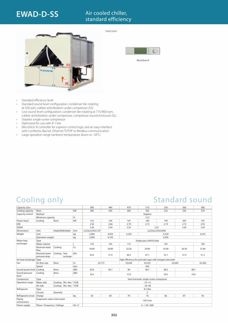
Cooling only Standard soundCapacity class 390 440 470 510 530 560 580Cooling capacity Nom. kWCapacity control Method Stepless
Minimum capacity %Power input Cooling Nom. kWEERESEERDimensions Unit HeightxWidthxDepth mmWeight Unit kg
Operation weight kgWater heat exchanger
Type Single pass shell & tubeWater volume lNominal water flow
Cooling l/s
Nominal water pressure drop
Cooling Heat exchanger
kPa
Air heat exchanger Type High efficiency fin and tube type with integral subcoolerFan Air flow rate Nom. l/s
Speed rpmSound power level Cooling Nom. dBASound pressure level
Cooling Nom. dBA
Compressor Type Semi-hermetic single screw compressorOperation range Water side Cooling Min.~Max. °CDB
Air side Cooling Min.~Max. °CDBRefrigerant Type R-134a
Circuits QuantityRefrigerant circuit Charge kgPiping connections
Evaporator water inlet/outlet
Power supply Phase / Frequency / Voltage Hz / V
› Standard efficiency level
› Standard sound level configuration: condenser fan rotating
at 920 rpm, rubber antivibration under compressor (SS)
› Low sound level configuration: condenser fan rotating at 715/900 rpm,
rubber antivibration under compressor, compressor sound enclosure (SL)
› Stepless single-screw compressor
› Optimised for use with R-134a
› MicroTech III controller for superior control logic and an easy interface
with LonWorks, Bacnet, Ethernet TCP/IP or Modbus communication
› Large operation range (ambient temperature down to -18°C)
Air cooled chiller, standard efficiency
252
389 436 466 502 532 556 578
12.5152 164 167 184 194 205 1972.56 2.66 2.79 2.73 2.74 2.72 2.933.36 3.54 3.55 3.52 3.56 3.39
2,223x2,234x3,139 2,223x2,234x4,0402,960 4,030 4,220 4,230 4,2353,090 4,195 4,395
130 165 175 165 160
18.60 20.80 22.20 24.00 25.40 26.50 27.60
45.6 37.9 66.5 47.1 52.1 57.4 51.2
32,772 43,694 43,455 43,694 42,300920
95.8 96.7 96 96.7 98.2 98.7
76.5 77.0 78.5 79.0
-15~15-18~48
256 60 70 76 82 87 92
139.7mm
3~ / 50 / 400
252
EWAD-D-SS
EWAD390D-
MicroTech III
GC_pre2_lowres.pdf 252 30/11/2011 12:31:44
253
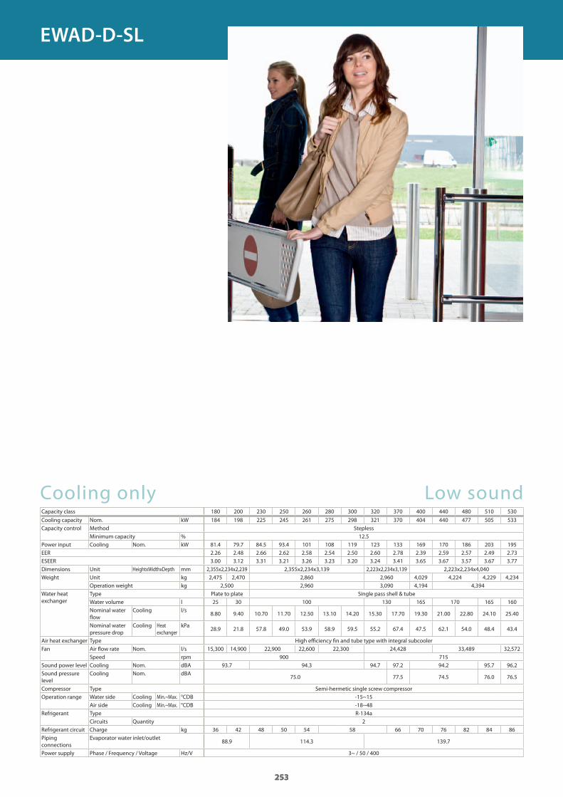
Cooling only Low soundCapacity class 180 200 230 250 260 280 300 320 370 400 440 480 510 530
Cooling capacity Nom. kWCapacity control Method Stepless
Minimum capacity %Power input Cooling Nom. kWEERESEERDimensions Unit HeightxWidthxDepth mmWeight Unit kg
Operation weight kgWater heat exchanger
Type Plate to plate Single pass shell & tubeWater volume lNominal water flow
Cooling l/s
Nominal water pressure drop
Cooling Heat exchanger
kPa
Air heat exchanger Type High efficiency fin and tube type with integral subcoolerFan Air flow rate Nom. l/s
Speed rpmSound power level Cooling Nom. dBASound pressure level
Cooling Nom. dBA
Compressor Type Semi-hermetic single screw compressorOperation range Water side Cooling Min.~Max. °CDB
Air side Cooling Min.~Max. °CDBRefrigerant Type R-134a
Circuits QuantityRefrigerant circuit Charge kgPiping connections
Evaporator water inlet/outlet
Power supply Phase / Frequency / Voltage Hz/V
253
184 198 225 245 261 275 298 321 370 404 440 477 505 533
12.581.4 79.7 84.5 93.4 101 108 119 123 133 169 170 186 203 1952.26 2.48 2.66 2.62 2.58 2.54 2.50 2.60 2.78 2.39 2.59 2.57 2.49 2.733.00 3.12 3.31 3.21 3.26 3.23 3.20 3.24 3.41 3.65 3.67 3.57 3.67 3.77
2,355x2,234x2,239 2,355x2,234x3,139 2,223x2,234x3,139 2,223x2,234x4,0402,475 2,470 2,860 2,960 4,029 4,224 4,229 4,234
2,500 2,960 3,090 4,194 4,394
25 30 100 130 165 170 165 160
8.80 9.40 10.70 11.70 12.50 13.10 14.20 15.30 17.70 19.30 21.00 22.80 24.10 25.40
28.9 21.8 57.8 49.0 53.9 58.9 59.5 55.2 67.4 47.5 62.1 54.0 48.4 43.4
15,300 14,900 22,900 22,600 22,300 24,428 33,489 32,572900 715
93.7 94.3 94.7 97.2 94.2 95.7 96.2
75.0 77.5 74.5 76.0 76.5
-15~15-18~48
236 42 48 50 54 58 66 70 76 82 84 86
88.9 114.3 139.7
3~ / 50 / 400
253
EWAD-D-SL
GC_pre2_lowres.pdf 253 30/11/2011 12:31:44
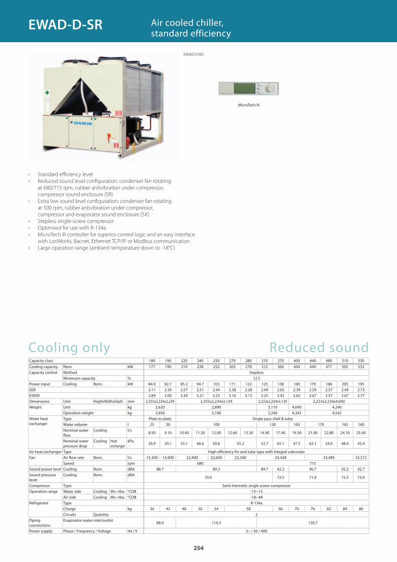
254
Cooling only Reduced soundCapacity class 180 190 220 240 250 270 280 310 370 400 440 480 510 530
Cooling capacity Nom. kWCapacity control Method Stepless
Minimum capacity %Power input Cooling Nom. kWEERESEERDimensions Unit HeightxWidthxDepth mmWeight Unit kg
Operation weight kgWater heat exchanger
Type Plate to plate Single pass shell & tubeWater volume lNominal water flow
Cooling l/s
Nominal water pressure drop
Cooling Heat exchanger
kPa
Air heat exchanger Type High efficiency fin and tube type with integral subcoolerFan Air flow rate Nom. l/s
Speed rpmSound power level Cooling Nom. dBASound pressure level
Cooling Nom. dBA
Compressor Type Semi-hermetic single screw compressorOperation range Water side Cooling Min.~Max. °CDB
Air side Cooling Min.~Max. °CDBRefrigerant Type R-134a
Charge kgCircuits Quantity
Piping connections
Evaporator water inlet/outlet
Power supply Phase / Frequency / Voltage Hz / V
› Standard efficiency level
› Reduced sound level configuration: condenser fan rotating
at 680/715 rpm, rubber antivibration under compressor,
compressor sound enclosure (SR)
› Extra low sound level configuration: condenser fan rotating
at 500 rpm, rubber antivibration under compressor,
compressor and evaporator sound enclosure (SX)
› Stepless single-screw compressor
› Optimised for use with R-134a
› MicroTech III controller for superior control logic and an easy interface
with LonWorks, Bacnet, Ethernet TCP/IP or Modbus communication
› Large operation range (ambient temperature down to -18°C)
Air cooled chiller, standard efficiency
254
177 190 219 238 252 265 278 312 366 404 440 477 505 533
12.584.0 82.7 85.2 94.7 103 111 122 125 138 169 170 186 203 1952.11 2.30 2.57 2.51 2.44 2.38 2.28 2.49 2.65 2.39 2.59 2.57 2.49 2.732.89 3.00 3.34 3.21 3.23 3.16 3.13 3.25 3.42 3.65 3.67 3.57 3.67 3.77
2,355x2,234x2,239 2,355x2,234x3,139 2,223x2,234x3,139 2,223x2,234x4,0402,620 2,890 3,110 4,040 4,2402,650 3,100 3,240 4,342 4,542
25 30 100 130 165 170 165 160
8.50 9.10 10.40 11.30 12.00 12.60 13.30 14.90 17.40 19.30 21.00 22.80 24.10 25.40
26.9 20.1 55.1 46.6 50.8 55.2 52.7 65.1 47.5 62.1 54.0 48.4 43.4
15,300 14,900 22,900 22,600 22,300 24,428 33,489 32,572680 715
88.7 89.3 89.7 92.2 90.7 92.2 92.7
70.0 72.5 71.0 72.5 73.0
-15~15-18~48
36 42 48 50 54 58 66 70 76 82 84 862
88.9 114.3 139.7
3~ / 50 / 400
254
EWAD-D-SR
EWAD370D-
MicroTech III
GC_pre2_lowres.pdf 254 30/11/2011 12:31:45
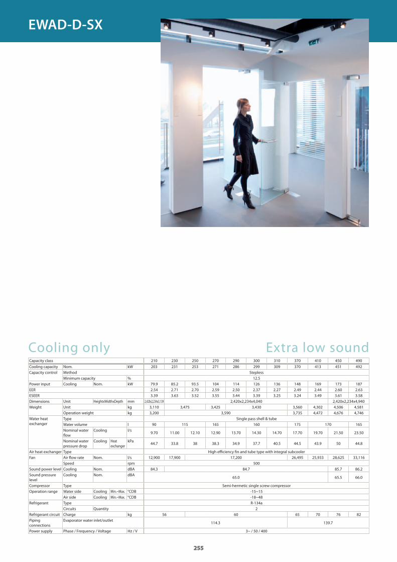
255
Cooling only Extra low soundCapacity class 210 230 250 270 290 300 310 370 410 450 490
Cooling capacity Nom. kWCapacity control Method Stepless
Minimum capacity %Power input Cooling Nom. kWEERESEERDimensions Unit HeightxWidthxDepth mmWeight Unit kg
Operation weight kgWater heat exchanger
Type Single pass shell & tubeWater volume lNominal water flow
Cooling l/s
Nominal water pressure drop
Cooling Heat exchanger
kPa
Air heat exchanger Type High efficiency fin and tube type with integral subcoolerFan Air flow rate Nom. l/s
Speed rpmSound power level Cooling Nom. dBASound pressure level
Cooling Nom. dBA
Compressor Type Semi-hermetic single screw compressorOperation range Water side Cooling Min.~Max. °CDB
Air side Cooling Min.~Max. °CDBRefrigerant Type R-134a
Circuits QuantityRefrigerant circuit Charge kgPiping connections
Evaporator water inlet/outlet
Power supply Phase / Frequency / Voltage Hz / V
255
203 231 253 271 286 299 309 370 413 451 492
12.579.9 85.2 93.5 104 114 126 136 148 169 173 187 2.54 2.71 2.70 2.59 2.50 2.37 2.27 2.49 2.44 2.60 2.63 3.39 3.63 3.52 3.55 3.44 3.39 3.25 3.24 3.49 3.61 3.58
2,420x2,234x3,139 2,420x2,234x4,040 2,420x2,234x4,9403,110 3,475 3,425 3,430 3,560 4,302 4,506 4,5813,200 3,590 3,735 4,472 4,676 4,746
90 115 165 160 175 170 165
9.70 11.00 12.10 12.90 13.70 14.30 14.70 17.70 19.70 21.50 23.50
44.7 33.8 38 38.3 34.9 37.7 40.5 44.5 43.9 50 44.8
12,900 17,900 17,200 26,495 25,933 28,625 33,116500
84.3 84.7 85.7 86.2
65.0 65.5 66.0
-15~15-18~48
256 60 65 70 76 82
114.3 139.7
3~ / 50 / 400
255
EWAD-D-SX
GC_pre2_lowres.pdf 255 30/11/2011 12:31:45
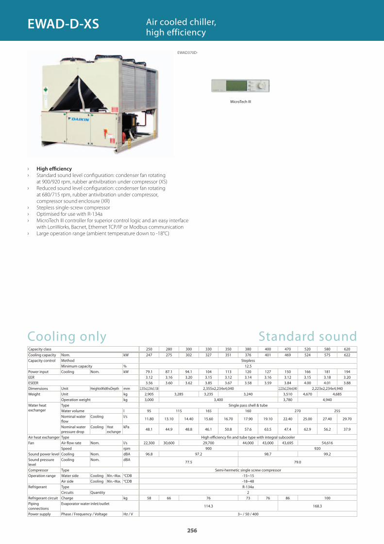
256
Cooling only Standard soundCapacity class 250 280 300 330 350 380 400 470 520 580 620
Cooling capacity Nom. kWCapacity control Method Stepless
Minimum capacity %Power input Cooling Nom. kWEERESEERDimensions Unit HeightxWidthxDepth mmWeight Unit kg
Operation weight kgWater heat exchanger
Type Single pass shell & tubeWater volume lNominal water flow
Cooling l/s
Nominal water pressure drop
Cooling Heat exchanger
kPa
Air heat exchanger Type High efficiency fin and tube type with integral subcoolerFan Air flow rate Nom. l/s
Speed rpmSound power level Cooling Nom. dBASound pressure level
Cooling Nom. dBA
Compressor Type Semi-hermetic single screw compressorOperation range Water side Cooling Min.~Max. °CDB
Air side Cooling Min.~Max. °CDBRefrigerant Type R-134a
Circuits QuantityRefrigerant circuit Charge kgPiping connections
Evaporator water inlet/outlet
Power supply Phase / Frequency / Voltage Hz / V
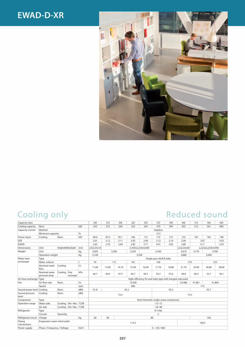
› High efficiency
› Standard sound level configuration: condenser fan rotating
at 900/920 rpm, rubber antivibration under compressor (XS)
› Reduced sound level configuration: condenser fan rotating
at 680/715 rpm, rubber antivibration under compressor,
compressor sound enclosure (XR)
› Stepless single-screw compressor
› Optimised for use with R-134a
› MicroTech III controller for superior control logic and an easy interface
with LonWorks, Bacnet, Ethernet TCP/IP or Modbus communication
› Large operation range (ambient temperature down to -18°C)
Air cooled chiller, high efficiency
256
247 275 302 327 351 376 401 469 524 575 622
12.579.1 87.1 94.1 104 113 120 127 150 166 181 194 3.12 3.16 3.20 3.15 3.12 3.14 3.16 3.12 3.15 3.18 3.20 3.56 3.60 3.62 3.85 3.67 3.58 3.59 3.84 4.00 4.01 3.88
2,355x2,234x3,138 2,355x2,234x4,040 2,223x2,234x4,040 2,223x2,234x4,9402,905 3,285 3,235 3,240 3,510 4,670 4,6853,000 3,400 3,780 4,940
95 115 165 160 270 255
11.80 13.10 14.40 15.60 16.70 17.90 19.10 22.40 25.00 27.40 29.70
48.1 44.9 48.8 46.1 50.8 57.6 63.5 47.4 62.9 56.2 37.9
22,300 30,600 29,700 44,000 43,000 43,695 54,616900 920
96.8 97.2 98.7 99.2
77.5 79.0
-15~15-18~48
258 66 76 73 76 86 100
114.3 168.3
3~ / 50 / 400
256
EWAD-D-XS
EWAD370D-
MicroTech III
GC_pre2_lowres.pdf 256 30/11/2011 12:31:45
257
Cooling only Reduced soundCapacity class 240 270 300 320 350 370 390 460 510 560 600
Cooling capacity Nom. kWCapacity control Method Stepless
Minimum capacity %Power input Cooling Nom. kWEERESEERDimensions Unit HeightxWidthxDepth mmWeight Unit kg
Operation weight kgWater heat exchanger
Type Single pass shell & tubeWater volume lNominal water flow
Cooling l/s
Nominal water pressure drop
Cooling Heat exchanger
kPa
Air heat exchanger Type High efficiency fin and tube type with integral subcoolerFan Air flow rate Nom. l/s
Speed rpmSound power level Cooling Nom. dBASound pressure level
Cooling Nom. dBA
Compressor Type Semi-hermetic single screw compressorOperation range Water side Cooling Min.~Max. °CDB
Air side Cooling Min.~Max. °CDBRefrigerant Type R-134a
Circuits QuantityRefrigerant circuit Charge kgPiping connections
Evaporator water inlet/outlet
Power supply Phase / Frequency / Voltage Hz/V
257
243 272 296 322 345 370 394 455 512 561 600
12.580.6 87.0 95.1 106 115 119 127 152 167 183 198 3.01 3.12 3.11 3.05 2.99 3.12 3.10 2.99 3.07 3.03 3.63 3.70 3.69 3.82 3.71 4.01 3.82 3.89 4.11 3.93
2,355x2,234x3,138 2,355x2,234x4,040 2,223x2,234x4,040 2,223x2,234x4,9403,005 3,385 3,335 3,340 3,610 4,770 4,7853,100 3,500 3,880 5,040
95 115 165 160 270 255
11.60 13.00 14.10 15.40 16.40 17.70 18.80 21.70 24.40 26.80 28.60
46.7 44.0 47.5 44.7 49.2 56.2 55.6 44.8 60.4 53.7 36.1
12,500 33,488 41,861 41,864680 715
91.8 92.2 93.2 93.7
72.5 73.5
-15~15-18~48
260 68 80 104
114.3 168.3
3~ / 50 / 400
257
EWAD-D-XR
GC_pre2_lowres.pdf 257 30/11/2011 12:31:45
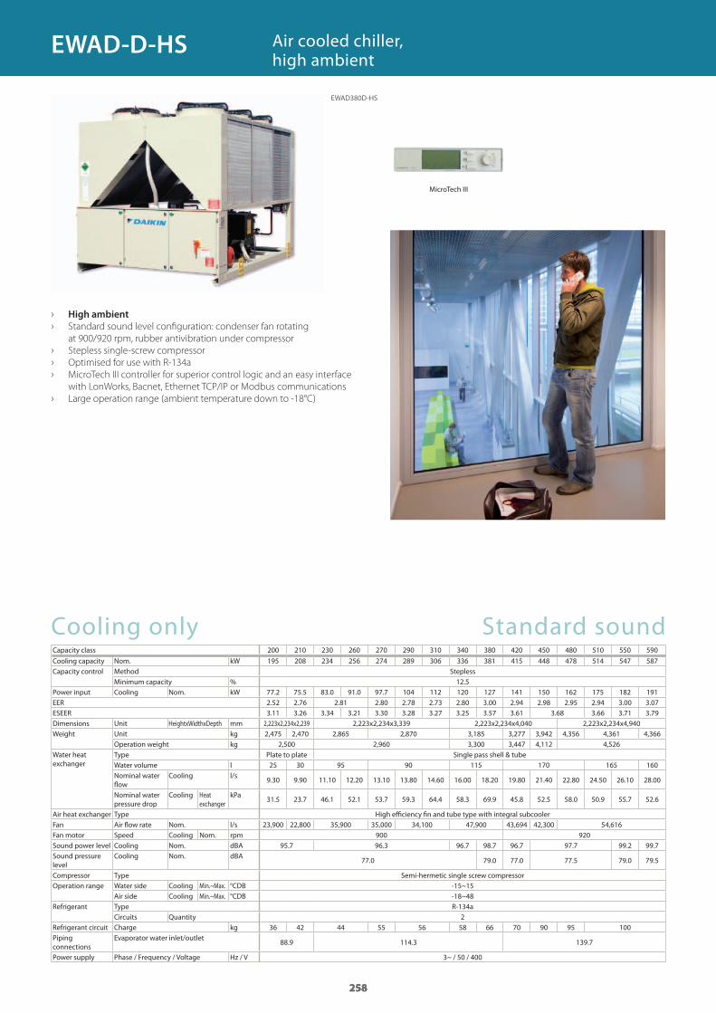
258
Cooling only Standard soundCapacity class 200 210 230 260 270 290 310 340 380 420 450 480 510 550 590
Cooling capacity Nom. kWCapacity control Method Stepless
Minimum capacity %Power input Cooling Nom. kWEERESEERDimensions Unit HeightxWidthxDepth mmWeight Unit kg
Operation weight kgWater heat exchanger
Type Plate to plate Single pass shell & tubeWater volume lNominal water flow
Cooling l/s
Nominal water pressure drop
Cooling Heat exchanger
kPa
Air heat exchanger Type High efficiency fin and tube type with integral subcoolerFan Air flow rate Nom. l/sFan motor Speed Cooling Nom. rpmSound power level Cooling Nom. dBASound pressure level
Cooling Nom. dBA
Compressor Type Semi-hermetic single screw compressorOperation range Water side Cooling Min.~Max. °CDB
Air side Cooling Min.~Max. °CDBRefrigerant Type R-134a
Circuits QuantityRefrigerant circuit Charge kgPiping connections
Evaporator water inlet/outlet
Power supply Phase / Frequency / Voltage Hz / V
› High ambient
› Standard sound level configuration: condenser fan rotating
at 900/920 rpm, rubber antivibration under compressor
› Stepless single-screw compressor
› Optimised for use with R-134a
› MicroTech III controller for superior control logic and an easy interface
with LonWorks, Bacnet, Ethernet TCP/IP or Modbus communications
› Large operation range (ambient temperature down to -18°C)
Air cooled chiller, high ambient
258
195 208 234 256 274 289 306 336 381 415 448 478 514 547 587
12.577.2 75.5 83.0 91.0 97.7 104 112 120 127 141 150 162 175 182 191 2.52 2.76 2.81 2.80 2.78 2.73 2.80 3.00 2.94 2.98 2.95 2.94 3.00 3.07 3.11 3.26 3.34 3.21 3.30 3.28 3.27 3.25 3.57 3.61 3.68 3.66 3.71 3.792,223x2,234x2,239 2,223x2,234x3,339 2,223x2,234x4,040 2,223x2,234x4,9402,475 2,470 2,865 2,870 3,185 3,277 3,942 4,356 4,361 4,366
2,500 2,960 3,300 3,447 4,112 4,526
25 30 95 90 115 170 165 160
9.30 9.90 11.10 12.20 13.10 13.80 14.60 16.00 18.20 19.80 21.40 22.80 24.50 26.10 28.00
31.5 23.7 46.1 52.1 53.7 59.3 64.4 58.3 69.9 45.8 52.5 58.0 50.9 55.7 52.6
23,900 22,800 35,900 35,000 34,100 47,900 43,694 42,300 54,616900 920
95.7 96.3 96.7 98.7 96.7 97.7 99.2 99.7
77.0 79.0 77.0 77.5 79.0 79.5
-15~15-18~48
236 42 44 55 56 58 66 70 90 95 100
88.9 114.3 139.7
3~ / 50 / 400
258
EWAD-D-HS
EWAD380D-HS
MicroTech III
GC_pre2_lowres.pdf 258 30/11/2011 12:31:46
259
GC_pre2_lowres.pdf 259 30/11/2011 12:31:46
260
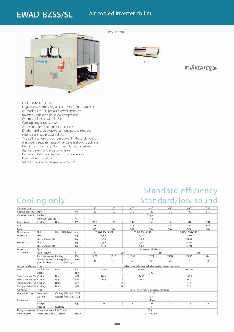
Standard efficiency Cooling only Standard/low soundCapacity class 330 360 400 420 460 490 520Cooling capacity Nom. kWCapacity control Method Stepless
Minimum capacity %Power input Cooling Nom. kWEERESEERDimensions Unit HeightxWidthxDepth mmWeight (SS) Unit kg
Operation weight kgWeight (SL) Unit kg
Operation weight kgWater heat exchanger
Type Single pass shell & tubeWater volume lNominal water flow Cooling l/sNominal water pressure drop
Cooling Heat exchanger
kPa
Air heat exchanger Type High efficiency fin and tube type with integral subcoolerFan Air flow rate Nom. l/s
Speed rpmSound power level (SS) Cooling Nom. dBASound power level (SL) Cooling Nom. dBASound pressure level (SS) Cooling Nom. dBASound pressure level (SL) Cooling Nom. dBACompressor Type Semi-hermetic single screw compressorOperation range Water side Cooling Min.~Max. °CDB
Air side Cooling Min.~Max. °CDBRefrigerant Type R-134a
Charge kgCircuits Quantity
Piping connections Evaporator water inlet/outlet 168.3mmPower supply Phase / Frequency / Voltage Hz / V
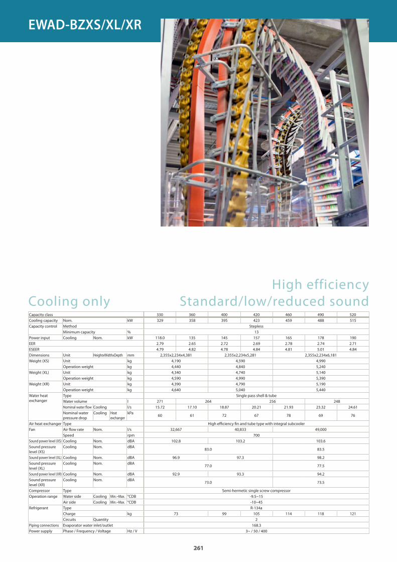
› ESEER up to 4.70 (SS/SL)
› High seasonal efficiency (ESEER up to 5.01) (XS/XL/XR)
› All models are PED pressure vessel approved
› Inverter stepless single-screw compressor
› Optimised for use with R-134a
› Cooling range: 329-515kW
› 2 truly independent refrigerant circuits
› DX shell and tube evaporator – one pass refrigerant
side to minimize pressure drops
› The ability to vary the output power in direct relation to
the cooling requirements of the system allows to achieve
building comfort conditions much faster at start-up
› Standard electronic expansion valve
› Partial and total heat recovery option available
› Power factor over 0.95
› Standard operation range down to -10°C
Air cooled inverter chiller
260
329 358 395 423 459 488 515
13.5120.0 136 147 159 168 181 1932.74 2.63 2.69 2.66 2.73 2.70 2.674.59 4.60 4.55 4.59 4.57 4.70 4.602,355x2,234x4,381 2,355x2,234x5,281 2,355x2,234x6,181
4,190 4,590 4,9904,440 4,840 5,2404,340 4,740 5,1404,590 4,990 5,390
271 264 256 24815.72 17.10 18.87 20.21 21.93 23.32 24.61
60 61 72 67 78 69 76
32,667 40,833 49,000700
102.8 103.2 103.696.9 97.3 98.2
83.0 83.577.0 77.5
-9.5~15-10~45
73 99 105 114 118 1212
3~ / 50 / 400
260
EWAD330,360BZ
PCO2
EWAD-BZSS/SL
GC_pre2_lowres.pdf 260 30/11/2011 12:31:47
261
High efficiency Cooling only Standard/low/reduced sound Capacity class 330 360 400 420 460 490 520Cooling capacity Nom. kWCapacity control Method Stepless
Minimum capacity %Power input Cooling Nom. kWEERESEERDimensions Unit HeightxWidthxDepth mmWeight (XS) Unit kg
Operation weight kgWeight (XL) Unit kg
Operation weight kgWeight (XR) Unit kg
Operation weight kgWater heat exchanger
Type Single pass shell & tubeWater volume lNominal water fl ow Cooling l/sNominal water pressure drop
Cooling Heat exchanger
kPa
Air heat exchanger Type High effi ciency fi n and tube type with integral subcoolerFan Air fl ow rate Nom. l/s
Speed rpmSound power level (XS) Cooling Nom. dBASound pressure level (XS)
Cooling Nom. dBA
Sound power level (XL) Cooling Nom. dBASound pressure level (XL)
Cooling Nom. dBA
Sound power level (XR) Cooling Nom. dBASound pressure level (XR)
Cooling Nom. dBA
Compressor Type Semi-hermetic single screw compressorOperation range Water side Cooling Min.~Max. °CDB
Air side Cooling Min.~Max. °CDBRefrigerant Type R-134a
Charge kgCircuits Quantity
Piping connections Evaporator water inlet/outletPower supply Phase / Frequency / Voltage Hz / V
261
329 358 395 423 459 488 515
13118.0 135 145 157 165 178 190 2.79 2.65 2.72 2.69 2.78 2.74 2.71 4.79 4.82 4.78 4.84 4.81 5.01 4.842,355x2,234x4,381 2,355x2,234x5,281 2,355x2,234x6,181
4,190 4,590 4,9904,440 4,840 5,2404,340 4,740 5,1404,590 4,990 5,3904,390 4,790 5,1904,640 5,040 5,440
271 264 256 24815.72 17.10 18.87 20.21 21.93 23.32 24.61
60 61 72 67 78 69 76
32,667 40,833 49,000700
102.8 103.2 103.6
83.0 83.5
96.9 97.3 98.2
77.0 77.5
92.9 93.3 94.2
73.0 73.5
-9.5~15-10~45
73 99 105 114 118 1212
168.33~ / 50 / 400
261
EWAD-BZXS/XL/XR
GC_pre2_lowres.pdf 261 30/11/2011 12:31:47
262
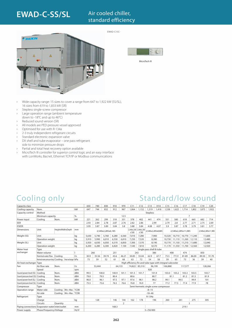
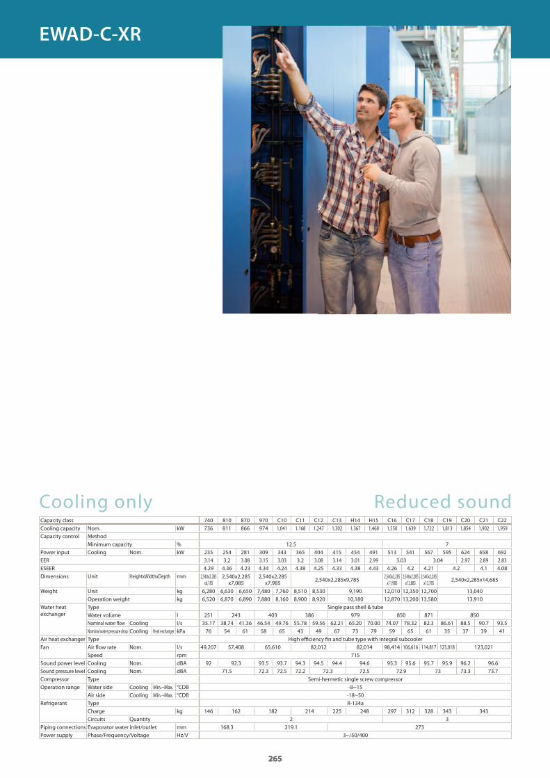
650 740 830 910 970 C11 C12 C13 H14 C15 C16 C17 C18 C19 C20647 744 832 912 967 1,064 1,152 1,319 1,418 1,538 1,622 1,714 1,802 1,875 1,922
12.5 7221 262 299 318 351 378 402 441 474 551 580 618 665 682 714 2.93 2.84 2.78 2.87 2.76 2.82 2.86 2.99 2.79 2.8 2.77 2.71 2.75 2.69 3.95 3.87 3.89 3.84 3.8 3.88 3.84 4.08 4.07 3.9 3.87 3.78 3.79 3.81 3.77
2,540x2,285x6,1852,540x2,285
x7,0852,540x2,285
x7,985 2,540x2,285x8,885 2,540x2,285x11,085 2,540x2,285x11,985
5,630 5,740 5,760 6,280 6,560 7,010 7,280 7,900 10,320 10,710 10,770 11,240 11,6005,910 5,990 6,010 6,530 6,810 7,250 7,520 8,280 10,730 11,110 11,260 12,110 12,4805,920 6,030 6,050 6,570 6,850 7,300 7,570 8,190 10,770 11,150 11,210 11,680 12,0406,200 6,280 6,300 6,820 7,100 7,540 7,810 8,570 11,170 11,550 11,700 12,560 12,920
266 251 243 386 408 474 85030.9 35.56 39.74 43.6 46.21 50.85 55.04 62.9 67.7 73.5 77.51 81.89 86.00 89.50 91.7073 59 52 61 68 63 72 54 58 59 65 73 36 39 40
53,444 64,133 74,822 85,510 96,199 106,888 117,577 128,266920
99.5 100.0 100.9 101.1 101.5 101.7 101.9 103.0 103.2 103.3 103.5 103.779.0 79.5 80.4 80.6 80.7 81.1 81.2 81.5 81.996.0 96.1 97.5 97.1 97.6 98.1 98.2 99.1 99.5 99.9 10175.5 75.6 76.5 76.6 76.8 76.9 77 77.2 77.3 77.4 77.9 78
-8~15-18~46
128 146 144 162 178 196 260 261 275 3052 3
168.3 219.13~/50/400
262
Cooling onlyCapacity classCooling capacity Nom. kWCapacity control Method Stepless
Minimum capacity %Power input Cooling Nom. kWEERESEERDimensions Unit HeightxWidthxDepth mm
Weight (SS) Unit kgOperation weight kg
Weight (SL) Unit kgOperation weight kg
Water heat exchanger
Type Single pass shell & tubeWater volume lNominal water flow Cooling l/sNominal water pressure drop Cooling Heat exchanger kPa
Air heat exchanger Type High efficiency fin and tube type with integral subcoolerFan Air flow rate Nom. l/s
Speed rpmSound power level (SS) Cooling Nom. dBASound pressure level (SS) Cooling Nom. dBASound power level (SL) Cooling Nom. dBASound pressure level (SL) Cooling Nom. dBACompressor Type Semi-hermetic single screw compressorOperation range Water side Cooling Min.~Max. °CDB
Air side Cooling Min.~Max. °CDBRefrigerant Type R-134a
Charge kgCircuits Quantity
Piping connections Evaporator water inlet/outlet mmPower supply Phase/Frequency/Voltage Hz/V
› Wide capacity range: 15 sizes to cover a range from 647 to 1,922 kW (SS/SL),
16 sizes from 619 to 1,833 kW (SR)
› Stepless single-screw compressor
› Large operation range (ambient temperature
down to -18°C and up to 46°C)
› Reduced sound version (SR)
› All models are PED pressure vessel approved
› Optimised for use with R-134a
› 2-3 truly independent refrigerant circuits
› Standard electronic expansion valve
› DX shell and tube evaporator – one pass refrigerant
side to minimize pressure drops
› Partial and total heat recovery option available
› MicroTech III controller for superior control logic and an easy interface
with LonWorks, Bacnet, Ethernet TCP/IP or Modbus communications
Air cooled chiller, standard efficiency
Standard/low sound
262
EWAD-C15C-
EWAD-C-SS/SL
MicroTech III
GC_pre2_lowres.pdf 262 30/11/2011 12:31:47
263
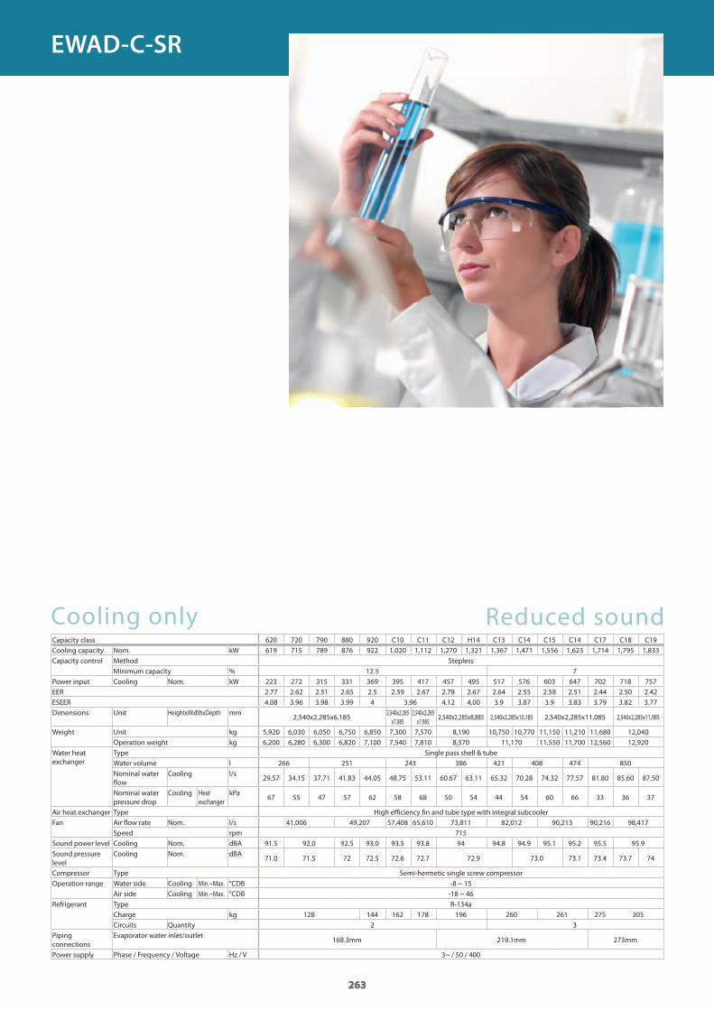
Cooling onlyCapacity class 620 720 790 880 920 C10 C11 C12 H14 C13 C14 C15 C14 C17 C18 C19Cooling capacity Nom. kWCapacity control Method Stepless
Minimum capacity %Power input Cooling Nom. kWEERESEERDimensions Unit HeightxWidthxDepth mm
Weight Unit kgOperation weight kg
Water heat exchanger
Type Single pass shell & tubeWater volume lNominal water fl ow
Cooling l/s
Nominal water pressure drop
Cooling Heat exchanger
kPa
Air heat exchanger Type High effi ciency fi n and tube type with integral subcoolerFan Air fl ow rate Nom. l/s
Speed rpmSound power level Cooling Nom. dBASound pressure level
Cooling Nom. dBA
Compressor Type Semi-hermetic single screw compressorOperation range Water side Cooling Min.~Max. °CDB
Air side Cooling Min.~Max. °CDBRefrigerant Type R-134a
Charge kgCircuits Quantity
Piping connections
Evaporator water inlet/outlet
Power supply Phase / Frequency / Voltage Hz / V
Reduced sound
263
619 715 789 876 922 1,020 1,112 1,270 1,321 1,367 1,471 1,556 1,623 1,714 1,795 1,833
12.5 7223 272 315 331 369 395 417 457 495 517 576 603 647 702 718 757 2.77 2.62 2.51 2.65 2.5 2.59 2.67 2.78 2.67 2.64 2.55 2.58 2.51 2.44 2.50 2.42 4.08 3.96 3.98 3.99 4 3.96 4.12 4.00 3.9 3.87 3.9 3.83 3.79 3.82 3.77
2,540x2,285x6,1852,540x2,285
x7,0852,540x2,285
x7,9852,540x2,285x8,885 2,540x2,285x10,185 2,540x2,285x11,085 2,540x2,285x11,985
5,920 6,030 6,050 6,750 6,850 7,300 7,570 8,190 10,750 10,770 11,150 11,210 11,680 12,0406,200 6,280 6,300 6,820 7,100 7,540 7,810 8,570 11,170 11,550 11,700 12,560 12,920
266 251 243 386 421 408 474 850
29.57 34.15 37.71 41.83 44.05 48.75 53.11 60.67 63.11 65.32 70.28 74.32 77.57 81.80 85.60 87.50
67 55 47 57 62 58 68 50 54 44 54 60 66 33 36 37
41,006 49,207 57,408 65,610 73,811 82,012 90,213 90,216 98,417715
91.5 92.0 92.5 93.0 93.5 93.8 94 94.8 94.9 95.1 95.2 95.5 95.9
71.0 71.5 72 72.5 72.6 72.7 72.9 73.0 73.1 73.4 73.7 74
-8 ~ 15-18 ~ 46
128 144 162 178 196 260 261 275 3052 3
168.3mm 219.1mm 273mm
3~ / 50 / 400
263
EWAD-C-SR
GC_pre2_lowres.pdf 263 30/11/2011 12:31:47
264
Cooling onlyCapacity classCooling capacity Nom. kWCapacity control Method Stepless
Minimum capacity %Power input Cooling Nom. kWEERESEERDimensions Unit HeightxWidthxDepth mm
Weight (XS) Unit kgOperation weight kg
Weight (XL) Unit kgOperation weight kg
Water heat exchanger
Type Single pass shell & tubeWater volume lNominal water flow Cooling l/sNominal water pressure drop Cooling Heat exchanger kPa
Air heat exchanger Type High efficiency fin and tube type with integral subcoolerFan Air flow rate Nom. l/sFan motor Speed Cooling Nom. rpmSound power level (XS) Cooling Nom. dBASound pressure level (XS) Cooling Nom. dBASound power level (XL) Cooling Nom. dBASound pressure level (XL) Cooling Nom. dBACompressor Type Semi-hermetic single screw compressorOperation range Water side Cooling Min.~Max. °CDB
Air side Cooling Min.~Max. °CDBRefrigerant Type R-134a
Charge kgCircuits Quantity
Piping connections Evaporator water inlet/outlet mmPower supply Phase/Frequency/Voltage Hz/V
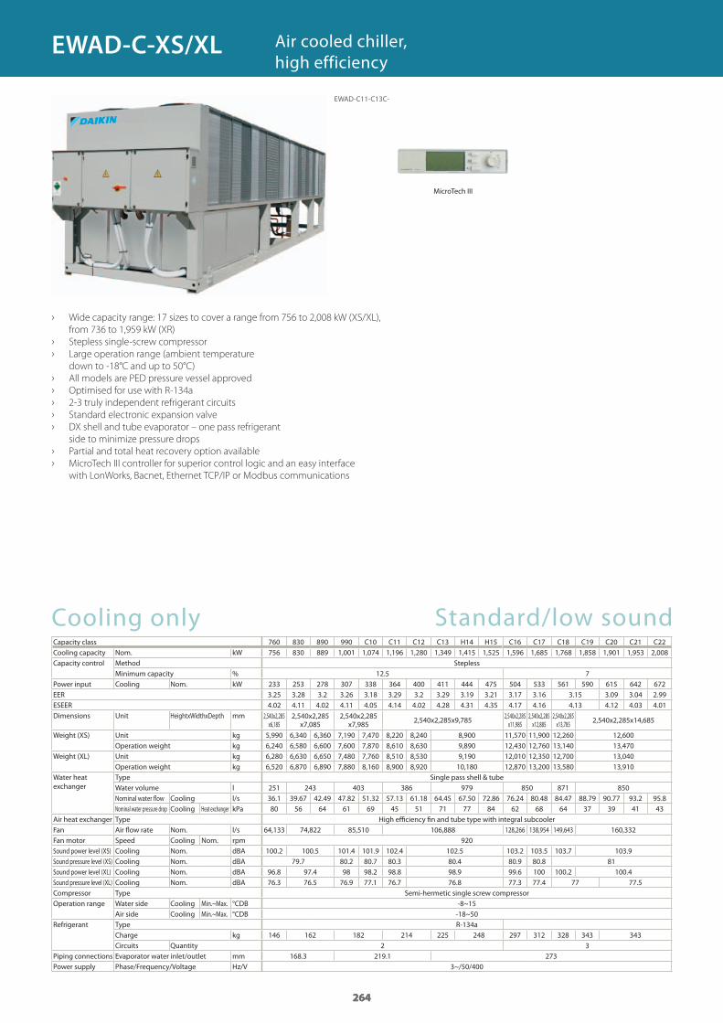
› Wide capacity range: 17 sizes to cover a range from 756 to 2,008 kW (XS/XL),
from 736 to 1,959 kW (XR)
› Stepless single-screw compressor
› Large operation range (ambient temperature
down to -18°C and up to 50°C)
› All models are PED pressure vessel approved
› Optimised for use with R-134a
› 2-3 truly independent refrigerant circuits
› Standard electronic expansion valve
› DX shell and tube evaporator – one pass refrigerant
side to minimize pressure drops
› Partial and total heat recovery option available
› MicroTech III controller for superior control logic and an easy interface
with LonWorks, Bacnet, Ethernet TCP/IP or Modbus communications
Air cooled chiller, high efficiency
Standard/low sound
264
760 830 890 990 C10 C11 C12 C13 H14 H15 C16 C17 C18 C19 C20 C21 C22756 830 889 1,001 1,074 1,196 1,280 1,349 1,415 1,525 1,596 1,685 1,768 1,858 1,901 1,953 2,008
12.5 7233 253 278 307 338 364 400 411 444 475 504 533 561 590 615 642 672 3.25 3.28 3.2 3.26 3.18 3.29 3.2 3.29 3.19 3.21 3.17 3.16 3.15 3.09 3.04 2.99 4.02 4.11 4.02 4.11 4.05 4.14 4.02 4.28 4.31 4.35 4.17 4.16 4.13 4.12 4.03 4.01
2,540x2,285 x6,185
2,540x2,285 x7,085
2,540x2,285 x7,985 2,540x2,285x9,785 2,540x2,285
x11,9852,540x2,285 x12,885
2,540x2,285 x13,785 2,540x2,285x14,685
5,990 6,340 6,360 7,190 7,470 8,220 8,240 8,900 11,570 11,900 12,260 12,6006,240 6,580 6,600 7,600 7,870 8,610 8,630 9,890 12,430 12,760 13,140 13,4706,280 6,630 6,650 7,480 7,760 8,510 8,530 9,190 12,010 12,350 12,700 13,0406,520 6,870 6,890 7,880 8,160 8,900 8,920 10,180 12,870 13,200 13,580 13,910
251 243 403 386 979 850 871 85036.1 39.67 42.49 47.82 51.32 57.13 61.18 64.45 67.50 72.86 76.24 80.48 84.47 88.79 90.77 93.2 95.880 56 64 61 69 45 51 71 77 84 62 68 64 37 39 41 43
64,133 74,822 85,510 106,888 128,266 138,954 149,643 160,332920
100.2 100.5 101.4 101.9 102.4 102.5 103.2 103.5 103.7 103.979.7 80.2 80.7 80.3 80.4 80.9 80.8 81
96.8 97.4 98 98.2 98.8 98.9 99.6 100 100.2 100.476.3 76.5 76.9 77.1 76.7 76.8 77.3 77.4 77 77.5
-8~15-18~50
146 162 182 214 225 248 297 312 328 343 3432 3
168.3 219.1 2733~/50/400
264
EWAD-C11-C13C-
EWAD-C-XS/XL
MicroTech III
GC_pre2_lowres.pdf 264 30/11/2011 12:31:48
265
Cooling onlyCapacity classCooling capacity Nom. kWCapacity control Method
Minimum capacity %Power input Cooling Nom. kWEERESEERDimensions Unit HeightxWidthxDepth mm
Weight Unit kgOperation weight kg
Water heat exchanger
Type Single pass shell & tubeWater volume lNominal water fl ow Cooling l/sNominal water pressure drop Cooling Heat exchanger kPa
Air heat exchanger Type High effi ciency fi n and tube type with integral subcoolerFan Air fl ow rate Nom. l/s
Speed rpmSound power level Cooling Nom. dBASound pressure level Cooling Nom. dBACompressor Type Semi-hermetic single screw compressorOperation range Water side Cooling Min.~Max. °CDB
Air side Cooling Min.~Max. °CDBRefrigerant Type R-134a
Charge kgCircuits Quantity
Piping connections Evaporator water inlet/outlet mmPower supply Phase/Frequency/Voltage Hz/V
Reduced sound
265
740 810 870 970 C10 C11 C12 C13 H14 H15 C16 C17 C18 C19 C20 C21 C22736 811 866 974 1,041 1,168 1,247 1,302 1,367 1,468 1,550 1,639 1,722 1,813 1,854 1,902 1,959
12.5 7235 254 281 309 343 365 404 415 454 491 513 541 567 595 624 658 692 3.14 3.2 3.08 3.15 3.03 3.2 3.08 3.14 3.01 2.99 3.03 3.04 2.97 2.89 2.83 4.29 4.36 4.23 4.34 4.24 4.38 4.25 4.33 4.38 4.43 4.26 4.2 4.21 4.2 4.1 4.08
2,540x2,285 x6,185
2,540x2,285 x7,085
2,540x2,285 x7,985 2,540x2,285x9,785 2,540x2,285
x11,9852,540x2,285 x12,885
2,540x2,285 x13,785 2,540x2,285x14,685
6,280 6,630 6,650 7,480 7,760 8,510 8,530 9,190 12,010 12,350 12,700 13,0406,520 6,870 6,890 7,880 8,160 8,900 8,920 10,180 12,870 13,200 13,580 13,910
251 243 403 386 979 850 871 85035.17 38.74 41.36 46.54 49.76 55.78 59.56 62.21 65.20 70.00 74.07 78.32 82.3 86.61 88.5 90.7 93.576 54 61 58 65 43 49 67 73 79 59 65 61 35 37 39 41
49,207 57,408 65,610 82,012 82,014 98,414 106,616 114,817 123,018 123,021715
92 92.3 93.5 93.7 94.3 94.5 94.4 94.6 95.3 95.6 95.7 95.9 96.2 96.671.5 72.3 72.5 72.2 72.3 72.5 72.9 73 73.3 73.7
-8~15-18~50
146 162 182 214 225 248 297 312 328 343 3432 3
168.3 219.1 2733~/50/400
265
EWAD-C-XR
GC_pre2_lowres.pdf 265 30/11/2011 12:31:48
266
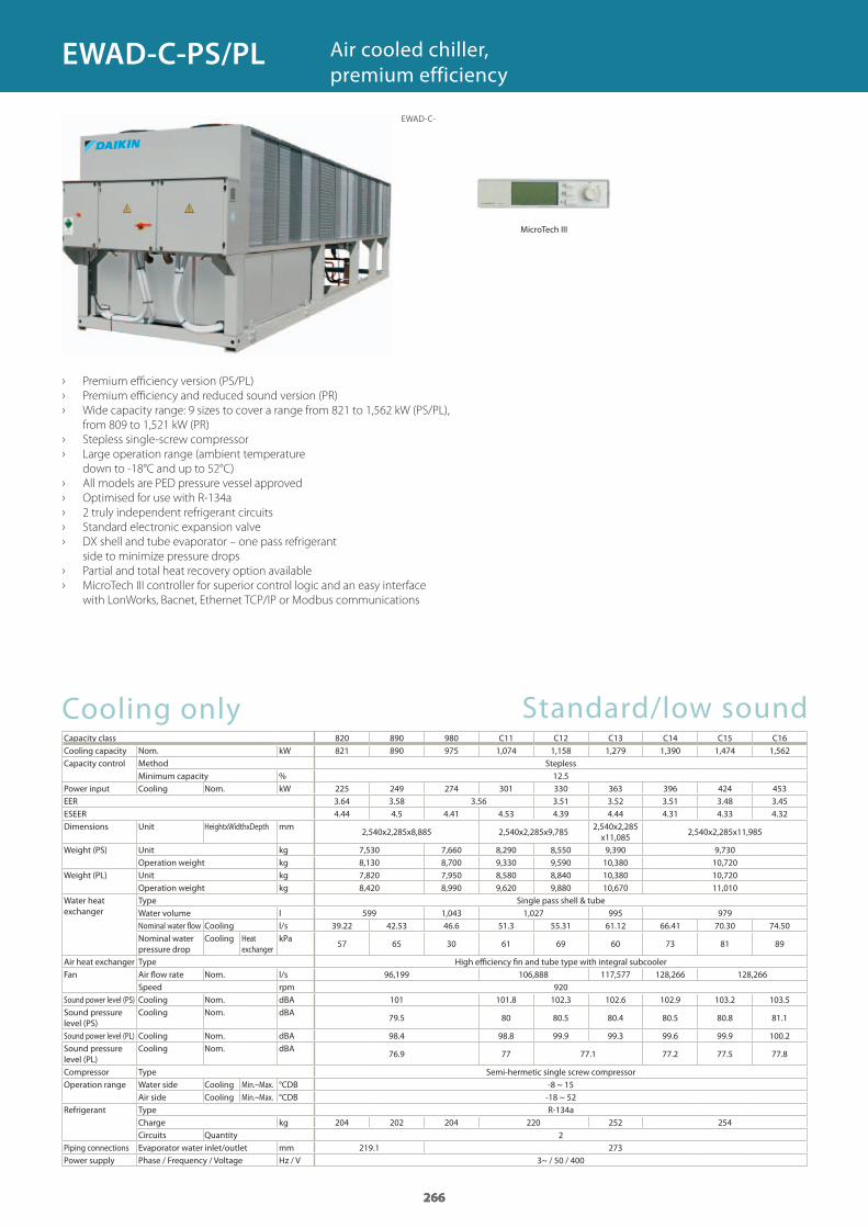
› Premium efficiency version (PS/PL)
› Premium efficiency and reduced sound version (PR)
› Wide capacity range: 9 sizes to cover a range from 821 to 1,562 kW (PS/PL),
from 809 to 1,521 kW (PR)
› Stepless single-screw compressor
› Large operation range (ambient temperature
down to -18°C and up to 52°C)
› All models are PED pressure vessel approved
› Optimised for use with R-134a
› 2 truly independent refrigerant circuits
› Standard electronic expansion valve
› DX shell and tube evaporator – one pass refrigerant
side to minimize pressure drops
› Partial and total heat recovery option available
› MicroTech III controller for superior control logic and an easy interface
with LonWorks, Bacnet, Ethernet TCP/IP or Modbus communications
Air cooled chiller, premium efficiency
Cooling onlyCapacity class 820 890 980 C11 C12 C13 C14 C15 C16Cooling capacity Nom. kWCapacity control Method Stepless
Minimum capacity %Power input Cooling Nom. kWEERESEERDimensions Unit HeightxWidthxDepth mm
Weight (PS) Unit kgOperation weight kg
Weight (PL) Unit kgOperation weight kg
Water heat exchanger
Type Single pass shell & tubeWater volume lNominal water flow Cooling l/sNominal water pressure drop
Cooling Heat exchanger
kPa
Air heat exchanger Type High efficiency fin and tube type with integral subcoolerFan Air flow rate Nom. l/s
Speed rpmSound power level (PS) Cooling Nom. dBASound pressure level (PS)
Cooling Nom. dBA
Sound power level (PL) Cooling Nom. dBASound pressure level (PL)
Cooling Nom. dBA
Compressor Type Semi-hermetic single screw compressorOperation range Water side Cooling Min.~Max. °CDB
Air side Cooling Min.~Max. °CDBRefrigerant Type R-134a
Charge kgCircuits Quantity
Piping connections Evaporator water inlet/outlet mmPower supply Phase / Frequency / Voltage Hz / V
Standard/low sound
266
821 890 975 1,074 1,158 1,279 1,390 1,474 1,562
12.5225 249 274 301 330 363 396 424 453 3.64 3.58 3.56 3.51 3.52 3.51 3.48 3.45 4.44 4.5 4.41 4.53 4.39 4.44 4.31 4.33 4.32
2,540x2,285x8,885 2,540x2,285x9,7852,540x2,285 x11,085
2,540x2,285x11,985
7,530 7,660 8,290 8,550 9,390 9,7308,130 8,700 9,330 9,590 10,380 10,7207,820 7,950 8,580 8,840 10,380 10,7208,420 8,990 9,620 9,880 10,670 11,010
599 1,043 1,027 995 97939.22 42.53 46.6 51.3 55.31 61.12 66.41 70.30 74.50
57 65 30 61 69 60 73 81 89
96,199 106,888 117,577 128,266 128,266920
101 101.8 102.3 102.6 102.9 103.2 103.5
79.5 80 80.5 80.4 80.5 80.8 81.1
98.4 98.8 99.9 99.3 99.6 99.9 100.2
76.9 77 77.1 77.2 77.5 77.8
-8 ~ 15-18 ~ 52
204 202 204 220 252 2542
219.1 2733~ / 50 / 400
266
EWAD-C-
EWAD-C-PS/PL
MicroTech III
GC_pre2_lowres.pdf 266 30/11/2011 12:31:48
267
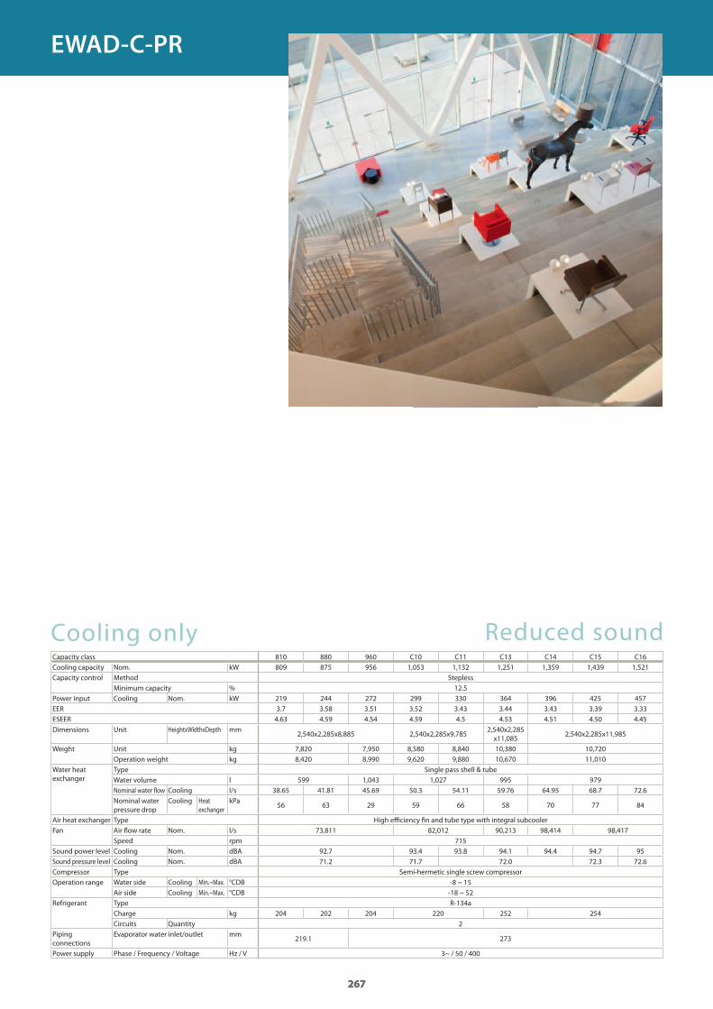
Cooling onlyCapacity class 810 880 960 C10 C11 C13 C14 C15 C16Cooling capacity Nom. kWCapacity control Method Stepless
Minimum capacity %Power input Cooling Nom. kWEERESEERDimensions Unit HeightxWidthxDepth mm
Weight Unit kgOperation weight kg
Water heat exchanger
Type Single pass shell & tubeWater volume lNominal water fl ow Cooling l/sNominal water pressure drop
Cooling Heat exchanger
kPa
Air heat exchanger Type High effi ciency fi n and tube type with integral subcoolerFan Air fl ow rate Nom. l/s
Speed rpmSound power level Cooling Nom. dBASound pressure level Cooling Nom. dBACompressor Type Semi-hermetic single screw compressorOperation range Water side Cooling Min.~Max. °CDB
Air side Cooling Min.~Max. °CDBRefrigerant Type R-134a
Charge kgCircuits Quantity
Piping connections
Evaporator water inlet/outlet mm
Power supply Phase / Frequency / Voltage Hz / V
Reduced sound
267
809 875 956 1,053 1,132 1,251 1,359 1,439 1,521
12.5219 244 272 299 330 364 396 425 457 3.7 3.58 3.51 3.52 3.43 3.44 3.43 3.39 3.33
4.63 4.59 4.54 4.59 4.5 4.53 4.51 4.50 4.45
2,540x2,285x8,885 2,540x2,285x9,7852,540x2,285x11,085
2,540x2,285x11,985
7,820 7,950 8,580 8,840 10,380 10,7208,420 8,990 9,620 9,880 10,670 11,010
599 1,043 1,027 995 97938.65 41.81 45.69 50.3 54.11 59.76 64.95 68.7 72.6
56 63 29 59 66 58 70 77 84
73,811 82,012 90,213 98,414 98,417715
92.7 93.4 93.8 94.1 94.4 94.7 9571.2 71.7 72.0 72.3 72.6
-8 ~ 15-18 ~ 52
204 202 204 220 252 2542
219.1 273
3~ / 50 / 400
267
EWAD-C-PR
GC_pre2_lowres.pdf 267 30/11/2011 12:31:49
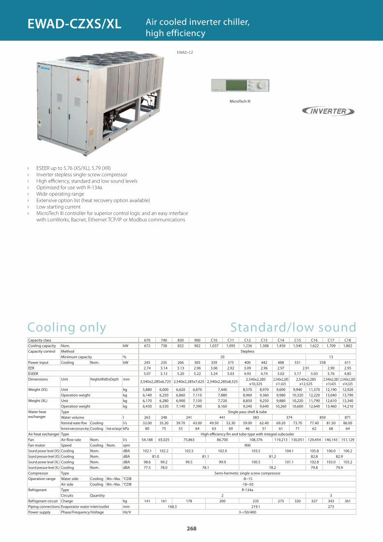
268
Cooling onlyCapacity classCooling capacity Nom. kWCapacity control Method Stepless
Minimum capacity %Power input Cooling Nom. kWEERESEERDimensions Unit HeightxWidthxDepth mm
Weight (XS) Unit kgOperation weight kg
Weight (XL) Unit kgOperation weight kg
Water heat exchanger
Type Single pass shell & tubeWater volume lNominal water flow Cooling l/sNominal water pressure drop Cooling Heat exchanger kPa
Air heat exchanger Type High efficiency fin and tube type with integral subcoolerFan Air flow rate Nom. l/sFan motor Speed Cooling Nom. rpmSound power level (XS) Cooling Nom. dBASound pressure level (XS) Cooling Nom. dBASound power level (XL) Cooling Nom. dBASound pressure level (XL) Cooling Nom. dBACompressor Type Semi-hermetic single screw compressorOperation range Water side Cooling Min.~Max. °CDB
Air side Cooling Min.~Max. °CDBRefrigerant Type R-134a
Circuits QuantityRefrigerant circuit Charge kgPiping connections Evaporator water inlet/outlet mmPower supply Phase/Frequency/Voltage Hz/V
› ESEER up to 5.76 (XS/XL), 5.79 (XR)
› Inverter stepless single-screw compressor
› High efficiency, standard and low sound levels
› Optimised for use with R-134a
› Wide operating range
› Extensive option list (heat recovery option available)
› Low starting current
› MicroTech III controller for superior control logic and an easy interface
with LonWorks, Bacnet, Ethernet TCP/IP or Modbus communications
Air cooled inverter chiller, high efficiency
Standard/low sound
268
670 740 830 900 C10 C11 C12 C13 C14 C15 C16 C17 C18672 738 832 902 1,037 1,095 1,236 1,308 1,450 1,545 1,622 1,709 1,802
20 13245 235 266 305 339 375 400 442 488 531 558 611 2.74 3.14 3.13 2.96 3.06 2.92 3.09 2.96 2.97 2.91 2.90 2.95 5.07 5.13 5.20 5.22 5.24 5.03 4.93 4.74 5.02 5.17 5.03 5.76 4.85
2,540x2,285x6,725 2,540x2,285x7,625 2,540x2,285x8,525 2,540x2,285 x10,325
2,540x2,285 x11,625
2,540x2,285 x12,525
2,540x2,285 x13,425
2,540x2,285 x14,325
5,880 6,000 6,620 6,870 7,440 8,570 8,970 9,600 9,940 11,370 12,190 12,9206,140 6,250 6,860 7,110 7,880 8,960 9,360 9,980 10,320 12,220 13,040 13,7906,170 6,280 6,900 7,150 7,720 8,850 9,250 9,880 10,220 11,790 12,610 13,3406,430 6,530 7,140 7,390 8,160 9,240 9,640 10,260 10,600 12,640 13,460 14,210
263 248 241 441 383 374 850 87132.00 35.20 39.70 43.00 49.50 52.30 59.00 62.40 69.20 73.70 77.40 81.50 86.00
80 75 55 64 63 69 46 51 61 71 62 68 64
54,188 65,025 75,863 86,700 108,376 119,213 130,051 129,454 140,143 151,129900
102.1 102.2 102.5 102.9 103.5 104.1 105.8 106.0 106.281.0 81.1 81.2 82.8 82.9
98.6 99.2 99.5 99.9 100.5 101.1 102.8 103.0 103.277.5 78.0 78.1 78.2 79.8 79.9
-8~15-18~50
2 3141 161 178 200 235 275 320 327 343 361
168.3 219.1 2733~/50/400
268
EWAD-CZ
EWAD-CZXS/XL
MicroTech III
GC_pre2_lowres.pdf 268 30/11/2011 12:31:49
269
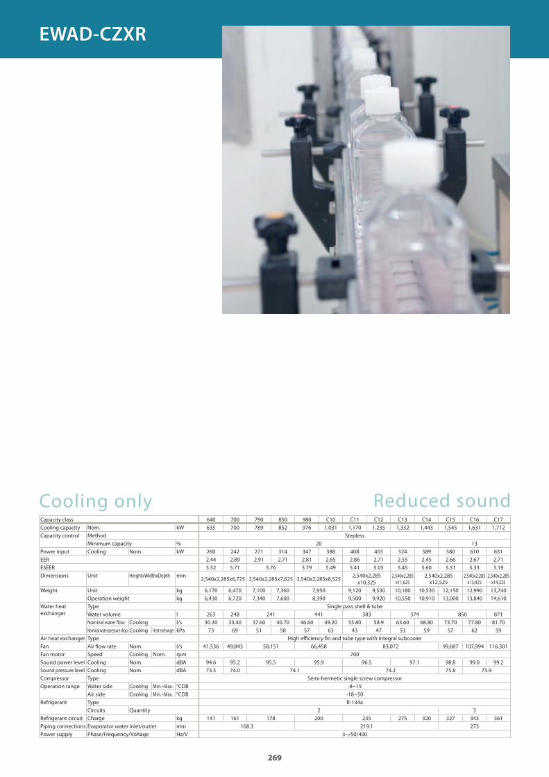
Cooling onlyCapacity classCooling capacity Nom. kWCapacity control Method Stepless
Minimum capacity %Power input Cooling Nom. kWEERESEERDimensions Unit HeightxWidthxDepth mm
Weight Unit kgOperation weight kg
Water heat exchanger
Type Single pass shell & tubeWater volume lNominal water flow Cooling l/sNominal water pressure drop Cooling Heat exchanger kPa
Air heat exchanger Type High efficiency fin and tube type with integral subcoolerFan Air flow rate Nom. l/sFan motor Speed Cooling Nom. rpmSound power level Cooling Nom. dBASound pressure level Cooling Nom. dBACompressor Type Semi-hermetic single screw compressorOperation range Water side Cooling Min.~Max. °CDB
Air side Cooling Min.~Max. °CDBRefrigerant Type R-134a
Circuits QuantityRefrigerant circuit Charge kgPiping connections Evaporator water inlet/outlet mmPower supply Phase/Frequency/Voltage Hz/V
Reduced sound
269
640 700 790 850 980 C10 C11 C12 C13 C14 C15 C16 C17635 700 789 852 976 1,031 1,170 1,235 1,332 1,443 1,545 1,631 1,712
20 13260 242 271 314 347 388 408 455 524 589 580 610 631 2.44 2.89 2.91 2.71 2.81 2.65 2.86 2.71 2.55 2.45 2.66 2.67 2.71 5.52 5.71 5.76 5.79 5.49 5.41 5.05 5.45 5.60 5.51 5.33 5.19
2,540x2,285x6,725 2,540x2,285x7,625 2,540x2,285x8,5252,540x2,285 x10,325
2,540x2,285 x11,625
2,540x2,285 x12,525
2,540x2,285 x13,425
2,540x2,285 x14,325
6,170 6,470 7,100 7,360 7,950 9,120 9,530 10,180 10,530 12,150 12,990 13,7406,430 6,720 7,340 7,600 8,390 9,500 9,920 10,550 10,910 13,000 13,840 14,610
263 248 241 441 383 374 850 87130.30 33.40 37.60 40.70 46.60 49.20 55.80 58.9 63.60 68.80 73.70 77.80 81.7073 69 51 58 57 63 43 47 53 59 57 62 59
41,536 49,843 58,151 66,458 83,072 99,687 107,994 116,301700
94.6 95.2 95.5 95.9 96.5 97.1 98.8 99.0 99.273.5 74.0 74.1 74.2 75.8 75.9
-8~15-18~50
2 3141 161 178 200 235 275 320 327 343 361
168.3 219.1 2733~/50/400
269
EWAD-CZXR
GC_pre2_lowres.pdf 269 30/11/2011 12:31:49
Cooling onlyCapacity classCooling capacity Nom. kW
Mechanical capacity kW
Capacity control Method SteplessMinimum capacity %
Power input Cooling Nom. kW
EER
ESEERDimensions Unit HeightxWidthxDepth mm
Weight Unit kgOperation weight kg
Water heat exchanger
Type Single pass shell & tubeWater volume lNominal water flow Cooling l/sNominal water pressure drop
Cooling Heat exchanger
kPa
Air heat exchanger Type High efficiency fin and tube type with integral subcoolerFan Air flow rate Nom. l/s
Speed rpmSound power level Cooling Nom. dBASound pressure level Cooling Nom. dBACompressor Type Asymm single screwOperation range Water side Cooling Min.~Max. °CDB
Air side Cooling Min.~Max. °CDBRefrigerant Type R-134a
Charge kgCircuits Quantity
Piping connections Evaporator water inlet/outlet mmPower supply Phase/Frequency/Voltage Hz/VAir temperature for free cooling 100% °C
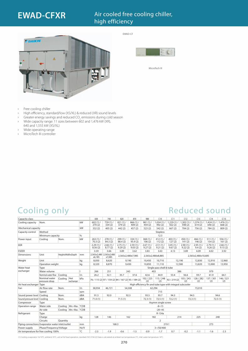
(1) Cooling: evaporator 16/10°C, ambient 35°C, unit at full load operation; standard: ISO 3744 (2) Data is calculated at ambient air temperature 5°C, inlet water temperature 16°C.
› Free cooling chiller
› High efficiency, standard/low (XS/XL) & reduced (XR) sound levels
› Greater energy savings and reduced CO2 emissions during cold season
› Wide capacity range: 11 sizes between 602 and 1,476 kW (XR),
640 and 1,555 kW (XS/XL)
› Wide operating range
› MicroTech III controller
Air cooled free cooling chiller, high efficiency
Reduced sound600 740 820 870 980 C10 C11 C12 C13 C14 C15
602 (1) / 270 (2)
739 (1) / 334 (2)
821 (1) / 379 (2)
866 (1) / 409 (2)
981 (1) / 459 (2)
1,034 (1) / 492 (2)
1,229 (1) / 562 (2)
1,302 (1) / 598 (2)
1,374 (1) / 619 (2)
1,424 (1) / 640 (2)
1,476 (1) / 668 (2)
332 (2) 405 (2) 442 (2) 457 (2) 523 (2) 542 (2) 667 (2) 704 (2) 756 (2) 784 (2) 809 (2)
12.5263 (1) / 70.3 (2)
278 (1) / 84.3 (2)
299 (1) / 88.4 (2)
334 (1) / 95.9 (2)
368 (1) / 106 (2)
412 (1) / 112 (2)
403 (1) / 127 (2)
450 (1) / 141 (2)
466 (1) / 146 (2)
511 (1) / 154 (2)
556 (1) / 161 (2)
2.29 (1) / 8.56 (2)
2.66 (1) / 8.77 (2)
2.75 (1) / 9.29 (2)
2.59 (1) / 9.03 (2)
2.67 (1) / 9.27 (2)
2.51 (1) / 9.21 (2)
3.05 (1) / 9.67 (2)
2.90 (1) / 9.22 (2)
2.95 (1) / 9.4 (2)
2.79 (1) / 9.26 (2)
2.66 (1) / 9.15 (2)
3.59 3.66 3.89 3.62 3.83 3.63 4.13 3.89 4.09 4.02 3.922,565x2,480
x6,1852,565x2,480
x7,085 2,565x2,480x7,985 2,565x2,480x8,885 2,565x2,480x10,685
8,050 8,620 9,190 10,450 10,710 12,190 12,830 12,910 12,9608,320 8,870 9,430 10,850 11,110 12,580 13,820 13,900 13,950
266 251 243 403 386 97926.2 32.1 35.7 37.6 42.6 44.9 53.4 56.6 59.7 61.9 64.1
76 / 115 (2) 97 / 159 (2) 84 / 167 (2) 93 / 184 (2) 102 / 225 (2)
113 / 248 (2) 92 / 219 (2) 103 / 243
(2)128 / 282
(2)137 / 301
(2)146 / 321
(2)
38,934 46,721 54,508 62,294 73,010715
91.5 92.0 92.3 93.5 93.7 94.3 94.5 94.671.0 (1) 71.5 (1) 72.3 (1) 72.5 (1) 72.2 (1) 72.3 (1) 72.5 (1)
-8~15-20~45
128 146 162 182 214 225 2482
168.3 219.1 2733~/50/400
-2.3 -1.9 -0.6 -1.5 -0.9 -1.7 0.7 -0.2 -1.1 -1.6 -2.3
270
EWAD-CF
MicroTech III
EWAD-CFXR
GC_pre2_lowres.pdf 270 30/11/2011 12:31:50
Cooling onlyCapacity classCooling capacity Nom. kW
Mechanical capacity kWCapacity control Method Stepless
Minimum capacity %Power input Cooling Nom. kW
EER
ESEERDimensions Unit HeightxWidthxDepth mm
Weight (XS) Unit kgOperation weight kg
Weight (XS) Unit kgOperation weight kg
Water heat exchanger
Type Single pass shell & tubeWater volume lNominal water flow Cooling l/sNominal water pressure drop
Cooling Heat exchanger
kPa
Air heat exchanger Type High efficiency fin and tube type with integral subcoolerFan Air flow rate Nom. l/s
Speed rpmSound power level (XS) Cooling Nom. dBASound pressure level (XS) Cooling Nom. dBASound power level (XL) Cooling Nom. dBASound pressure level (XL) Cooling Nom. dBACompressor Type Asymm single screwOperation range Water side Cooling Min.~Max. °CDB
Air side Cooling Min.~Max. °CDBRefrigerant Type R-134a
Charge kgCircuits Quantity
Piping connections Evaporator water inlet/outlet mmPower supply Phase/Frequency/Voltage Hz/VAir temperature for free cooling 100% °C
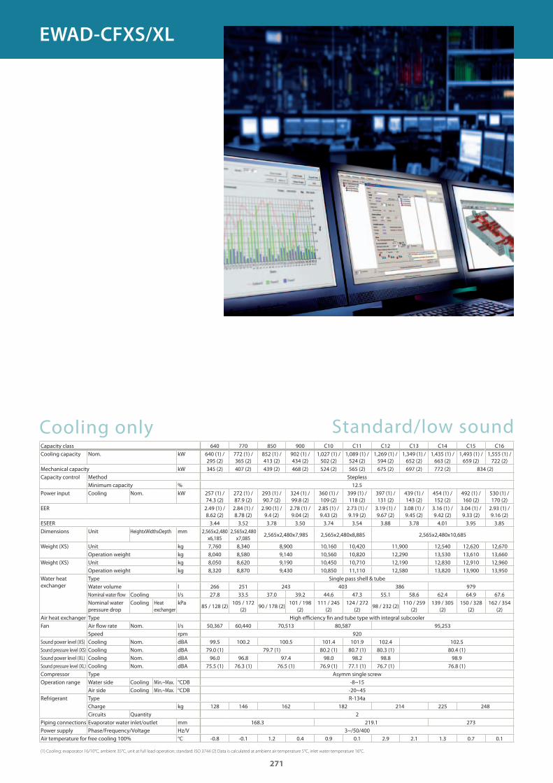
(1) Cooling: evaporator 16/10°C, ambient 35°C, unit at full load operation; standard: ISO 3744 (2) Data is calculated at ambient air temperature 5°C, inlet water temperature 16°C.
Standard/low sound640 770 850 900 C10 C11 C12 C13 C14 C15 C16
640 (1) / 295 (2)
772 (1) / 365 (2)
852 (1) / 413 (2)
902 (1) / 434 (2)
1,027 (1) / 502 (2)
1,089 (1) / 524 (2)
1,269 (1) / 594 (2)
1,349 (1) / 652 (2)
1,435 (1) / 663 (2)
1,493 (1) / 659 (2)
1,555 (1) / 722 (2)
345 (2) 407 (2) 439 (2) 468 (2) 524 (2) 565 (2) 675 (2) 697 (2) 772 (2) 834 (2)
12.5257 (1) / 74.3 (2)
272 (1) / 87.9 (2)
293 (1) / 90.7 (2)
324 (1) / 99.8 (2)
360 (1) / 109 (2)
399 (1) / 118 (2)
397 (1) / 131 (2)
439 (1) / 143 (2)
454 (1) / 152 (2)
492 (1) / 160 (2)
530 (1) / 170 (2)
2.49 (1) / 8.62 (2)
2.84 (1) / 8.78 (2)
2.90 (1) / 9.4 (2)
2.78 (1) / 9.04 (2)
2.85 (1) / 9.43 (2)
2.73 (1) / 9.19 (2)
3.19 (1) / 9.67 (2)
3.08 (1) / 9.45 (2)
3.16 (1) / 9.42 (2)
3.04 (1) / 9.33 (2)
2.93 (1) / 9.16 (2)
3.44 3.52 3.78 3.50 3.74 3.54 3.88 3.78 4.01 3.95 3.852,565x2,480
x6,1852,565x2,480
x7,0852,565x2,480x7,985 2,565x2,480x8,885 2,565x2,480x10,685
7,760 8,340 8,900 10,160 10,420 11,900 12,540 12,620 12,6708,040 8,580 9,140 10,560 10,820 12,290 13,530 13,610 13,6608,050 8,620 9,190 10,450 10,710 12,190 12,830 12,910 12,9608,320 8,870 9,430 10,850 11,110 12,580 13,820 13,900 13,950
266 251 243 403 386 97927.8 33.5 37.0 39.2 44.6 47.3 55.1 58.6 62.4 64.9 67.6
85 / 128 (2)105 / 172
(2)90 / 178 (2)
101 / 198 (2)
111 / 245 (2)
124 / 272 (2)
98 / 232 (2)110 / 259
(2)139 / 305
(2)150 / 328
(2)162 / 354
(2)
50,367 60,440 70,513 80,587 95,253920
99.5 100.2 100.5 101.4 101.9 102.4 102.579.0 (1) 79.7 (1) 80.2 (1) 80.7 (1) 80.3 (1) 80.4 (1)96.0 96.8 97.4 98.0 98.2 98.8 98.9
75.5 (1) 76.3 (1) 76.5 (1) 76.9 (1) 77.1 (1) 76.7 (1) 76.8 (1)
-8~15-20~45
128 146 162 182 214 225 2482
168.3 219.1 2733~/50/400
-0.8 -0.1 1.2 0.4 0.9 0.1 2.9 2.1 1.3 0.7 0.1
271
EWAD-CFXS/XL
GC_pre2_lowres.pdf 271 30/11/2011 12:31:50
272
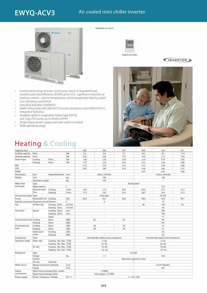
Air cooled mini chiller inverter
› Inverter technology ensures: continuous match of requested load,
excellent part load efficiency (ESEER up to 4.57), significant reduction of
starting currents ; precise temperature control (evaporator leaving water)
› Low operating sound level
› Easy ‘plug and play’ installation
› Daikin swing (sizes 005-006-007) or scroll compressor (sizes 009-010-011)
› Integrated hydronics
› Available options: evaporator heater type (OP10)
and high ESP pump up to 90 kPa (OPHP)
› Single phase power supply and main switch included
› Wide operating range
Heating & CoolingCapacity class 005 006 007 009 010 011Cooling capacity Nom. kWHeating capacity Nom. kWPower input Cooling Nom. kW
Heating Nom. kWEERCOPESEERDimensions Unit HeightxWidthxDepth mmWeight Unit kg
Operation weight kgWater heat exchanger
Type Brazed plateWater volume lNominal water flow
Cooling l/minHeating l/min
Air heat exchanger Type Tube type Hi-XSS Pump Nominal ESP unit Cooling kPaHydraulic components Expansion vessel Volume lFan Air flow rate Cooling Nom. m³/min
Heating Nom. m³/minFan motor Speed Cooling Nom. rpm
Heating Nom. rpmSteps
Sound power level Cooling Nom. dBAHeating Nom. dBA
Sound pressure level
Cooling Nom. dBAHeating Nom. dBANight quiet mode
Cooling dBAHeating dBA
Compressor Type Hermetically sealed swing compressor Hermetically sealed scroll compressorOperation range Water side Cooling Min.~Max. °CDB
Heating Min.~Max. °CDBAir side Cooling Min.~Max. °CDB
Heating Min.~Max. °CDBRefrigerant Type R-410A
Charge kgControl Electronic expansion valveCircuits Quantity
Water circuit Piping connections diameter inch G 5/4" (female)Piping inch
Piping connections
Water heat exchanger inlet / outletWater heat exchanger drain Hose nipple 1/2" FBSP
Power supply Phase / Frequency / Voltage Hz / V
Digital controller
272
5.2 6.0 7.1 8.5 9.5 11.0 5.65 6.35 7.75 10.0 11.5 13.01.89 2.35 2.95 2.74 3.19 3.821.97 2.24 2.83 2.91 3.38 3.862.75 2.55 2.41 4.37 2.98 2.882.87 2.83 2.74 3.44 3.40 3.37
- 4.57 4.52 4.46805x1,190x360 1,435x1,418x382
100 180104 -
- 1.0114.9 17.2 20.4 24.4 27.2 31.5 17.5 19.5 23.5 28.7 33.0 37.3
49.4 45.1 38.3 58.0 54.6 49.16 10- 96 100 97- 90- 780- 760- 8
62 63 64 - 64
48 50 51 48 49 51
- 45- 42
5~20 5~2225~50 25~50 10~43 10~46-15~25 -15~35
1.7 2.95
1-- 5/4"
1" MBSP --
1~ / 50 / 230
272
EWYQ-ACV3
EWYQ005-011ACV3
GC_pre2_lowres.pdf 272 30/11/2011 12:31:50
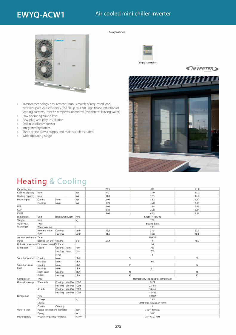
273
Heating & CoolingCapacity class 009 011 013Cooling capacity Nom. kWHeating capacity Nom. kWPower input Cooling Nom. kW
Heating Nom. kWEERCOPESEERDimensions Unit HeightxWidthxDepth mmWeight Unit kgWater heat exchanger
Type Brazed plateWater volume lNominal water flow
Cooling l/minHeating l/min
Air heat exchanger Type Hi-XSSPump Nominal ESP unit Cooling kPaHydraulic components Expansion vessel Volume lFan motor Speed Cooling Nom. rpm
Heating Nom. rpmSteps
Sound power level Cooling Nom. dBAHeating Nom. dBA
Sound pressure level
Cooling Nom. dBAHeating Nom. dBANight quiet mode
Cooling dBAHeating dBA
Compressor Type Hermetically sealed scroll compressorOperation range Water side Cooling Min.~Max. °CDB
Heating Min.~Max. °CDBAir side Cooling Min.~Max. °CDB
Heating Min.~Max. °CDBRefrigerant Type R-410A
Charge kgControl Electronic expansion valveCircuits Quantity
Water circuit Piping connections diameter inch G 5/4" (female)Piping inch
Power supply Phase / Frequency / Voltage Hz / V
Air cooled mini chiller inverter
› Inverter technology ensures: continuous match of requested load,
excellent part load efficiency (ESEER up to 4.68), significant reduction of
starting currents, precise temperature control (evaporator leaving water)
› Low operating sound level
› Easy ‘plug and play’ installation
› Daikin scroll compressor
› Integrated hydronics
› Three phase power supply and main switch included
› Wide operating range
Digital controller
273
9.0 11.0 13.211.0 12.5 14.02.96 3.82 5.10 3.23 3.70 4.19 3.04 2.88 2.59 3.41 3.38 3.34 4.68 4.63 4.52
1,435x1,418x382180
1.0125.8 31.5 37.8 31.5 35.8 40.1
56.4 49.1 40.9107807608
64 66 64
51 52 51
45 4642 43
5~2225~50 10~46-15~35
2.95
1
5/4"3N~ / 50 / 400
273
EWYQ-ACW1
EWYQ009ACW1
GC_pre2_lowres.pdf 273 30/11/2011 12:31:50
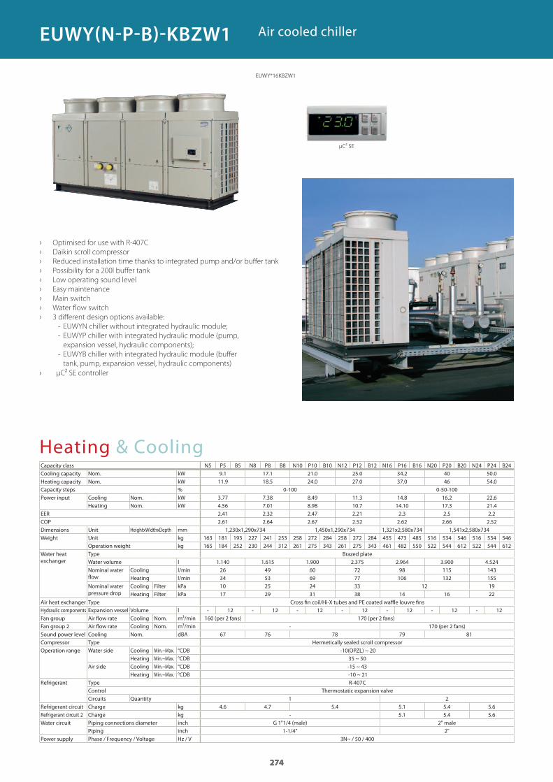
274
Heating & CoolingCapacity class N5 P5 B5 N8 P8 B8 N10 P10 B10 N12 P12 B12 N16 P16 B16 N20 P20 B20 N24 P24 B24Cooling capacity Nom. kWHeating capacity Nom. kWCapacity steps %Power input Cooling Nom. kW
Heating Nom. kWEERCOPDimensions Unit HeightxWidthxDepth mmWeight Unit kg
Operation weight kgWater heat exchanger
Type Brazed plateWater volume lNominal water flow
Cooling l/minHeating l/min
Nominal water pressure drop
Cooling Filter kPaHeating Filter kPa
Air heat exchanger Type Cross fin coil/Hi-X tubes and PE coated waffle louvre finsHydraulic components Expansion vessel Volume lFan group Air flow rate Cooling Nom. m³/min 160 (per 2 fans) 170 (per 2 fans)Fan group 2 Air flow rate Cooling Nom. m³/min 170 (per 2 fans)Sound power level Cooling Nom. dBACompressor Type Hermetically sealed scroll compressorOperation range Water side Cooling Min.~Max. °CDB
Heating Min.~Max. °CDBAir side Cooling Min.~Max. °CDB
Heating Min.~Max. °CDBRefrigerant Type R-407C
Control Thermostatic expansion valveCircuits Quantity
Refrigerant circuit Charge kgRefrigerant circuit 2 Charge kgWater circuit Piping connections diameter inch G 1"1/4 (male) 2" male
Piping inchPower supply Phase / Frequency / Voltage Hz / V
› Optimised for use with R-407C
› Daikin scroll compressor
› Reduced installation time thanks to integrated pump and/or buffer tank
› Possibility for a 200l buffer tank
› Low operating sound level
› Easy maintenance
› Main switch
› Water flow switch
› 3 different design options available:
- EUWYN chiller without integrated hydraulic module;
- EUWYP chiller with integrated hydraulic module (pump,
expansion vessel, hydraulic components);
- EUWYB chiller with integrated hydraulic module (buffer
tank, pump, expansion vessel, hydraulic components)
› μC² SE controller
Air cooled chiller
274
9.1 17.1 21.0 25.0 34.2 40 50.011.9 18.5 24.0 27.0 37.0 46 54.0
0-100 0-50-1003.77 7.38 8.49 11.3 14.8 16.2 22.64.56 7.01 8.98 10.7 14.10 17.3 21.42.41 2.32 2.47 2.21 2.3 2.5 2.22.61 2.64 2.67 2.52 2.62 2.66 2.52
1,230x1,290x734 1,450x1,290x734 1,321x2,580x734 1,541x2,580x734163 181 193 227 241 253 258 272 284 258 272 284 455 473 485 516 534 546 516 534 546165 184 252 230 244 312 261 275 343 261 275 343 461 482 550 522 544 612 522 544 612
1.140 1.615 1.900 2.375 2.964 3.900 4.52426 49 60 72 98 115 14334 53 69 77 106 132 15510 25 24 33 12 1917 29 31 38 14 16 22
- 12 - 12 - 12 - 12 - 12 - 12 - 12
-67 76 78 79 81
-10(OPZL) ~ 2035 ~ 50-15 ~ 43 -10 ~ 21
1 24.6 4.7 5.4 5.1 5.4 5.6
- 5.1 5.4 5.6
1-1/4" 2"3N~ / 50 / 400
274
EUWY*16KBZW1
EUWY(N-P-B)-KBZW1
μC² SE
GC_pre2_lowres.pdf 274 30/11/2011 12:31:51
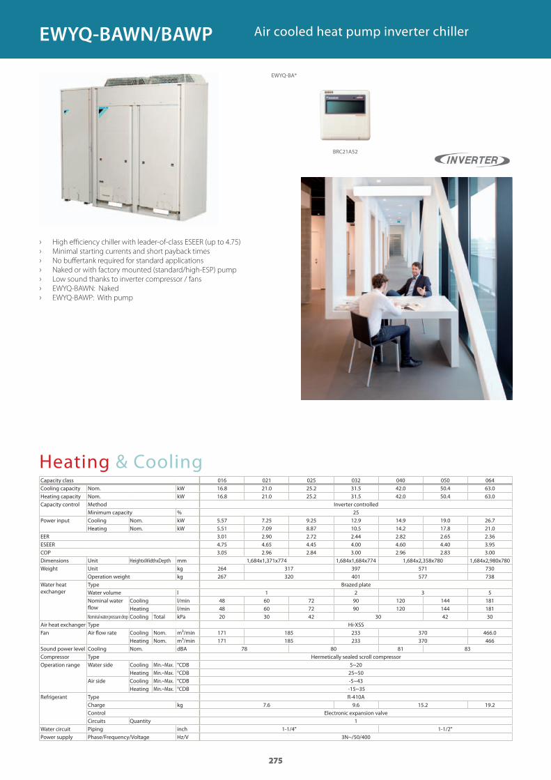
275
Heating & CoolingCapacity classCooling capacity Nom. kWHeating capacity Nom. kWCapacity control Method Inverter controlled
Minimum capacity %Power input Cooling Nom. kW
Heating Nom. kWEERESEERCOPDimensions Unit HeightxWidthxDepth mmWeight Unit kg
Operation weight kgWater heat exchanger
Type Brazed plateWater volume lNominal water flow
Cooling l/minHeating l/min
Nominal water pressure drop Cooling Total kPaAir heat exchanger Type Hi-XSSFan Air flow rate Cooling Nom. m³/min
Heating Nom. m³/minSound power level Cooling Nom. dBACompressor Type Hermetically sealed scroll compressorOperation range Water side Cooling Min.~Max. °CDB
Heating Min.~Max. °CDBAir side Cooling Min.~Max. °CDB
Heating Min.~Max. °CDBRefrigerant Type R-410A
Charge kgControl Electronic expansion valveCircuits Quantity
Water circuit Piping inchPower supply Phase/Frequency/Voltage Hz/V
Air cooled heat pump inverter chiller
› High efficiency chiller with leader-of-class ESEER (up to 4.75)
› Minimal starting currents and short payback times
› No buffertank required for standard applications
› Naked or with factory mounted (standard/high-ESP) pump
› Low sound thanks to inverter compressor / fans
› EWYQ-BAWN: Naked
› EWYQ-BAWP: With pump
275
016 021 025 032 040 050 06416.8 21.0 25.2 31.5 42.0 50.4 63.016.8 21.0 25.2 31.5 42.0 50.4 63.0
255.57 7.25 9.25 12.9 14.9 19.0 26.75.51 7.09 8.87 10.5 14.2 17.8 21.03.01 2.90 2.72 2.44 2.82 2.65 2.364.75 4.65 4.45 4.00 4.60 4.40 3.953.05 2.96 2.84 3.00 2.96 2.83 3.00
1,684x1,371x774 1,684x1,684x774 1,684x2,358x780 1,684x2,980x780264 317 397 571 730267 320 401 577 738
1 2 3 548 60 72 90 120 144 18148 60 72 90 120 144 18120 30 42 30 42 30
171 185 233 370 466.0171 185 233 370 466
78 80 81 83
5~2025~50-5~43
-15~35
7.6 9.6 15.2 19.2
11-1/4” 1-1/2"
3N~/50/400
275
EWYQ-BA*
EWYQ-BAWN/BAWP
BRC21A52
GC_pre2_lowres.pdf 275 30/11/2011 12:31:51
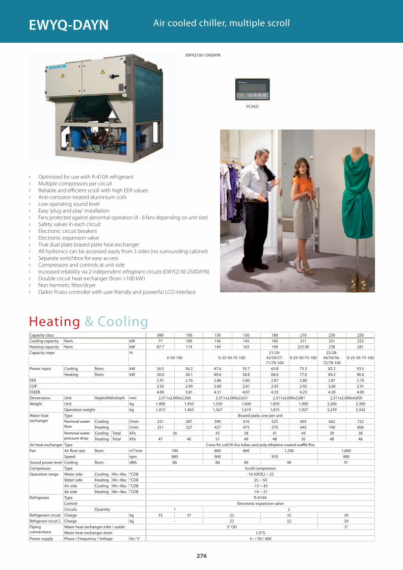
276
Heating & CoolingCapacity class 080 100 130 150 180 210 230 250Cooling capacity Nom. kWHeating capacity Nom. kWCapacity steps %
Power input Cooling Nom. kWHeating Nom. kW
EERCOPESEERDimensions Unit HeightxWidthxDepth mmWeight Unit kg
Operation weight kgWater heat exchanger
Type Brazed plate, one per unitNominal water flow
Cooling l/minHeating l/min
Nominal water pressure drop
Cooling Total kPaHeating Total kPa
Air heat exchanger Type Cross fin coil/Hi-Xss tubes and poly ethylene coated waffle finsFan Air flow rate Nom. m³/min
Speed rpmSound power level Cooling Nom. dBACompressor Type Scroll compressorOperation range Water side Cooling Min.~Max. °CDB
Water side Heating Min.~Max. °CDBAir side Cooling Min.~Max. °CDBAir side Heating Min.~Max. °CDB
Refrigerant Type R-410AControl Electronic expansion valveCircuits Quantity
Refrigerant circuit Charge kgRefrigerant circuit 2 Charge kgPiping connections
Water heat exchanger inlet / outletWater heat exchanger drain
Power supply Phase / Frequency / Voltage Hz / V
Air cooled chiller, multiple scroll
› Optimised for use with R-410A refrigerant
› Multiple compressors per circuit
› Reliable and efficient scroll with high EER values
› Anti-corrosion treated aluminium coils
› Low operating sound level
› Easy 'plug and play' installation
› Fans protected against abnormal operation (4 - 8 fans depending on unit size)
› Safety valves in each circuit
› Electronic circuit breakers
› Electronic expansion valve
› True dual plate brazed plate heat exchanger
› All hydronics can be accessed easily from 3 sides (no surrounding cabinet)
› Separate switchbox for easy access
› Compressors and controls at unit side
› Increased reliability via 2 independent refrigerant circuits (EWYQ130-250DAYN)
› Double circuit heat exchanger (from >100 kW)
› Non hermetic filter/dryer
› Daikin Pcaso controller with user friendly and powerful LCD interface
276
77 100 136 145 183 211 231 25287.7 114 149 165 199 225.00 258 281
0-50-100 0-25-50-75-10021/29-
43/50/57-71/79-100
0-25-50-75-10022/28-
44/50/56-72/78-100
0-25-50-75-100
26.5 36.2 47.6 55.7 63.8 75.3 82.2 93.530.0 38.1 49.6 58.8 68.0 77.0 84.2 96.62.91 2.76 2.86 2.60 2.87 2.80 2.81 2.702.92 2.99 3.00 2.81 2.93 2.92 3.06 2.914.00 3.81 4.31 4.07 4.33 4.23 4.20 4.002,311x2,000x2,566 2,311x2,000x2,631 2,311x2,000x3,081 2,311x2,000x4,850
1,400 1,450 1,550 1,600 1,850 1,900 3,200 3,3001,415 1,465 1,567 1,619 1,875 1,927 3,239 3,342
221 287 390 416 525 605 662 722251 327 427 473 570 645 740 806
36 43 38 41 44 39 3847 46 51 49 48 50 48 46
780 800 860 1,290 1,600880 900 970 90086 88 89 90 91
-10 (OPZL) ~ 2525 ~ 50-15 ~ 43-10 ~ 21
1 233 37 22 32 39
- 22 32 393" OD 3"
1/2"G3~ / 50 / 400
276
EWYQ-DAYN
EWYQ130-150DAYN
PCASO
GC_pre2_lowres.pdf 276 30/11/2011 12:31:51
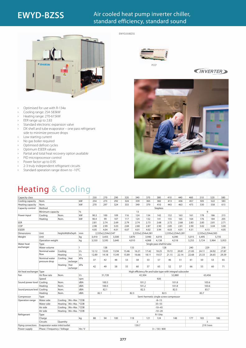
277
Heating & CoolingCapacity class 250 270 290 320 340 370 380 410 440 460 510 520 580Cooling capacity Nom. kWHeating capacity Nom. kWCapacity control Method Stepless
Minimum capacity %Power input Cooling Nom. kW
Heating Nom. kWEERCOPESEERDimensions Unit HeightxWidthxDepth mmWeight Unit kg
Operation weight kgWater heat exchanger
Type Single pass shell & tubeWater volume lNominal water fl ow
Cooling l/sHeating l/s
Nominal water pressure drop
Cooling Heat exchanger
kPa
Heating Heat exchanger
kPa
Air heat exchanger Type High effi ciency fi n and tube type with integral subcoolerFan Air fl ow rate Nom. l/s
Speed rpmSound power level Cooling Nom. dBA
Heating Nom. dBASound pressure level Cooling Nom. dBA
Heating Nom. dBACompressor Type Semi-hermetic single screw compressorOperation range Water side Cooling Min.~Max. °CDB
Water side Heating Min.~Max. °CDBAir side Cooling Min.~Max. °CDBAir side Heating Min.~Max. °CDB
Refrigerant Type R-134aCharge kgCircuits Quantity
Piping connections Evaporator water inlet/outletPower supply Phase / Frequency / Voltage Hz / V
› Optimised for use with R-134a
› Cooling range: 254-583kW
› Heating range: 270-615kW
› EER range up to 2.83
› Standard electronic expansion valve
› DX shell and tube evaporator – one pass refrigerant
side to minimize pressure drops
› Low starting current
› No gas boiler required
› Optimised defrost cycles
› Optimum ESEER values
› Partial and total heat recovery option available
› PID microprocessor control
› Power factor up to 0.95
› 2-3 truly independent refrigerant circuits
› Standard operation range down to -10°C
Air cooled heat pump inverter chiller, standard efficiency, standard sound
277
254 273 292 324 339 365 382 413 436 457 505 522 583270 297 324 333 349 379 410 443 463 475 530 558 615
13 990.3 100 109 116 124 134 142 152 163 161 178 186 21590.4 99 107 117 124 132 141 155 165 164 176 184 2052.81 2.74 2.69 2.79 2.74 2.73 2.68 2.72 2.68 2.83 2.83 2.81 2.712.98 2.99 3.03 2.84 2.80 2.87 2.90 2.85 2.81 2.90 3.02 3.04 3.004.05 4.04 4.01 4.07 4.01 4.02 3.94 4.03 4.01 4.31 4.13 4.05
2,335x2,254x3,547 2,335x2,254x4,381 2,335x2,254x5,281 2,335x2,254x6,5833,410 3,455 3,500 3,870 3,940 4,010 4,390 5,015 5,495 5,7353,550 3,595 3,640 4,010 4,068 4,138 4,518 5,255 5,724 5,964 5,953
138 133 128 240 229 21812.12 13.03 13.94 15.46 16.21 17.42 18.25 19.72 20.81 21.83 24.11 24.92 27.8712.89 14.18 15.49 15.89 16.66 18.11 19.57 21.15 22.14 22.68 25.33 26.65 29.39
37 42 48 53 58 53 57 46 51 61 50 53 65
42 49 58 55 60 57 65 52 57 66 55 60 71
31,728 42,304 52,880 63,456920
100.5 101.2 101.8 103.6100.5 101.2 101.8 103.682.1 82.3 82.5 83.7
82.1 82.3 82.5 83.7
-8~1535~55-10~45-10~20
88 94 100 118 121 124 148 177 183 1862 3
139.7 219.1mm3~ / 50 / 400
277
EWYD250BZSS
EWYD-BZSS
PCO2
GC_pre2_lowres.pdf 277 30/11/2011 12:31:52
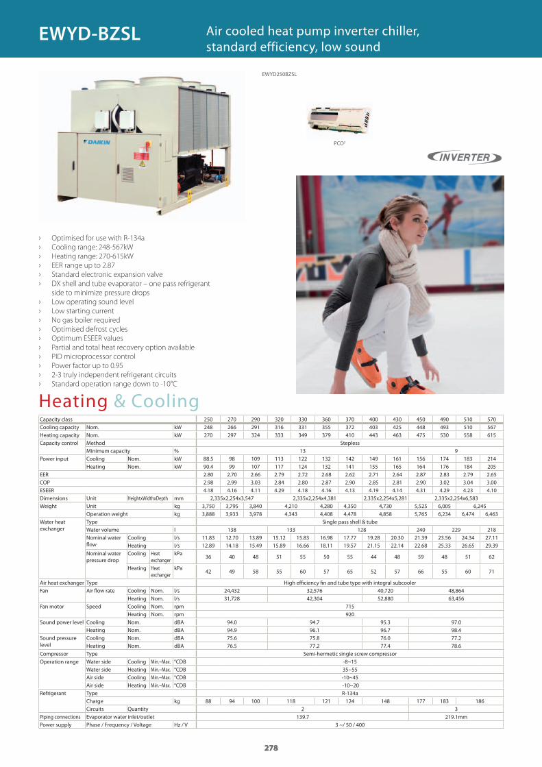
278
Heating & CoolingCapacity class 250 270 290 320 330 360 370 400 430 450 490 510 570Cooling capacity Nom. kWHeating capacity Nom. kWCapacity control Method Stepless
Minimum capacity %Power input Cooling Nom. kW
Heating Nom. kWEERCOPESEERDimensions Unit HeightxWidthxDepth mmWeight Unit kg
Operation weight kgWater heat exchanger
Type Single pass shell & tubeWater volume lNominal water flow
Cooling l/sHeating l/s
Nominal water pressure drop
Cooling Heat exchanger
kPa
Heating Heat exchanger
kPa
Air heat exchanger Type High efficiency fin and tube type with integral subcoolerFan Air flow rate Cooling Nom. l/s
Heating Nom. l/sFan motor Speed Cooling Nom. rpm
Heating Nom. rpmSound power level Cooling Nom. dBA
Heating Nom. dBASound pressure level
Cooling Nom. dBAHeating Nom. dBA
Compressor Type Semi-hermetic single screw compressorOperation range Water side Cooling Min.~Max. °CDB
Water side Heating Min.~Max. °CDBAir side Cooling Min.~Max. °CDBAir side Heating Min.~Max. °CDB
Refrigerant Type R-134aCharge kgCircuits Quantity
Piping connections Evaporator water inlet/outletPower supply Phase / Frequency / Voltage Hz / V
› Optimised for use with R-134a
› Cooling range: 248-567kW
› Heating range: 270-615kW
› EER range up to 2.87
› Standard electronic expansion valve
› DX shell and tube evaporator – one pass refrigerant
side to minimize pressure drops
› Low operating sound level
› Low starting current
› No gas boiler required
› Optimised defrost cycles
› Optimum ESEER values
› Partial and total heat recovery option available
› PID microprocessor control
› Power factor up to 0.95
› 2-3 truly independent refrigerant circuits
› Standard operation range down to -10°C
Air cooled heat pump inverter chiller, standard efficiency, low sound
278
248 266 291 316 331 355 372 403 425 448 493 510 567 270 297 324 333 349 379 410 443 463 475 530 558 615
13 988.5 98 109 113 122 132 142 149 161 156 174 183 214 90.4 99 107 117 124 132 141 155 165 164 176 184 205 2.80 2.70 2.66 2.79 2.72 2.68 2.62 2.71 2.64 2.87 2.83 2.79 2.65 2.98 2.99 3.03 2.84 2.80 2.87 2.90 2.85 2.81 2.90 3.02 3.04 3.004.18 4.16 4.11 4.29 4.18 4.16 4.13 4.19 4.14 4.31 4.29 4.23 4.10
2,335x2,254x3,547 2,335x2,254x4,381 2,335x2,254x5,281 2,335x2,254x6,5833,750 3,795 3,840 4,210 4,280 4,350 4,730 5,525 6,005 6,2453,888 3,933 3,978 4,343 4,408 4,478 4,858 5,765 6,234 6,474 6,463
138 133 128 240 229 21811.83 12.70 13.89 15.12 15.83 16.98 17.77 19.28 20.30 21.39 23.56 24.34 27.1112.89 14.18 15.49 15.89 16.66 18.11 19.57 21.15 22.14 22.68 25.33 26.65 29.39
36 40 48 51 55 50 55 44 48 59 48 51 62
42 49 58 55 60 57 65 52 57 66 55 60 71
24,432 32,576 40,720 48,86431,728 42,304 52,880 63,456
715920
94.0 94.7 95.3 97.094.9 96.1 96.7 98.475.6 75.8 76.0 77.276.5 77.2 77.4 78.6
-8~1535~55-10~45 -10~20
88 94 100 118 121 124 148 177 183 1862 3
139.7 219.1mm3 ~/ 50 / 400
278
EWYD250BZSL
EWYD-BZSL
PCO2
GC_pre2_lowres.pdf 278 30/11/2011 12:31:52
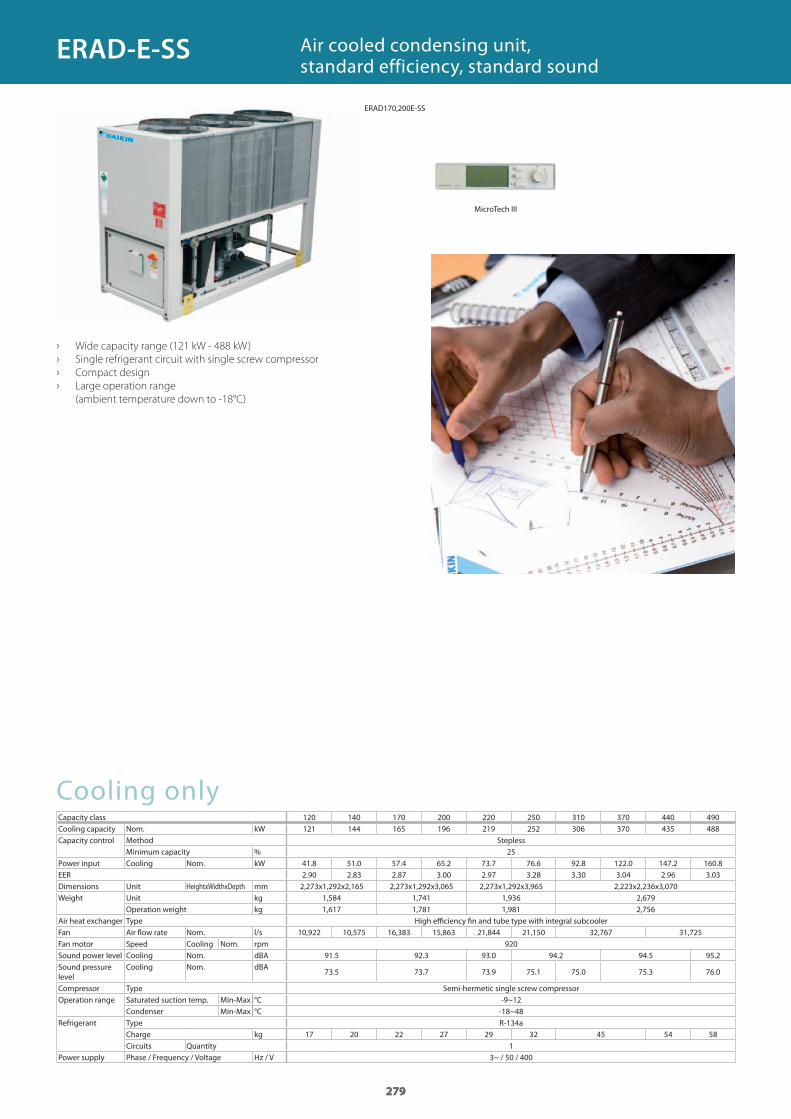
279
Cooling onlyCapacity class 120 140 170 200 220 250 310 370 440 490Cooling capacity Nom. kWCapacity control Method Stepless
Minimum capacity %Power input Cooling Nom. kWEERDimensions Unit HeightxWidthxDepth mmWeight Unit kg
Operation weight kgAir heat exchanger Type High effi ciency fi n and tube type with integral subcoolerFan Air fl ow rate Nom. l/sFan motor Speed Cooling Nom. rpmSound power level Cooling Nom. dBASound pressure level
Cooling Nom. dBA
Compressor Type Semi-hermetic single screw compressorOperation range Saturated suction temp. Min-Max °C
Condenser Min-Max °CRefrigerant Type R-134a
Charge kgCircuits Quantity
Power supply Phase / Frequency / Voltage Hz / V
Air cooled condensing unit,standard efficiency, standard sound
› Wide capacity range (121 kW - 488 kW)
› Single refrigerant circuit with single screw compressor
› Compact design
› Large operation range
(ambient temperature down to -18°C)
279
121 144 165 196 219 252 306 370 435 488
2541.8 51.0 57.4 65.2 73.7 76.6 92.8 122.0 147.2 160.8 2.90 2.83 2.87 3.00 2.97 3.28 3.30 3.04 2.96 3.03 2,273x1,292x2,165 2,273x1,292x3,065 2,273x1,292x3,965 2,223x2,236x3,070
1,584 1,741 1,936 2,6791,617 1,781 1,981 2,756
10,922 10,575 16,383 15,863 21,844 21,150 32,767 31,725920
91.5 92.3 93.0 94.2 94.5 95.2
73.5 73.7 73.9 75.1 75.0 75.3 76.0
-9~12-18~48
17 20 22 27 29 32 45 54 581
3~ / 50 / 400
279
ERAD-E-SS
ERAD170,200E-SS
MicroTech III
GC_pre2_lowres.pdf 279 30/11/2011 12:31:52
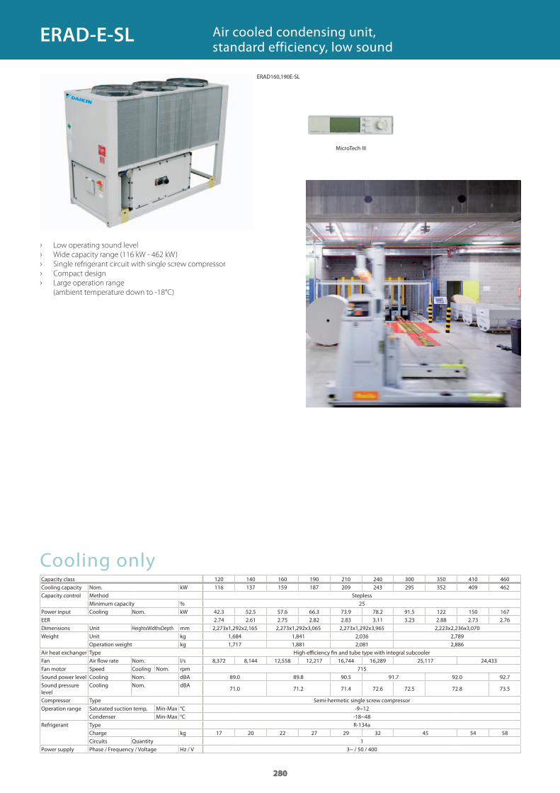
280
Cooling onlyCapacity class 120 140 160 190 210 240 300 350 410 460Cooling capacity Nom. kWCapacity control Method Stepless
Minimum capacity %Power input Cooling Nom. kWEERDimensions Unit HeightxWidthxDepth mmWeight Unit kg
Operation weight kgAir heat exchanger Type High effi ciency fi n and tube type with integral subcoolerFan Air fl ow rate Nom. l/sFan motor Speed Cooling Nom. rpmSound power level Cooling Nom. dBASound pressure level
Cooling Nom. dBA
Compressor Type Semi-hermetic single screw compressorOperation range Saturated suction temp. Min-Max °C
Condenser Min-Max °CRefrigerant Type R-134a
Charge kgCircuits Quantity
Power supply Phase / Frequency / Voltage Hz / V
Air cooled condensing unit,standard efficiency, low sound
› Low operating sound level
› Wide capacity range (116 kW - 462 kW)
› Single refrigerant circuit with single screw compressor
› Compact design
› Large operation range
(ambient temperature down to -18°C)
280
116 137 159 187 209 243 295 352 409 462
2542.3 52.5 57.6 66.3 73.9 78.2 91.5 122 150 167 2.74 2.61 2.75 2.82 2.83 3.11 3.23 2.88 2.73 2.76 2,273x1,292x2,165 2,273x1,292x3,065 2,273x1,292x3,965 2,223x2,236x3,070
1,684 1,841 2,036 2,7891,717 1,881 2,081 2,886
8,372 8,144 12,558 12,217 16,744 16,289 25,117 24,433715
89.0 89.8 90.5 91.7 92.0 92.7
71.0 71.2 71.4 72.6 72.5 72.8 73.5
-9~12-18~48
17 20 22 27 29 32 45 54 581
3~ / 50 / 400
280
ERAD-E-SL
ERAD160,190E-SL
MicroTech III
GC_pre2_lowres.pdf 280 30/11/2011 12:31:53
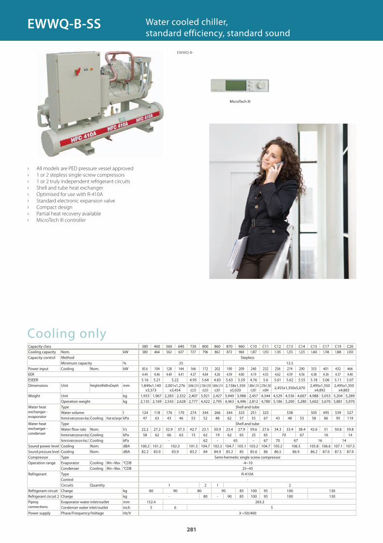
281
Cooling onlyCapacity classCooling capacity Nom. kWCapacity control Method Stepless
Minimum capacity %Power input Cooling Nom. kWEERESEERDimensions Unit HeightxWidthxDepth mm
Weight Unit kgOperation weight kg
Water heat exchanger - evaporator
Type Shell and tubeWater volume lNominal water pressure drop Cooling Heat exchanger kPa
Water heat exchanger - condenser
Type Shell and tubeWater flow rate Nom. l/sNominal water pressure drop Cooling kPaNominal water pressure drop 2 Cooling kPa
Sound power level Cooling Nom. dBASound pressure level Cooling Nom. dBACompressor Type Semi-hermetic single screw compressorOperation range Evaporator Cooling Min.~Max. °CDB
Condenser Cooling Min.~Max. °CDBRefrigerant Type R-410A
ControlCircuits Quantity
Refrigerant circuit Charge kgRefrigerant circuit 2 Charge kgPiping connections
Evaporator water inlet/outlet mmCondenser water inlet/outlet inch
Power supply Phase/Frequency/Voltage Hz/V
› All models are PED pressure vessel approved
› 1 or 2 stepless single-screw compressors
› 1 or 2 truly independent refrigerant circuits
› Shell and tube heat exchanger
› Optimised for use with R-410A
› Standard electronic expansion valve
› Compact design
› Partial heat recovery available
› MicroTech III controller
Water cooled chiller, standard efficiency, standard sound
281
380 460 560 640 730 800 860 870 960 C10 C11 C12 C13 C14 C15 C17 C19 C20380 464 562 637 727 796 862 872 960 1,007 1,055 1,185 1,255 1,325 1,460 1,748 1,888 2,050
25 12.585.6 104 128 144 166 172 202 190 209 240 232 256 274 290 333 401 432 466 4.44 4.46 4.40 4.41 4.37 4.64 4.26 4.59 4.60 4.19 4.55 4.62 4.59 4.56 4.38 4.36 4.37 4.40 5.16 5.21 5.22 4.95 5.64 4.83 5.63 5.59 4.76 5.6 5.61 5.62 5.55 5.18 5.06 5.11 5.07
1,849x1,140 x3,373
2,001x1,276 x3,454
1,848x1,314 x3,535
2,158x1,350 x5,020
1,848x1,314 x2,001
2,158x1,350 x5,020
1,848x1,314 x2,001
2,378x1,350 x4,894 2,455x1,350x5,070 2,495x1,350
x4,8922,495x1,350
x4,865
1,933 1,967 2,283 2,332 2,407 3,921 2,427 3,949 3,988 2,457 4,344 4,529 4,536 4,607 4,988 5,053 5,204 5,2892,135 2,169 2,543 2,628 2,777 4,422 2,795 4,463 4,496 2,812 4,780 5,186 5,200 5,280 5,602 5,670 5,881 5,970
124 118 176 170 274 344 266 344 325 251 325 538 505 495 539 52747 63 43 46 53 52 48 62 57 55 67 43 48 53 58 86 95 119
22.2 27.2 32.9 37.3 42.7 23.1 50.9 23.4 27.9 59.6 27.6 34.3 33.4 38.4 42.6 51 50.8 59.858 62 66 63 15 62 19 62 65 25 65 70 67 16 14
- 62 - 65 - 67 70 67 16 14100.2 101.2 102.3 101.5 104.7 102.3 104.7 105.1 103.2 104.7 105.2 106.5 105.8 106.6 107.1 107.582.2 83.0 83.9 83.2 84 84.9 85.2 85 85.6 86 86.5 86.9 86.2 87.0 87.5 87.9
-4~1025~45
-1 2 1 2
80 90 80 90 85 100 95 100 130- 80 - 90 85 100 95 100 130
152.4 203.25 6 5
3~/50/400
281
EWWQ-B-
EWWQ-B-SS
MicroTech III
GC_pre2_lowres.pdf 281 30/11/2011 12:31:53
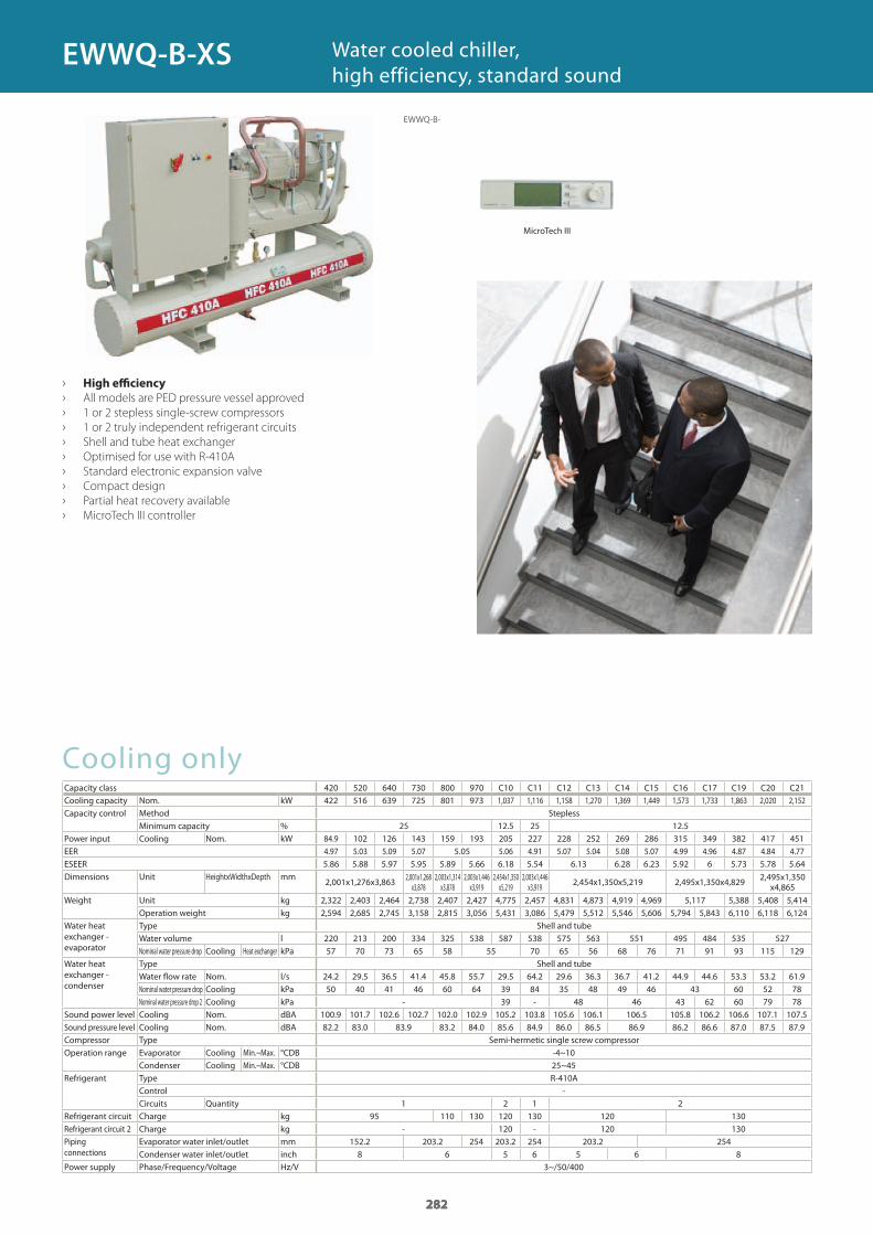
282
Cooling onlyCapacity classCooling capacity Nom. kWCapacity control Method Stepless
Minimum capacity %Power input Cooling Nom. kWEERESEERDimensions Unit HeightxWidthxDepth mm
Weight Unit kgOperation weight kg
Water heat exchanger - evaporator
Type Shell and tubeWater volume lNominal water pressure drop Cooling Heat exchanger kPa
Water heat exchanger - condenser
Type Shell and tubeWater flow rate Nom. l/sNominal water pressure drop Cooling kPaNominal water pressure drop 2 Cooling kPa
Sound power level Cooling Nom. dBASound pressure level Cooling Nom. dBACompressor Type Semi-hermetic single screw compressorOperation range Evaporator Cooling Min.~Max. °CDB
Condenser Cooling Min.~Max. °CDBRefrigerant Type R-410A
ControlCircuits Quantity
Refrigerant circuit Charge kgRefrigerant circuit 2 Charge kgPiping connections
Evaporator water inlet/outlet mmCondenser water inlet/outlet inch
Power supply Phase/Frequency/Voltage Hz/V
› High efficiency
› All models are PED pressure vessel approved
› 1 or 2 stepless single-screw compressors
› 1 or 2 truly independent refrigerant circuits
› Shell and tube heat exchanger
› Optimised for use with R-410A
› Standard electronic expansion valve
› Compact design
› Partial heat recovery available
› MicroTech III controller
Water cooled chiller, high efficiency, standard sound
282
420 520 640 730 800 970 C10 C11 C12 C13 C14 C15 C16 C17 C19 C20 C21422 516 639 725 801 973 1,037 1,116 1,158 1,270 1,369 1,449 1,573 1,733 1,863 2,020 2,152
25 12.5 25 12.584.9 102 126 143 159 193 205 227 228 252 269 286 315 349 382 417 451 4.97 5.03 5.09 5.07 5.05 5.06 4.91 5.07 5.04 5.08 5.07 4.99 4.96 4.87 4.84 4.77 5.86 5.88 5.97 5.95 5.89 5.66 6.18 5.54 6.13 6.28 6.23 5.92 6 5.73 5.78 5.64
2,001x1,276x3,863 2,001x1,268 x3,878
2,003x1,314 x3,878
2,003x1,446 x3,919
2,454x1,350 x5,219
2,003x1,446 x3,919 2,454x1,350x5,219 2,495x1,350x4,829 2,495x1,350
x4,865
2,322 2,403 2,464 2,738 2,407 2,427 4,775 2,457 4,831 4,873 4,919 4,969 5,117 5,388 5,408 5,4142,594 2,685 2,745 3,158 2,815 3,056 5,431 3,086 5,479 5,512 5,546 5,606 5,794 5,843 6,110 6,118 6,124
220 213 200 334 325 538 587 538 575 563 551 495 484 535 52757 70 73 65 58 55 70 65 56 68 76 71 91 93 115 129
24.2 29.5 36.5 41.4 45.8 55.7 29.5 64.2 29.6 36.3 36.7 41.2 44.9 44.6 53.3 53.2 61.950 40 41 46 60 64 39 84 35 48 49 46 43 60 52 78
- 39 - 48 46 43 62 60 79 78100.9 101.7 102.6 102.7 102.0 102.9 105.2 103.8 105.6 106.1 106.5 105.8 106.2 106.6 107.1 107.582.2 83.0 83.9 83.2 84.0 85.6 84.9 86.0 86.5 86.9 86.2 86.6 87.0 87.5 87.9
-4~1025~45
-1 2 1 2
95 110 130 120 130 120 130- 120 - 120 130
152.2 203.2 254 203.2 254 203.2 2548 6 5 6 5 6 8
3~/50/400
282
EWWQ-B-
EWWQ-B-XS
MicroTech III
GC_pre2_lowres.pdf 282 30/11/2011 12:31:53
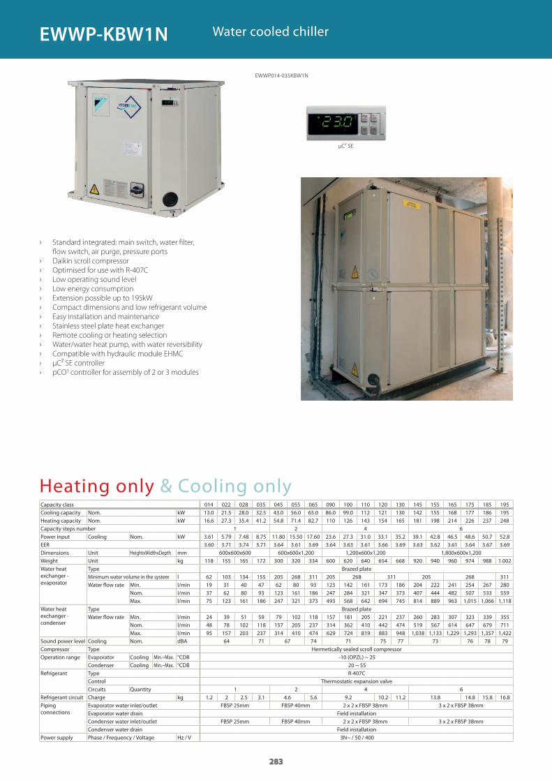
283
Heating only & Cooling onlyCapacity class 014 022 028 035 045 055 065 090 100 110 120 130 145 155 165 175 185 195Cooling capacity Nom. kWHeating capacity Nom. kWCapacity steps numberPower input Cooling Nom. kWEERDimensions Unit HeightxWidthxDepth mmWeight Unit kgWater heat exchanger - evaporator
Type Brazed plateMinimum water volume in the system lWater fl ow rate Min. l/min
Nom. l/minMax. l/min
Water heat exchanger - condenser
Type Brazed plateWater fl ow rate Min. l/min
Nom. l/minMax. l/min
Sound power level Cooling Nom. dBACompressor Type Hermetically sealed scroll compressorOperation range Evaporator Cooling Min.~Max. °CDB
Condenser Cooling Min.~Max. °CDBRefrigerant Type R-407C
Control Thermostatic expansion valveCircuits Quantity
Refrigerant circuit Charge kgPiping connections
Evaporator water inlet/outlet FBSP 25mm FBSP 40mm 2 x 2 x FBSP 38mm 3 x 2 x FBSP 38mmEvaporator water drain Field installationCondenser water inlet/outlet FBSP 25mm FBSP 40mm 2 x 2 x FBSP 38mm 3 x 2 x FBSP 38mmCondenser water drain Field installation
Power supply Phase / Frequency / Voltage Hz / V
› Standard integrated: main switch, water fi lter,
fl ow switch, air purge, pressure ports
› Daikin scroll compressor
› Optimised for use with R-407C
› Low operating sound level
› Low energy consumption
› Extension possible up to 195kW
› Compact dimensions and low refrigerant volume
› Easy installation and maintenance
› Stainless steel plate heat exchanger
› Remote cooling or heating selection
› Water/water heat pump, with water reversibility
› Compatible with hydraulic module EHMC
› μC² SE controller
› pCO3 controller for assembly of 2 or 3 modules
Water cooled chiller
283
13.0 21.5 28.0 32.5 43.0 56.0 65.0 86.0 99.0 112 121 130 142 155 168 177 186 195 16.6 27.3 35.4 41.2 54.8 71.4 82.7 110 126 143 154 165 181 198 214 226 237 248
1 2 4 63.61 5.79 7.48 8.75 11.80 15.50 17.60 23.6 27.3 31.0 33.1 35.2 39.1 42.8 46.5 48.6 50.7 52.83.60 3.71 3.74 3.71 3.64 3.61 3.69 3.64 3.63 3.61 3.66 3.69 3.63 3.62 3.61 3.64 3.67 3.69
600x600x600 600x600x1,200 1,200x600x1,200 1,800x600x1,200118 155 165 172 300 320 334 600 620 640 654 668 920 940 960 974 988 1.002
62 103 134 155 205 268 311 205 268 311 205 268 31119 31 40 47 62 80 93 123 142 161 173 186 204 222 241 254 267 28037 62 80 93 123 161 186 247 284 321 347 373 407 444 482 507 533 55975 123 161 186 247 321 373 493 568 642 694 745 814 889 963 1,015 1,066 1,118
24 39 51 59 79 102 118 157 181 205 221 237 260 283 307 323 339 35548 78 102 118 157 205 237 314 362 410 442 474 519 567 614 647 679 71195 157 203 237 314 410 474 629 724 819 883 948 1,038 1,133 1,229 1,293 1,357 1,422
64 71 67 74 71 75 77 73 76 78 79
-10 (OPZL) ~ 2520 ~ 55
1 2 4 61.2 2 2.5 3.1 4.6 5.6 9.2 10.2 11.2 13.8 14.8 15.8 16.8
3N~ / 50 / 400
283
EWWP014-035KBW1N
EWWP-KBW1N
μC² SE
GC_pre2_lowres.pdf 283 30/11/2011 12:31:54
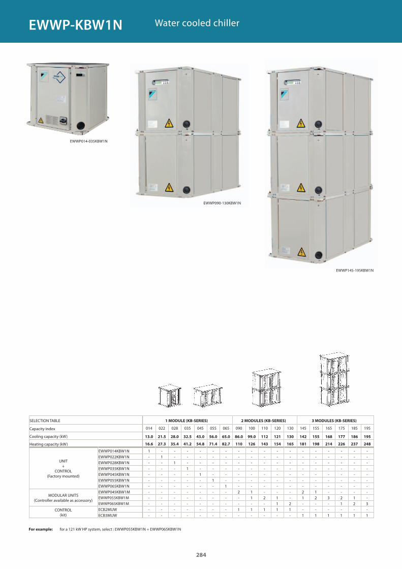
SELECTION TABLE 1 MODULE (KB-SERIES) 2 MODULES (KB-SERIES) 3 MODULES (KB-SERIES)
Capacity index
Cooling capacity (kW)
Heating capacity (kW)
UNIT+
CONTROL(Factory mounted)
EWWP014KBW1NEWWP022KBW1NEWWP028KBW1NEWWP035KBW1NEWWP045KBW1NEWWP055KBW1NEWWP065KBW1N
MODULAR UNITS(Controller available as accessory)
EWWP045KBW1MEWWP055KBW1M
EWWP065KBW1M
CONTROL(kit)
ECB2MUWECB3MUW
For example: for a 121 kW HP system, select : EWWP055KBW1N + EWWP065KBW1N
Water cooled chiller
014 022 028 035 045 055 065 090 100 110 120 130 145 155 165 175 185 195
13.0 21.5 28.0 32.5 43.0 56.0 65.0 86.0 99.0 112 121 130 142 155 168 177 186 195
16.6 27.3 35.4 41.2 54.8 71.4 82.7 110 126 143 154 165 181 198 214 226 237 248
1 - - - - - - - - - - - - - - - - -- 1 - - - - - - - - - - - - - - - -- - 1 - - - - - - - - - - - - - - -- - - 1 - - - - - - - - - - - - - -- - - - 1 - - - - - - - - - - - - -- - - - - 1 - - - - - - - - - - - -- - - - - - 1 - - - - - - - - - - -- - - - - - - 2 1 - - - 2 1 - - - -- - - - - - - - 1 2 1 - 1 2 3 2 1 -- - - - - - - - - - 1 2 - - - 1 2 3- - - - - - - 1 1 1 1 1 - - - - - -- - - - - - - - - - - - 1 1 1 1 1 1
EWWP014-035KBW1N
EWWP090-130KBW1N
EWWP145-195KBW1N
284
EWWP-KBW1N
GC_pre2_lowres.pdf 284 30/11/2011 12:31:54
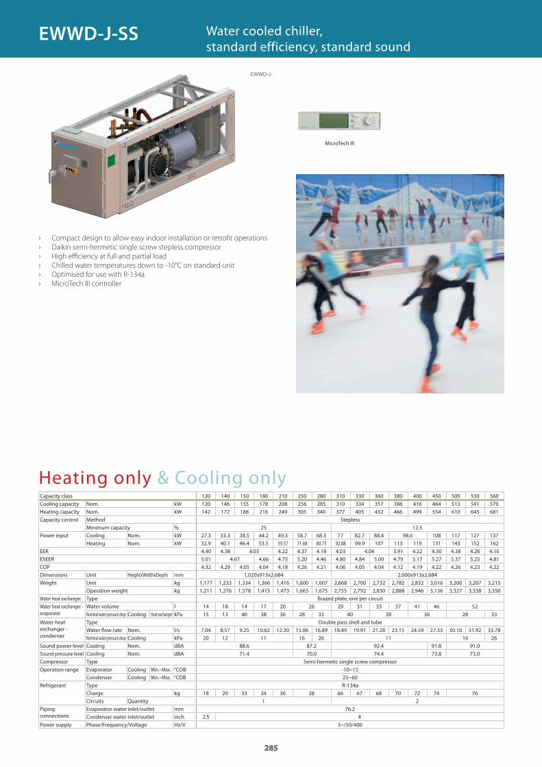
285
Heating only & Cooling onlyCapacity classCooling capacity Nom. kWHeating capacity Nom. kWCapacity control Method Stepless
Minimum capacity %Power input Cooling Nom. kW
Heating Nom. kWEERESEERCOPDimensions Unit HeightxWidthxDepth mmWeight Unit kg
Operation weight kgWater heat exchanger Type Brazed plate, one per circuitWater heat exchanger - evaporator
Water volume lNominal water pressure drop Cooling Heat exchanger kPa
Water heat exchanger - condenser
Type Double pass shell and tubeWater flow rate Nom. l/sNominal water pressure drop Cooling kPa
Sound power level Cooling Nom. dBASound pressure level Cooling Nom. dBACompressor Type Semi-hermetic single screw compressorOperation range Evaporator Cooling Min.~Max. °CDB
Condenser Cooling Min.~Max. °CDBRefrigerant Type R-134a
Charge kgCircuits Quantity
Piping connections
Evaporator water inlet/outlet mmCondenser water inlet/outlet inch
Power supply Phase/Frequency/Voltage Hz/V
› Compact design to allow easy indoor installation or retrofit operations
› Daikin semi-hermetic single screw stepless compressor
› High efficiency at full and partial load
› Chilled water temperatures down to -10°C on standard unit
› Optimised for use with R-134a
› MicroTech III controller
Water cooled chiller, standard efficiency, standard sound
285
120 140 150 180 210 250 280 310 330 360 380 400 450 500 530 560120 146 155 178 208 256 285 310 334 357 386 416 464 513 541 570 142 172 188 216 249 305 340 377 405 432 466 499 554 610 645 681
25 12.527.3 33.3 38.5 44.2 49.3 58.7 68.3 77 82.7 88.4 98.6 108 117 127 137 32.9 40.1 46.4 53.5 59.57 71.68 80.75 92.88 99.9 107 113 119 131 143 152 162 4.40 4.38 4.03 4.22 4.37 4.18 4.03 4.04 3.91 4.22 4.30 4.38 4.26 4.16 5.01 4.67 4.66 4.75 5.20 4.46 4.80 4.84 5.00 4.79 5.17 5.27 5.37 5.25 4.814.32 4.29 4.05 4.04 4.18 4.26 4.21 4.06 4.05 4.04 4.12 4.19 4.22 4.26 4.23 4.22
1,020x913x2,684 2,000x913x2,6841,177 1,233 1,334 1,366 1,416 1,600 1,607 2,668 2,700 2,732 2,782 2,832 3,016 3,200 3,207 3,2151,211 1,276 1,378 1,415 1,473 1,663 1,675 2,755 2,792 2,830 2,888 2,946 3,136 3,327 3,338 3,350
14 18 14 17 20 26 29 31 33 37 41 46 5215 13 40 38 36 28 33 40 38 36 28 33
7.04 8.57 9.25 10.62 12.30 15.06 16.89 18.49 19.91 21.28 23.15 24.59 27.33 30.10 31.92 33.7820 12 11 16 26 11 16 26
88.6 87.2 92.4 91.8 91.0 71.4 70.0 74.4 73.8 73.0
-10~1523~60
18 20 33 34 36 38 66 67 68 70 72 74 761 2
76.22.5 4
3~/50/400
285
EWWD-J-
EWWD-J-SS
MicroTech III
GC_pre2_lowres.pdf 285 30/11/2011 12:31:54
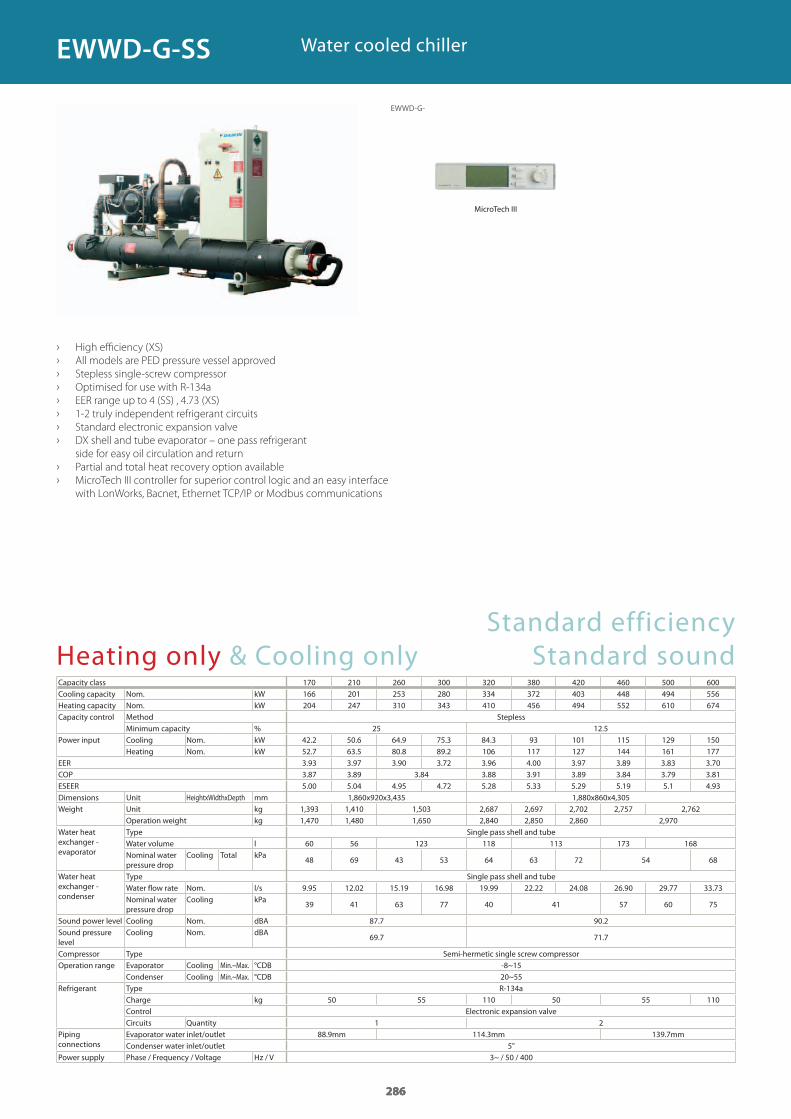
286
Heating only & Cooling onlyCapacity class 170 210 260 300 320 380 420 460 500 600Cooling capacity Nom. kWHeating capacity Nom. kWCapacity control Method Stepless
Minimum capacity %Power input Cooling Nom. kW
Heating Nom. kWEERCOPESEERDimensions Unit HeightxWidthxDepth mmWeight Unit kg
Operation weight kgWater heat exchanger - evaporator
Type Single pass shell and tubeWater volume lNominal water pressure drop
Cooling Total kPa
Water heat exchanger - condenser
Type Single pass shell and tubeWater flow rate Nom. l/sNominal water pressure drop
Cooling kPa
Sound power level Cooling Nom. dBASound pressure level
Cooling Nom. dBA
Compressor Type Semi-hermetic single screw compressorOperation range Evaporator Cooling Min.~Max. °CDB
Condenser Cooling Min.~Max. °CDBRefrigerant Type R-134a
Charge kgControl Electronic expansion valveCircuits Quantity
Piping connections
Evaporator water inlet/outlet 88.9mm 114.3mm 139.7mmCondenser water inlet/outlet
Power supply Phase / Frequency / Voltage Hz / V
› High efficiency (XS)
› All models are PED pressure vessel approved
› Stepless single-screw compressor
› Optimised for use with R-134a
› EER range up to 4 (SS) , 4.73 (XS)
› 1-2 truly independent refrigerant circuits
› Standard electronic expansion valve
› DX shell and tube evaporator – one pass refrigerant
side for easy oil circulation and return
› Partial and total heat recovery option available
› MicroTech III controller for superior control logic and an easy interface
with LonWorks, Bacnet, Ethernet TCP/IP or Modbus communications
Water cooled chiller
Standard efficiency Standard sound
286
166 201 253 280 334 372 403 448 494 556 204 247 310 343 410 456 494 552 610 674
25 12.542.2 50.6 64.9 75.3 84.3 93 101 115 129 150 52.7 63.5 80.8 89.2 106 117 127 144 161 177 3.93 3.97 3.90 3.72 3.96 4.00 3.97 3.89 3.83 3.70 3.87 3.89 3.84 3.88 3.91 3.89 3.84 3.79 3.81 5.00 5.04 4.95 4.72 5.28 5.33 5.29 5.19 5.1 4.93
1,860x920x3,435 1,880x860x4,3051,393 1,410 1,503 2,687 2,697 2,702 2,757 2,7621,470 1,480 1,650 2,840 2,850 2,860 2,970
60 56 123 118 113 173 168
48 69 43 53 64 63 72 54 68
9.95 12.02 15.19 16.98 19.99 22.22 24.08 26.90 29.77 33.73
39 41 63 77 40 41 57 60 75
87.7 90.2
69.7 71.7
-8~1520~55
50 55 110 50 55 110
1 2
5"3~ / 50 / 400
286
EWWD-G-
EWWD-G-SS
MicroTech III
GC_pre2_lowres.pdf 286 30/11/2011 12:31:55
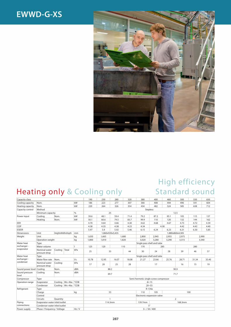
287
Heating only & Cooling onlyCapacity class 190 230 280 320 380 400 460 500 550 650Cooling capacity Nom. kWHeating capacity Nom. kWCapacity control Method Stepless
Minimum capacity %Power input Cooling Nom. kW
Heating Nom. kWEERCOPESEERDimensions Unit HeightxWidthxDepth mmWeight Unit kg
Operation weight kgWater heat exchanger - evaporator
Type Single pass shell and tubeWater volume lNominal water pressure drop
Cooling Total kPa
Water heat exchanger - condenser
Type Single pass shell and tubeWater fl ow rate Nom. l/sNominal water pressure drop
Cooling kPa
Sound power level Cooling Nom. dBASound pressure level
Cooling Nom. dBA
Compressor Type Semi-hermetic single screw compressorOperation range Evaporator Cooling Min.~Max. °CDB
Condenser Cooling Min.~Max. °CDBRefrigerant Type R-134a
Charge kgControl Electronic expansion valveCircuits Quantity
Piping connections
Evaporator water inlet/outlet 114.3mm 139.7mm 168.3mmCondenser water inlet/outlet
Power supply Phase / Frequency / Voltage Hz / V
High efficiencyStandard sound
287
186 223 277 307 366 408 444 496 541 604 220 264 326 354 434 482 524 585 638 712
25 12.539.6 48.1 59.4 71.4 79.2 87.2 95.1 105 115 13750.1 60.6 74.5 83.7 99.9 110 120 132 144 162 4.70 4.64 4.66 4.30 4.62 4.68 4.67 4.73 4.72 4.39 4.38 4.35 4.38 4.23 4.34 4.38 4.42 4.43 4.40 5.97 5.9 5.92 5.46 6.15 6.24 6.23 6.31 6.30 5.85
1,860x920x3,435 1,880x860x4,3051,650 1,665 1,680 2,800 2,945 2,955 2,975 2,9901,800 1,810 1,820 3,020 3,280 3,290 3,315 3,340
125 120 110 170 285 280
25 35 44 30 24 28 39 46 57
10.78 12.95 16.07 18.08 21.27 23.66 25.76 28.71 31.34 35.40
17 20 25 28 17 16 15 19
88.2 90.9
69.7 71.7
-8~1520~55
55 110 105 100
1 2
5"3~ / 50 / 400
287
EWWD-G-XS
GC_pre2_lowres.pdf 287 30/11/2011 12:31:55
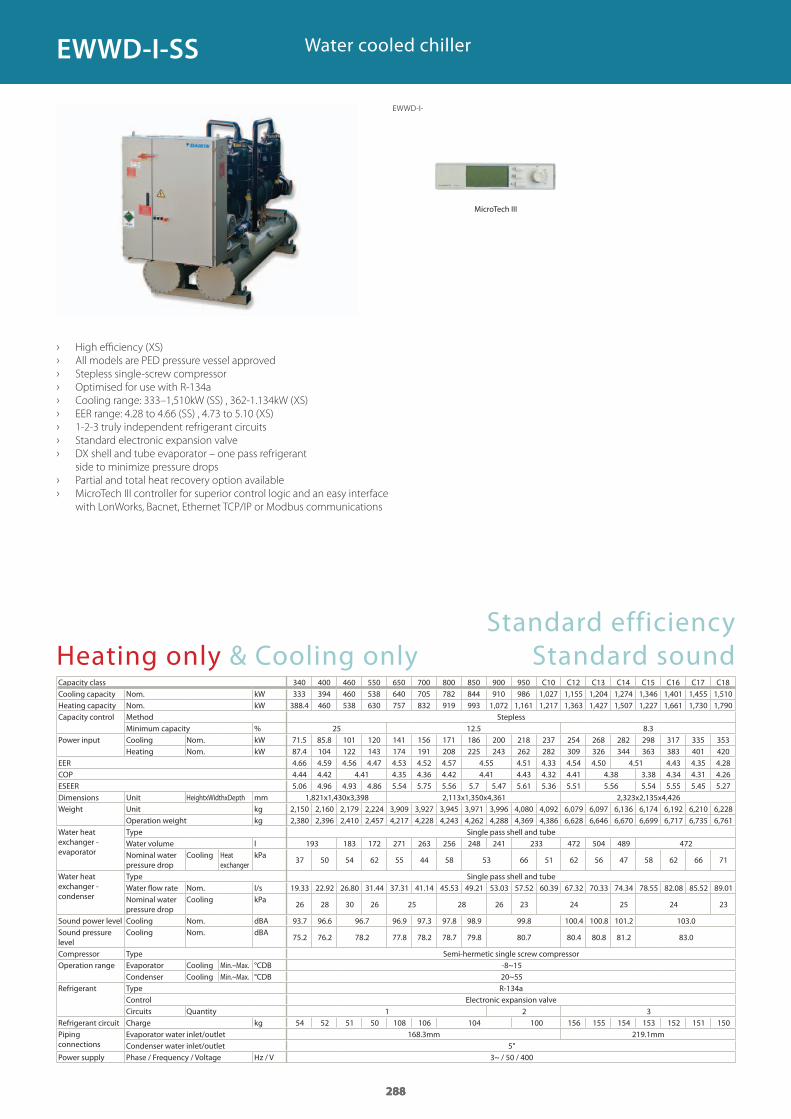
288
Heating only & Cooling onlyCapacity class 340 400 460 550 650 700 800 850 900 950 C10 C12 C13 C14 C15 C16 C17 C18Cooling capacity Nom. kWHeating capacity Nom. kWCapacity control Method Stepless
Minimum capacity %Power input Cooling Nom. kW
Heating Nom. kWEERCOPESEERDimensions Unit HeightxWidthxDepth mmWeight Unit kg
Operation weight kgWater heat exchanger - evaporator
Type Single pass shell and tubeWater volume lNominal water pressure drop
Cooling Heat exchanger
kPa
Water heat exchanger - condenser
Type Single pass shell and tubeWater flow rate Nom. l/sNominal water pressure drop
Cooling kPa
Sound power level Cooling Nom. dBASound pressure level
Cooling Nom. dBA
Compressor Type Semi-hermetic single screw compressorOperation range Evaporator Cooling Min.~Max. °CDB
Condenser Cooling Min.~Max. °CDBRefrigerant Type R-134a
Control Electronic expansion valveCircuits Quantity
Refrigerant circuit Charge kgPiping connections
Evaporator water inlet/outlet 168.3mm 219.1mmCondenser water inlet/outlet
Power supply Phase / Frequency / Voltage Hz / V
› High efficiency (XS)
› All models are PED pressure vessel approved
› Stepless single-screw compressor
› Optimised for use with R-134a
› Cooling range: 333–1,510kW (SS) , 362-1.134kW (XS)
› EER range: 4.28 to 4.66 (SS) , 4.73 to 5.10 (XS)
› 1-2-3 truly independent refrigerant circuits
› Standard electronic expansion valve
› DX shell and tube evaporator – one pass refrigerant
side to minimize pressure drops
› Partial and total heat recovery option available
› MicroTech III controller for superior control logic and an easy interface
with LonWorks, Bacnet, Ethernet TCP/IP or Modbus communications
Water cooled chiller
288
333 394 460 538 640 705 782 844 910 986 1,027 1,155 1,204 1,274 1,346 1,401 1,455 1,510 388.4 460 538 630 757 832 919 993 1,072 1,161 1,217 1,363 1,427 1,507 1,227 1,661 1,730 1,790
25 12.5 8.371.5 85.8 101 120 141 156 171 186 200 218 237 254 268 282 298 317 335 353 87.4 104 122 143 174 191 208 225 243 262 282 309 326 344 363 383 401 420 4.66 4.59 4.56 4.47 4.53 4.52 4.57 4.55 4.51 4.33 4.54 4.50 4.51 4.43 4.35 4.28 4.44 4.42 4.41 4.35 4.36 4.42 4.41 4.43 4.32 4.41 4.38 3.38 4.34 4.31 4.26 5.06 4.96 4.93 4.86 5.54 5.75 5.56 5.7 5.47 5.61 5.36 5.51 5.56 5.54 5.55 5.45 5.27
1,821x1,430x3,398 2,113x1,350x4,361 2,323x2,135x4,4262,150 2,160 2,179 2,224 3,909 3,927 3,945 3,971 3,996 4,080 4,092 6,079 6,097 6,136 6,174 6,192 6,210 6,2282,380 2,396 2,410 2,457 4,217 4,228 4,243 4,262 4,288 4,369 4,386 6,628 6,646 6,670 6,699 6,717 6,735 6,761
193 183 172 271 263 256 248 241 233 472 504 489 472
37 50 54 62 55 44 58 53 66 51 62 56 47 58 62 66 71
19.33 22.92 26.80 31.44 37.31 41.14 45.53 49.21 53.03 57.52 60.39 67.32 70.33 74.34 78.55 82.08 85.52 89.01
26 28 30 26 25 28 26 23 24 25 24 23
93.7 96.6 96.7 96.9 97.3 97.8 98.9 99.8 100.4 100.8 101.2 103.0
75.2 76.2 78.2 77.8 78.2 78.7 79.8 80.7 80.4 80.8 81.2 83.0
-8~1520~55
1 2 354 52 51 50 108 106 104 100 156 155 154 153 152 151 150
5"3~ / 50 / 400
288
EWWD-I-
EWWD-I-SS
MicroTech III
Standard efficiency Standard sound
GC_pre2_lowres.pdf 288 30/11/2011 12:31:55
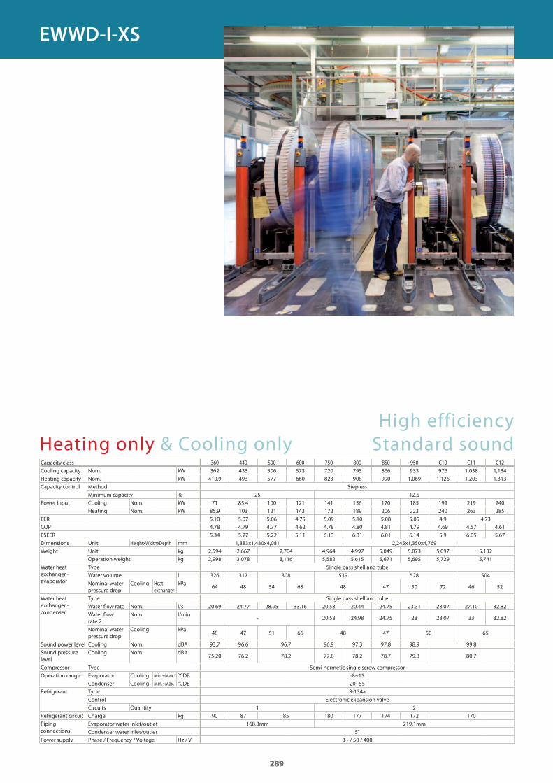
289
Heating only & Cooling onlyCapacity class 360 440 500 600 750 800 850 950 C10 C11 C12Cooling capacity Nom. kWHeating capacity Nom. kWCapacity control Method Stepless
Minimum capacity %Power input Cooling Nom. kW
Heating Nom. kWEERCOPESEERDimensions Unit HeightxWidthxDepth mmWeight Unit kg
Operation weight kgWater heat exchanger - evaporator
Type Single pass shell and tubeWater volume lNominal water pressure drop
Cooling Heat exchanger
kPa
Water heat exchanger - condenser
Type Single pass shell and tubeWater fl ow rate Nom. l/sWater fl ow rate 2
Nom. l/min
Nominal water pressure drop
Cooling kPa
Sound power level Cooling Nom. dBASound pressure level
Cooling Nom. dBA
Compressor Type Semi-hermetic single screw compressorOperation range Evaporator Cooling Min.~Max. °CDB
Condenser Cooling Min.~Max. °CDBRefrigerant Type R-134a
Control Electronic expansion valveCircuits Quantity
Refrigerant circuit Charge kgPiping connections
Evaporator water inlet/outlet 168.3mm 219.1mmCondenser water inlet/outlet
Power supply Phase / Frequency / Voltage Hz / V
High efficiencyStandard sound
289
362 433 506 573 720 795 866 933 976 1,038 1,134 410.9 493 577 660 823 908 990 1,069 1,126 1,203 1,313
25 12.571 85.4 100 121 141 156 170 185 199 219 240 85.9 103 121 143 172 189 206 223 240 263 285 5.10 5.07 5.06 4.75 5.09 5.10 5.08 5.05 4.9 4.73 4.78 4.79 4.77 4.62 4.78 4.80 4.81 4.79 4.69 4.57 4.61 5.34 5.27 5.22 5.11 6.13 6.31 6.01 6.14 5.9 6.05 5.67
1,883x1,430x4,081 2,245x1,350x4,7692,594 2,667 2,704 4,964 4,997 5,049 5,073 5,097 5,1322,998 3,078 3,116 5,582 5,615 5,671 5,695 5,729 5,741
326 317 308 539 528 504
64 48 54 68 48 47 50 72 46 52
20.69 24.77 28.95 33.16 20.58 20.44 24.75 23.31 28.07 27.10 32.82
- 20.58 24.98 24.75 28 28.07 33 32.82
48 47 51 66 48 47 50 65
93.7 96.6 96.7 96.9 97.3 97.8 98.9 99.8
75.20 76.2 78.2 77.8 78.2 78.7 79.8 80.7
-8~1520~55
1 290 87 85 180 177 174 172 170
5"3~ / 50 / 400
289
EWWD-I-XS
GC_pre2_lowres.pdf 289 30/11/2011 12:31:55
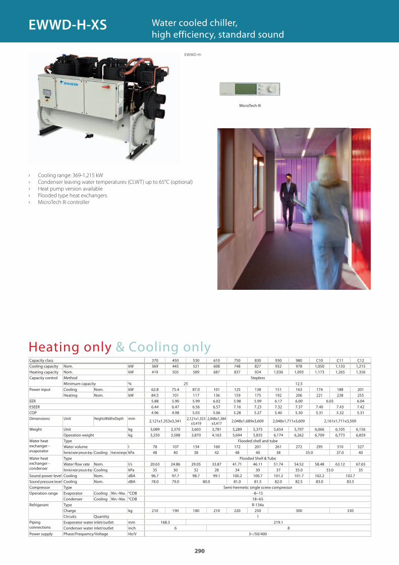
290
Heating only & Cooling onlyCapacity classCooling capacity Nom. kWHeating capacity Nom. kWCapacity control Method Stepless
Minimum capacity %Power input Cooling Nom. kW
Heating Nom. kWEERESEERCOPDimensions Unit HeightxWidthxDepth mm
Weight Unit kgOperation weight kg
Water heat exchanger - evaporator
Type Flooded shell and tubeWater volume lNominal water pressure drop Cooling Heat exchanger kPa
Water heat exchanger - condenser
Type Flooded Shell & TubeWater fl ow rate Nom. l/sNominal water pressure drop Cooling kPa
Sound power level Cooling Nom. dBASound pressure level Cooling Nom. dBACompressor Type Semi-hermetic single screw compressorOperation range Evaporator Cooling Min.~Max. °CDB
Condenser Cooling Min.~Max. °CDBRefrigerant Type R-134a
Charge kgCircuits Quantity
Piping connections
Evaporator water inlet/outlet mmCondenser water inlet/outlet inch
Power supply Phase/Frequency/Voltage Hz/V
› Cooling range: 369-1,215 kW
› Condenser leaving water temperatures (CLWT) up to 65°C (optional)
› Heat pump version available
› Flooded type heat exchangers
› MicroTech III controller
Water cooled chiller, high efficiency, standard sound
290
370 450 530 610 750 830 930 980 C10 C11 C12369 445 521 608 748 827 932 978 1,050 1,133 1,215 419 505 589 687 837 924 1,036 1,093 1,173 1,265 1,356
25 12.562.8 75.4 87.0 101 125 138 151 163 174 188 201 84.5 101 117 136 159 175 192 206 221 238 255 5.88 5.90 5.99 6.02 5.98 5.99 6.17 6.00 6.03 6.04 6.44 6.47 6.56 6.57 7.16 7.23 7.32 7.37 7.40 7.43 7.424.96 4.98 5.03 5.06 5.28 5.27 5.40 5.30 5.31 5.32 5.31
2,121x1,353x3,3412,121x1,353
x3,4192,048x1,384
x3,417 2,048x1,689x3,609 2,048x1,711x3,609 2,161x1,711x3,509
3,089 3,370 3,603 3,781 5,289 5,375 5,654 5,707 6,066 6,105 6,1563,250 3,588 3,870 4,163 5,694 5,835 6,174 6,262 6,709 6,773 6,859
78 107 134 160 172 201 261 272 295 310 32748 40 38 42 48 40 38 35.0 37.0 40
20.63 24.86 29.05 33.87 41.71 46.11 51.74 54.52 58.48 63.12 67.6535 30 32 28 34 30 37 35.0 33.0 3596.7 97.7 98.7 99.1 100.2 100.7 101.2 101.7 102.2 102.778.0 79.0 80.0 81.0 81.5 82.0 82.5 83.0 83.5
-8~1518~65
210 190 180 210 220 250 300 3301
168.3 219.16 8
3~/50/400
290
EWWD-H-
EWWD-H-XS
MicroTech III
GC_pre2_lowres.pdf 290 30/11/2011 12:31:56
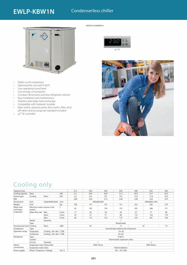
291
Cooling onlyCapacity class 012 020 026 030 040 055 065Cooling capacity Nom. kWPower input Cooling Nom. kWEERDimensions Unit HeightxWidthxDepth mmWeight Unit kgWater heat exchanger - evaporator
Minimum water volume in the system
l
Water flow rate Min. l/minNom. l/minMax. l/min
Model QuantityType Brazed plate
Sound power level Cooling Nom. dBACompressor Type Hermetically sealed scroll compressorOperation range Evaporator Cooling Min.~Max. °CDB
Condenser Cooling Min.~Max. °CDBRefrigerant Type R-407C
Control Thermostatic expansion valveCircuits Quantity
Piping connections
Evaporator water inlet/outlet FBSP 25mm FBSP 40mmEvaporator water drain Field installation
Power supply Phase / Frequency / Voltage Hz / V
Condenserless chiller
› Daikin scroll compressor
› Optimised for use with R-407C
› Low operating sound level
› Low energy consumption
› Compact dimensions and low refrigerant volume
› Easy installation and maintenance
› Stainless steel plate heat exchanger
› Compatible with hydraulic module
› Main switch, pressure ports, flow switch, filter, shut-
off valves and air purge are standard included
› μC² SE controller
291
12.1 20.0 26.8 31.2 40.0 53.7 62.4 4.2 6.6 8.5 10.1 13.4 17.8 20.3 2.88 3.03 3.15 3.09 2.99 3.02 3.07
600x600x600 600x600x1,200108 141 147 151 252 265 274
62 103 134 155 205 268 311
17 29 38 45 57 77 8935 57 77 89 115 154 17969 115 153 179 229 307 358
1
64 71 67 74
-10~2025~60
1 2
3N~ / 50 / 400
291
EWLP-KBW1N
EWLP012-030KBW1N
μC² SE
GC_pre2_lowres.pdf 291 30/11/2011 12:31:56
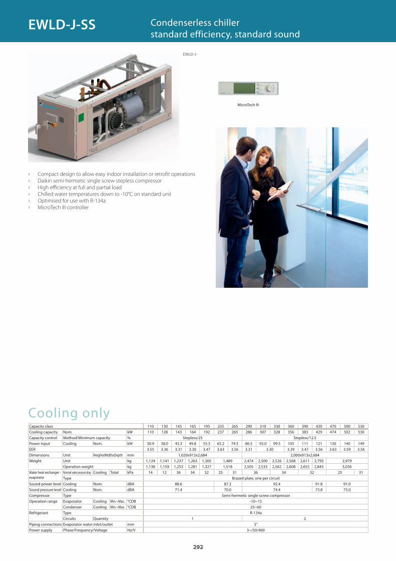
292
Cooling onlyCapacity classCooling capacity Nom. kWCapacity control Method/Minimum capacity % Stepless/25 Stepless/12.5Power input Cooling Nom. kWEERDimensions Unit HeightxWidthxDepth mmWeight Unit kg
Operation weight kgWater heat exchanger - evaporator
Nominal water pressure drop Cooling Total kPaType Brazed plate, one per circuit
Sound power level Cooling Nom. dBASound pressure level Cooling Nom. dBACompressor Type Semi-hermetic single screw compressorOperation range Evaporator Cooling Min.~Max. °CDB
Condenser Cooling Min.~Max. °CDBRefrigerant Type R-134a
Circuits QuantityPiping connections Evaporator water inlet/outlet mmPower supply Phase/Frequency/Voltage Hz/V
› Compact design to allow easy indoor installation or retrofi t operations
› Daikin semi-hermetic single screw stepless compressor
› High effi ciency at full and partial load
› Chilled water temperatures down to -10°C on standard unit
› Optimised for use with R-134a
› MicroTech III controller
Condenserless chillerstandard efficiency, standard sound
292
110 130 145 165 195 235 265 290 310 330 360 390 430 470 500 530110 128 143 164 192 237 265 286 307 328 356 383 429 474 502 530
30.9 38.0 43.3 49.8 55.3 65.2 74.5 86.5 93.0 99.5 105 111 121 130 140 149 3.55 3.36 3.31 3.30 3.47 3.63 3.56 3.31 3.30 3.39 3.47 3.56 3.63 3.59 3.56
1,020x913x2,684 2,000x913x2,6841,124 1,141 1,237 1,263 1,305 1,489 2,474 2,500 2,526 2,568 2,611 2,795 2,9791,138 1,159 1,253 1,281 1,327 1,518 2,505 2,533 2,562 2,608 2,655 2,845 3,036
14 12 36 34 32 25 31 36 34 32 25 31
88.6 87.2 92.4 91.8 91.0 71.4 70.0 74.4 73.8 73.0
-10~1525~60
1 23"
3~/50/400
292
EWLD-J-
EWLD-J-SS
MicroTech III
GC_pre2_lowres.pdf 292 30/11/2011 12:31:56
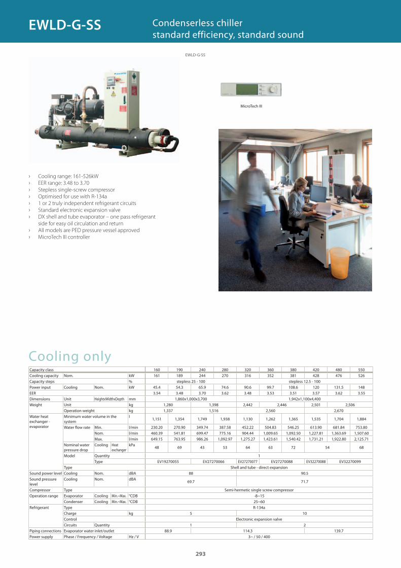
Cooling onlyCapacity class 160 190 240 280 320 360 380 420 480 550Cooling capacity Nom. kWCapacity steps % stepless 25 - 100 stepless 12.5 - 100Power input Cooling Nom. kWEERDimensions Unit HeightxWidthxDepth mmWeight Unit kg
Operation weight kgWater heat exchanger - evaporator
Minimum water volume in the system
l
Water fl ow rate Min. l/minNom. l/minMax. l/min
Nominal water pressure drop
Cooling Heat exchanger
kPa
Model QuantityType EV19270055 EV27270066 EV27270077 EV27270088 EV32270088 EV32270099
Type Shell and tube - direct expansionSound power level Cooling Nom. dBASound pressure level
Cooling Nom. dBA
Compressor Type Semi-hermetic single screw compressorOperation range Evaporator Cooling Min.~Max. °CDB
Condenser Cooling Min.~Max. °CDBRefrigerant Type R-134a
Charge kgControl Electronic expansion valveCircuits Quantity
Piping connections Evaporator water inlet/outletPower supply Phase / Frequency / Voltage Hz / V
› Cooling range: 161-526kW
› EER range: 3.48 to 3.70
› Stepless single-screw compressor
› Optimised for use with R-134a
› 1 or 2 truly independent refrigerant circuits
› Standard electronic expansion valve
› DX shell and tube evaporator – one pass refrigerant
side for easy oil circulation and return
› All models are PED pressure vessel approved
› MicroTech III controller
Condenserless chillerstandard efficiency, standard sound
161 189 244 270 316 352 381 428 476 526
45.4 54.3 65.9 74.6 90.6 99.7 108.6 120 131.5 148 3.54 3.48 3.70 3.62 3.48 3.53 3.51 3.57 3.62 3.55
1,860x1,000x3,700 1,942x1,100x4,4001,280 1,398 2,442 2,446 2,501 2,5061,337 1,516 2,560 2,670
1,151 1,354 1,749 1,938 1,130 1,262 1,365 1,535 1,704 1,884
230.20 270.90 349.74 387.58 452.22 504.83 546.25 613.90 681.84 753.80460.39 541.81 699.47 775.16 904.44 1,009.65 1,092.50 1,227.81 1,363.69 1,507.60649.15 763.95 986.26 1,092.97 1,275.27 1,423.61 1,540.42 1,731.21 1,922.80 2,125.71
48 69 43 53 64 63 72 54 68
1
88 90.5
69.7 71.7
-8~1525~60
5 10
1 288.9 114.3 139.7
3~ / 50 / 400
293
EWLD-G-SS
MicroTech III
EWLD-G-SS
GC_pre2_lowres.pdf 293 30/11/2011 12:31:57
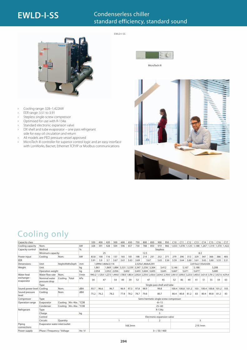
294
› Cooling range: 328–1,422kW
› EER range: 3.51 to 3.91
› Stepless single-screw compressor
› Optimised for use with R-134a
› Standard electronic expansion valve
› DX shell and tube evaporator – one pass refrigerant
side for easy oil circulation and return
› All models are PED pressure vessel approved
› MicroTech III controller for superior control logic and an easy interface
with LonWorks, Bacnet, Ethernet TCP/IP or Modbus communications
Condenserless chillerstandard efficiency, standard sound
Cooling onlyCapacity class 320 400 420 500 600 650 750 800 850 900 950 C10 C11 C12 C13 C14 C15 C16 C17Cooling capacity Nom. kWCapacity control Method % Stepless
Minimum capacityPower input Cooling Nom. kWEERDimensions Unit HeightxWidthxDepth mmWeight Unit kg
Operation weight kgWater heat exchanger - evaporator
Water fl ow rate Nom. l/minNominal water pressure drop
Cooling Total kPa
Type Single pass shell and tubeSound power level Cooling Nom. dBASound pressure level
Cooling Nom. dBA
Compressor Type Semi-hermetic single screw compressorOperation range Evaporator Cooling Min.~Max. °CDB
Condenser Cooling Min.~Max. °CDB 25~60Refrigerant Type R-134a
Charge kgControl Electronic expansion valveCircuits Quantity
Piping connections
Evaporator water inlet/outlet168.3mm 219.1mm
Power supply Phase / Frequency / Voltage Hz / V
294
328 391 428 504 596 657 730 788 850 919 966 1,033 1,078 1,125 1,188 1,267 1,319 1,370 1,422
25 12.5 8.383.8 100 116 137 165 181 198 214 231 252 271 279 296 312 329 347 366 386 405 3.91 3.9 3.7 3.67 3.61 3.63 3.69 3.67 3.65 3.56 3.59 3.64 3.60 3.61 3.65 3.60 3.55 3.51
1,899x1,464x3,114 2,325x1,464x4,391 2,415x2,135x4,4261,861 1,869 1,884 3,331 3,339 3,347 3,356 3,364 3,412 5,146 5,167 5,188 5,2082,054 2,052 2,056 3,602 3,603 3,604 3,605 3,645 5,667 5,671 5,677 5,680
940.2 1,120.8 1,227.0 1,444.8 1,708.8 1,883.4 2,092.8 2,259.0 2,436.6 2,634.6 2,769.0 2,961.0 3,090.0 3,225.0 3,405.6 3,631.8 3,781.2 3,927.6 4,076.4
34 47 54 49 39 52 47 45 52 46 49 41 51 55 59 63
93.7 96.6 96.7 96.9 97.3 97.8 98.9 99.8 100.4 100.8 101.2 103 100.4 100.8 101.2 103
75.2 76.2 78.2 77.8 78.2 78.7 79.8 80.7 80.4 80.8 81.2 83 80.4 80.8 81.2 83
-8~15
5
1 2 3
3~ / 50 / 400
294
EWLD-I-SS
MicroTech III
EWLD-I-SS
GC_pre2_lowres.pdf 294 30/11/2011 12:31:57
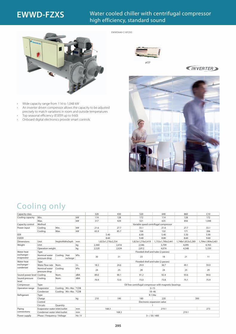
295
Cooling onlyCapacity class 320 430 520 640 860 C10Cooling capacity Min. kW
Max. kWCapacity control Method Variable speed centrifugal compressorPower input Cooling Min. kW
Cooling Max. kWEERESEERDimensions Unit HeightxWidthxDepth mmWeight Unit kg
Operation weight kgWater heat exchanger - evaporator
Type Flooded shell and tube (2 passes)Nominal water pressure drop
Cooling Heat exchanger
kPa
Water heat exchanger - condenser
Type Flooded shell and tube (2 passes)Water flow rate Nom. l/sNominal water pressure drop
Cooling kPa
Sound power level Cooling Nom. dBASound pressure level
Cooling Nom. dBA
Compressor Type Oil free centrifugal compressor with magnetic bearingsOperation range Evaporator Cooling Min.~Max. °CDB
Condenser Cooling Min.~Max. °CDBRefrigerant Type R-134a
Charge kgControl Electronic expansion valveCircuits Quantity
Piping connections
Evaporator water inlet/outlet mmCondenser water inlet/outlet mm
Power supply Phase / Frequency / Voltage Hz / V
› Wide capacity range from 114 to 1,048 kW
› An inverter driven compressor allows the capacity to be adjusted
precisely to match variations in room and outside temperatures
› Top seasonal efficiency (ESEER up to 9.60)
› Onboard digital electronics provide smart controls
Water cooled chiller with centrifugal compressor high efficiency, standard sound
295
114 128 172 114 128 172317 429 521 635 856 1,048
21.6 27.7 33.1 21.6 27.7 33.165.9 85.7 104 132 171 206
5.40 6.00 5.40 5.50 5.908.60 9.40 8.80 8.60 9.60
1,823x1,276x3,254 1,823x1,276x3,419 1,755x1,790x3,441 1,748x1,853x3,289 1,794x1,904x3,4012,360 2,416 2,546 3,709 4,095 4,7652,520 2,634 2,812 4,074 4,548 5,330
30 31 23 18 21 11
18.3 24.6 29.9 36.7 49.1 59.9
24 25 28 24 25 29
89.0 90.1 91.2 92.4 93.6 94.6
70.9 72.0 73.0 73.8 75.1 75.9
2~1518~46
210 190 180 220 300
1168.3 219.1 273
168.3 219.13~ / 50 / 400
295
EWWD640-C10FZXS
EWWD-FZXS
pCO2
GC_pre2_lowres.pdf 295 30/11/2011 12:31:57
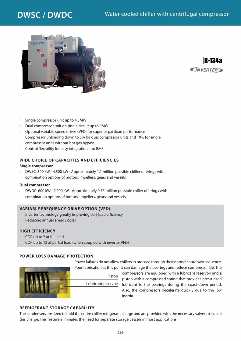
296
› Single compressor unit up to 4.5MW › Dual compressor unit on single circuit up to 9MW › Optional variable speed drives (VFD) for superior partload performance › Compressor unloading down to 5% for dual compressor units and 10% for single
compressor units without hot gas bypass › Control flexibility for easy integration into BMS
WIDE CHOICE OF CAPACITIES AND EFFICIENCIES
Single compressor
› DWSC: 300 kW - 4,500 kW - Approximately 1.1 million possible chiller offerings with combination options of motors, impellers, gears and vessels
Dual compressor
› DWDC: 600 kW - 9,000 kW - Approximately 0.75 million possible chiller offerings with
combination options of motors, impellers, gears and vessels
VARIABLE FREQUENCY DRIVE OPTION (VFD)
› Inverter technology greatly improving part load efficiency › Reducing annual energy costs
HIGH EFFICIENCY
› COP up to 7 at full load › COP up to 12 at partial load (when coupled with inverter VFD)
POWER LOSS DAMAGE PROTECTION
Power failures do not allow chillers to proceed through their normal shutdown sequence. Poor lubrication at this point can damage the bearings and reduce compressor life. The
compressors are equipped with a lubricant reservoir and a piston with a compressed spring that provides pressurized lubricant to the bearings during the coast-down period. Also, the compressors decelerate quickly due to the low inertia.
Piston
Lubricant reservoir
REFRIGERANT STORAGE CAPABILITY
The condensers are sized to hold the entire chiller refrigerant charge and are provided with the necessary valves to isolate this charge. This feature eliminates the need for separate storage vessels in most applications.
DWSC / DWDC Water cooled chiller with centrifugal compressor
GC_pre2_lowres.pdf 296 30/11/2011 12:31:58
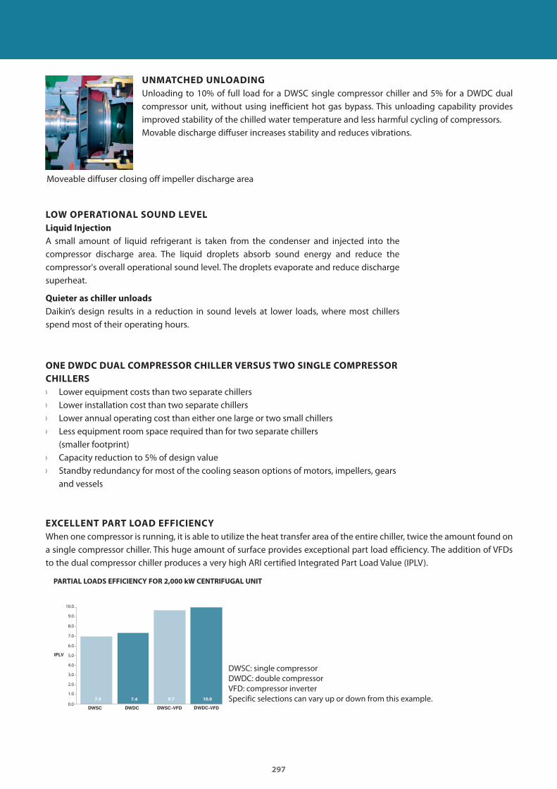
297
D D D D
UNMATCHED UNLOADING
Unloading to 10% of full load for a DWSC single compressor chiller and 5% for a DWDC dual compressor unit, without using inefficient hot gas bypass. This unloading capability provides improved stability of the chilled water temperature and less harmful cycling of compressors.Movable discharge diffuser increases stability and reduces vibrations.
Moveable diffuser closing off impeller discharge area
LOW OPERATIONAL SOUND LEVEL
Liquid Injection
A small amount of liquid refrigerant is taken from the condenser and injected into the compressor discharge area. The liquid droplets absorb sound energy and reduce the compressor's overall operational sound level. The droplets evaporate and reduce discharge superheat.
Quieter as chiller unloads
Daikin’s design results in a reduction in sound levels at lower loads, where most chillers spend most of their operating hours.
ONE DWDC DUAL COMPRESSOR CHILLER VERSUS TWO SINGLE COMPRESSOR
CHILLERS
› Lower equipment costs than two separate chillers › Lower installation cost than two separate chillers › Lower annual operating cost than either one large or two small chillers › Less equipment room space required than for two separate chillers
(smaller footprint) › Capacity reduction to 5% of design value › Standby redundancy for most of the cooling season options of motors, impellers, gears
and vessels
EXCELLENT PART LOAD EFFICIENCY
When one compressor is running, it is able to utilize the heat transfer area of the entire chiller, twice the amount found on a single compressor chiller. This huge amount of surface provides exceptional part load efficiency. The addition of VFDs to the dual compressor chiller produces a very high ARI certified Integrated Part Load Value (IPLV).
PARTIAL LOADS EFFICIENCY FOR 2,000 kW CENTRIFUGAL UNIT
DWSC: single compressorDWDC: double compressorVFD: compressor inverterSpecific selections can vary up or down from this example.
10.0
9.0
8.0
7.0
6.0
5.0
4.0
3.0
2.0
1.0
0.07.0 7.4 9.7 10.0
GC_pre2_lowres.pdf 297 30/11/2011 12:31:58
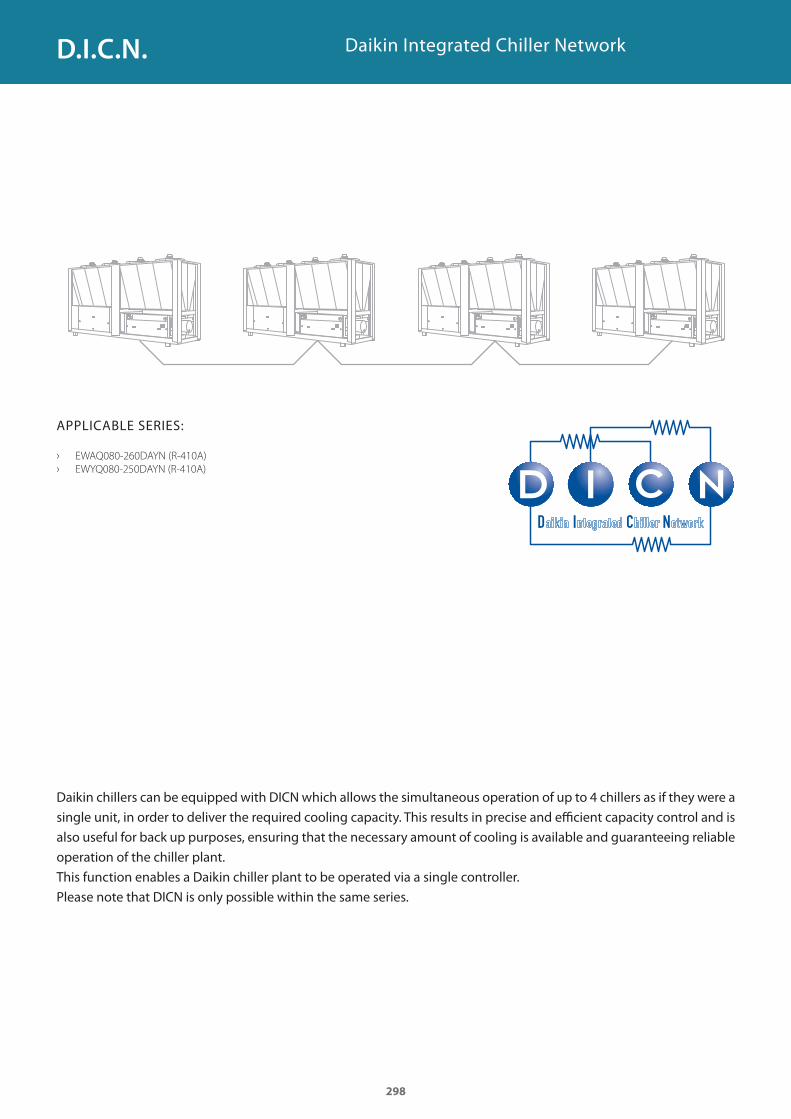
Daikin Integrated Chiller Network
APPLICABLE SERIES:
› EWAQ080-260DAYN (R-410A)
› EWYQ080-250DAYN (R-410A)
Daikin chillers can be equipped with DICN which allows the simultaneous operation of up to 4 chillers as if they were a
single unit, in order to deliver the required cooling capacity. This results in precise and efficient capacity control and is
also useful for back up purposes, ensuring that the necessary amount of cooling is available and guaranteeing reliable
operation of the chiller plant.
This function enables a Daikin chiller plant to be operated via a single controller.
Please note that DICN is only possible within the same series.
298
D.I.C.N.
GC_pre2_lowres.pdf 298 30/11/2011 12:31:58
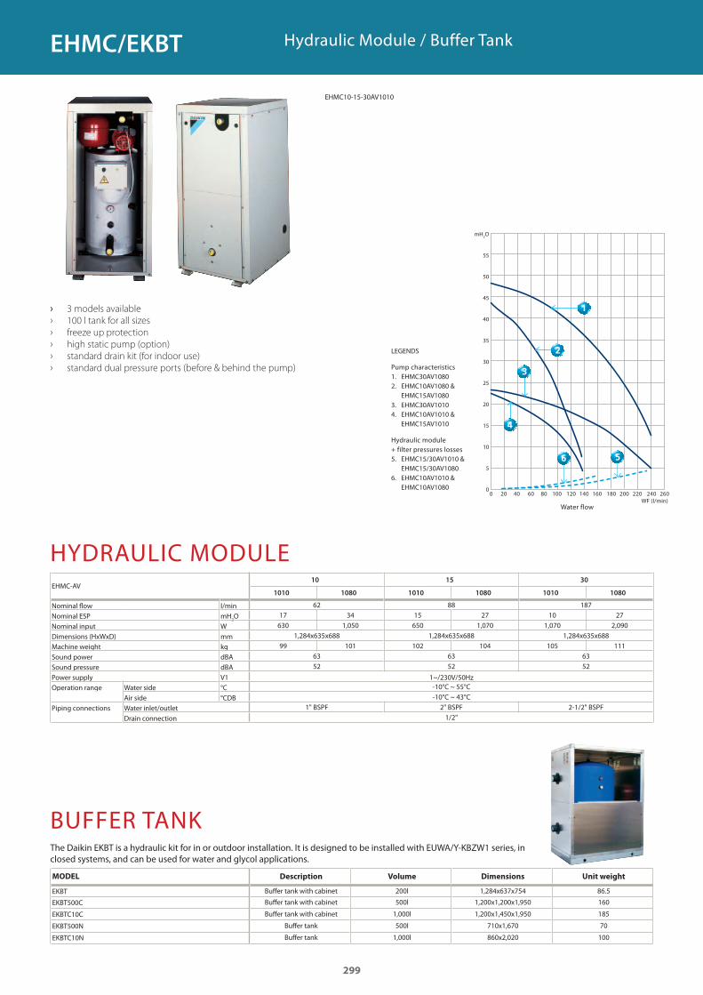
Hydraulic Module / Buffer Tank
› 3 models available
› 100 l tank for all sizes
› freeze up protection
› high static pump (option)
› standard drain kit (for indoor use)
› standard dual pressure ports (before & behind the pump)
HYDRAULIC MODULEEHMC-AV
Nominal flow l/minNominal ESP mH
2O
Nominal input WDimensions (HxWxD) mmMachine weight kgSound power dBASound pressure dBAPower supply V1 1~/230V/50HzOperation range Water side °C
Air side °CDBPiping connections Water inlet/outlet
Drain connection
BUFFER TANK
Water flow
mH2O
55
50
45
40
35
30
25
20
15
10
5
00 20 40 60 80 100 120 140 160 180 200 220 240 260 WF (l/min)
LEGENDS
Pump characteristics1. EHMC30AV10802. EHMC10AV1080 &
EHMC15AV10803. EHMC30AV10104. EHMC10AV1010 &
EHMC15AV1010
Hydraulic module + filter pressures losses5. EHMC15/30AV1010 &
EHMC15/30AV10806. EHMC10AV1010 &
EHMC10AV1080
MODEL Description Volume Dimensions Unit weight
EKBT Buffer tank with cabinet 200l 1,284x637x754 86.5
EKBT500C Buffer tank with cabinet 500l 1,200x1,200x1,950 160
EKBTC10C Buffer tank with cabinet 1,000l 1,200x1,450x1,950 185
EKBT500N Buffer tank 500l 710x1,670 70
EKBTC10N Buffer tank 1,000l 860x2,020 100
The Daikin EKBT is a hydraulic kit for in or outdoor installation. It is designed to be installed with EUWA/Y-KBZW1 series, in closed systems, and can be used for water and glycol applications.
10 15 30
1010 1080 1010 1080 1010 1080
62 88 18717 34 15 27 10 27
630 1,050 650 1,070 1,070 2,0901,284x635x688 1,284x635x688 1,284x635x688
99 101 102 104 105 11163 63 6352 52 52
-10°C ~ 55°C-10°C ~ 43°C
1" BSPF 2" BSPF 2-1/2" BSPF1/2"
299
EHMC/EKBT
›
EHMC10-15-30AV1010
GC_pre2_lowres.pdf 299 30/11/2011 12:31:58
GC_pre2_lowres.pdf 300 30/11/2011 12:31:58
301
) ���6.7�8�.25Cassette units 303
FWC-BT/BF 303FWF-BT/BF 304FWC-AT/AF 305FWF-CT 306
Concealed ceiling units 307
FWB-BT 307FWB-JT/JF 308
Wall mounted unit 309
FWT-BT 309
Flexi type units 310
FWL-DT/DF 310FWM-DT/DF 311FWD-AT/AF 312
Floor standing unit 313
FWV-DT/DF 313
For more information on Options & Accessories, please refer to page 362 of this catalogue.
GC_pre2_lowres.pdf 301 30/11/2011 12:31:59
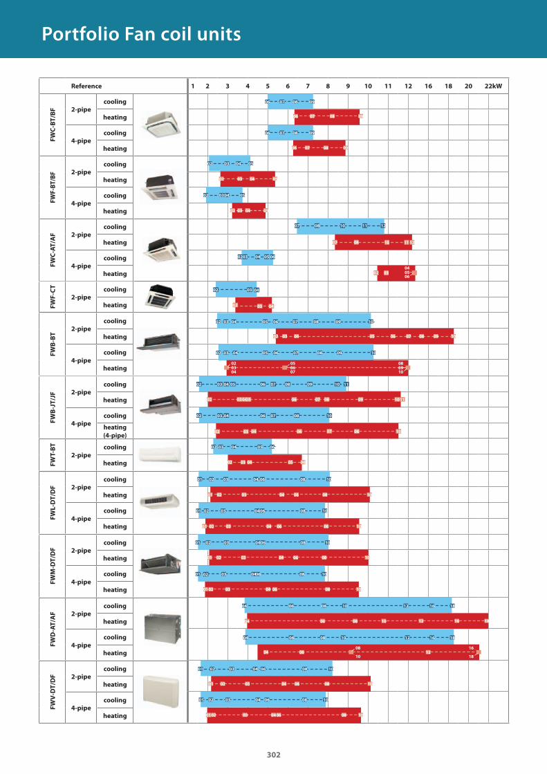
Portfolio Fan coil units
1 2 3 4 5 6 7 8 9 10 11 12 16 18 20 22kWReference
FWC
-BT/B
F 2-pipe
cooling
heating
4-pipe
cooling
heating
FW
F-B
T/B
F 2-pipe
cooling
heating
4-pipe
cooling
heating
FWC
-AT/A
F 2-pipe
cooling
heating
4-pipe
cooling
heating
FW
F-C
T
2-pipe
cooling
heating
FWB
-JT/J
F 2-pipe
cooling
heating
4-pipe
cooling
heating
(4-pipe)
FW
T-B
T
2-pipe
cooling
heating
FW
V-D
T/D
F 2-pipe
cooling
heating
4-pipe
cooling
heating
FWB
-BT
2-pipe
cooling
heating
4-pipe
cooling
heating
FWD
-AT/A
F 2-pipe
cooling
heating
4-pipe
cooling
heating
FWM
-DT/D
F 2-pipe
cooling
heating
4-pipe
cooling
heating
FW
L-D
T/D
F 2-pipe
cooling
heating
4-pipe
cooling
heating
302
02 03 04
02 03 04
02 03 05
02 03 04 05 06
04 06
04
04
04 06 08 10 12 16 18
08 10 12 16 18
08 10 12 1816
1218
1608
100604
06
06
07
07
07
06
06
06
02
02
03
03
03
04
04
04
05
05
05
08
08
09
09
09
10
10
10
0607
050910
0802
0403
02 08
06
06
07
07
08
08
09
09
06 07 08
06 07 08 09
09
03 04
02 03 04
02
05
05
02 0304 05
03 0402 05
02 03 06 08 10
01 02 03 04 06 08 10
02 03 06 08 10
02 03 0406 08
04
04
10
01
01
01
02
02 03 04 06 07 08
05 06 07 08 09 1110
02 03 04 06 10
03 04 05 06 08 09 10 11
07 08
02 07
10
0304
02 03 06 08 10
01 02
02
03
03
03
04
04
0604
06
06
08
08
08 10
10
04
1002
01
01
01
03
03
03
04
02
02
03
01
02
04
04
0604
06
06
06
08
08
08
08
10
10
10
10
0202
01
01
01
07
02 04 05 06
08 10 11 12
02 0304
07 08 10 11 12
03
0506
04
GC_pre2_lowres.pdf 302 30/11/2011 12:31:59
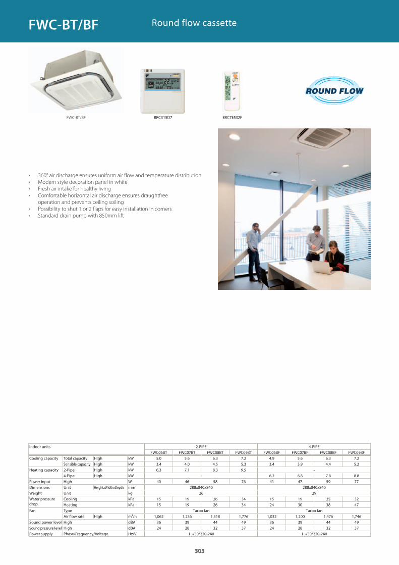
303
Indoor units 2-PIPE 4-PIPE
Cooling capacity Total capacity High kWSensible capacity High kW
Heating capacity 2-Pipe High kW4-Pipe High kW
Power input High WDimensions Unit HeightxWidthxDepth mmWeight Unit kgWater pressure drop
Cooling kPaHeating kPa
Fan Type Turbo fan Turbo fanAir flow rate High m³/h
Sound power level High dBASound pressure level High dBAPower supply Phase/Frequency/Voltage Hz/V
› 360° air discharge ensures uniform air flow and temperature distribution
› Modern style decoration panel in white
› Fresh air intake for healthy living
› Comfortable horizontal air discharge ensures draughtfree
operation and prevents ceiling soiling
› Possibility to shut 1 or 2 flaps for easy installation in corners
› Standard drain pump with 850mm lift
Round flow cassette
303
FWC06BT FWC07BT FWC08BT FWC09BT FWC06BF FWC07BF FWC08BF FWC09BF5.0 5.6 6.3 7.2 4.9 5.6 6.3 7.2 3.4 4.0 4.5 5.3 3.4 3.9 4.4 5.2 6.3 7.1 8.3 9.5 -
- 6.2 6.8 7.8 8.8 40 46 58 76 41 47 59 77
288x840x840 288x840x84026 29
15 19 26 34 15 19 25 3215 19 26 34 24 30 38 47
1,062 1,236 1,518 1,776 1,032 1,200 1,476 1,74636 39 44 49 36 39 44 4924 28 32 37 24 28 32 37
1~/50/220-240 1~/50/220-240
303
FWC-BT/BF
FWC-BT/BF
BRC315D7 BRC7E532F
GC_pre2_lowres.pdf 303 30/11/2011 12:31:59
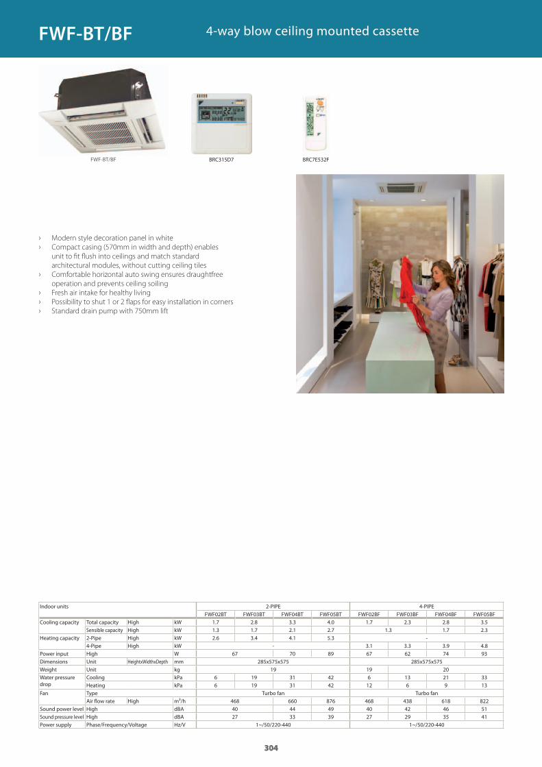
304
Indoor units 2-PIPE 4-PIPE
Cooling capacity Total capacity High kWSensible capacity High kW
Heating capacity 2-Pipe High kW4-Pipe High kW
Power input High WDimensions Unit HeightxWidthxDepth mmWeight Unit kgWater pressure drop
Cooling kPaHeating kPa
Fan Type Turbo fan Turbo fanAir flow rate High m³/h
Sound power level High dBASound pressure level High dBAPower supply Phase/Frequency/Voltage Hz/V
› Modern style decoration panel in white
› Compact casing (570mm in width and depth) enables
unit to fit flush into ceilings and match standard
architectural modules, without cutting ceiling tiles
› Comfortable horizontal auto swing ensures draughtfree
operation and prevents ceiling soiling
› Fresh air intake for healthy living
› Possibility to shut 1 or 2 flaps for easy installation in corners
› Standard drain pump with 750mm lift
4-way blow ceiling mounted cassette
304
FWF02BT FWF03BT FWF04BT FWF05BT FWF02BF FWF03BF FWF04BF FWF05BF1.7 2.8 3.3 4.0 1.7 2.3 2.8 3.5 1.3 1.7 2.1 2.7 1.3 1.7 2.3 2.6 3.4 4.1 5.3 -
- 3.1 3.3 3.9 4.8 67 70 89 67 62 74 93
285x575x575 285x575x57519 19 20
6 19 31 42 6 13 21 336 19 31 42 12 6 9 13
468 660 876 468 438 618 82240 44 49 40 42 46 5127 33 39 27 29 35 41
1~/50/220-440 1~/50/220-440
304
FWF-BT/BF
FWF-BT/BF
BRC315D7 BRC7E532F
GC_pre2_lowres.pdf 304 30/11/2011 12:31:59
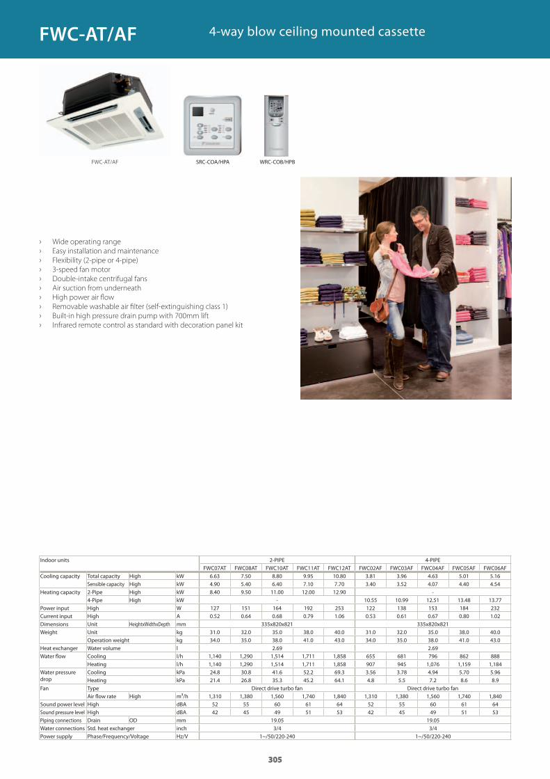
305
Indoor units 2-PIPE 4-PIPE
Cooling capacity Total capacity High kWSensible capacity High kW
Heating capacity 2-Pipe High kW4-Pipe High kW
Power input High WCurrent input High ADimensions Unit HeightxWidthxDepth mmWeight Unit kg
Operation weight kgHeat exchanger Water volume lWater flow Cooling l/h
Heating l/hWater pressure drop
Cooling kPaHeating kPa
Fan Type Direct drive turbo fan Direct drive turbo fanAir flow rate High m³/h
Sound power level High dBASound pressure level High dBAPiping connections Drain OD mmWater connections Std. heat exchanger inchPower supply Phase/Frequency/Voltage Hz/V
› Wide operating range
› Easy installation and maintenance
› Flexibility (2-pipe or 4-pipe)
› 3-speed fan motor
› Double-intake centrifugal fans
› Air suction from underneath
› High power air flow
› Removable washable air filter (self-extinguishing class 1)
› Built-in high pressure drain pump with 700mm lift
› Infrared remote control as standard with decoration panel kit
4-way blow ceiling mounted cassette
305
FWC07AT FWC08AT FWC10AT FWC11AT FWC12AT FWC02AF FWC03AF FWC04AF FWC05AF FWC06AF6.63 7.50 8.80 9.95 10.80 3.81 3.96 4.63 5.01 5.16 4.90 5.40 6.40 7.10 7.70 3.40 3.52 4.07 4.40 4.54 8.40 9.50 11.00 12.00 12.90 -
- 10.55 10.99 12.51 13.48 13.77 127 151 164 192 253 122 138 153 184 2320.52 0.64 0.68 0.79 1.06 0.53 0.61 0.67 0.80 1.02
335x820x821 335x820x82131.0 32.0 35.0 38.0 40.0 31.0 32.0 35.0 38.0 40.034.0 35.0 38.0 41.0 43.0 34.0 35.0 38.0 41.0 43.0
2.69 2.691,140 1,290 1,514 1,711 1,858 655 681 796 862 8881,140 1,290 1,514 1,711 1,858 907 945 1,076 1,159 1,18424.8 30.8 41.6 52.2 69.3 3.56 3.78 4.94 5.70 5.9621.4 26.8 35.3 45.2 64.1 4.8 5.5 7.2 8.6 8.9
1,310 1,380 1,560 1,740 1,840 1,310 1,380 1,560 1,740 1,84052 55 60 61 64 52 55 60 61 6442 45 49 51 53 42 45 49 51 53
19.05 19.053/4 3/4
1~/50/220-240 1~/50/220-240
305
FWC-AT/AF
FWC-AT/AF
SRC-COA/HPA WRC-COB/HPB
GC_pre2_lowres.pdf 305 30/11/2011 12:32:00
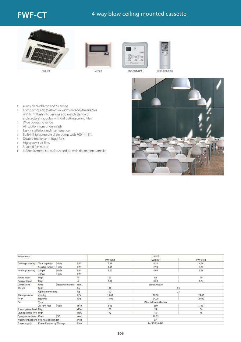
306
Indoor units 2-PIPE
Cooling capacity Total capacity High kWSensible capacity High kW
Heating capacity 2-Pipe High kW4-Pipe High kW
Power input High WCurrent input High ADimensions Unit HeightxWidthxDepth mmWeight Unit kg
Operation weight kgWater pressure drop
Cooling kPaHeating kPa
Fan Type Direct drive turbo fanAir flow rate High m³/h
Sound power level High dBASound pressure level High dBAPiping connections Drain OD mmWater connections Std. heat exchanger inchPower supply Phase/Frequency/Voltage Hz/V
› 4 way air discharge and air swing
› Compact casing (570mm in width and depth) enables
unit to fit flush into ceilings and match standard
architectural modules, without cutting ceiling tiles
› Wide operating range
› Air suction from underneath
› Easy installation and maintenance
› Built-in high pressure drain pump with 700mm lift
› Double-intake centrifugal fans
› High power air flow
› 3-speed fan motor
› Infrared remote control as standard with decoration panel kit
4-way blow ceiling mounted cassette
306
FWF02CT FWF03CT FWF04CT2.49 4.10 4.54 1.91 2.93 3.37 3.52 4.69 5.28
-63 64 790.27 0.28 0.34
250x570x57022 2322 23
19.00 27.00 29.0017.00 24.00 27.00
646 680 74852 54 5642 45 48
19.053/4
1~/50/220-440
306
FWF-CT MERCA WRC-COB/HPB
FWF-CT
SRC-COA/HPA
GC_pre2_lowres.pdf 306 30/11/2011 12:32:00
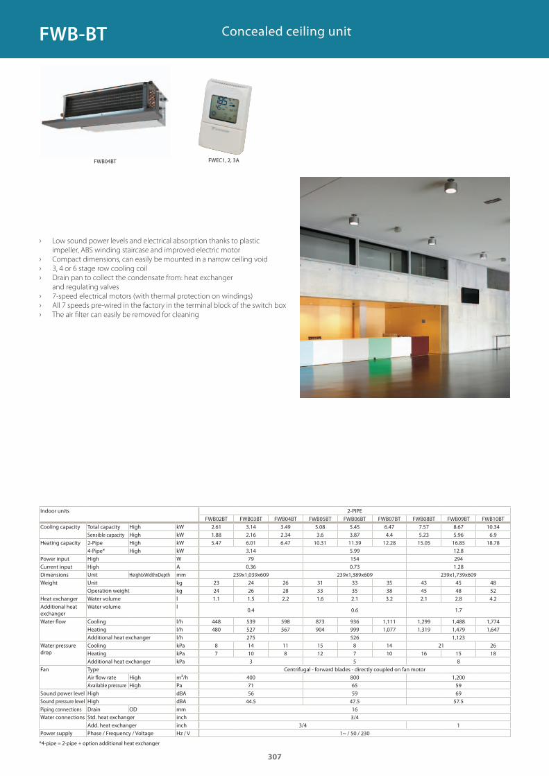
Concealed ceiling unit
› Low sound power levels and electrical absorption thanks to plastic
impeller, ABS winding staircase and improved electric motor
› Compact dimensions, can easily be mounted in a narrow ceiling void
› 3, 4 or 6 stage row cooling coil
› Drain pan to collect the condensate from: heat exchanger
and regulating valves
› 7-speed electrical motors (with thermal protection on windings)
› All 7 speeds pre-wired in the factory in the terminal block of the switch box
› The air filter can easily be removed for cleaning
Indoor units 2-PIPE
Cooling capacity Total capacity High kWSensible capacity High kW
Heating capacity 2-Pipe High kW4-Pipe* High kW
Power input High WCurrent input High ADimensions Unit HeightxWidthxDepth mmWeight Unit kg
Operation weight kgHeat exchanger Water volume lAdditional heat exchanger
Water volume l
Water flow Cooling l/hHeating l/hAdditional heat exchanger l/h
Water pressure drop
Cooling kPaHeating kPaAdditional heat exchanger kPa
Fan Type Centrifugal - forward blades - directly coupled on fan motorAir flow rate High m³/hAvailable pressure High Pa
Sound power level High dBASound pressure level High dBAPiping connections Drain OD mmWater connections Std. heat exchanger inch
Add. heat exchanger inchPower supply Phase / Frequency / Voltage Hz / V
*4-pipe = 2-pipe + option additional heat exchanger
FWB02BT FWB03BT FWB04BT FWB05BT FWB06BT FWB07BT FWB08BT FWB09BT FWB10BT2.61 3.14 3.49 5.08 5.45 6.47 7.57 8.67 10.341.88 2.16 2.34 3.6 3.87 4.4 5.23 5.96 6.95.47 6.01 6.47 10.31 11.39 12.28 15.05 16.85 18.78
3.14 5.99 12.879 154 2940.36 0.73 1.28
239x1,039x609 239x1,389x609 239x1,739x60923 24 26 31 33 35 43 45 4824 26 28 33 35 38 45 48 521.1 1.5 2.2 1.6 2.1 3.2 2.1 2.8 4.2
0.4 0.6 1.7
448 539 598 873 936 1,111 1,299 1,488 1,774480 527 567 904 999 1,077 1,319 1,479 1,647
275 526 1,1238 14 11 15 8 14 21 267 10 8 12 7 10 16 15 18
3 5 8
400 800 1,20071 65 5956 59 69
44.5 47.5 57.5163/4
3/4 11~ / 50 / 230
307
FWB-BT
FWEC1, 2, 3AFWB04BT
GC_pre2_lowres.pdf 307 30/11/2011 12:32:00
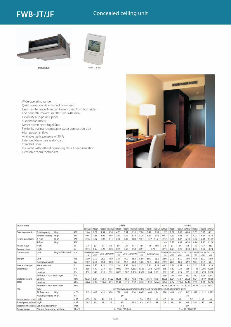
Concealed ceiling unit
› Wide operating range
› Quiet operation via enlarged fan wheels
› Easy maintenance: filter can be removed from both sides
and beneath (maximum filter size is 400mm)
› Flexibility (2-pipe or 4-pipe)
› 4-speed fan motor
› Direct driven centrifugal fans
› Flexibility via interchangeable water connection side
› High power air flow
› Available static pressure of 30 Pa
› Extended drain pan as standard
› Standard Filter
› Insulated with self-extinguishing class 1 heat insulation
› Electronic room thermostat
Indoor units 2-PIPE 4-PIPEFWB02JT FWB03JT FWB04JT FWB05JT FWB06JT FWB07JT FWB08JT FWB09JT FWB10JT FWB11JT FWB02JF FWB03JF FWB04JF FWB06JF FWB07JF FWB08JF FWB10JF
Cooling capacity Total capacity High kWSensible capacity High kW
Heating capacity 2-Pipe High kW4-Pipe High kW
Power input High WCurrent input High ADimensions Unit HeightxWidthxDepth mm
Weight Unit kgOperation weight kg
Heat exchanger Water volume lWater flow Cooling l/h
Heating l/hAdditional heat exchanger l/h
Water pressure drop
Cooling kPaHeating kPaAdditional heat exchanger kPa
Fan Type Direct driven centrifugal fan (forward-curved blades)hot-galvanised steelAir flow rate High m³/hAvailable pressure High Pa
Sound power level High dBASound pressure level High dBAWater connections Std. heat exchanger inchPower supply Phase / Frequency / Voltage Hz / V
1.64 2.67 2.99 3.34 4.81 5.31 6.16 7.26 8.49 8.99 1.67 2.67 3.03 4.88 5.33 6.53 8.210.94 1.88 1.95 2.07 3.40 4.15 4.39 5.06 6.37 6.41 0.97 1.83 1.93 3.41 4.01 4.91 6.282.16 3.62 3.97 4.11 6.30 7.47 8.09 9.64 11.57 11.71 2.12 3.69 3.87 6.40 7.52 9.01 11.09
- 2.49 3.92 4.43 6.70 8.16 9.56 11.6834 53 57 54 86 121 117 134 164 166 34 51 54 84 117 137 1630.15 0.24 0.26 0.25 0.39 0.55 0.53 0.61 0.75 0.15 0.23 0.25 0.38 0.53 0.62 0.74
251x814 x590
251x984 x590
251x1,114x590251x1,314
x590251x1,564x590
251x1,664 x590
251x1,924x590251x814 x590
251x984 x590
251x1,114 x590
251x1,314 x590
251x1,564 x590
251x1,664 x590
251x1,924 x590
20.0 23.0 28.0 31.0 33.0 44.0 48.0 52.0 50.0 56.0 22.0 27.0 31.0 36.0 48.0 52.0 56.020.7 24.0 29.1 32.5 34.4 45.8 50.4 54.6 52.4 59.1 22.9 28.3 32.5 37.9 50.4 54.6 59.10.69 0.95 1.14 1.52 1.44 1.82 2.42 2.62 2.36 3.14 0.92 1.26 1.52 1.92 2.42 2.62 3.14386 549 739 803 1,022 1,109 1,383 1,523 1,764 1,910 386 530 724 986 1,138 1,296 1,660386 549 738 802 1,020 1,107 1,336 1,524 1,764 1,911 387 530 725 985 1,139 1,299 1,660
- 269 391 493 663 820 924 1,14210.91 8.34 15.64 11.22 31.31 12.56 7.62 9.83 21.71 16.81 10.95 8.24 15.67 29.95 9.24 12.49 19.388.86 6.76 12.84 9.21 25.87 11.13 6.57 8.60 18.56 14.46 8.94 6.64 12.84 24.16 7.89 9.67 16.50
- 10.66 24.73 41.72 81.63 25.31 31.33 50.03
262 428 431 428 757 945 950 1,066 1,463 1,341 220 424 437 747 898 1,112 1,38530 30
47.5 52 49 50 52 55 55.5 56 47 52 50 52 55 5635.5 40 37 38 40 39.5 43 43.5 44 35 40 38 40 39.5 43 44
3/4 3/41~ / 50 / 220-240 1~ / 50 / 220-240
308
FWB-JT/JF
FWB02JT/JF FWEC1, 2, 3A
GC_pre2_lowres.pdf 308 30/11/2011 12:32:00
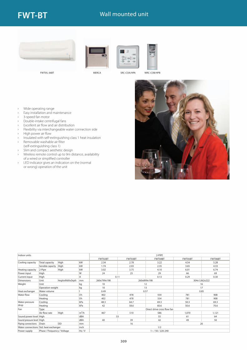
Wall mounted unit
› Wide operating range
› Easy installation and maintenance
› 3-speed fan motor
› Double-intake centrifugal fans
› Excellent air flow and air distribution
› Flexibility via interchangeable water connection side
› High power air flow
› Insulated with self-extinguishing class 1 heat insulation
› Removable washable air filter
(self-extinguishing class 1)
› Slim and compact aesthetic design
› Wireless remote control up to 9m distance, availability
of a wired or simplified controller
› LED indicator gives an indication on the (normal
or wrong) operation of the unit
Indoor units 2-PIPEFWT02BT FWT03BT FWT04BT FWT05BT FWT06BT
Cooling capacity Total capacity High kWSensible capacity High kW
Heating capacity 2-Pipe High kWPower input High WCurrent input High ADimensions Unit HeightxWidthxDepth mmWeight Unit kg
Operation weight kgHeat exchanger Water volume lWater flow Cooling l/h
Heating l/hWater pressure drop
Cooling kPaHeating kPa
Fan Type Direct drive cross flow fanAir flow rate High m³/h
Sound power level High dBASound pressure level High dBAPiping connections Drain OD mmWater connections Std. heat exchanger inchPower supply Phase / Frequency / Voltage Hz / V
2.34 2.78 3.22 4.54 5.281.74 2.03 2.35 3.65 4.333.02 3.75 4.10 6.01 6.7424 25 29 66 69
0.11 0.13 0.29 0.30260x799x198 260x899x198 304x1,062x222
10 12 1610 13 170.49 0.57 0.85402 478 554 781 908402 478 554 781 90848.3 64.7 69.3 50.3 69.342 58.6 60.6 50.6 70.6
467 510 586 1,070 1,12153 55 61 64
40 39 42 49 5016 20
1/21~ / 50 / 220-240
309
FWT-BT
MERCAFWT05, 06BT SRC-COA/HPA WRC-COB/HPB
GC_pre2_lowres.pdf 309 30/11/2011 12:32:01
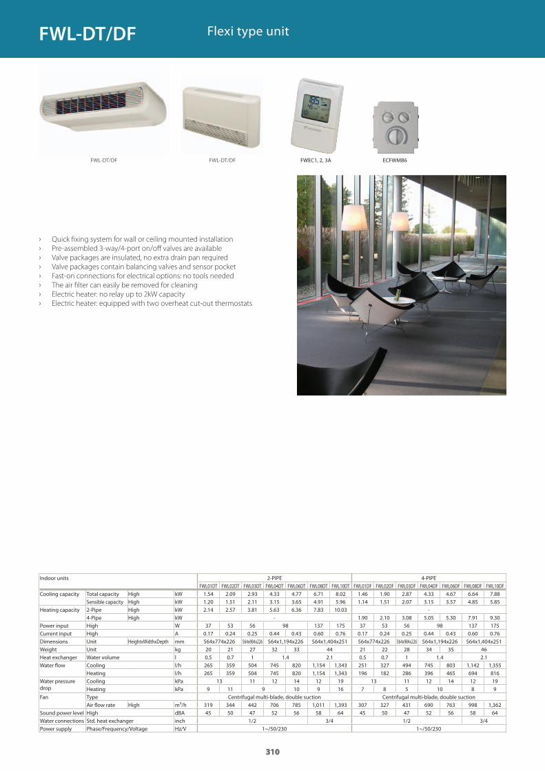
310
Indoor units 2-PIPE 4-PIPE
Cooling capacity Total capacity High kWSensible capacity High kW
Heating capacity 2-Pipe High kW4-Pipe High kW
Power input High WCurrent input High ADimensions Unit HeightxWidthxDepth mmWeight Unit kgHeat exchanger Water volume lWater flow Cooling l/h
Heating l/hWater pressure drop
Cooling kPaHeating kPa
Fan Type Centrifugal multi-blade, double suction Centrifugal multi-blade, double suctionAir flow rate High m³/h
Sound power level High dBAWater connections Std. heat exchanger inchPower supply Phase/Frequency/Voltage Hz/V
› Quick fixing system for wall or ceiling mounted installation
› Pre-assembled 3-way/4-port on/off valves are available
› Valve packages are insulated, no extra drain pan required
› Valve packages contain balancing valves and sensor pocket
› Fast-on connections for electrical options: no tools needed
› The air filter can easily be removed for cleaning
› Electric heater: no relay up to 2kW capacity
› Electric heater: equipped with two overheat cut-out thermostats
Flexi type unit
310
FWL01DT FWL02DT FWL03DT FWL04DT FWL06DT FWL08DT FWL10DT FWL01DF FWL02DF FWL03DF FWL04DF FWL06DF FWL08DF FWL10DF1.54 2.09 2.93 4.33 4.77 6.71 8.02 1.46 1.90 2.87 4.33 4.67 6.64 7.88 1.20 1.51 2.11 3.15 3.65 4.91 5.96 1.14 1.51 2.07 3.15 3.57 4.85 5.85 2.14 2.57 3.81 5.63 6.36 7.83 10.03 -
- 1.90 2.10 3.08 5.05 5.30 7.91 9.30 37 53 56 98 137 175 37 53 56 98 137 1750.17 0.24 0.25 0.44 0.43 0.60 0.76 0.17 0.24 0.25 0.44 0.43 0.60 0.76564x774x226 564x984x226 564x1,194x226 564x1,404x251 564x774x226 564x984x226 564x1,194x226 564x1,404x25120 21 27 32 33 44 21 22 28 34 35 460.5 0.7 1 1.4 2.1 0.5 0.7 1 1.4 2.1265 359 504 745 820 1,154 1,343 251 327 494 745 803 1,142 1,355265 359 504 745 820 1,154 1,343 196 182 286 396 465 694 816
13 11 12 14 12 19 13 11 12 14 12 199 11 9 10 9 16 7 8 5 10 8 9
319 344 442 706 785 1,011 1,393 307 327 431 690 763 998 1,36245 50 47 52 56 58 64 45 50 47 52 56 58 64
1/2 3/4 1/2 3/41~/50/230 1~/50/230
310
FWL-DT/DF FWL-DT/DF
FWL-DT/DF
ECFWMB6FWEC1, 2, 3A
GC_pre2_lowres.pdf 310 30/11/2011 12:32:01
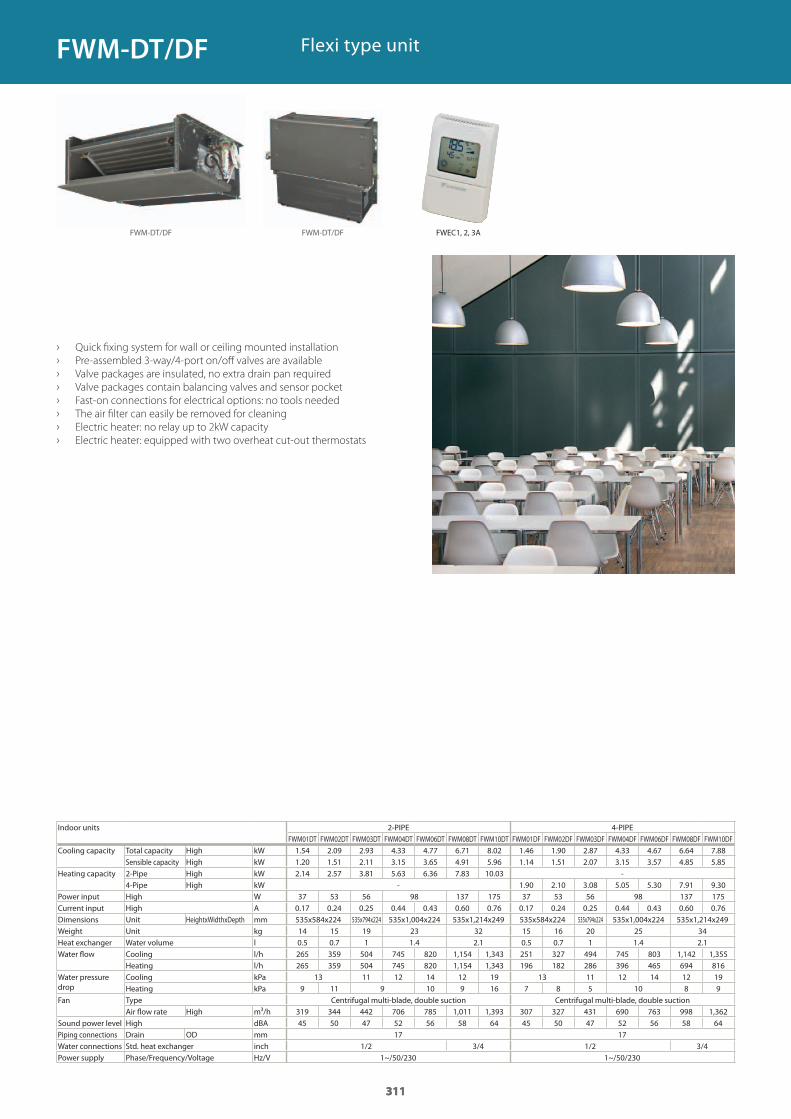
311
Indoor units 2-PIPE 4-PIPE
Cooling capacity Total capacity High kWSensible capacity High kW
Heating capacity 2-Pipe High kW4-Pipe High kW
Power input High WCurrent input High ADimensions Unit HeightxWidthxDepth mmWeight Unit kgHeat exchanger Water volume lWater flow Cooling l/h
Heating l/hWater pressure drop
Cooling kPaHeating kPa
Fan Type Centrifugal multi-blade, double suction Centrifugal multi-blade, double suctionAir flow rate High m³/h
Sound power level High dBAPiping connections Drain OD mmWater connections Std. heat exchanger inchPower supply Phase/Frequency/Voltage Hz/V
› Quick fixing system for wall or ceiling mounted installation
› Pre-assembled 3-way/4-port on/off valves are available
› Valve packages are insulated, no extra drain pan required
› Valve packages contain balancing valves and sensor pocket
› Fast-on connections for electrical options: no tools needed
› The air filter can easily be removed for cleaning
› Electric heater: no relay up to 2kW capacity
› Electric heater: equipped with two overheat cut-out thermostats
Flexi type unit
311
FWM01DT FWM02DT FWM03DT FWM04DT FWM06DT FWM08DT FWM10DT FWM01DF FWM02DF FWM03DF FWM04DF FWM06DF FWM08DF FWM10DF1.54 2.09 2.93 4.33 4.77 6.71 8.02 1.46 1.90 2.87 4.33 4.67 6.64 7.88 1.20 1.51 2.11 3.15 3.65 4.91 5.96 1.14 1.51 2.07 3.15 3.57 4.85 5.85 2.14 2.57 3.81 5.63 6.36 7.83 10.03 -
- 1.90 2.10 3.08 5.05 5.30 7.91 9.30 37 53 56 98 137 175 37 53 56 98 137 1750.17 0.24 0.25 0.44 0.43 0.60 0.76 0.17 0.24 0.25 0.44 0.43 0.60 0.76535x584x224 535x794x224 535x1,004x224 535x1,214x249 535x584x224 535x794x224 535x1,004x224 535x1,214x24914 15 19 23 32 15 16 20 25 340.5 0.7 1 1.4 2.1 0.5 0.7 1 1.4 2.1265 359 504 745 820 1,154 1,343 251 327 494 745 803 1,142 1,355265 359 504 745 820 1,154 1,343 196 182 286 396 465 694 816
13 11 12 14 12 19 13 11 12 14 12 199 11 9 10 9 16 7 8 5 10 8 9
319 344 442 706 785 1,011 1,393 307 327 431 690 763 998 1,36245 50 47 52 56 58 64 45 50 47 52 56 58 64
17 171/2 3/4 1/2 3/4
1~/50/230 1~/50/230
311
FWM-DT/DF FWM-DT/DF
FWM-DT/DF
FWEC1, 2, 3A
GC_pre2_lowres.pdf 311 30/11/2011 12:32:01
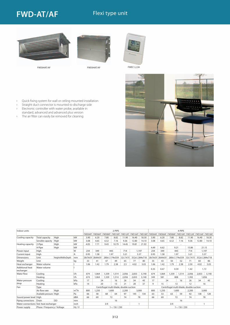
Flexi type unit
› Quick fixing system for wall or ceiling mounted installation
› Straight duct connector is mounted to discharge side
› Electronic controller with water probe, available in
standard, advanced and advanced plus version
› The air filter can easily be removed for cleaning
Indoor units 2-PIPE 4-PIPEFWD04AT FWD06AT FWD08AT FWD10AT FWD12AT FWD16AT FWD18AT FWD04AF FWD06AF FWD08AF FWD10AF FWD12AF FWD16AF FWD18AF
Cooling capacity Total capacity High kWSensible capacity High kW
Heating capacity 2-Pipe High kW4-Pipe High kW
Power input High WCurrent input High ADimensions Unit HeightxWidthxDepth mmWeight Unit kgHeat exchanger Water volume lAdditional heat exchanger
Water volume l
Water flow Cooling l/hHeating l/h
Water pressure drop
Cooling kPaHeating kPa
Fan Type Centrifugal multi-blade, double suction Centrifugal multi-blade, double suctionAir flow rate High m³/hAvailable pressure High Pa
Sound power level High dBAPiping connections Drain OD mmWater connections Std. heat exchanger inchPower supply Phase / Frequency / Voltage Hz / V
3.90 6.20 7.80 8.82 11.90 16.40 18.30 3.90 6.20 7.80 8.82 11.90 16.40 18.303.08 4.65 6.52 7.16 9.36 12.80 14.10 3.08 4.65 6.52 7.16 9.36 12.80 14.104.05 7.71 9.43 10.79 14.45 19.81 21.92 -
- 4.49 6.62 9.21 15.86 21.15234 349 443 714 1,197 234 349 443 714 1,1970.95 1.58 1.97 3.21 5.37 0.95 1.58 1.97 3.21 5.37
280x754x559 280x964x559 280x1,174x559 352x1,174x718 352x1,384x718 280x754x559 280x964x559 280x1,174x559 352x1,174x718 352x1,384x71833 41 47 49 65 77 80 35 43 50 52 71 83 86
1.06 1.42 1.79 2.38 2.5 4.02 5.03 1.06 1.42 1.79 2.38 2.50 4.02 5.03
- 0.35 0.47 0.59 1.42 1.72
674 1,064 1,339 1,514 2,056 2,833 3,140 674 1,064 1,339 1,514 2,056 2,833 3,140674 1,064 1,339 1,514 2,056 2,833 3,140 349 581 808 1,392 1,85617 24 16 26 34 45 17 24 16 26 34 4514 20 13 21 28 37 9 15 13 12 16
800 1,250 1,600 2,200 3,000 800 1,250 1,600 2,200 3,00066 58 68 64 97 145 134 63 53 63 59 92 138 12866 69 72 74 78 66 69 72 74 78
16 163/4 1 3/4 1
1~ / 50 / 230 1~ / 50 / 230
312
FWD-AT/AF
FWD04AT/AFFWD04AT/AF FWEC1,2,3A
GC_pre2_lowres.pdf 312 30/11/2011 12:32:01
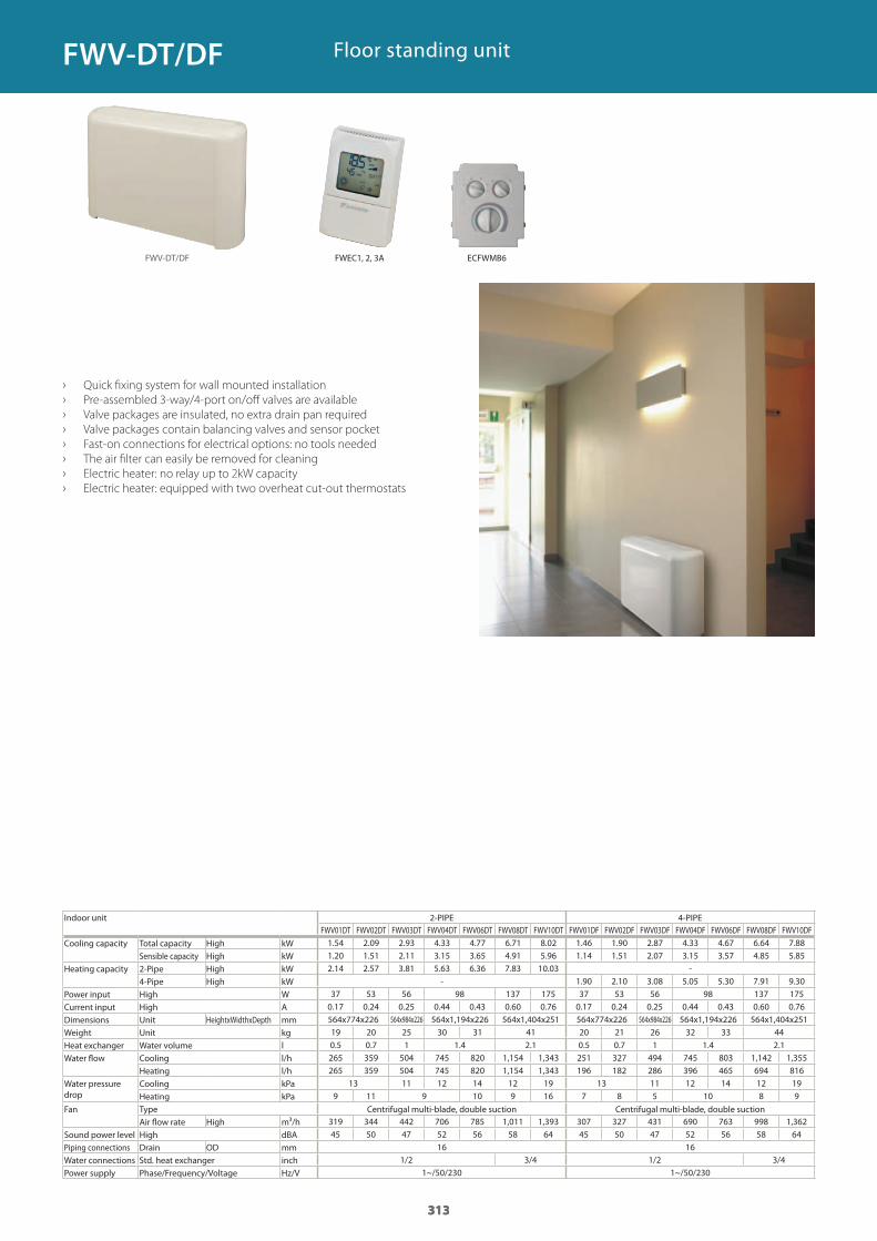
313
Indoor unit 2-PIPE 4-PIPE
Cooling capacity Total capacity High kWSensible capacity High kW
Heating capacity 2-Pipe High kW4-Pipe High kW
Power input High WCurrent input High ADimensions Unit HeightxWidthxDepth mmWeight Unit kgHeat exchanger Water volume lWater flow Cooling l/h
Heating l/hWater pressure drop
Cooling kPaHeating kPa
Fan Type Centrifugal multi-blade, double suction Centrifugal multi-blade, double suctionAir flow rate High m³/h
Sound power level High dBAPiping connections Drain OD mmWater connections Std. heat exchanger inchPower supply Phase/Frequency/Voltage Hz/V
› Quick fixing system for wall mounted installation
› Pre-assembled 3-way/4-port on/off valves are available
› Valve packages are insulated, no extra drain pan required
› Valve packages contain balancing valves and sensor pocket
› Fast-on connections for electrical options: no tools needed
› The air filter can easily be removed for cleaning
› Electric heater: no relay up to 2kW capacity
› Electric heater: equipped with two overheat cut-out thermostats
Floor standing unit
313
FWV01DT FWV02DT FWV03DT FWV04DT FWV06DT FWV08DT FWV10DT FWV01DF FWV02DF FWV03DF FWV04DF FWV06DF FWV08DF FWV10DF1.54 2.09 2.93 4.33 4.77 6.71 8.02 1.46 1.90 2.87 4.33 4.67 6.64 7.88 1.20 1.51 2.11 3.15 3.65 4.91 5.96 1.14 1.51 2.07 3.15 3.57 4.85 5.85 2.14 2.57 3.81 5.63 6.36 7.83 10.03 -
- 1.90 2.10 3.08 5.05 5.30 7.91 9.30 37 53 56 98 137 175 37 53 56 98 137 1750.17 0.24 0.25 0.44 0.43 0.60 0.76 0.17 0.24 0.25 0.44 0.43 0.60 0.76564x774x226 564x984x226 564x1,194x226 564x1,404x251 564x774x226 564x984x226 564x1,194x226 564x1,404x25119 20 25 30 31 41 20 21 26 32 33 440.5 0.7 1 1.4 2.1 0.5 0.7 1 1.4 2.1265 359 504 745 820 1,154 1,343 251 327 494 745 803 1,142 1,355265 359 504 745 820 1,154 1,343 196 182 286 396 465 694 816
13 11 12 14 12 19 13 11 12 14 12 199 11 9 10 9 16 7 8 5 10 8 9
319 344 442 706 785 1,011 1,393 307 327 431 690 763 998 1,36245 50 47 52 56 58 64 45 50 47 52 56 58 64
16 161/2 3/4 1/2 3/4
1~/50/230 1~/50/230
313
FWV-DT/DF
FWV-DT/DF
ECFWMB6FWEC1, 2, 3A
GC_pre2_lowres.pdf 313 30/11/2011 12:32:01
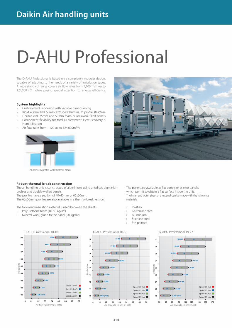
314
174
The D-AHU Professional is based on a completely modular design,
capable of adapting to the needs of a variety of installation types.
A wide standard range covers air fl ow rates from 1,100m³/h up to
124,000m³/h while paying special attention to energy effi ciency.
System highlights
› Custom modular design with variable dimensioning
› Rigid 40mm and 60mm extruded aluminium profile structure
› Double wall 25mm and 50mm foam or rockwool filled panels
› Component flexibility for total air treatment: Heat Recovery &
Humidification
› Air flow rates from 1,100 up to 124,000m3/h
Robust thermal-break construction
The air handling unit is constructed of aluminium, using anodised aluminium
profi les and double-walled panels.
The profi les have a section of 40x40mm or 60x60mm.
The 60x60mm profi les are also available in a thermal-break version.
The following insulation material is used between the sheets:
› Polyurethane foam (40-50 kg/m3)
› Mineral wool, glued to the panel (90 kg/m3)
The panels are available as fl at panels or as step panels,
which permit to obtain a fl at surface inside the unit.
The inner and outer sheet of the panel can be made with the following
materials:
› Plastisol
› Galvanised steel
› Aluminium
› Stainless steel
› Pre-painted
D-AHU Professional
D-AHU Professional 01-09
Air flow rate (m3/h) x 1,000
Mo
de
l si
ze
Speed 2.0 m/s
Speed 3.0 m/s
Speed 2.5 m/s
Speed 3.5 m/s
D-AHU Professional 10-18
Mo
de
l si
ze
Air flow rate (m3/h) x 1,000
D-AHU Professional 19-27
Air flow rate (m3/h) x 1,000
Speed 2.0 m/s
Speed 3.0 m/s
Speed 2.5 m/s
Speed 3.5 m/s
Speed 2.0 m/s
Speed 3.0 m/s
Speed 2.5 m/s
Speed 3.5 m/s
Daikin Air handling units
Aluminium profile with thermal break
Mo
de
l si
ze
GC_pre2_lowres.pdf 314 30/11/2011 12:32:02
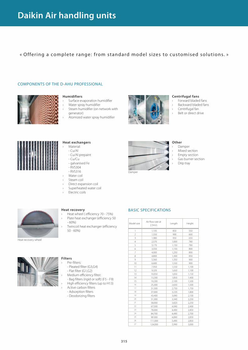
315
1 1,105 850 550
2 1,550 900 600
3 1,980 950 650
4 2,570 1,000 780
5 3,170 1,150 780
6 3,550 1,150 800
7 4,000 1,250 800
8 4,800 1,300 850
9 5,560 1,350 900
10 6,600 1,550 900
11 7,950 1,550 1,100
12 9,320 1,650 1,100
13 10,050 1,650 1,150
14 13,200 1,850 1,400
15 19,200 2,100 1,500
16 25,300 2,650 1,500
17 31,500 2,750 1,750
18 37,000 3,220 1,800
19 43,400 3,090 2,100
20 51,300 3,340 2,250
21 58,000 3,820 2,250
22 67,500 4,040 2,400
23 78,000 4,490 2,450
24 84,700 4,490 2,700
25 98 000 4,890 2,850
26 111,000 5,490 2,850
27 124,000 5,990 3,000
Daikin Air handling units
Damper
Heat recovery wheel
Humidifiers
› Surface evaporation humidifier
› Water spray humidifier
› Steam humidifier (on network with
generator)
› Atomized water spray humidifier
Heat recovery
› Heat wheel ( efficiency 70 - 75%)
› Plate heat exchanger (efficiency 50
- 60%)
› Twincoil heat exchanger (efficiency
50 - 60%)
Filters
› Pre-filters:
- Pleated filter (G3,G4)
- Flat filter (G1,G2)
› Medium efficiency filter:
- Bag filters (rigid or soft) (F5 - F9)
› High efficiency filters (up to H13)
› Active carbon filters
- Adsorption filters
- Deodorizing filters
Heat exchangers
› Material:
- Cu/Al
- Cu/Al prepaint
- Cu/Cu
- galvanised Fe
- RVS304
- RVS316
› Water coil
› Steam coil
› Direct expansion coil
› Superheated water coil
› Electric coils
Centrifugal fans
› Forward bladed fans
› Backward bladed fans
› Centrifugal fan
› Belt or direct drive
Other
› Damper
› Mixed section
› Empty section
› Gas burner section
› Drip tray
COMPONENTS OF THE D-AHU PROFESSIONAL
« Offer ing a comp lete range: f rom standard mode l s izes to customised so lu t ions. »
BASIC SPECIFICATIONS
Model sizeAir fl ow rate at
2.5m/sLength Height
GC_pre2_lowres.pdf 315 30/11/2011 12:32:02
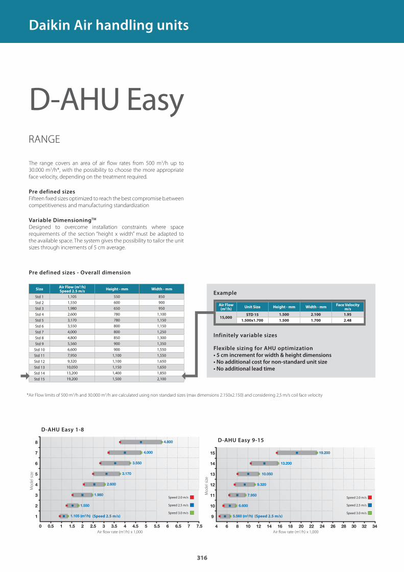
316316316
0
1
2
3
4
5
6
7
8
0.5 1 1.5 2 2.5 3 3.5 4 4.5 5 5.5 6 6.5 7 7.5
1.105 (m3/h)
1.550
1.980
2.600
3.170
3.550
4.000
4.800
4
9
10
11
12
13
14
15
6 8 10 12 14 16 18 20 22 24 26 28 30 32 34
5.560 (m3/h)
6.600
7.950
9.320
10.050
13.200
19.200
1,105 550 850
1,550 600 900
1,980 650 950
2,600 780 1,100
3,170 780 1,150
3,550 800 1,150
4,000 800 1,250
4,800 850 1,300
5,560 900 1,350
6,600 900 1,550
7,950 1,100 1,550
9,320 1,100 1,650
10,050 1,150 1,650
13,200 1,400 1,850
19,200 1,500 2,100
15,0001.500 2.100 1.95
1.500x1.700 1.500 1.700 2.48
RANGE
The range covers an area of air fl ow rates from 500 m3/h up to
30.000 m3/h*, with the possibility to choose the more appropriate
face velocity, depending on the treatment required.
Pre defined sizes
Fifteen fi xed sizes optimized to reach the best compromise b.etween
competitiveness and manufacturing standardization
Variable DimensioningTM
Designed to overcome installation constraints where space
requirements of the section “height x width” must be adapted to
the available space. The system gives the possibility to tailor the unit
sizes through increments of 5 cm average.
Pre defined sizes - Overall dimension
D-AHU Easy
Daikin Air handling units
*Air Flow limits of 500 m3/h and 30.000 m3/h are calculated using non standard sizes (max dimensions 2.150x2.150) and considering 2,5 m/s coil face velocity
D-AHU Easy 1-8
D-AHU Easy 9-15
Flexible sizing for AHU optimization
• 5 cm increment for width & height dimensions
• No additional cost for non-standard unit size
• No additional lead time
Infinitely variable sizes
Example
Air flow rate (m3/h) x 1,000Air flow rate (m3/h) x 1,000
Mo
de
l si
ze
Mo
de
l si
ze
(Speed 2.5 m/s)(Speed 2.5 m/s)
Speed 2.0 m/s
Speed 3.0 m/s
Speed 2.5 m/s
Speed 2.0 m/s
Speed 3.0 m/s
Speed 2.5 m/s
SizeAir Flow (m3/h)Speed 2.5 m/s
Height - mm Width - mm
Std 1
Std 2
Std 3
Std 4
Std 5
Std 6
Std 7
Std 8
Std 9
Std 10
Std 11
Std 12
Std 13
Std 14
Std 15
Air Flow (m3/h)
Unit Size Height - mm Width - mmFace Velocity
m/s
STD 15
GC_pre2_lowres.pdf 316 30/11/2011 12:32:02
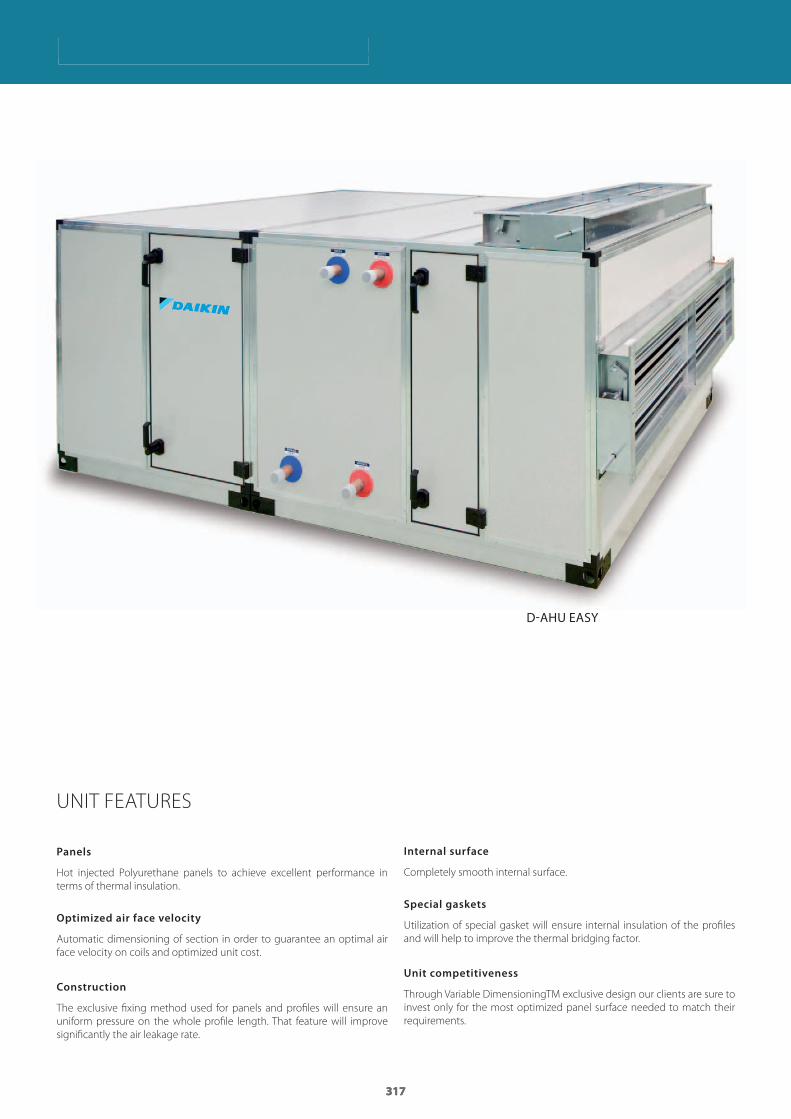
317317317
Daikin Air handling unitsDaikin Air handling units
UNIT FEATURES
Panels
Hot injected Polyurethane panels to achieve excellent performance in
terms of thermal insulation.
Optimized air face velocity
Automatic dimensioning of section in order to guarantee an optimal air
face velocity on coils and optimized unit cost.
Construction
The exclusive fi xing method used for panels and profi les will ensure an
uniform pressure on the whole profi le length. That feature will improve
signifi cantly the air leakage rate.
Internal surface
Completely smooth internal surface.
Special gaskets
Utilization of special gasket will ensure internal insulation of the profi les
and will help to improve the thermal bridging factor.
Unit competitiveness
Through Variable DimensioningTM exclusive design our clients are sure to
invest only for the most optimized panel surface needed to match their
requirements.
D-AHU EASY
GC_pre2_lowres.pdf 317 30/11/2011 12:32:02

GC_pre2_lowres.pdf 318 30/11/2011 12:32:02
319
Daikin offers a wide range of condensing units for medium and low temperature refrigeration applications. Daikin refrigeration units combine efficiency and reliability with easy installation and maintenance.
,�),.9�, 2.6�Conveni-pack 320ZEAS condensing units 324Commercial condensing units 326Large variable capacity condensing unit 327
GC_pre2_lowres.pdf 319 30/11/2011 12:32:03

320
CONVENIPACK IS A COMPACT, LOW NOISE SYSTEM
WHICH INTEGRATES HIGH AND LOW TEMPERATURE
REFRIGERATION AND AIR CONDITIONING
INCLUDING HEATING INTO ONE SYSTEM.
Helping retailers save energy and the environmentRetailers are faced with a growing need for fresh goods,
prepared meals and chilled drinks. At the same time,
environmental and zoning requirements are stricter than ever,
and energy costs must be kept under control. Conveni-pack
minimises total energy demand due to its unique, integrated
approach to refrigeration and air conditioning.
A total solutionfor small applicationsConveni-pack is unique in combining refrigeration and air
conditioning equipment in one total solution using the
latest controls and inverter technology in order to maximize
energy effi ciency. The system can be connected to basically
all refrigeration applications and is supplied with a wide
range of air conditioning indoor units to respond to all shop
requirements. An optional booster unit is available for low
temperature refrigeration.
Conveni-pack
GC_pre2_lowres.pdf 320 30/11/2011 12:32:03
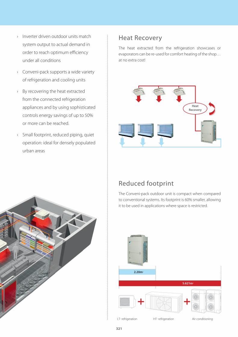
321
› Inverter driven outdoor units match
system output to actual demand in
order to reach optimum effi ciency
under all conditions
› Conveni-pack supports a wide variety
of refrigeration and cooling units
› By recovering the heat extracted
from the connected refrigeration
appliances and by using sophisticated
controls energy savings of up to 50%
or more can be reached.
› Small footprint, reduced piping, quiet
operation: ideal for densely populated
urban areas
Heat RecoveryThe heat extracted from the refrigeration showcases or
evaporators can be re-used for comfort heating of the shop…
at no extra cost!
Reduced footprintThe Conveni-pack outdoor unit is compact when compared
to conventional systems. Its footprint is 60% smaller, allowing
it to be used in applications where space is restricted.
Heat
Recovery
LT1 refrigeration HT2 refrigeration Air conditioning
5.621m2
2.20m2
GC_pre2_lowres.pdf 321 30/11/2011 12:32:04
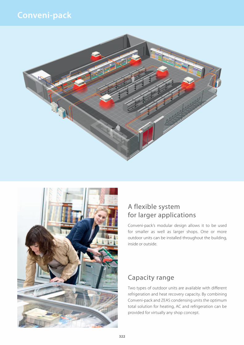
322
A flexible system for larger applicationsConveni-pack’s modular design allows it to be used
for smaller as well as larger shops. One or more
outdoor units can be installed throughout the building,
inside or outside.
Capacity rangeTwo types of outdoor units are available with different
refrigeration and heat recovery capacity. By combining
Conveni-pack and ZEAS condensing units the optimum
total solution for heating, AC and refrigeration can be
provided for virtually any shop concept.
Conveni-pack
GC_pre2_lowres.pdf 322 30/11/2011 12:32:04
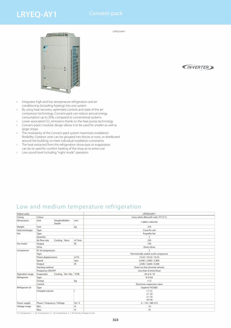
323
Low and medium temperature refrigerationIndoor units LRYEQ16AY1Casing Colour Ivory white (Munsell code: 5Y7.5/1)Dimensions Unit HeightxWidthx
Depthmm
Weight Unit kgHeat exchanger Type Cross fin coilFan Type Propeller fan
QuantityAir flow rate Cooling Nom. m³/min
Fan motor Output WDrive Direct drive
Compressor N° of compressors 3Type Hermetically sealed scroll compressorPiston displacement m³/hSpeed rpmOutput WStarting method Direct on line (inverter driven)Frequency ON/OFF Less than 6 times/hour
Operation range Evaporator Cooling Min.~Max. °CDBRefrigerant Type R-410A
Charge kgControl Electronic expansion valve
Refrigerant oil Type Daphne FVC68DCharged volume l
Power supply Phase / Frequency / Voltage Hz / VVoltage range Min. %
Max. %
› Integrates high and low temperature refrigeration and air
conditioning (including heating) into one system
› By using heat recovery, optimised controls and state of the art
compressor technology, Conveni-pack can reduce annual energy
consumption up to 50%, compared to conventional systems
› Lower associated CO2 emissions thanks to the heat pump technology
› Conveni-pack’s modular design allows it to be used for smaller as well as
larger shops
› The modularity of the Conveni-pack system maximises installation
flexibility. Outdoor units can be grouped into blocks or rows, or distributed
around the building, to meet individual installation constraints
› The heat extracted from the refrigeration showcases or evaporators
can be re-used for comfort heating of the shop at no extra cost
› Low sound level including "night mode" operation
Conveni-pack
(1) Compressor 1 | (2) Compressor 2 | (3) Compressor 3 | (4) Factory charge of unit
323
1,680x1,240x765
370
2230750
13.34 / 10.53 / 10.536,300 / 2,900 / 2,9002,500 / 3,600 / 4,500
-20 @ 0~10
11.5
1.7 (1) 2.1 (2) 2.1 (3) 4.0 (4)
3~ / 50 / 380-415-1010
323
LRYEQ16AY1
LRYEQ-AY1
GC_pre2_lowres.pdf 323 30/11/2011 12:32:04
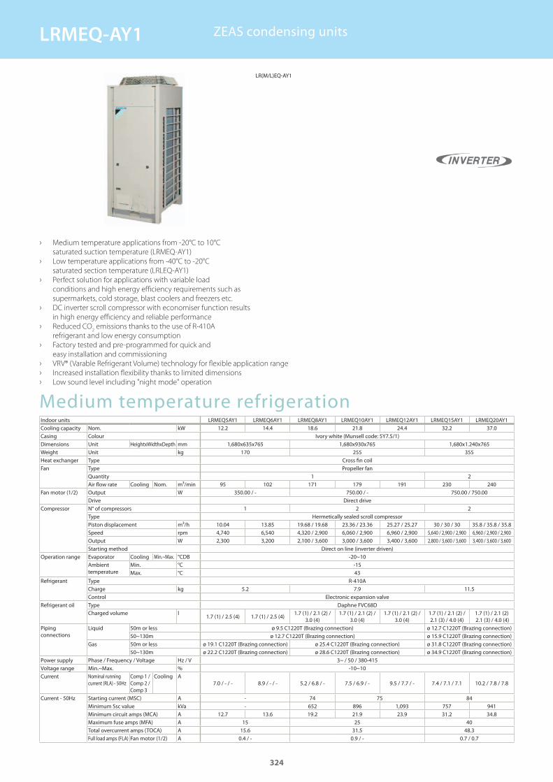
Medium temperature refrigerationIndoor units LRMEQ5AY1 LRMEQ6AY1 LRMEQ8AY1 LRMEQ10AY1 LRMEQ12AY1 LRMEQ15AY1 LRMEQ20AY1Cooling capacity Nom. kWCasing Colour Ivory white (Munsell code: 5Y7.5/1)Dimensions Unit HeightxWidthxDepth mmWeight Unit kgHeat exchanger Type Cross fin coilFan Type Propeller fan
QuantityAir flow rate Cooling Nom. m³/min
Fan motor (1/2) Output WDrive Direct drive
Compressor N° of compressorsType Hermetically sealed scroll compressorPiston displacement m³/hSpeed rpmOutput WStarting method Direct on line (inverter driven)
Operation range Evaporator Cooling Min.~Max. °CDBAmbient temperature
Min. °CMax. °C
Refrigerant Type R-410ACharge kgControl Electronic expansion valve
Refrigerant oil Type Daphne FVC68DCharged volume l
Piping connections
Liquid 50m or less ø 9.5 C1220T (Brazing connection) ø 12.7 C1220T (Brazing connection)50~130m ø 12.7 C1220T (Brazing connection) ø 15.9 C1220T (Brazing connection)
Gas 50m or less ø 19.1 C1220T (Brazing connection) ø 25.4 C1220T (Brazing connection) ø 31.8 C1220T (Brazing connection)50~130m ø 22.2 C1220T (Brazing connection) ø 28.6 C1220T (Brazing connection) ø 34.9 C1220T (Brazing connection)
Power supply Phase / Frequency / Voltage Hz / VVoltage range Min.~Max. %Current Nominal running
current (RLA) - 50HzComp 1 / Comp 2 / Comp 3
Cooling A
Current - 50Hz Starting current (MSC) AMinimum Ssc value kVaMinimum circuit amps (MCA) AMaximum fuse amps (MFA) ATotal overcurrent amps (TOCA) AFull load amps (FLA) Fan motor (1/2) A
› Medium temperature applications from -20°C to 10°C
saturated suction temperature (LRMEQ-AY1)
› Low temperature applications from -40°C to -20°C
saturated section temperature (LRLEQ-AY1)
› Perfect solution for applications with variable load
conditions and high energy efficiency requirements such as
supermarkets, cold storage, blast coolers and freezers etc.
› DC inverter scroll compressor with economiser function results
in high energy efficiency and reliable performance
› Reduced CO2 emissions thanks to the use of R-410A
refrigerant and low energy consumption
› Factory tested and pre-programmed for quick and
easy installation and commissioning
› VRV® (Varable Refrigerant Volume) technology for flexible application range
› Increased installation flexibility thanks to limited dimensions
› Low sound level including "night mode" operation
ZEAS condensing units
12.2 14.4 18.6 21.8 24.4 32.2 37.0
1,680x635x765 1,680x930x765 1,680x1.240x765170 255 355
1 295 102 171 179 191 230 240
350.00 / - 750.00 / - 750.00 / 750.00
1 2 2
10.04 13.85 19.68 / 19.68 23.36 / 23.36 25.27 / 25.27 30 / 30 / 30 35.8 / 35.8 / 35.84,740 6,540 4,320 / 2,900 6,060 / 2,900 6,960 / 2,900 5,640 / 2,900 / 2,900 6,960 / 2,900 / 2,9002,300 3,200 2,100 / 3,600 3,000 / 3,600 3,400 / 3,600 2,800 / 3,600 / 3,600 3,400 / 3,600 / 3,600
-20~10-1543
5.2 7.9 11.5
1.7 (1) / 2.5 (4) 1.7 (1) / 2.5 (4)1.7 (1) / 2.1 (2) /
3.0 (4)1.7 (1) / 2.1 (2) /
3.0 (4)1.7 (1) / 2.1 (2) /
3.0 (4)1.7 (1) / 2.1 (2) / 2.1 (3) / 4.0 (4)
1.7 (1) / 2.1 (2) 2.1 (3) / 4.0 (4)
3~ / 50 / 380-415-10~10
7.0 / - / - 8.9 / - / - 5.2 / 6.8 / - 7.5 / 6.9 / - 9.5 / 7.7 / - 7.4 / 7.1 / 7.1 10.2 / 7.8 / 7.8
- 74 75 84- 652 896 1,093 757 941
12.7 13.6 19.2 21.9 23.9 31.2 34.815 25 40
15.6 31.5 48.30.4 / - 0.9 / - 0.7 / 0.7
324
LR(M/L)EQ-AY1
LRMEQ-AY1
GC_pre2_lowres.pdf 324 30/11/2011 12:32:05
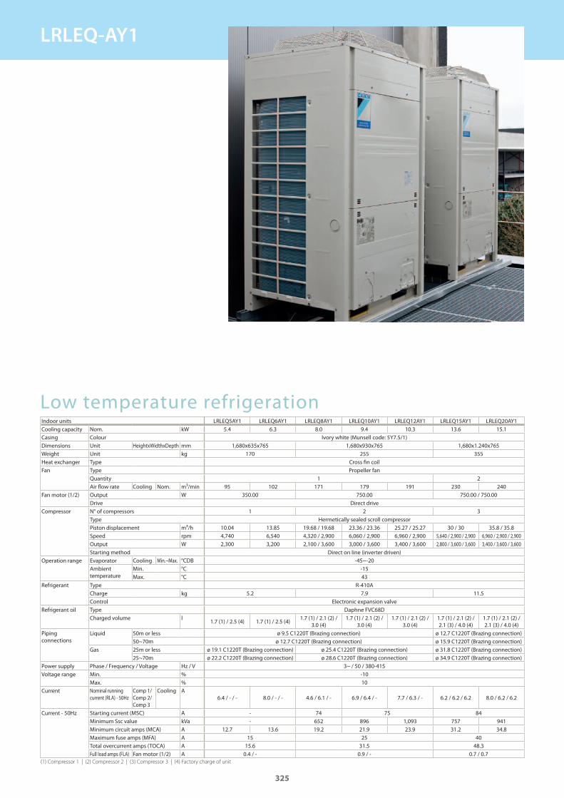
Low temperature refrigerationIndoor units LRLEQ5AY1 LRLEQ6AY1 LRLEQ8AY1 LRLEQ10AY1 LRLEQ12AY1 LRLEQ15AY1 LRLEQ20AY1Cooling capacity Nom. kWCasing Colour Ivory white (Munsell code: 5Y7.5/1)Dimensions Unit HeightxWidthxDepth mmWeight Unit kgHeat exchanger Type Cross fi n coilFan Type Propeller fan
QuantityAir fl ow rate Cooling Nom. m³/min
Fan motor (1/2) Output WDrive Direct drive
Compressor N° of compressorsType Hermetically sealed scroll compressorPiston displacement m³/hSpeed rpmOutput WStarting method Direct on line (inverter driven)
Operation range Evaporator Cooling Min.~Max. °CDBAmbient temperature
Min. °CMax. °C
Refrigerant Type R-410ACharge kgControl Electronic expansion valve
Refrigerant oil Type Daphne FVC68DCharged volume l
Piping connections
Liquid 50m or less ø 9.5 C1220T (Brazing connection) ø 12.7 C1220T (Brazing connection)50~70m ø 12.7 C1220T (Brazing connection) ø 15.9 C1220T (Brazing connection)
Gas 25m or less ø 19.1 C1220T (Brazing connection) ø 25.4 C1220T (Brazing connection) ø 31.8 C1220T (Brazing connection)25~70m ø 22.2 C1220T (Brazing connection) ø 28.6 C1220T (Brazing connection) ø 34.9 C1220T (Brazing connection)
Power supply Phase / Frequency / Voltage Hz / VVoltage range Min. %
Max. %Current Nominal running
current (RLA) - 50HzComp 1/ Comp 2/ Comp 3
Cooling A
Current - 50Hz Starting current (MSC) AMinimum Ssc value kVaMinimum circuit amps (MCA) AMaximum fuse amps (MFA) ATotal overcurrent amps (TOCA) AFull load amps (FLA) Fan motor (1/2) A
(1) Compressor 1 | (2) Compressor 2 | (3) Compressor 3 | (4) Factory charge of unit
5.4 6.3 8.0 9.4 10.3 13.6 15.1
1,680x635x765 1,680x930x765 1,680x1.240x765170 255 355
1 295 102 171 179 191 230 240
350.00 750.00 750.00 / 750.00
1 2 3
10.04 13.85 19.68 / 19.68 23.36 / 23.36 25.27 / 25.27 30 / 30 35.8 / 35.84,740 6,540 4,320 / 2,900 6,060 / 2,900 6,960 / 2,900 5,640 / 2,900 / 2,900 6,960 / 2,900 / 2,9002,300 3,200 2,100 / 3,600 3,000 / 3,600 3,400 / 3,600 2,800 / 3,600 / 3,600 3,400 / 3,600 / 3,600
-45~-20-1543
5.2 7.9 11.5
1.7 (1) / 2.5 (4) 1.7 (1) / 2.5 (4)1.7 (1) / 2.1 (2) /
3.0 (4)1.7 (1) / 2.1 (2) /
3.0 (4)1.7 (1) / 2.1 (2) /
3.0 (4)1.7 (1) / 2.1 (2) / 2.1 (3) / 4.0 (4)
1.7 (1) / 2.1 (2) / 2.1 (3) / 4.0 (4)
3~ / 50 / 380-415-1010
6.4 / - / - 8.0 / - / - 4.6 / 6.1 / - 6.9 / 6.4 / - 7.7 / 6.3 / - 6.2 / 6.2 / 6.2 8.0 / 6.2 / 6.2
- 74 75 84- 652 896 1,093 757 941
12.7 13.6 19.2 21.9 23.9 31.2 34.815 25 40
15.6 31.5 48.30.4 / - 0.9 / - 0.7 / 0.7
325
LRLEQ-AY1
GC_pre2_lowres.pdf 325 30/11/2011 12:32:05
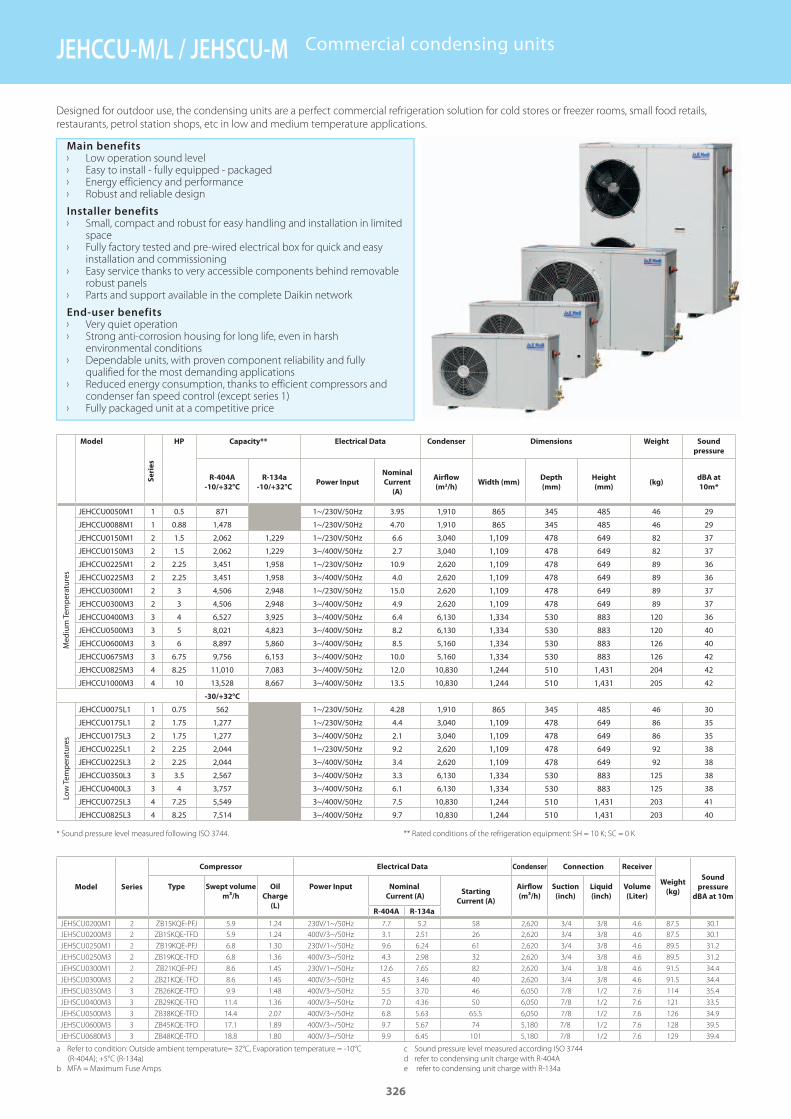
Model
Se
rie
s
HP Capacity** Electrical Data Condenser Dimensions Weight Sound
pressure
R-404A
-10/+32°C
R-134a
-10/+32°CPower Input
Nominal
Current
(A)
Airfl ow
(m3/h)Width (mm)
Depth
(mm)
Height
(mm)(kg)
dBA at
10m*
Med
ium
Tem
perat
ures
Low
Tem
perat
ures
* Sound pressure level measured following ISO 3744. ** Rated conditions of the refrigeration equipment: SH = 10 K; SC = 0 K
Designed for outdoor use, the condensing units are a perfect commercial refrigeration solution for cold stores or freezer rooms, small food retails,
restaurants, petrol station shops, etc in low and medium temperature applications.
Main benefits › Low operation sound level › Easy to install - fully equipped - packaged › Energy efficiency and performance › Robust and reliable design
Installer benefits › Small, compact and robust for easy handling and installation in limited
space › Fully factory tested and pre-wired electrical box for quick and easy
installation and commissioning › Easy service thanks to very accessible components behind removable
robust panels › Parts and support available in the complete Daikin network
End-user benefits › Very quiet operation › Strong anti-corrosion housing for long life, even in harsh
environmental conditions › Dependable units, with proven component reliability and fully
qualified for the most demanding applications › Reduced energy consumption, thanks to efficient compressors and
condenser fan speed control (except series 1) › Fully packaged unit at a competitive price
Commercial condensing units
a Refer to condition: Outside ambient temperature= 32°C, Evaporation temperature = -10°C
(R-404A); +5°C (R-134a)
b MFA = Maximum Fuse Amps
c Sound pressure level measured according ISO 3744
d refer to condensing unit charge with R-404A
e refer to condensing unit charge with R-134a
Model Series
Compressor Electrical Data Condenser Connection Receiver
Weight
(kg)
Sound
pressure
dBA at 10m
Type Swept volume
m³/h
Oil
Charge
(L)
Power Input Nominal
Current (A)Starting
Current (A)
Airflow
(m³/h)
Suction
(inch)
Liquid
(inch)
Volume
(Liter)
R-404A R-134a
JEHSCU0200M1 2 ZB15KQE-PFJ 5.9 1.24 230V/1~/50Hz 7.7 5.2 58 2,620 3/4 3/8 4.6 87.5 30.1
JEHSCU0200M3 2 ZB15KQE-TFD 5.9 1.24 400V/3~/50Hz 3.1 2.51 26 2,620 3/4 3/8 4.6 87.5 30.1
JEHSCU0250M1 2 ZB19KQE-PFJ 6.8 1.30 230V/1~/50Hz 9.6 6.24 61 2,620 3/4 3/8 4.6 89.5 31.2
JEHSCU0250M3 2 ZB19KQE-TFD 6.8 1.36 400V/3~/50Hz 4.3 2.98 32 2,620 3/4 3/8 4.6 89.5 31.2
JEHSCU0300M1 2 ZB21KQE-PFJ 8.6 1.45 230V/1~/50Hz 12.6 7.65 82 2,620 3/4 3/8 4.6 91.5 34.4
JEHSCU0300M3 2 ZB21KQE-TFD 8.6 1.45 400V/3~/50Hz 4.5 3.46 40 2,620 3/4 3/8 4.6 91.5 34.4
JEHSCU0350M3 3 ZB26KQE-TFD 9.9 1.48 400V/3~/50Hz 5.5 3.70 46 6,050 7/8 1/2 7.6 114 35.4
JEHSCU0400M3 3 ZB29KQE-TFD 11.4 1.36 400V/3~/50Hz 7.0 4.36 50 6,050 7/8 1/2 7.6 121 33.5
JEHSCU0500M3 3 ZB38KQE-TFD 14.4 2.07 400V/3~/50Hz 6.8 5.63 65.5 6,050 7/8 1/2 7.6 126 34.9
JEHSCU0600M3 3 ZB45KQE-TFD 17.1 1.89 400V/3~/50Hz 9.7 5.67 74 5,180 7/8 1/2 7.6 128 39.5
JEHSCU0680M3 3 ZB48KQE-TFD 18.8 1.80 400V/3~/50Hz 9.9 6.45 101 5,180 7/8 1/2 7.6 129 39.4
JEHCCU0050M1 1 0.5 871 - 1~/230V/50Hz 3.95 1,910 865 345 485 46 29
JEHCCU0088M1 1 0.88 1,478 - 1~/230V/50Hz 4.70 1,910 865 345 485 46 29
JEHCCU0150M1 2 1.5 2,062 1,229 1~/230V/50Hz 6.6 3,040 1,109 478 649 82 37
JEHCCU0150M3 2 1.5 2,062 1,229 3~/400V/50Hz 2.7 3,040 1,109 478 649 82 37
JEHCCU0225M1 2 2.25 3,451 1,958 1~/230V/50Hz 10.9 2,620 1,109 478 649 89 36
JEHCCU0225M3 2 2.25 3,451 1,958 3~/400V/50Hz 4.0 2,620 1,109 478 649 89 36
JEHCCU0300M1 2 3 4,506 2,948 1~/230V/50Hz 15.0 2,620 1,109 478 649 89 37
JEHCCU0300M3 2 3 4,506 2,948 3~/400V/50Hz 4.9 2,620 1,109 478 649 89 37
JEHCCU0400M3 3 4 6,527 3,925 3~/400V/50Hz 6.4 6,130 1,334 530 883 120 36
JEHCCU0500M3 3 5 8,021 4,823 3~/400V/50Hz 8.2 6,130 1,334 530 883 120 40
JEHCCU0600M3 3 6 8,897 5,860 3~/400V/50Hz 8.5 5,160 1,334 530 883 126 40
JEHCCU0675M3 3 6.75 9,756 6,153 3~/400V/50Hz 10.0 5,160 1,334 530 883 126 42
JEHCCU0825M3 4 8.25 11,010 7,083 3~/400V/50Hz 12.0 10,830 1,244 510 1,431 204 42
JEHCCU1000M3 4 10 13,528 8,667 3~/400V/50Hz 13.5 10,830 1,244 510 1,431 205 42
-30/+32°C
JEHCCU0075L1 1 0.75 562 1~/230V/50Hz 4.28 1,910 865 345 485 46 30
JEHCCU0175L1 2 1.75 1,277 1~/230V/50Hz 4.4 3,040 1,109 478 649 86 35
JEHCCU0175L3 2 1.75 1,277 3~/400V/50Hz 2.1 3,040 1,109 478 649 86 35
JEHCCU0225L1 2 2.25 2,044 1~/230V/50Hz 9.2 2,620 1,109 478 649 92 38
JEHCCU0225L3 2 2.25 2,044 3~/400V/50Hz 3.4 2,620 1,109 478 649 92 38
JEHCCU0350L3 3 3.5 2,567 3~/400V/50Hz 3.3 6,130 1,334 530 883 125 38
JEHCCU0400L3 3 4 3,757 3~/400V/50Hz 6.1 6,130 1,334 530 883 125 38
JEHCCU0725L3 4 7.25 5,549 3~/400V/50Hz 7.5 10,830 1,244 510 1,431 203 41
JEHCCU0825L3 4 8.25 7,514 3~/400V/50Hz 9.7 10,830 1,244 510 1,431 203 40
326
JEHCCU-M/L / JEHSCU-M
GC_pre2_lowres.pdf 326 30/11/2011 12:32:05
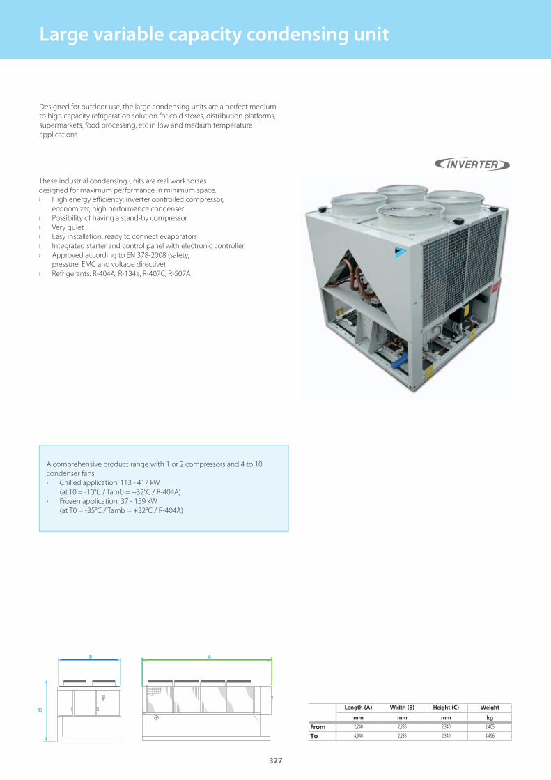
Large variable capacity condensing unit
Length (A) Width (B) Height (C) Weight
mm mm mm kg
FromTo
A comprehensive product range with 1 or 2 compressors and 4 to 10
condenser fans
› Chilled application: 113 - 417 kW
(at T0 = -10°C / Tamb = +32°C / R-404A)
› Frozen application: 37 - 159 kW
(at T0 = -35°C / Tamb = +32°C / R-404A)
Designed for outdoor use, the large condensing units are a perfect medium
to high capacity refrigeration solution for cold stores, distribution platforms,
supermarkets, food processing, etc in low and medium temperature
applications
These industrial condensing units are real workhorses
designed for maximum performance in minimum space.
› High energy efficiency: inverter controlled compressor,
economizer, high performance condenser
› Possibility of having a stand-by compressor
› Very quiet
› Easy installation, ready to connect evaporators
› Integrated starter and control panel with electronic controller
› Approved according to EN 378-2008 (safety,
pressure, EMC and voltage directive)
› Refrigerants: R-404A, R-134a, R-407C, R-507A
2,240 2,235 2,340 2,405
4,940 2,235 2,340 4,496
327
GC_pre2_lowres.pdf 327 30/11/2011 12:32:05

GC_pre2_lowres.pdf 328 30/11/2011 12:32:05
��
CONTROL SYSTEMS, OPTIONS & ACCESSORIES
CONTROL SYSTEMS
Remote monitoring and maintenance 330
ACNSS (Air Conditioning Network Service System) 330
Individual control systems 333
Wired remote control 333Infrared remote control 333Simplifi ed built-in remote control for hotel applications 333Simplifi ed remote control 333Online controller 334Universal control - RTD-10, RTD-HO 336
Centralised control systems 337
Centralised remote control 337Unifi ed on/off control 337Schedule timer 337
Daikin control systems 338
338
339
340
Stadard protocol interfaces 341
Modbus interface - RTD-net 341KNX Interface 341 342 342
OPTIONS & ACCESSORIES 343
Wireless room temperature sensor 343Wired room temperature sensor 343Other intergration devices 344
OPTION LISTS
Split 346Sky Air 348VRV outdoor 352VRV indoor 354Ventilation 356Chillers 358Fan coil units 362
NEW
NEW
NEW
NEW
NEW
NEW
NEW
GC_pre2_lowres.pdf 329 30/11/2011 12:32:06
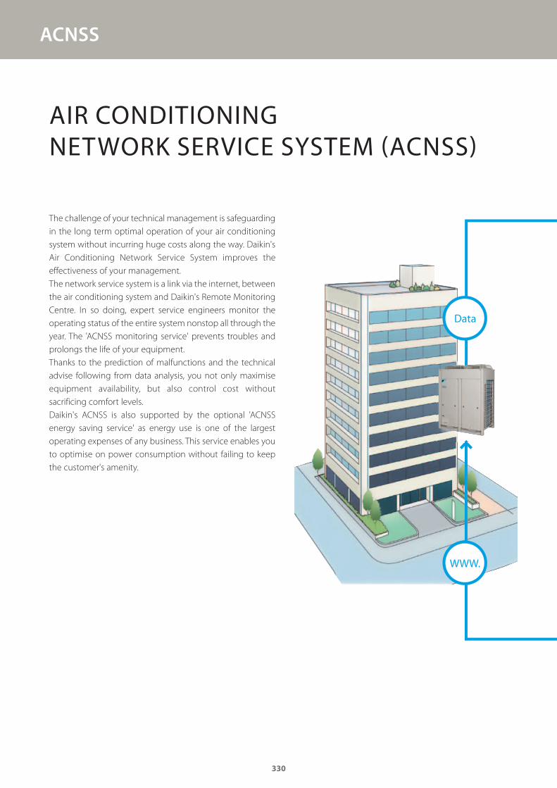
ACNSS
AIR CONDITIONING NETWORK SERVICE SYSTEM (ACNSS)
The challenge of your technical management is safeguarding
in the long term optimal operation of your air conditioning
system without incurring huge costs along the way. Daikin's
Air Conditioning Network Service System improves the
effectiveness of your management.
The network service system is a link via the internet, between
the air conditioning system and Daikin's Remote Monitoring
Centre. In so doing, expert service engineers monitor the
operating status of the entire system nonstop all through the
year. The 'ACNSS monitoring service' prevents troubles and
prolongs the life of your equipment.
Thanks to the prediction of malfunctions and the technical
advise following from data analysis, you not only maximise
equipment availability, but also control cost without
sacrificing comfort levels.
Daikin's ACNSS is also supported by the optional 'ACNSS
energy saving service' as energy use is one of the largest
operating expenses of any business. This service enables you
to optimise on power consumption without failing to keep
the customer's amenity.
Data
WWW.
330
GC_pre2_lowres.pdf 330 30/11/2011 12:32:06
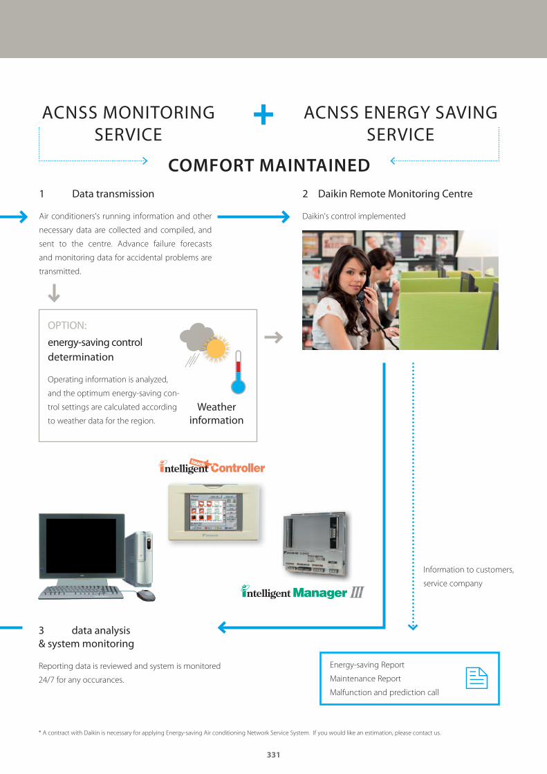
1 Data transmission
Air conditioners's running information and other
necessary data are collected and compiled, and
sent to the centre. Advance failure forecasts
and monitoring data for accidental problems are
transmitted.
3 data analysis & system monitoring
Reporting data is reviewed and system is monitored
24/7 for any occurances.
Energy-saving Report
Maintenance Report
Malfunction and prediction call
Weather information
2 Daikin Remote Monitoring Centre
Daikin's control implemented
Information to customers,
service company
* A contract with Daikin is necessary for applying Energy-saving Air conditioning Network Service System. If you would like an estimation, please contact us.
energy-saving control determination
Operating information is analyzed,
and the optimum energy-saving con-
trol settings are calculated according
to weather data for the region.
ACNSS ENERGY SAVING SERVICE
ACNSS MONITORINGSERVICE
COMFORT MAINTAINED
OPTION:
331
GC_pre2_lowres.pdf 331 30/11/2011 12:32:06
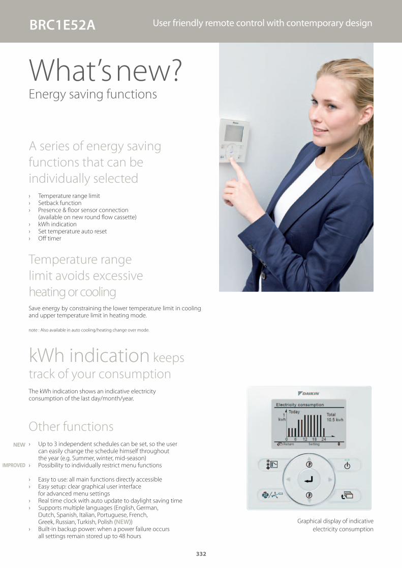
Graphical display of indicative
electricity consumption
BRC1E52A User friendly remote control with contemporary design
A series of energy saving
functions that can be
individually selected
› Temperature range limit › Setback function › Presence & fl oor sensor connection
(available on new round fl ow cassette) › kWh indication › Set temperature auto reset › Off timer
Temperature range
limit avoids excessive
heating or coolingSave energy by constraining the lower temperature limit in cooling and upper temperature limit in heating mode.
note : Also available in auto cooling/heating change over mode.
kWh indication keeps
track of your consumption
The kWh indication shows an indicative electricity consumption of the last day/month/year.
Other functions
› Up to 3 independent schedules can be set, so the user can easily change the schedule himself throughout the year (e.g. Summer, winter, mid-season)
› Possibility to individually restrict menu functions
› Easy to use: all main functions directly accessible › Easy setup: clear graphical user interface
for advanced menu settings › Real time clock with auto update to daylight saving time › Supports multiple languages (English, German,
Dutch, Spanish, Italian, Portuguese, French, Greek, Russian, Turkish, Polish (NEW))
› Built-in backup power: when a power failure occurs all settings remain stored up to 48 hours
What’s new? Energy saving functions
NEW
IMPROVED
332
GC_pre2_lowres.pdf 332 30/11/2011 12:32:06
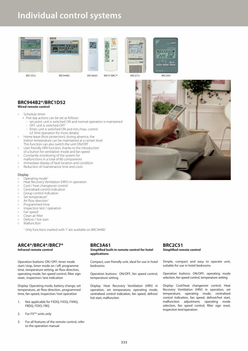
Individual control systems
BRC944B2*/BRC1D52Wired remote control
› Schedule timer:• Five day actions can be set as follows:
- set point: unit is switched ON and normal operation is maintained - OFF: unit is switched OFF1
- limits: unit is switched ON and min./max. control (cf. limit operation for more details)
› Home leave (frost protection): during absence, the indoor temperature can be maintained at a certain level. This function can also switch the unit ON/OFF
› User friendly HRV function, thanks to the introduction of a button for ventilation mode and fan speed
› Constantly monitoring of the system for malfunctions in a total of 80 components
› Immediate display of fault location and condition › Reduction of maintenance time and costs
Display › Operating mode1
› Heat Recovery Ventilation (HRV) in operation › Cool / heat changeover control › Centralised control indication › Group control indication › Set temperature1
› Air flow direction1
› Programmed time › Inspection test / operation › Fan speed1
› Clean air filter › Defrost / hot start › Malfunction
ARC4*/BRC4*/BRC7*Infrared remote control
Operation buttons: ON / OFF, timer mode start / stop, timer mode on / off, programme time, temperature setting, air flow direction, operating mode, fan speed control, filter sign reset , inspection / test indication Display: Operating mode, battery change, set temperature, air flow direction , programmed time, fan speed, inspection / test operation
1. Not applicable for FXDQ, FXSQ, FXNQ, FBDQ, FDXS, FBQ
2. For FX** units only
3. For all features of the remote control, refer to the operation manual
BRC3A61Simplified built-in remote control for hotel
applications
Compact, user friendly unit, ideal for use in hotel bedrooms
Operation buttons: ON/OFF, fan speed control, temperature setting
Display: Heat Recovery Ventilation (HRV) in operation, set temperature, operating mode, centralised control indication, fan speed, defrost/hot start, malfunction
BRC2C51Simplified remote control
Simple, compact and easy to operate unit, suitable for use in hotel bedrooms
Operation buttons: ON/OFF, operating mode selection, fan speed control, temperature setting
Display: Cool/heat changeover control, Heat Recovery Ventilation (HRV) in operation, set temperature, operating mode, centralised control indication, fan speed, defrost/hot start, malfunction adjustment, operating mode selection, fan speed control, filter sign reset, inspection test/operation
1 Only functions marked with ‘1’ are available on BRC944B2
333
BRC3A61BRC2C51BRC4*/BRC7*ARC466A1BRC1D52 BRC944B2
GC_pre2_lowres.pdf 333 30/11/2011 12:32:07

334
no matter where you are
Always in control, Daikin provides a new control solution to monitor and control
the main functions of the residential indoor units. The system is
working in an end-user friendly way and can be used from any
location via your smartphone, laptop, PC, tablet, app
or wired remote controller.
Residential use:Optimal home comfort / holiday home surveillance
› Create a comfortable home climate
at any time and at any place
› Remote detection of failures
Light commercial use:Flexible offi ce solution
› Dynamic group control in open space
› Fault manager / event logger
› Easily create a yearly schedule (iPlanner)
› Back-up confi guration of air conditioning
Residential* Light commercial ** Extended light commercial **
Possibility to control indoor unit via internet � � �
Possibility to control multiple indoor units via internet (up to 9 KKRP01s) � � �
Possibility to control multiple indoor units via internet (over 9 KKRP01s) � �
Filtering data OK / ERR � �
Advanced fi ltering (OK / ANY ERR / COMM ERR / AC / ERR) �
Sorting by all columns from data-grid � �
History of alerts �
History of temperatures �
History of commands �
Graphic single controller with weather forecast � � �
Text group controller � � �
Weekly planner �
I-planner (yearly schedule) � �
Receive via e-mail an alert report � � �
Autonomous periodical connectivity check �
Exceeded room temperature limits e-mail report �
Available software packages
* standard programmed on KKRP01A** Additional software to be purchased online
PC
Smartphone
Wired controller
Individual control systems Online controller
334
1
2
3
GC_pre2_lowres.pdf 334 30/11/2011 12:32:07
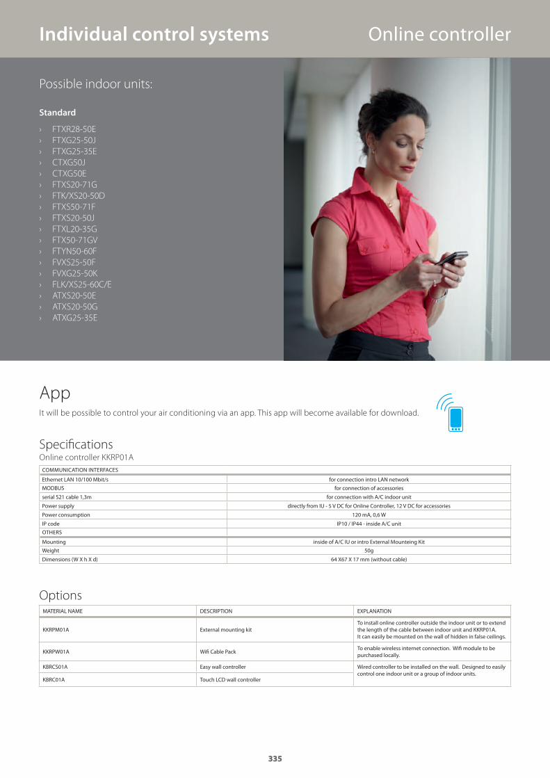
Individual control systems
335
Possible indoor units:
Standard
› FTXR28-50E
› FTXG25-50J
› FTXG25-35E
› CTXG50J
› CTXG50E
› FTXS20-71G
› FTK/XS20-50D
› FTXS50-71F
› FTXS20-50J
› FTXL20-35G
› FTX50-71GV
› FTYN50-60F
› FVXS25-50F
› FVXG25-50K
› FLK/XS25-60C/E
› ATXS20-50E
› ATXS20-50G
› ATXG25-35E
Specifications
COMMUNICATION INTERFACES
Ethernet LAN 10/100 Mbit/s for connection intro LAN network
MODBUS for connection of accessories
serial S21 cable 1,3m for connection with A/C indoor unit
Power supply directly from IU - 5 V DC for Online Controller, 12 V DC for accessories
Power consumption 120 mA, 0,6 W
IP code IP10 / IP44 - inside A/C unit
OTHERS
Mounting inside of A/C IU or intro External Mounteing Kit
Weight 50g
Dimensions (W X h X d) 64 X67 X 17 mm (without cable)
Options
Online controller KKRP01A
MATERIAL NAME DESCRIPTION EXPLANATION
KKRPM01A External mounting kitTo install online controller outside the indoor unit or to extend the length of the cable between indoor unit and KKRP01A. It can easily be mounted on the wall of hidden in false ceilings.
KKRPW01A Wifi Cable PackTo enable wireless internet connection. Wifi module to be purchased locally.
KBRCS01A Easy wall controller Wired controller to be installed on the wall. Designed to easily control one indoor unit or a group of indoor units.
KBRC01A Touch LCD wall controller
Online controller
AppIt will be possible to control your air conditioning via an app. This app will become available for download.
335
GC_pre2_lowres.pdf 335 30/11/2011 12:32:07
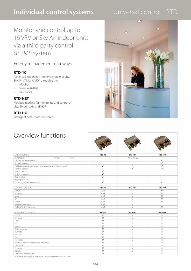
Monitor and control up to
16 VRV or Sky Air indoor units
via a third party control
or BMS system
RTD-10Advanced integration into BMS system of VRV,
Sky Air, VAM and VKM through either:
› Modbus
› Voltage (0-10V)
› Resistance
RTD-NETModbus interface for monitoring and control of
VRV, Sky Air, VAM and VKM
RTD-HOIntelligent hotel room controller
Energy management gateways
MAIN FUNCTIONS RTD-10 RTD-NET RTD-HO
Dimensions H x W x D mm 100 x100 x 22
Key card + window contact �Set back function �Prohibit or restrict remote control functions (setpoint limitation, ...) � � �Modbus (RS485) � � �0 - 10 V control �Resistance control �IT application �Heating interlock �Output signal (on/defrost, error) � �
CONTROL FUNCTIONS RTD-10 RTD-NET RTD-HO
On/Off M,V,R M M*
Set point M,V,R M M*
Mode M,V,R M M*
fan M,V,R M M*
Louver M,V,R M M*
HRV Damper control M,V,R M
Prohibit/Restrict functions M,V,R M M*
MONITORING FUNCTIONS RTD-10 RTD-NET RTD-HO
On/Off M M M
Set point M M M
Mode M M M
fan M M M
Louver M M M
RC temperature M M M
RC mode M M M
nbr units M M M
Fault M M M
Fault code M M M
Return air temperature (Average /Min/Max) M M M
Filter alarm M M M
Termo on M M M
Defrost M M M
Coil In/Out temperature M M M
Overview functions
Individual control systems
M: Modbus, V: Voltage, R: Resistance, *: only when the room is occupied
Universal control - RTD
336
GC_pre2_lowres.pdf 336 30/11/2011 12:32:07
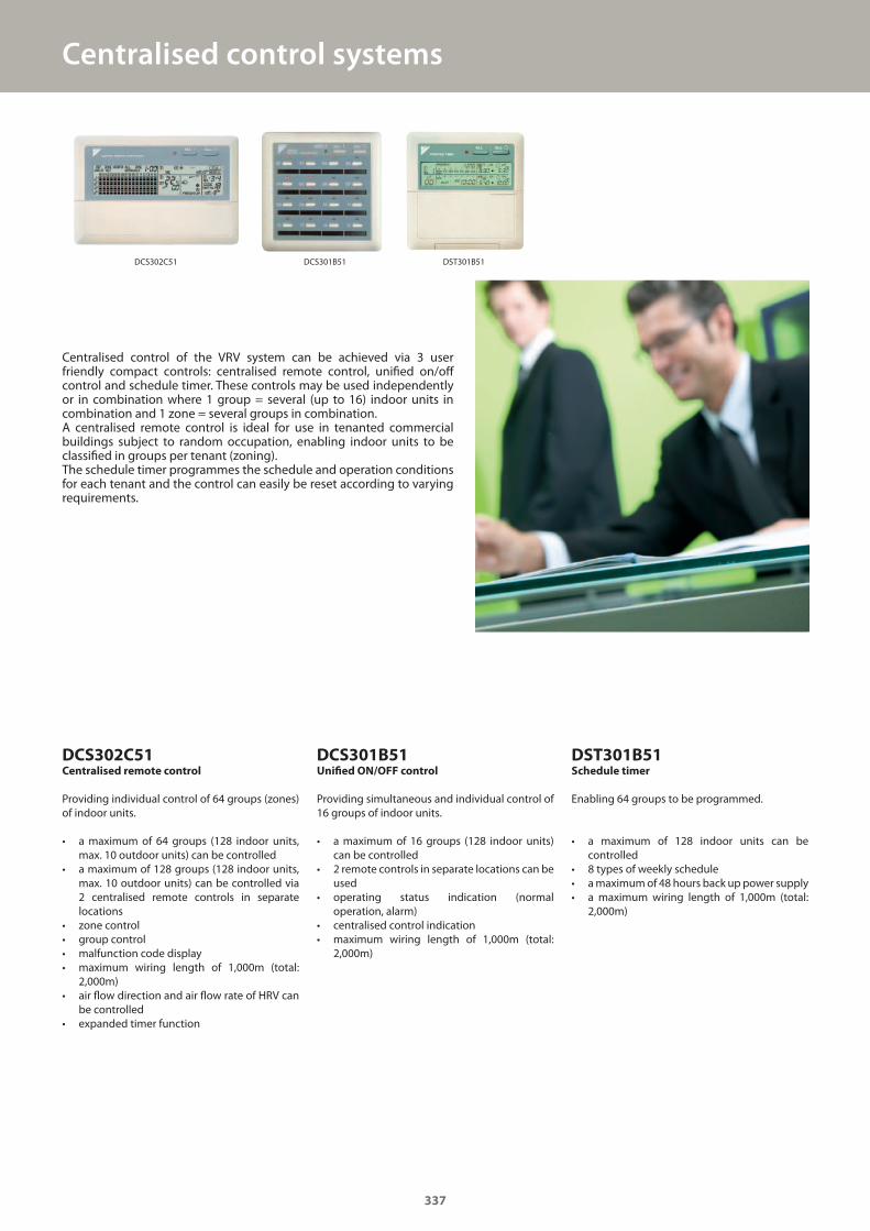
Centralised control of the VRV system can be achieved via 3 user friendly compact controls: centralised remote control, unified on/off control and schedule timer. These controls may be used independently or in combination where 1 group = several (up to 16) indoor units in combination and 1 zone = several groups in combination.A centralised remote control is ideal for use in tenanted commercial buildings subject to random occupation, enabling indoor units to be classified in groups per tenant (zoning). The schedule timer programmes the schedule and operation conditions for each tenant and the control can easily be reset according to varying requirements.
DCS302C51Centralised remote control
Providing individual control of 64 groups (zones) of indoor units.
• a maximum of 64 groups (128 indoor units, max. 10 outdoor units) can be controlled
• a maximum of 128 groups (128 indoor units, max. 10 outdoor units) can be controlled via 2 centralised remote controls in separate locations
• zone control• group control• malfunction code display• maximum wiring length of 1,000m (total:
2,000m)• air flow direction and air flow rate of HRV can
be controlled• expanded timer function
DCS301B51Unified ON/OFF control
Providing simultaneous and individual control of 16 groups of indoor units.
• a maximum of 16 groups (128 indoor units) can be controlled
• 2 remote controls in separate locations can be used
• operating status indication (normal operation, alarm)
• centralised control indication• maximum wiring length of 1,000m (total:
2,000m)
DST301B51Schedule timer
Enabling 64 groups to be programmed.
• a maximum of 128 indoor units can be controlled
• 8 types of weekly schedule • a maximum of 48 hours back up power supply• a maximum wiring length of 1,000m (total:
2,000m)
Centralised control systems
337
DST301B51DCS301B51DCS302C51
GC_pre2_lowres.pdf 337 30/11/2011 12:32:07
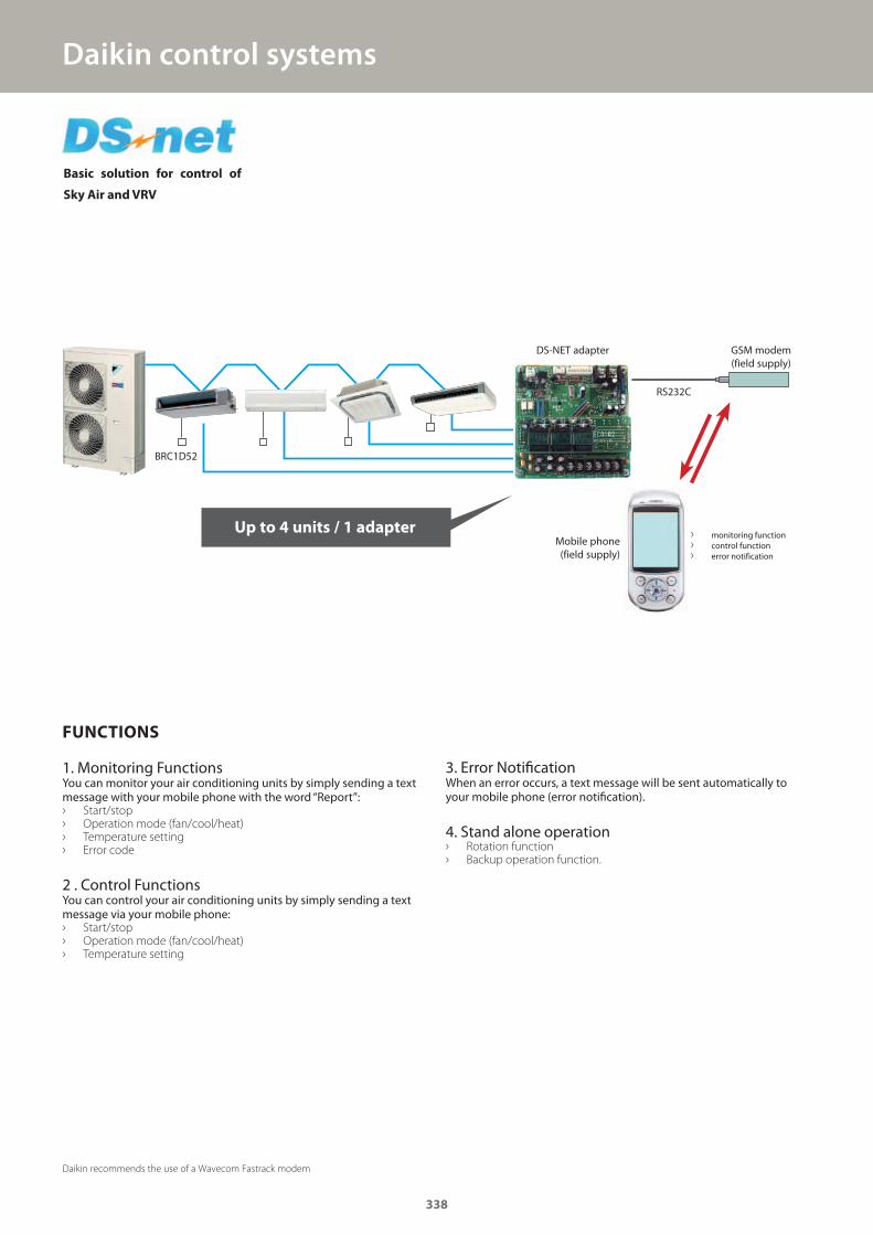
Daikin control systems
FUNCTIONS
1. Monitoring FunctionsYou can monitor your air conditioning units by simply sending a text message with your mobile phone with the word “Report”: › Start/stop › Operation mode (fan/cool/heat) › Temperature setting › Error code
2 . Control FunctionsYou can control your air conditioning units by simply sending a text message via your mobile phone: › Start/stop › Operation mode (fan/cool/heat) › Temperature setting
3. Error NotificationWhen an error occurs, a text message will be sent automatically to your mobile phone (error notification).
4. Stand alone operation › Rotation function › Backup operation function.
Basic solution for control of
Sky Air and VRV
› monitoring function › control function › error notification
Mobile phone(field supply)
Up to 4 units / 1 adapter
GSM modem(field supply)
RS232C
DS-NET adapter
Daikin recommends the use of a Wavecom Fastrack modem
BRC1D52
338
GC_pre2_lowres.pdf 338 30/11/2011 12:32:08
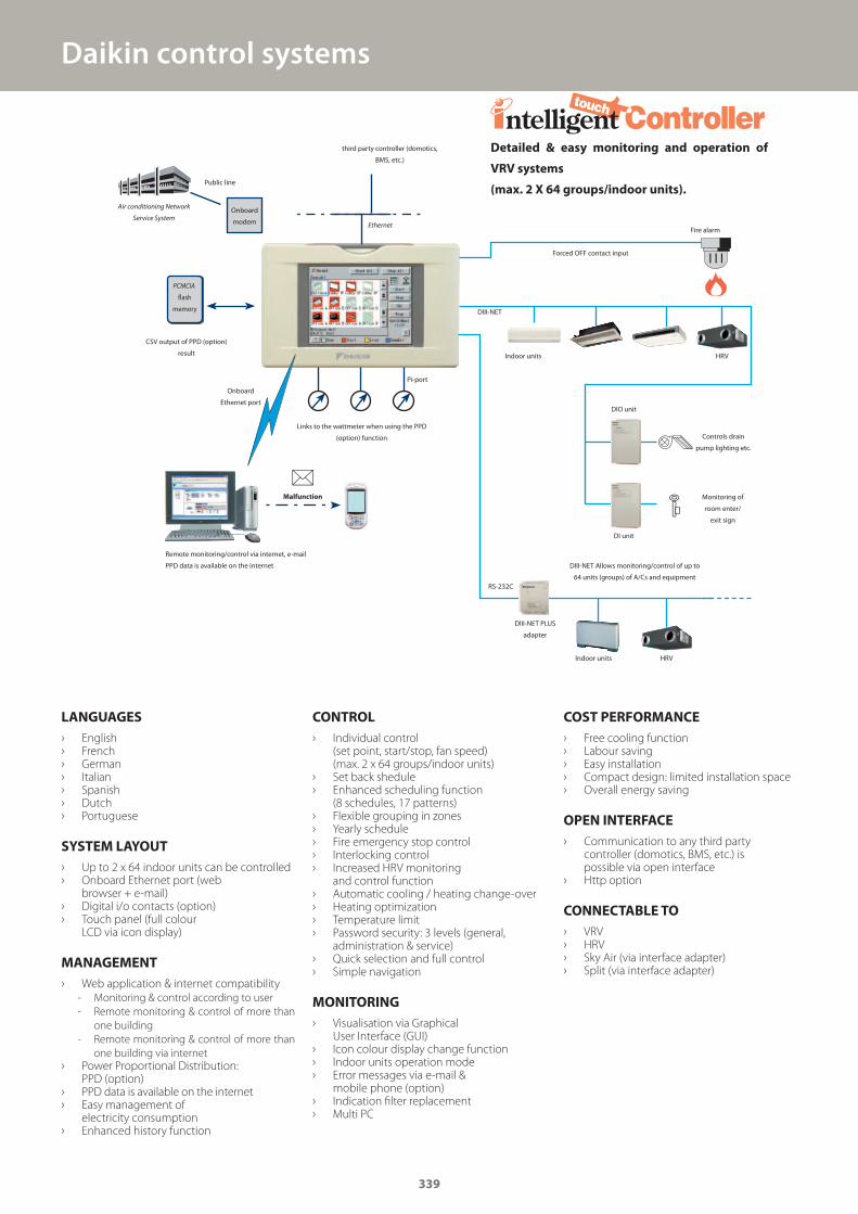
Daikin control systems
LANGUAGES
› English › French › German › Italian › Spanish › Dutch › Portuguese
SYSTEM LAYOUT
› Up to 2 x 64 indoor units can be controlled › Onboard Ethernet port (web
browser + e-mail) › Digital i/o contacts (option) › Touch panel (full colour
LCD via icon display)
MANAGEMENT
› Web application & internet compatibility
- Monitoring & control according to user
- Remote monitoring & control of more than
one building
- Remote monitoring & control of more than
one building via internet
› Power Proportional Distribution: PPD (option)
› PPD data is available on the internet › Easy management of
electricity consumption › Enhanced history function
CONTROL
› Individual control (set point, start/stop, fan speed) (max. 2 x 64 groups/indoor units)
› Set back shedule › Enhanced scheduling function
(8 schedules, 17 patterns) › Flexible grouping in zones › Yearly schedule › Fire emergency stop control › Interlocking control › Increased HRV monitoring
and control function › Automatic cooling / heating change-over › Heating optimization › Temperature limit › Password security: 3 levels (general,
administration & service) › Quick selection and full control › Simple navigation
MONITORING
› Visualisation via Graphical User Interface (GUI)
› Icon colour display change function › Indoor units operation mode › Error messages via e-mail &
mobile phone (option) › Indication fi lter replacement › Multi PC
COST PERFORMANCE
› Free cooling function › Labour saving › Easy installation › Compact design: limited installation space › Overall energy saving
OPEN INTERFACE
› Communication to any third party controller (domotics, BMS, etc.) is possible via open interface
› Http option
CONNECTABLE TO
› VRV › HRV › Sky Air (via interface adapter) › Split (via interface adapter)
Detailed & easy monitoring and operation of
VRV systems
(max. 2 X 64 groups/indoor units).
Malfunction
Remote monitoring/control via internet, e-mail
PPD data is available on the internet
Onboard
Ethernet port
Links to the wattmeter when using the PPD
(option) function
Pi-port
Public line
Air conditioning Network
Service System
CSV output of PPD (option)
result
third party controller (domotics,
BMS, etc.)
Ethernet Fire alarm
DIII-NET
DIO unit
DI unit
Controls drain
pump lighting etc.
Monitoring of
room enter/
exit sign
DIII-NET Allows monitoring/control of up to
64 units (groups) of A/Cs and equipment
DIII-NET PLUS
adapter
Forced OFF contact input
HRV
HRV
Indoor units
Indoor units
RS-232C
Onboard
modem
PCMCIA
fl ash
memory
339
GC_pre2_lowres.pdf 339 30/11/2011 12:32:08
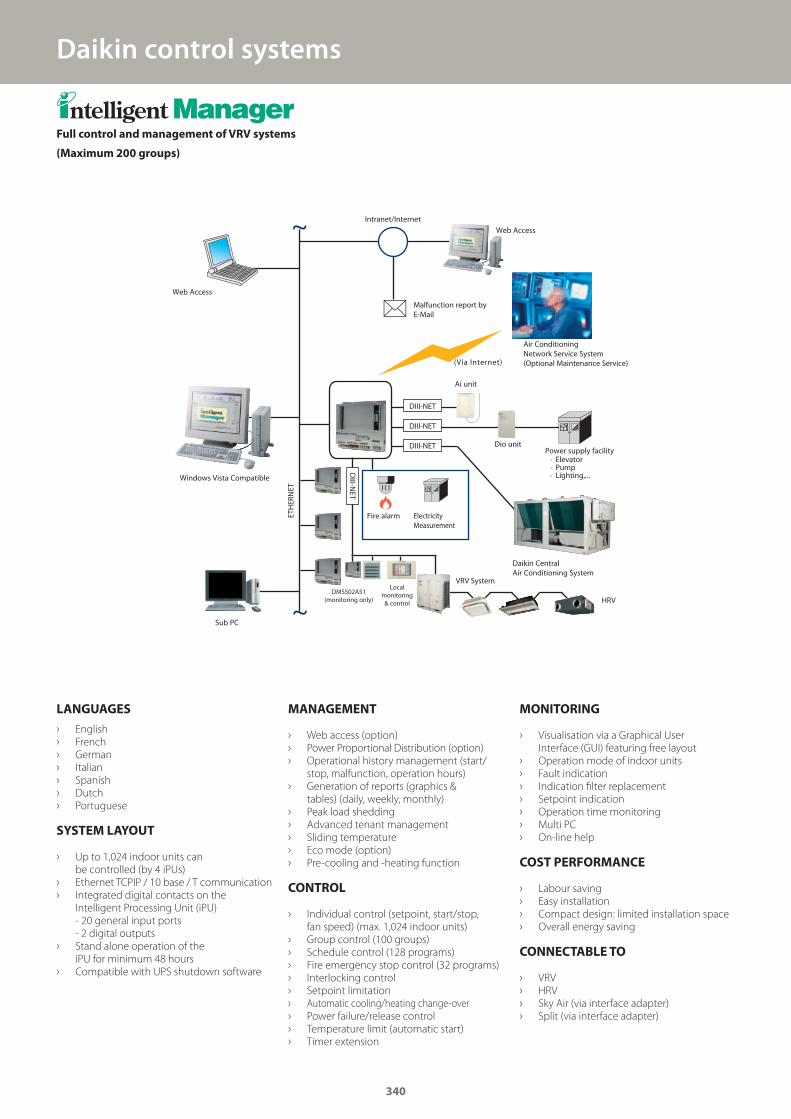
Daikin control systems
LANGUAGES
› English
› French
› German
› Italian
› Spanish
› Dutch
› Portuguese
SYSTEM LAYOUT
› Up to 1,024 indoor units can
be controlled (by 4 iPUs)
› Ethernet TCPIP / 10 base / T communication
› Integrated digital contacts on the
Intelligent Processing Unit (iPU)
- 20 general input ports
- 2 digital outputs
› Stand alone operation of the
iPU for minimum 48 hours
› Compatible with UPS shutdown software
MANAGEMENT
› Web access (option)
› Power Proportional Distribution (option)
› Operational history management (start/
stop, malfunction, operation hours)
› Generation of reports (graphics &
tables) (daily, weekly, monthly)
› Peak load shedding
› Advanced tenant management
› Sliding temperature
› Eco mode (option)
› Pre-cooling and -heating function
CONTROL
› Individual control (setpoint, start/stop,
fan speed) (max. 1,024 indoor units)
› Group control (100 groups)
› Schedule control (128 programs)
› Fire emergency stop control (32 programs)
› Interlocking control
› Setpoint limitation
› Automatic cooling/heating change-over
› Power failure/release control
› Temperature limit (automatic start)
› Timer extension
MONITORING
› Visualisation via a Graphical User
Interface (GUI) featuring free layout
› Operation mode of indoor units
› Fault indication
› Indication filter replacement
› Setpoint indication
› Operation time monitoring
› Multi PC
› On-line help
COST PERFORMANCE
› Labour saving
› Easy installation
› Compact design: limited installation space
› Overall energy saving
CONNECTABLE TO
› VRV
› HRV
› Sky Air (via interface adapter)
› Split (via interface adapter)
Full control and management of VRV systems
(Maximum 200 groups)
DIII-NET
DIII-NET
DIII-NET
Web Access
Sub PC
ETH
ERN
ET
Intranet/InternetWeb Access
Malfunction report by E-Mail
Dio unit
· Elevator· Pump· Lighting,...
Power supply facility
Ai unit
Daikin Central Air Conditioning System
VRV SystemLocal
monitoring & control
Air Conditioning Network Service System (Optional Maintenance Service)
HRV
Electricity Measurement
Fire alarm
(Via Internet)
DAM602B51/52
DIII-N
ET
DMS502A51(monitoring only)
Windows Vista Compatible
340
~
~
GC_pre2_lowres.pdf 340 30/11/2011 12:32:08
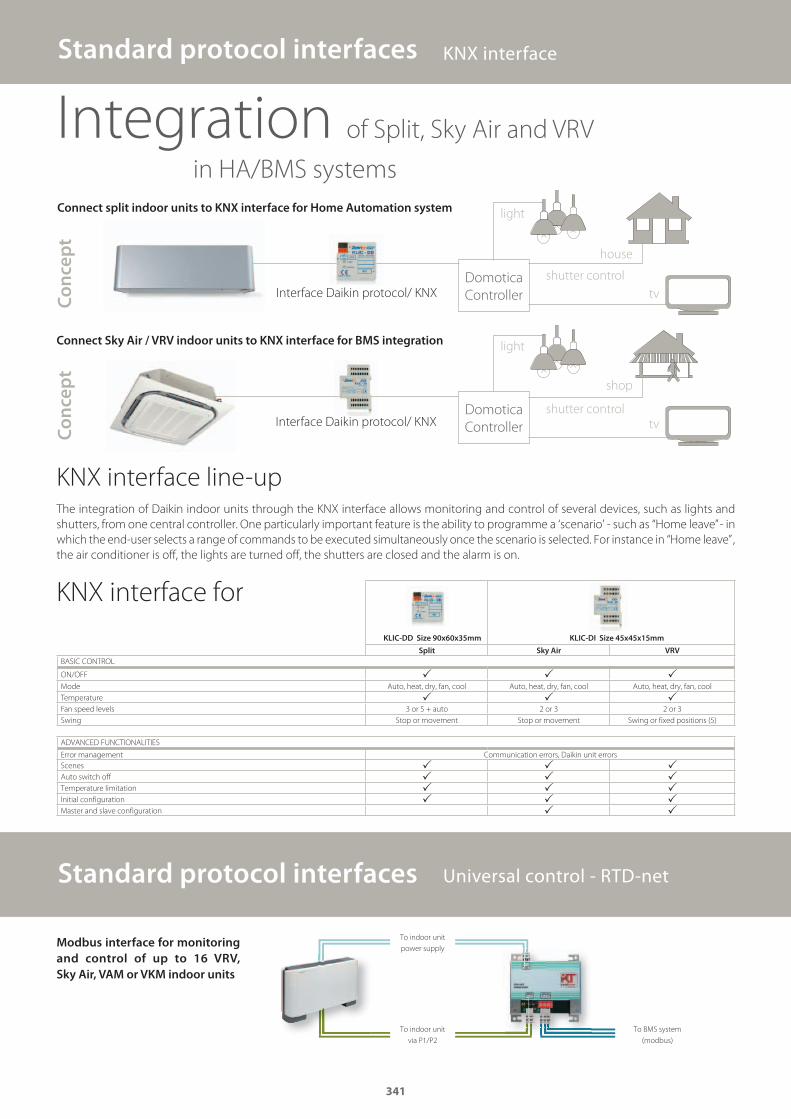
KLIC-DD Size 90x60x35mm KLIC-DI Size 45x45x15mm
Split Sky Air VRV
BASIC CONTROL
ON/OFF � � �Mode Auto, heat, dry, fan, cool Auto, heat, dry, fan, cool Auto, heat, dry, fan, cool
Temperature � � �Fan speed levels 3 or 5 + auto 2 or 3 2 or 3
Swing Stop or movement Stop or movement Swing or fixed positions (5)
ADVANCED FUNCTIONALITIES
Error management Communication errors, Daikin unit errors
Scenes � � �Auto switch off � � �Temperature limitation � � �Initial configuration � � �Master and slave configuration � �
Modbus interface for monitoring
and control of up to 16 VRV,
Sky Air, VAM or VKM indoor units
Standard protocol interfaces Universal control - RTD-net
Standard protocol interfaces KNX interface
Integration of Split, Sky Air and VRV
in HA/BMS systems
Domotica
Controller
shutter control
house
Co
nce
pt
Co
nce
pt
Domotica
Controller
Connect split indoor units to KNX interface for Home Automation system
Connect Sky Air / VRV indoor units to KNX interface for BMS integration
KNX interface line-upThe integration of Daikin indoor units through the KNX interface allows monitoring and control of several devices, such as lights and
shutters, from one central controller. One particularly important feature is the ability to programme a ‘scenario’ - such as “Home leave” - in
which the end-user selects a range of commands to be executed simultaneously once the scenario is selected. For instance in “Home leave” ,
the air conditioner is off, the lights are turned off, the shutters are closed and the alarm is on.
light
light
shutter control
shop
KNX interface for
To indoor unit
power supply
To indoor unit
via P1/P2
To BMS system
(modbus)
341
tv
tv
Interface Daikin protocol/ KNX
Interface Daikin protocol/ KNX
GC_pre2_lowres.pdf 341 30/11/2011 12:32:08
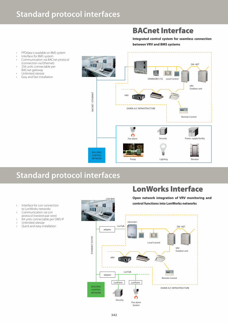
Standard protocol interfaces
Open network integration of VRV monitoring and
control functions into LonWorks networks › Interface for Lon connection
to LonWorks networks › Communication via Lon
protocol (twisted pair wire) › 64 units connectable per DMS-IF › Unlimited sitesize › Quick and easy installation
LON BMS
Fire alarm System
Security
BUILDING CONTROL NETWORK
adapter
LonTalk
LonTalk
LonPoint LonPoint
ETH
ERN
ET (T
CP/
IP)
adapter
DMS504B51
Local Control
DIII- NET
VRV Outdoor unit
HRV
Remote Control
DAIKIN A/C INFRASTRUCTURE
Standard protocol interfaces
› PPDdata is available on BMS system › Interface for BMS system › Communication via BACnet protocol
(connection via Ethernet) › 256 units connectable per
BACnet gateway › Unlimited sitesize › Easy and fast installation
BACN
ET /
ETH
ERN
ET
Fire alarm Security
Local Control
DIII- NET
VRV Outdoor unit
Remote Control
DAIKIN A/C INFRASTRUCTURE
Power supply facility
Pump Lighting Elevator
HRV
DAM602B51/52
Integrated control system for seamless connection
between VRV and BMS systems
BUILDING CONTROL NETWORK
342
BACnet Interface
LonWorks Interface
GC_pre2_lowres.pdf 342 30/11/2011 12:32:09
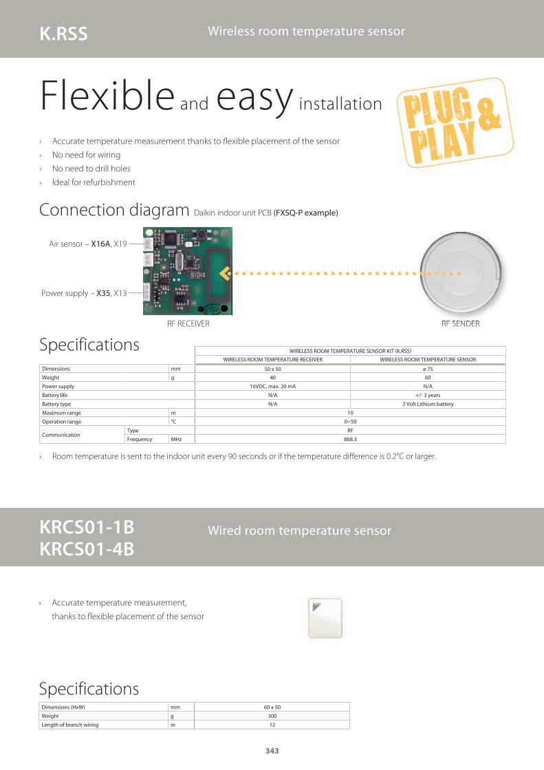
Wireless room temperature sensor
Flexible and easy installation
› Accurate temperature measurement thanks to fl exible placement of the sensor
› No need for wiring
› No need to drill holes
› Ideal for refurbishment
Connection diagram Daikin indoor unit PCB (FXSQ-P example)
Power supply – X35, X13
Air sensor – X16A, X19
RF SENDERRF RECEIVER
› Room temperature is sent to the indoor unit every 90 seconds or if the temperature diff erence is 0.2°C or larger.
WIRELESS ROOM TEMPERATURE SENSOR KIT (K.RSS)
WIRELESS ROOM TEMPERATURE RECEIVER WIRELESS ROOM TEMPERATURE SENSOR
Dimensions mm 50 x 50 ø 75
Weight g 40 60
Power supply 16VDC, max. 20 mA N/A
Battery life N/A +/- 3 years
Battery type N/A 3 Volt Lithium battery
Maximum range m 10
Operation range °C 0~50
CommunicationType RF
Frequency MHz 868.3
Specifications
KRCS01-1BKRCS01-4B
Wired room temperature sensor
› Accurate temperature measurement,
thanks to fl exible placement of the sensor
Dimensions (HxW) mm 60 x 50
Weight g 300
Length of branch wiring m 12
Specifications
343
K.RSS
GC_pre2_lowres.pdf 343 30/11/2011 12:32:09

Adapter PCB’s – Simple solutions for unique requirementsOther integration devices
(E)KRP1B*
adapter for wiring
• Facilitates integration of auxiliary heating apparatus, humidifiers, fans, damper• Powered by and installed at the indoor unit
KRP2A*/KRP4A*
Wiring adapter for electrical appendices
• Remotely start and stop up to 16 indoor units (1 group) (KRP4A* via P1 P2)• Remotely start and stop up to 128 indoor units (64 groups) (KRP2A* via F1 F2) • Alarm indication/ fire shut down• Remote temperature setpoint adjustment
DTA104A*
Outdoor Unit External Control Adapter
• Individual or simultaneous control of VRV system operating mode• Demand control of individual or multiple systems• Low noise option for individual or multiple systems
Daikin’s adapter PCB’s provide simple solutions for unique requirements. They are a low cost option to satisfy simple control requirements
and can be used on single or multiple units.
Concept and benefits › Low cost option to satisfy simple control requirements
› Deployed on single or multiple units
GC_pre2_lowres.pdf 344 30/11/2011 12:32:09
���
OPTION LISTS
Split 346Sky Air 348VRV outdoor 352VRV indoor 354Ventilation 356Chillers 358Fan coil units 362
GC_pre2_lowres.pdf 345 30/11/2011 12:32:10
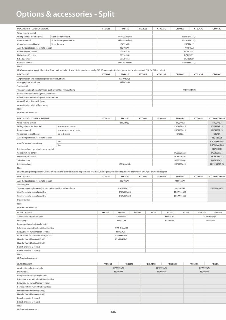
INDOOR UNITS FTXR28E FTXR42E FTXR50E CTXU25G CTXU35G CTXU42G CTXU50G
Air purification and deodorising filter set without frame KAF974B42S
Air supply filter with frame KAF963A43
Suction grille
Titanium apatite photocatalytic air-purification filter without frame KAF970A47 (1)
Photocatalytic deodorising filter, with frame
Photocatalytic deodorising filter, without frame
Air purification filter, with frame
Air purification filter, without frame
Notes
(1) Standard accessory
INDOOR UNITS - CONTROL SYSTEMS FTX20JV FTX25JV FTX35JV FTX50GV FTX60GV FTX71GV *FTXS20K/CTXS15K
Wired remote control BRC944B2 BRC944B2 BRC944B2
Wiring adapter for time clock Normal open contact KRP413AA1S KRP413AB1S
Remote control Normal open pulse contact KRP413AA1S KRP413AB1S
Centralised control board Up to 5 rooms KRC72A KRC72A
Anti-theft protection for remote control KKF910A4
Cord for remote control assy3m BRCW901A03
8m BRCW901A08
Interface adapter for wired remote control KRP980B1
Central remote control DCS302CA61 DCS302CA51
Unified on/off control DCS301BA61 DCS301BA51
Schedule timer DST301BA61 DST301BA51
Interface adapter KRP980A1 (3) KRP928BA2S KRP928BB2S (3)
Notes
(1) Wiring adapter supplied by Daikin. Time clock and other devices: to be purchased locally. / (2) Wiring adapter is also required for each indoor unit. / (3) For DIII-net adapter
INDOOR UNITS FTX20JV FTX25JV FTX35JV FTX50GV FTX60GV FTX71GV *FTXS20K/CTXS15K
Anti-theft protection for remote control KKF936A4 KKF917AA4
Suction grille -
Titanium apatite photocatalytic air-purification filter without frame KAF971A42 (1) KAF952B42 KAF970A46 (1)
Cord for remote control assy (3m) BRCW901A03 BRCW901A03
Cord for remote control assy (8m) BRCW901A08 BRCW901A08
Installation leg
Notes
(1) Standard accessory
OUTDOOR UNITS RXR28E RXR42E RXR50E RX20J RX25J RX35J RX50GV RX60GV
Air direction adjustment grille KPW937A4 KPW937B4 KRP945A(A)4
Drain plug (1) KKP937A4 KKP937A4 KKP937A4
Refrigerant branch piping for twin
Extension hose set for humidification (2m) KPMH942A402
Relay joint for humidification (10pcs.) KPMJ942A4
L-shape cuffs for humidification (10pcs) KPMH950A4L
Hose for humidification (10m)(l) KPMH942A42
Hose for humidification (15m)(l)
Branch provider (2 rooms)
Branch provider (3 rooms)
Notes
(1) Standard accessory
OUTDOOR UNITS *RXS20K *RXS25K *RXLG25K *RXLG35K *RXL20J *RXL25J
Air direction adjustment grille KPW937AA4 KPW937AA4 KPW937AA4
Drain plug (1) KKP937A4 KKP937A4 KKP937A4
Refrigerant branch piping for twin
Extension hose set for humidification (2m)
Relay joint for humidification (10pcs.)
L-shape cuffs for humidification (10pcs)
Hose for humidification (10m)(l)
Hose for humidification (15m)(l)
Branch provider (2 rooms)
Branch provider (3 rooms)
Notes
(1) Standard accessory
Options & accessories - Split
INDOOR UNITS - CONTROL SYSTEMS FTXR28E FTXR42E FTXR50E CTXU25G CTXU35G CTXU42G CTXU50G
Wired remote control
Wiring adapter for time clock Normal open contact KRP413AA1S (1) KRP413AA1S (1)
Remote control Normal open pulse contact KRP413AA1S (1) KRP413AA1S (1)
Centralised control board Up to 5 rooms KRC72A (2) KRC72A (2)
Anti-theft protection for remote control KKF936A4 KKF910A4
Central remote control DCS302C51 DCS302C51
Unified on/off control DCS301B51 DCS301B51
Schedule timer DST301B51 DST301B51
Interface adapter KRP928BA2S (3) KRP928BA2S (3)
Notes
(1) Wiring adapter supplied by daikin. Time clock and other devices: to be purchased locally. / (2) Wiring adapter is also required for each indoor unit. / (3) For DIII-net adapter
346
GC_pre2_lowres.pdf 346 30/11/2011 12:32:10
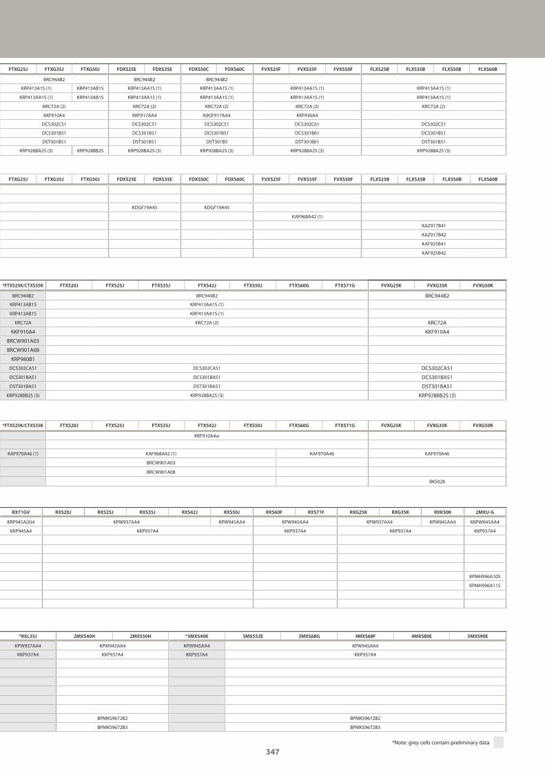
FTXG25J FTXG35J FTXG50J FDXS25E FDXS35E FDXS50C FDXS60C FVXS25F FVXS35F FVXS50F FLXS25B FLXS35B FLXS50B FLXS60B
KDGF19A45 KDGF19A45
KAF968A42 (1)
KAZ917B41
KAZ917B42
KAF925B41
KAF925B42
*FTXS25K/CTXS35K FTXS20J FTXS25J FTXS35J FTXS42J FTXS50J FTXS60G FTXS71G FVXG25K FVXG35K FVXG50K
BRC944B2 BRC944B2 BRC944B2
KRP413AB1S KRP413AA1S (1)
KRP413AB1S KRP413AA1S (1)
KRC72A KRC72A (2) KRC72A
KKF910A4 KKF910A4
BRCW901A03
BRCW901A08
KRP980B1
DCS302CA51 DCS302CA51 DCS302CA51
DCS301BA51 DCS301BA51 DCS301BA51
DST301BA51 DST301BA51 DST301BA51
KRP928BB2S (3) KRP928BA2S (3) KRP928BB2S (3)
*FTXS25K/CTXS35K FTXS20J FTXS25J FTXS35J FTXS42J FTXS50J FTXS60G FTXS71G FVXG25K FVXG35K FVXG50K
KKF910A4w
KAF970A46 (1) KAF968A42 (1) KAF970A46 KAF970A46
BRCW901A03
BRCW901A08
BKS028
RX71GV RXS20J RXS25J RXS35J RXS42J RXS50J RXS60F RXS71F RXG25K RXG35K RXK50K 2MXU-G
KRP945A(A)4 KPW937AA4 KPW945AA4 KPW945AA4 KPW937AA4 KPW945AA4 KKPW945AA4
KKP945A4 KKP937A4 KKP937A4 KKP937A4 KKP937A4
KPMH996A10S
KPMH996A11S
*RXL35J 2MXS40H 2MXS50H *3MXS40K 3MXS52E 3MXS68G 4MXS68F 4MXS80E 5MXS90E
KPW937AA4 KPW945AA4 KPW945AA4 KPW945AA4
KKP937A4 KKP937A4 KKP937A4 KKP937A4
BPMKS9672B2 BPMKS9672B2
BPMKS9672B3 BPMKS9672B3
FTXG25J FTXG35J FTXG50J FDXS25E FDXS35E FDXS50C FDXS60C FVXS25F FVXS35F FVXS50F FLXS25B FLXS35B FLXS50B FLXS60B
BRC944B2 BRC944B2 BRC944B2
KRP413A1S (1) KRP413AB1S KRP413AA1S (1) KRP413AA1S (1) KRP413AA1S (1) KRP413AA1S (1)
KRP413AA1S (1) KRP413AB1S KRP413AA1S (1) KRP413AA1S (1) KRP413AA1S (1) KRP413AA1S (1)
KRC72A (2) KRC72A (2) KRC72A (2) KRC72A (2) KRC72A (2)
KKF910A4 KKF917AA4 K(K)F917AA4 KKF936A4
DCS302C51 DCS302C51 DCS302C51 DCS302C61 DCS302C51
DCS301B51 DCS301B51 DCS301B51 DCS301B61 DCS301B51
DST301B51 DST301B51 DST301B5 DST301B61 DST301B51
KRP928BA2S (3) KRP928BB2S KRP928BA2S (3) KRP928BA2S (3) KRP928BA2S (3) KRP928BA2S (3)
*Note: grey cells contain preliminary data
347
GC_pre2_lowres.pdf 347 30/11/2011 12:32:10
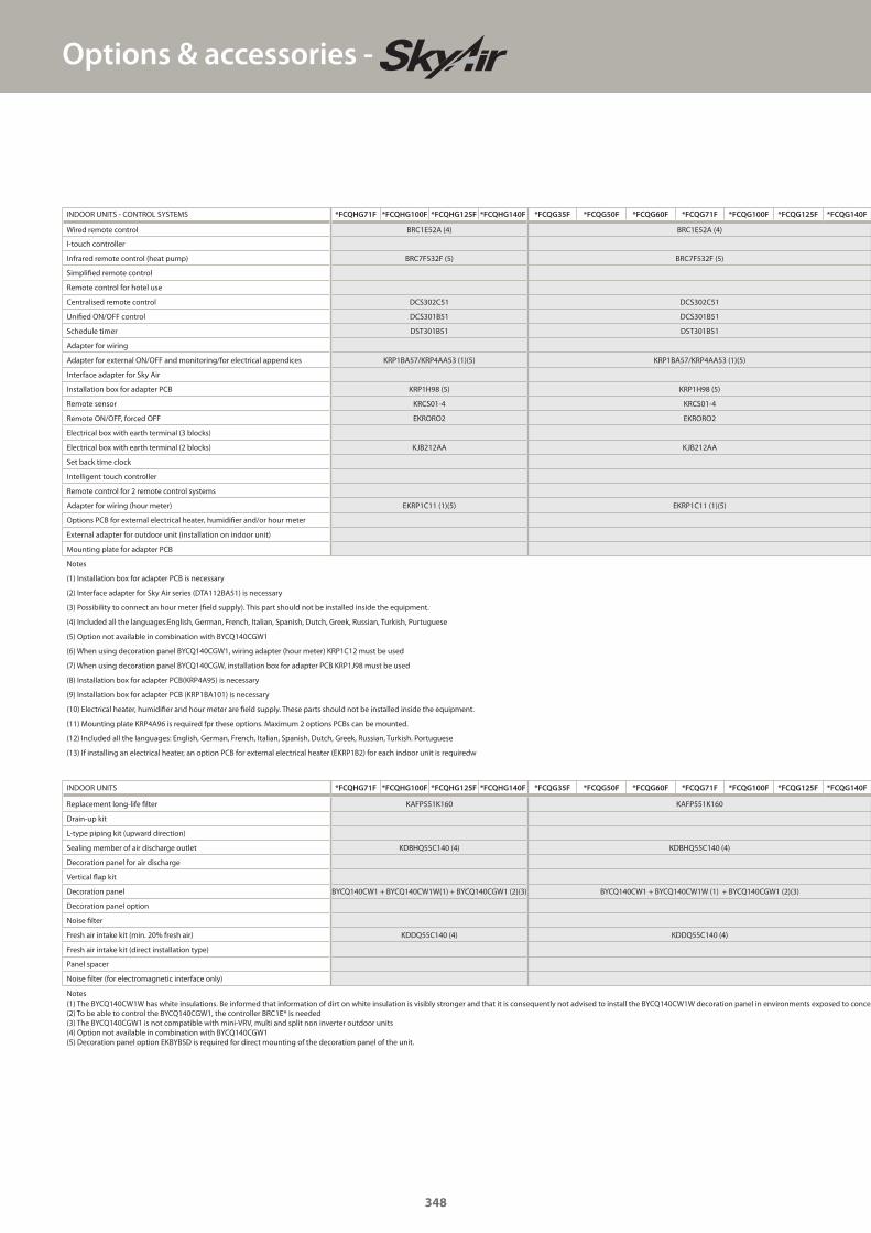
Options & accessories -
INDOOR UNITS *FCQHG71F *FCQHG100F *FCQHG125F *FCQHG140F *FCQG35F *FCQG50F *FCQG60F *FCQG71F *FCQG100F *FCQG125F *FCQG140F
Replacement long-life filter KAFP551K160 KAFP551K160
Drain-up kit
L-type piping kit (upward direction)
Sealing member of air discharge outlet KDBHQ55C140 (4) KDBHQ55C140 (4)
Decoration panel for air discharge
Vertical flap kit
Decoration panel BYCQ140CW1 + BYCQ140CW1W(1) + BYCQ140CGW1 (2)(3) BYCQ140CW1 + BYCQ140CW1W (1) + BYCQ140CGW1 (2)(3)
Decoration panel option
Noise filter
Fresh air intake kit (min. 20% fresh air) KDDQ55C140 (4) KDDQ55C140 (4)
Fresh air intake kit (direct installation type)
Panel spacer
Noise filter (for electromagnetic interface only)
Notes(1) The BYCQ140CW1W has white insulations. Be informed that information of dirt on white insulation is visibly stronger and that it is consequently not advised to install the BYCQ140CW1W decoration panel in environments exposed to concen(2) To be able to control the BYCQ140CGW1, the controller BRC1E* is needed(3) The BYCQ140CGW1 is not compatible with mini-VRV, multi and split non inverter outdoor units(4) Option not available in combination with BYCQ140CGW1(5) Decoration panel option EKBYBSD is required for direct mounting of the decoration panel of the unit.
INDOOR UNITS - CONTROL SYSTEMS *FCQHG71F *FCQHG100F *FCQHG125F *FCQHG140F *FCQG35F *FCQG50F *FCQG60F *FCQG71F *FCQG100F *FCQG125F *FCQG140F
Wired remote control BRC1E52A (4) BRC1E52A (4)
I-touch controller
Infrared remote control (heat pump) BRC7F532F (5) BRC7F532F (5)
Simplified remote control
Remote control for hotel use
Centralised remote control DCS302C51 DCS302C51
Unified ON/OFF control DCS301B51 DCS301B51
Schedule timer DST301B51 DST301B51
Adapter for wiring
Adapter for external ON/OFF and monitoring/for electrical appendices KRP1BA57/KRP4AA53 (1)(5) KRP1BA57/KRP4AA53 (1)(5)
Interface adapter for Sky Air
Installation box for adapter PCB KRP1H98 (5) KRP1H98 (5)
Remote sensor KRCS01-4 KRCS01-4
Remote ON/OFF, forced OFF EKRORO2 EKRORO2
Electrical box with earth terminal (3 blocks)
Electrical box with earth terminal (2 blocks) KJB212AA KJB212AA
Set back time clock
Intelligent touch controller
Remote control for 2 remote control systems
Adapter for wiring (hour meter) EKRP1C11 (1)(5) EKRP1C11 (1)(5)
Options PCB for external electrical heater, humidifier and/or hour meter
External adapter for outdoor unit (installation on indoor unit)
Mounting plate for adapter PCB
Notes
(1) Installation box for adapter PCB is necessary
(2) Interface adapter for Sky Air series (DTA112BA51) is necessary
(3) Possibility to connect an hour meter (field supply). This part should not be installed inside the equipment.
(4) Included all the languages:English, German, French, Italian, Spanish, Dutch, Greek, Russian, Turkish, Purtuguese
(5) Option not available in combination with BYCQ140CGW1
(6) When using decoration panel BYCQ140CGW1, wiring adapter (hour meter) KRP1C12 must be used
(7) When using decoration panel BYCQ140CGW, installation box for adapter PCB KRP1J98 must be used
(8) Installation box for adapter PCB(KRP4A95) is necessary
(9) Installation box for adapter PCB (KRP1BA101) is necessary
(10) Electrical heater, humidifier and hour meter are field supply. These parts should not be installed inside the equipment.
(11) Mounting plate KRP4A96 is required fpr these options. Maximum 2 options PCBs can be mounted.
(12) Included all the languages: English, German, French, Italian, Spanish, Dutch, Greek, Russian, Turkish. Portuguese
(13) If installing an electrical heater, an option PCB for external electrical heater (EKRP1B2) for each indoor unit is requiredw
348
GC_pre2_lowres.pdf 348 30/11/2011 12:32:10
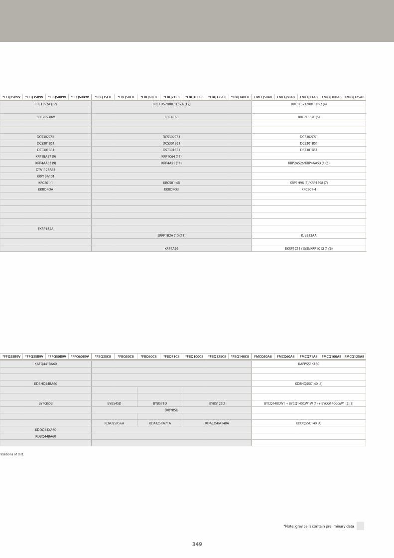
*FFQ25B9V *FFQ35B9V *FFQ50B9V *FFQ60B9V *FBQ35C8 *FBQ50C8 *FBQ60C8 *FBQ71C8 *FBQ100C8 *FBQ125C8 *FBQ140C8 FMCQ50A8 FMCQ60A8 FMCQ71A8 FMCQ100A8 FMCQ125A8
KAFQ441BA60 KAFP551K160
KDBHQ44BA60 KDBHQ55C140 (4)
BYFQ60B BYBS45D BYBS71D BYBS125D BYCQ140CW1 + BYCQ140CW1W (1) + BYCQ140CGW1 (2)(3)
EKBYBSD
KDAJ25K56A KDAJ25KA71A KDAJ25KA140A KDDQ55C140 (4)
KDDQ44XA60
KDBQ44BA60
ntrations of dirt.
*Note: grey cells contain preliminary data
*FFQ25B9V *FFQ35B9V *FFQ50B9V *FFQ60B9V *FBQ35C8 *FBQ50C8 *FBQ60C8 *FBQ71C8 *FBQ100C8 *FBQ125C8 *FBQ140C8 FMCQ50A8 FMCQ60A8 FMCQ71A8 FMCQ100A8 FMCQ125A8
BRC1E52A (12) BRC1D52/BRC1E52A (12) BRC1E52A/BRC1D52 (4)
BRC7E530W BRC4C65 BRC7F532F (5)
DCS302C51 DCS302C51 DCS302C51
DCS301B51 DCS301B51 DCS301B51
DST301B51 DST301B51 DST301B51
KRP1BA57 (9) KRP1C64 (11)
KRP4AA53 (9) KRP4A51 (11) KRP2A526/KRP4AA53 (1)(5)
DTA112BA51
KRP1BA101
KRCS01-1 KRCS01-4B KRP1H98 (5)/KRP1598 (7)
EKROROA EKRORO3 KRCS01-4
EKRP1B2A
EKRP1B2A (10)(11) KJB212AA
KRP4A96 EKRP1C11 (1)(5)/KRP1C12 (1)(6)
349
GC_pre2_lowres.pdf 349 30/11/2011 12:32:10
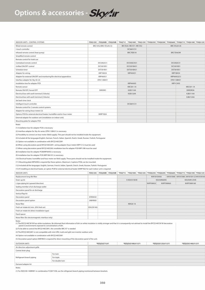
Options & accessories -
OUTDOOR UNITS *RZQ(S)G71LV1 *RZQ(S)G100LV1/LY1 *RZQ(S)G125LV1/LY1 *RZQ(S)G140LV1/LY1
Air direction adjustment grille
Central drain plug
Refrigerant branch piping
For twin
For triple
For double twin
Demand adapter kit
Notes
(1) For RZQ100-140B9W1 in combination FCQH71D8, use the refrigerant branch piping mentioned between brackets.
INDOOR UNITS - CONTROL SYSTEMS FDQ125C FDQ200B FDQ250B *FAQ71C *FAQ100C *FAQ125C *FHQG35C *FHQG50C *FHQG60C *FHQG71C *FHQG100C *FHQG125C
Wired remote control BRC1D52/BRC1E52A(12) BRC1E52A / BRC1E71 / BRC1D52 BRC1E52A (4)
I-touch controller DCS601CS1
Infrared remote control (heat pump) BRC7EB518 BRC7EA63W
Simplified remote control
Remote control for hotel use
Centralised remote control DCS302C51 DCS302CA51 DCS302C51
Unified ON/OFF control DCS301B51 DCS301BA51 DCS301B51
Schedule timer DST301B51 DST301BA51 DST301B51
Adapter for wiring KRP1BA54 KRP4AA51 KRP1BA54
Adapter for external ON/OFF and monitoring/for electrical appendices KRP4AA51 KRP4AA52(1)
Interface adapter for Sky Air (2) DTA112BA51 DTA112BA51
Installation box for adapter PCB KRP4AA93 KRP1CA93
Remote sensor KRCS01-1A KRCS01-1A
Remote ON/OFF, forced OFF EKRORO KJB311AA EKROROA
Electrical box with earth terminal (3 blocks) KJB312AA KJB311AA
Electrical box with earth terminal (2 blocks) KJB212AA
Set back time clock
Intelligent touch controller DCS601C51
Remote control for 2 remote control systems
Adapter for wiring (hour meter) (3)
Options PCB for external electrical heater, humidifier and/or hour meter EKRP1B2A
External adapter for outdoor unit (installation on indoor unit)
Mounting plate for adapter PCB
Notes
(1) Installation box for adapter PCB is necessary
(2) Interface adapter for Sky Air series (DTA112BA51) is necessary
(3) Possibility to connect an hour meter (field supply). This part should not be installed inside the equipment.
(4) Included all the languages:English, German, French, Italian, Spanish, Dutch, Greek, Russian, Turkish, Purtuguese
(5) Option not available in combination with BYCQ140CGW1
(6) When using decoration panel BYCQ140CGW1, wiring adapter (hour meter) KRP1C12 must be used
(7) When using decoration panel BYCQ140CGW, installation box for adapter PCB KRP1J98 must be used
(8) Installation box for adapter PCB(KRP4A95) is necessary
(9) Installation box for adapter PCB (KRP1BA101) is necessary
(10) Electrical heater, humidifier and hour meter are field supply. These parts should not be installed inside the equipment.
(11) Mounting plate KRP4A96 is required fpr these options. Maximum 2 options PCBs can be mounted.
(12) Included all the languages: English, German, French, Italian, Spanish, Dutch, Greek, Russian, Turkish. Portuguese
(13) If installing an electrical heater, an option PCB for external electrical heater (EKRP1B2) for each indoor unit is required
INDOOR UNITS FDQ125C FDQ200B FDQ250B *FAQ71C *FAQ100C *FAQ125C *FHQG35C *FHQG50C *FHQG60C *FHQG71C *FHQG100C *FHQG125C
Replacement long-life filter KAF501DA56 KAF501DA80 KAF501DA80 KAF501DA112 KAF501DA160
Drain-up kit K-KDU572EVE KDU50N60VE KDU50N125VE
L-type piping kit (upward direction) KHFP5MA35 KHFP5MA63 KHFP5MA160
Sealing member of air discharge outlet
Decoration panel for air discharge
Vertical flap kit
Decoration panel BYBSK5D
Decoration panel option EKBYBSD
Noise filter KEK26-1A
Fresh air intake kit (min. 20% fresh air) KDAJ25K140A
Fresh air intake kit (direct installation type)
Panel spacer
Noise filter (for electromagnetic interface only)
Notes(1) The BYCQ140CW1W has white insulations. Be informed that information of dirt on white insulation is visibly stronger and that it is consequently not advised to install the BYCQ140CW1W decoration
panel in environments exposed to concentrations of dirt.
(2) To be able to control the BYCQ140CGW1, the controller BRC1E* is needed
(3) The BYCQ140CGW1 is not compatible with mini-VRV, multi and split non inverter outdoor units
(4) Option not available in combination with BYCQ140CGW1
(5) Decoration panel option EKBYBSD is required for direct mounting of the decoration panel of the unit.
350
GC_pre2_lowres.pdf 350 30/11/2011 12:32:10
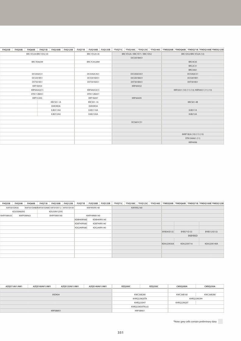
AZQS71AV1/AW1 AZQS100AV1/AW1 AZQS125AV1/AW1 AZQS140AV1/AW1 RZQ200C RZQ250C CMSQ200A CMSQ250A
EKDK04 KWC26B280 KWC26B160 KWC26B280
KHRQ22M20TA KHRQ22M29H
KHRQ250H7 KHRQ22M20T
KHRQ22M20TA(x3)
KRP58M51 KRP58M51
*Note: grey cells contain preliminary data
FHQ35B FHQ50B FHQ60B FHQ71B FHQ100B FHQ125B FUQ71B FUQ100B FUQ125B *FVQ71C *FVQ100C *FVQ125C *FVQ140C *FMDQ50B *FMDQ60B *FMDQ71B *FMDQ100B *FMDQ125B
BRC1E52A/BRC1D52 (4) BRC1E52A (4) BRC1E52A / BRC1E71 / BRC1D52 BRC1D52/BRC1E52A (12)
DCS301BAS1
BRC7EA63W BRC7CA528W BRC4C65
BRC2C51
BRC3A61
DCS302C51 DCS302CA51 DCS302CA51 DCS302C51
DCS301B51 DCS301BA51 DCS301BA51 DCS301B51
DST301B51 DST301BA51 DST301BA51 DST301B51
KRP1BA54 KRP4AA52
KRP4AA52(1) KRP4AA53(1) KRP2A51 (10) (11) (13) /KRP4A51 (11) (13)
DTA112BA51 DTA112BA51
KRP1CA93 KRP1BA97 KRP4AA95
KRCS01-1A KRCS01-1A KRCS01-4B
EKROROA EKROROA
KJB311AA KJB311AA KJB311A
KJB212AA KJB212AA KJB212A
DCS601C51
EKRP1B2A (10) (11) (13)
DTA104A61 (11)
KRP4A96
FHQ35B FHQ50B FHQ60B FHQ71B FHQ100B FHQ125B FUQ71B FUQ100B FUQ125B *FVQ71C *FVQ100C *FVQ125C *FVQ140C *FMDQ50B *FMDQ60B *FMDQ71B *FMDQ100B *FMDQ125B
KAF501DA56 KAF501DA80KAF501DA80 KAF501DA112 KAF501DA160 KAF495FA140 KAFJ95L160
KDU50N60VE KDU50N125VE
KHFP5MA35 KHFP5MA63 KHFP5MA160 KHFP49MA140
KDBH49FA80 KDBH49FA140
KDBT49FA80 KDBT49FA140
KDGJ49FA80 KDGJ49FA140
BYBS45D (5) BYBS71D (5) BYBS125D (5)
EKBYBSD
KDAJ25K56A KDAJ25K71A KDAJ25K140A
351
GC_pre2_lowres.pdf 351 30/11/2011 12:32:10
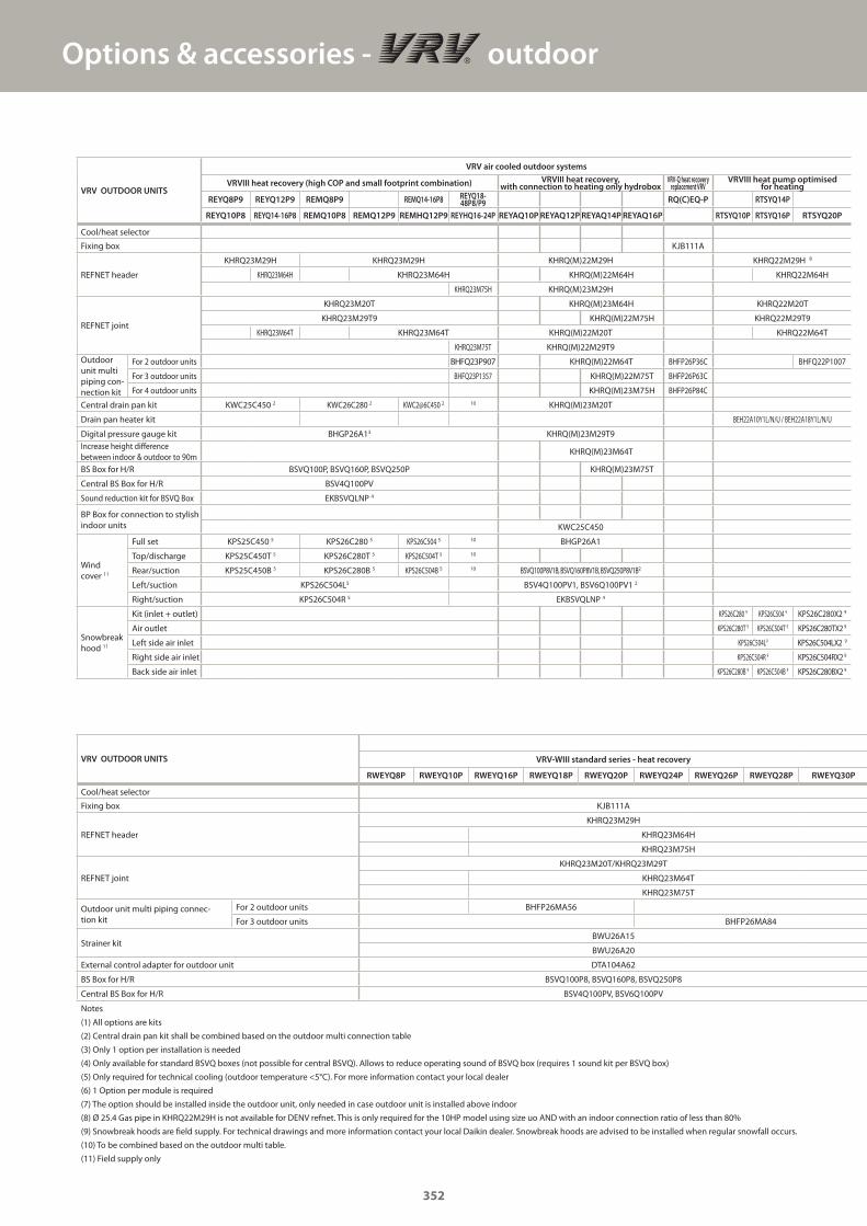
Options & accessories - outdoor
VRV OUTDOOR UNITS
VRV air cooled outdoor systems
VRVIII heat recovery (high COP and small footprint combination) VRVIII heat recovery, with connection to heating only hydrobox
VRV-Q heat recovery replacement VRV
VRVIII heat pump optimised for heating
REYQ8P9 REYQ12P9 REMQ8P9 REMQ14-16P8 REYQ18-48P8/P9 RQ(C)EQ-P RTSYQ14P
REYQ10P8 REYQ14-16P8 REMQ10P8 REMQ12P9 REMHQ12P9 REYHQ16-24P REYAQ10P REYAQ12P REYAQ14P REYAQ16P RTSYQ10P RTSYQ16P RTSYQ20P
Cool/heat selector
Fixing box KJB111A
REFNET header
KHRQ23M29H KHRQ23M29H KHRQ(M)22M29H KHRQ22M29H 8
KHRQ23M64H KHRQ23M64H KHRQ(M)22M64H KHRQ22M64H
KHRQ23M75H KHRQ(M)23M29H
REFNET joint
KHRQ23M20T KHRQ(M)23M64H KHRQ22M20T
KHRQ23M29T9 KHRQ(M)22M75H KHRQ22M29T9
KHRQ23M64T KHRQ23M64T KHRQ(M)22M20T KHRQ22M64T
KHRQ23M75T KHRQ(M)22M29T9Outdoor unit multi piping con-nection kit
For 2 outdoor units BHFQ23P907 KHRQ(M)22M64T BHFP26P36C BHFQ22P1007
For 3 outdoor units BHFQ23P1357 KHRQ(M)22M75T BHFP26P63C
For 4 outdoor units KHRQ(M)23M75H BHFP26P84C
Central drain pan kit KWC25C450 2 KWC26C280 2 KWC2@6C450 2 10 KHRQ(M)23M20T
Drain pan heater kit BEH22A10Y1L/N/U / BEH22A18Y1L/N/U
Digital pressure gauge kit BHGP26A13 KHRQ(M)23M29T9Increase height difference between indoor & outdoor to 90m
KHRQ(M)23M64T
BS Box for H/R BSVQ100P, BSVQ160P, BSVQ250P KHRQ(M)23M75T
Central BS Box for H/R BSV4Q100PV
Sound reduction kit for BSVQ Box EKBSVQLNP 4
BP Box for connection to stylish indoor units KWC25C450
Wind cover 11
Full set KPS25C450 5 KPS26C280 5 KPS26C504 5 10 BHGP26A1
Top/discharge KPS25C450T 5 KPS26C280T 5 KPS26C504T 5 10
Rear/suction KPS25C450B 5 KPS26C280B 5 KPS26C504B 5 10 BSVQ100P8V1B, BSVQ160P8V1B, BSVQ250P8V1B2
Left/suction KPS26C504L5 BSV4Q100PV1, BSV6Q100PV1 2
Right/suction KPS26C504R 5 EKBSVQLNP 4
Snowbreak hood 11
Kit (inlet + outlet) KPS26C280 9 KPS26C504 9 KPS26C280X2 9
Air outlet KPS26C280T 9 KPS26C504T 9 KPS26C280TX2 9
Left side air inlet KPS26C504L9 KPS26C504LX2 9
Right side air inlet KPS26C504R 9 KPS26C504RX2 9
Back side air inlet KPS26C280B 9 KPS26C504B 9 KPS26C280BX2 9
VRV OUTDOOR UNITS VRV-WIII standard series - heat recovery
RWEYQ8P RWEYQ10P RWEYQ16P RWEYQ18P RWEYQ20P RWEYQ24P RWEYQ26P RWEYQ28P RWEYQ30P
Cool/heat selector
Fixing box KJB111A
REFNET header
KHRQ23M29H
KHRQ23M64H
KHRQ23M75H
REFNET joint
KHRQ23M20T/KHRQ23M29T
KHRQ23M64T
KHRQ23M75T
Outdoor unit multi piping connec-tion kit
For 2 outdoor units BHFP26MA56
For 3 outdoor units BHFP26MA84
Strainer kitBWU26A15
BWU26A20
External control adapter for outdoor unit DTA104A62
BS Box for H/R BSVQ100P8, BSVQ160P8, BSVQ250P8
Central BS Box for H/R BSV4Q100PV, BSV6Q100PV
Notes
(1) All options are kits
(2) Central drain pan kit shall be combined based on the outdoor multi connection table
(3) Only 1 option per installation is needed
(4) Only available for standard BSVQ boxes (not possible for central BSVQ). Allows to reduce operating sound of BSVQ box (requires 1 sound kit per BSVQ box)
(5) Only required for technical cooling (outdoor temperature <5°C). For more information contact your local dealer
(6) 1 Option per module is required
(7) The option should be installed inside the outdoor unit, only needed in case outdoor unit is installed above indoor
(8) Ø 25.4 Gas pipe in KHRQ22M29H is not available for DENV refnet. This is only required for the 10HP model using size uo AND with an indoor connection ratio of less than 80%
(9) Snowbreak hoods are field supply. For technical drawings and more information contact your local Daikin dealer. Snowbreak hoods are advised to be installed when regular snowfall occurs.
(10) To be combined based on the outdoor multi table.
(11) Field supply only
352
GC_pre2_lowres.pdf 352 30/11/2011 12:32:10
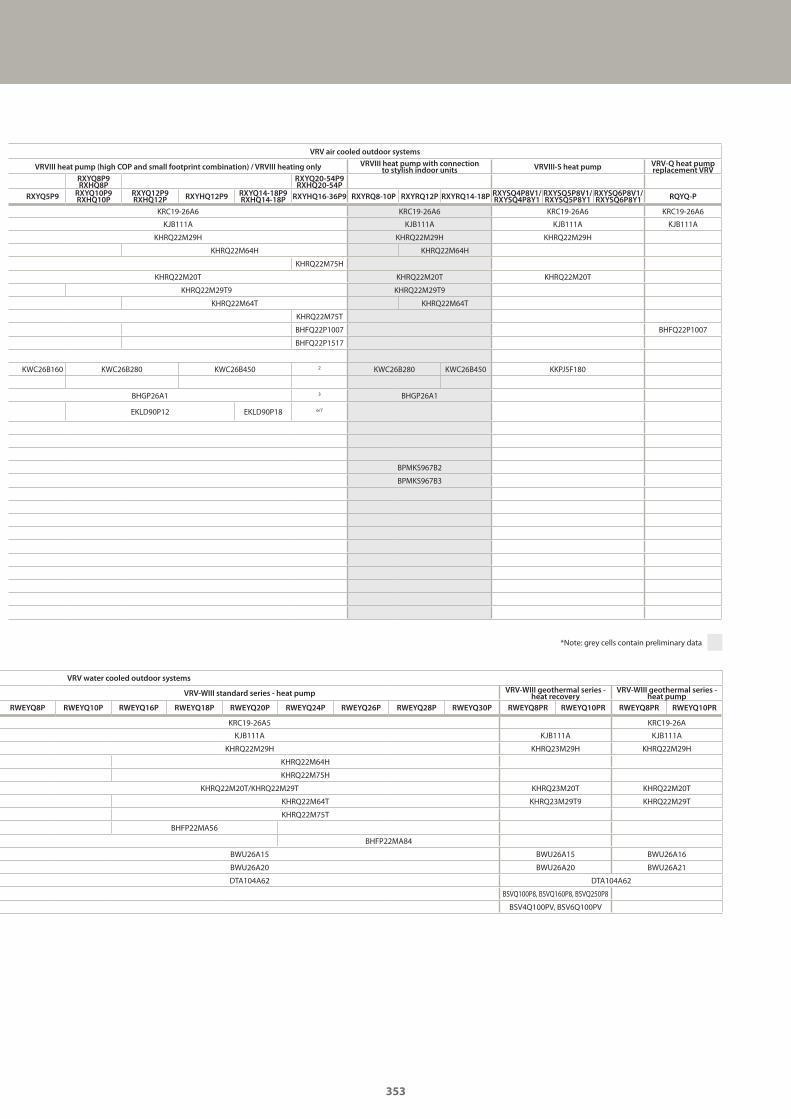
VRV air cooled outdoor systems
VRVIII heat pump (high COP and small footprint combination) / VRVIII heating only VRVIII heat pump with connection to stylish indoor units VRVIII-S heat pump VRV-Q heat pump
replacement VRVRXYQ8P9RXHQ8P
RXYQ20-54P9RXHQ20-54P
RXYQ5P9 RXYQ10P9RXHQ10P
RXYQ12P9RXHQ12P RXYHQ12P9 RXYQ14-18P9
RXHQ14-18P RXYHQ16-36P9 RXYRQ8-10P RXYRQ12P RXYRQ14-18P RXYSQ4P8V1/RXYSQ4P8Y1
RXYSQ5P8V1/RXYSQ5P8Y1
RXYSQ6P8V1/RXYSQ6P8Y1 RQYQ-P
KRC19-26A6 KRC19-26A6 KRC19-26A6 KRC19-26A6
KJB111A KJB111A KJB111A KJB111A
KHRQ22M29H KHRQ22M29H KHRQ22M29H
KHRQ22M64H KHRQ22M64H
KHRQ22M75H
KHRQ22M20T KHRQ22M20T KHRQ22M20T
KHRQ22M29T9 KHRQ22M29T9
KHRQ22M64T KHRQ22M64T
KHRQ22M75T
BHFQ22P1007 BHFQ22P1007
BHFQ22P1517
KWC26B160 KWC26B280 KWC26B450 2 KWC26B280 KWC26B450 KKPJ5F180
BHGP26A1 3 BHGP26A1
EKLD90P12 EKLD90P18 6/7
BPMKS967B2
BPMKS967B3
VRV water cooled outdoor systems
VRV-WIII standard series - heat pump VRV-WIII geothermal series - heat recovery
VRV-WIII geothermal series - heat pump
RWEYQ8P RWEYQ10P RWEYQ16P RWEYQ18P RWEYQ20P RWEYQ24P RWEYQ26P RWEYQ28P RWEYQ30P RWEYQ8PR RWEYQ10PR RWEYQ8PR RWEYQ10PR
KRC19-26A5 KRC19-26A
KJB111A KJB111A KJB111A
KHRQ22M29H KHRQ23M29H KHRQ22M29H
KHRQ22M64H
KHRQ22M75H
KHRQ22M20T/KHRQ22M29T KHRQ23M20T KHRQ22M20T
KHRQ22M64T KHRQ23M29T9 KHRQ22M29T
KHRQ22M75T
BHFP22MA56
BHFP22MA84
BWU26A15 BWU26A15 BWU26A16
BWU26A20 BWU26A20 BWU26A21
DTA104A62 DTA104A62
BSVQ100P8, BSVQ160P8, BSVQ250P8
BSV4Q100PV, BSV6Q100PV
*Note: grey cells contain preliminary data
353
GC_pre2_lowres.pdf 353 30/11/2011 12:32:11
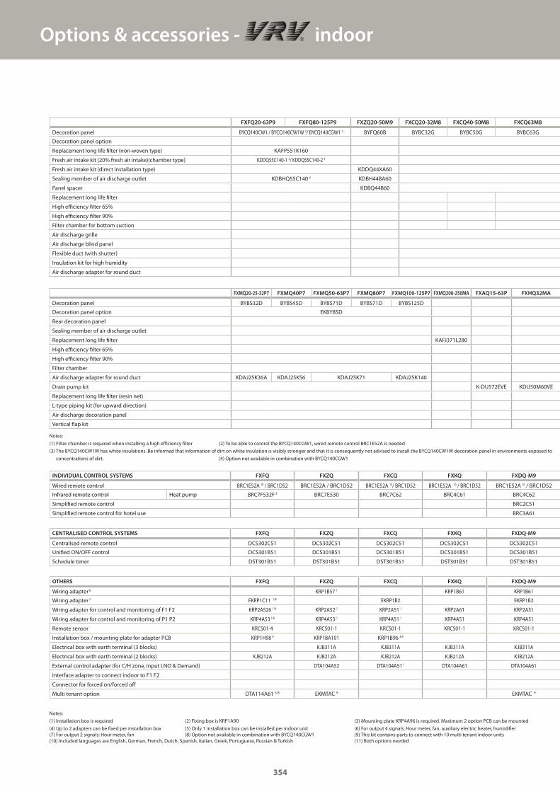
Options & accessories - indoor
Notes:
(1) Filter chamber is required when installing a high efficiency filter (2) To be able to control the BYCQ140CGW1, wired remote control BRC1E52A is needed
(3) The BYCQ140CW1W has white insulations. Be informed that information of dirt on white insulation is visibly stronger and that it is consequently not advised to install the BYCQ140CW1W decoration panel in environments exposed to
concentrations of dirt. (4) Option not available in combination with BYCQ140CGW1
Notes:
(1) Installation box is required (2) Fixing box is KRP1A90 (3) Mounting plate KRP4A96 is required. Maximum 2 option PCB can be mounted
(4) Up to 2 adapters can be fixed per installation box (5) Only 1 installation box can be installed per indoor unit (6) For output 4 signals: Hour meter, fan, auxiliary electric heater, humidifier(7) For output 2 signals: Hour meter, fan (8) Option not available in combination with BYCQ140CGW1 (9) This kit contains parts to connect with 10 multi tenant indoor units(10) Included languages are English, German, French, Dutch, Spanish, Italian, Greek, Portuguese, Russian & Turkish (11) Both options needed
OTHERS FXFQ FXZQ FXCQ FXKQ FXDQ-M9
Wiring adapter 6 KRP1B57 1 KRP1B61 KRP1B61
Wiring adapter 7 EKRP1C11 1/8 EKRP1B2 EKRP1B2
Wiring adapter for control and monitoring of F1 F2 KRP2A526 1/8 KRP2A52 1 KRP2A51 1 KRP2A61 KRP2A51
Wiring adapter for control and monitoring of P1 P2 KRP4A53 1/8 KRP4A53 1 KRP4A51 1 KRP4A51 KRP4A51
Remote sensor KRCS01-4 KRCS01-1 KRCS01-1 KRCS01-1 KRCS01-1
Installation box / mounting plate for adapter PCB KRP1H98 8 KRP1BA101 KRP1B96 4/5
Electrical box with earth terminal (3 blocks) KJB311A KJB311A KJB311A KJB311A
Electrical box with earth terminal (2 blocks) KJB212A KJB212A KJB212A KJB212A KJB212A
External control adapter (for C/H zone, input LNO & Demand) DTA104A52 DTA104A51 1 DTA104A61 DTA104A61
Interface adapter to connect indoor to F1 F2
Connector for forced on/forced off
Multi tenant option DTA114A61 3/8 EKMTAC 9 EKMTAC 9
INDIVIDUAL CONTROL SYSTEMS FXFQ FXZQ FXCQ FXKQ FXDQ-M9
Wired remote control BRC1E52A 10 / BRC1D52 BRC1E52A / BRC1D52 BRC1E52A 10/ BRC1D52 BRC1E52A 10 / BRC1D52 BRC1E52A 10 / BRC1D52
Infrared remote control Heat pump BRC7F532F 8 BRC7E530 BRC7C62 BRC4C61 BRC4C62
Simplified remote control BRC2C51
Simplified remote control for hotel use BRC3A61
CENTRALISED CONTROL SYSTEMS FXFQ FXZQ FXCQ FXKQ FXDQ-M9
Centralised remote control DCS302C51 DCS302C51 DCS302C51 DCS302C51 DCS302C51
Unified ON/OFF control DCS301B51 DCS301B51 DCS301B51 DCS301B51 DCS301B51
Schedule timer DST301B51 DST301B51 DST301B51 DST301B51 DST301B51
FXFQ20-63P9 FXFQ80-125P9 FXZQ20-50M9 FXCQ20-32M8 FXCQ40-50M8 FXCQ63M8
Decoration panel BYCQ140CW1 / BYCQ140CW1W 3/ BYCQ140CGW1 2 BYFQ60B BYBC32G BYBC50G BYBC63G
Decoration panel option
Replacement long life filter (non-woven type) KAFP551K160
Fresh air intake kit (20% fresh air intake)(chamber type) KDDQ55C140-1 4/ KDDQ55C140-2 4
Fresh air intake kit (direct installation type) KDDQ44XA60
Sealing member of air discharge outlet KDBHQ55C140 4 KDBH44BA60
Panel spacer KDBQ44B60
Replacement long life filter
High efficiency filter 65%
High efficiency filter 90%
Filter chamber for bottom suction
Air discharge grille
Air discharge blind panel
Flexible duct (with shutter)
Insulation kit for high humidity
Air discharge adapter for round duct
FXMQ20-25-32P7 FXMQ40P7 FXMQ50-63P7 FXMQ80P7 FXMQ100-125P7 FXMQ200-250MA FXAQ15-63P FXHQ32MA
Decoration panel BYBS32D BYBS45D BYBS71D BYBS71D BYBS125D
Decoration panel option EKBYBSD
Rear decoration panel
Sealing member of air discharge outlet
Replacement long life filter KAFJ371L280
High efficiency filter 65%
High efficiency filter 90%
Filter chamber
Air discharge adapter for round duct KDAJ25K36A KDAJ25K56 KDAJ25K71 KDAJ25K140
Drain pump kit K-DU572EVE KDU50M60VE
Replacement long life filter (resin net)
L-type piping kit (for upward direction)
Air discharge decoration panel
Vertical flap kit
354
GC_pre2_lowres.pdf 354 30/11/2011 12:32:11
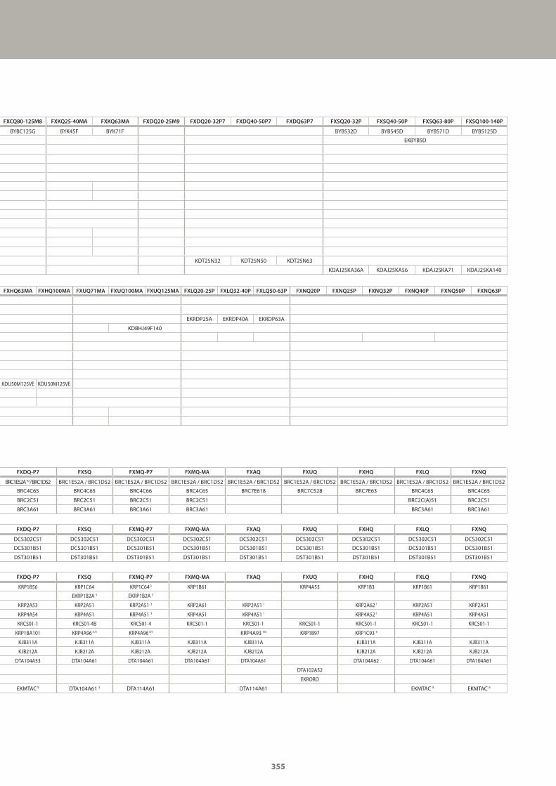
FXDQ-P7 FXSQ FXMQ-P7 FXMQ-MA FXAQ FXUQ FXHQ FXLQ FXNQ
KRP1B56 KRP1C64 KRP1C64 3 KRP1B61 KRP4A53 KRP1B3 KRP1B61 KRP1B61
EKRP1B2A 3 EKRP1B2A 3
KRP2A53 KRP2A51 KRP2A51 3 KRP2A61 KRP2A51 1 KRP2A62 1 KRP2A51 KRP2A51
KRP4A54 KRP4A51 KRP4A51 3 KRP4A51 KRP4A51 1 KRP4A52 1 KRP4A51 KRP4A51
KRCS01-1 KRCS01-4B KRCS01-4 KRCS01-1 KRCS01-1 KRCS01-1 KRCS01-1 KRCS01-1 KRCS01-1
KRP1BA101 KRP4A96 4 /5 KRP4A96 4/5 KRP4A93 4/5 KRP1B97 KRP1C93 4
KJB311A KJB311A KJB311A KJB311A KJB311A KJB311A KJB311A KJB311A
KJB212A KJB212A KJB212A KJB212A KJB212A KJB212A KJB212A KJB212A
DTA104A53 DTA104A61 DTA104A61 DTA104A61 DTA104A61 DTA104A62 DTA104A61 DTA104A61
DTA102A52
EKRORO
EKMTAC 9 DTA104A61 3 DTA114A61 DTA114A61 EKMTAC 9 EKMTAC 9
FXDQ-P7 FXSQ FXMQ-P7 FXMQ-MA FXAQ FXUQ FXHQ FXLQ FXNQ
BRC1E52A 10 / BRC1D52 BRC1E52A / BRC1D52 BRC1E52A / BRC1D52 BRC1E52A / BRC1D52 BRC1E52A / BRC1D52 BRC1E52A / BRC1D52 BRC1E52A / BRC1D52 BRC1E52A / BRC1D52 BRC1E52A / BRC1D52
BRC4C65 BRC4C65 BRC4C66 BRC4C65 BRC7E618 BRC7C528 BRC7E63 BRC4C65 BRC4C65
BRC2C51 BRC2C51 BRC2C51 BRC2C51 BRC2C(A)51 BRC2C51
BRC3A61 BRC3A61 BRC3A61 BRC3A61 BRC3A61 BRC3A61
FXDQ-P7 FXSQ FXMQ-P7 FXMQ-MA FXAQ FXUQ FXHQ FXLQ FXNQ
DCS302C51 DCS302C51 DCS302C51 DCS302C51 DCS302C51 DCS302C51 DCS302C51 DCS302C51 DCS302C51
DCS301B51 DCS301B51 DCS301B51 DCS301B51 DCS301B51 DCS301B51 DCS301B51 DCS301B51 DCS301B51
DST301B51 DST301B51 DST301B51 DST301B51 DST301B51 DST301B51 DST301B51 DST301B51 DST301B51
FXCQ80-125M8 FXKQ25-40MA FXKQ63MA FXDQ20-25M9 FXDQ20-32P7 FXDQ40-50P7 FXDQ63P7 FXSQ20-32P FXSQ40-50P FXSQ63-80P FXSQ100-140P
BYBC125G BYK45F BYK71F BYBS32D BYBS45D BYBS71D BYBS125D
EKBYBSD
KDT25N32 KDT25N50 KDT25N63
KDAJ25KA36A KDAJ25KA56 KDAJ25KA71 KDAJ25KA140
FXHQ63MA FXHQ100MA FXUQ71MA FXUQ100MA FXUQ125MA FXLQ20-25P FXLQ32-40P FXLQ50-63P FXNQ20P FXNQ25P FXNQ32P FXNQ40P FXNQ50P FXNQ63P
EKRDP25A EKRDP40A EKRDP63A
KDBHJ49F140
KDU50M125VE KDU50M125VE
355
GC_pre2_lowres.pdf 355 30/11/2011 12:32:11
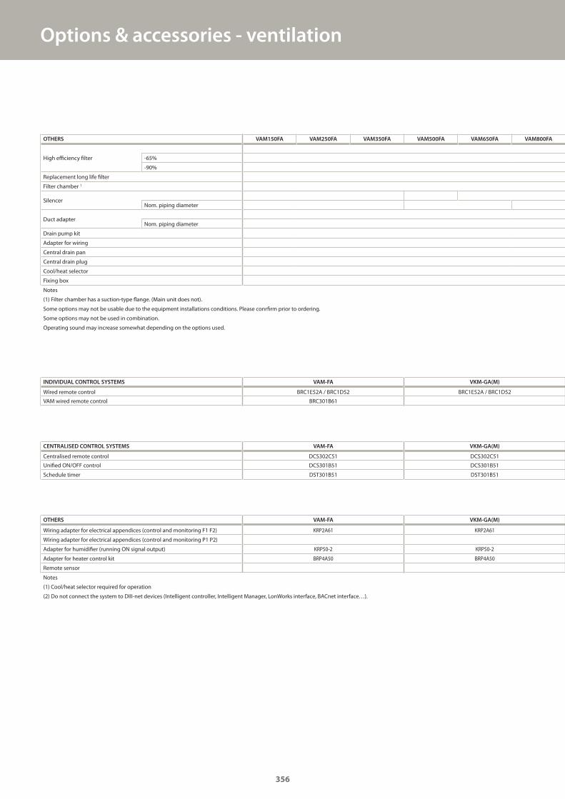
Options & accessories - ventilation
OTHERS VAM-FA VKM-GA(M)
Wiring adapter for electrical appendices (control and monitoring F1 F2) KRP2A61 KRP2A61
Wiring adapter for electrical appendices (control and monitoring P1 P2)
Adapter for humidifier (running ON signal output) KRP50-2 KRP50-2
Adapter for heater control kit BRP4A50 BRP4A50
Remote sensor
Notes
(1) Cool/heat selector required for operation
(2) Do not connect the system to DIII-net devices (Intelligent controller, Intelligent Manager, LonWorks interface, BACnet interface…).
OTHERS VAM150FA VAM250FA VAM350FA VAM500FA VAM650FA VAM800FA
High efficiency filter -65%
-90%
Replacement long life filter
Filter chamber 1
SilencerNom. piping diameter
Duct adapterNom. piping diameter
Drain pump kit
Adapter for wiring
Central drain pan
Central drain plug
Cool/heat selector
Fixing box
Notes
(1) Filter chamber has a suction-type flange. (Main unit does not).
Some options may not be usable due to the equipment installations conditions. Please conrfirm prior to ordering.
Some options may not be used in combination.
Operating sound may increase somewhat depending on the options used.
INDIVIDUAL CONTROL SYSTEMS VAM-FA VKM-GA(M)
Wired remote control BRC1E52A / BRC1D52 BRC1E52A / BRC1D52
VAM wired remote control BRC301B61
CENTRALISED CONTROL SYSTEMS VAM-FA VKM-GA(M)
Centralised remote control DCS302C51 DCS302C51
Unified ON/OFF control DCS301B51 DCS301B51
Schedule timer DST301B51 DST301B51
356
GC_pre2_lowres.pdf 356 30/11/2011 12:32:11
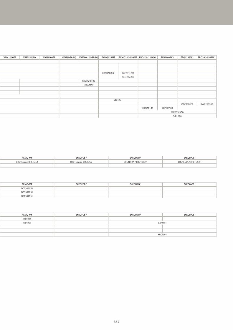
FXMQ-MF EKEQFCB 2 EKEQDCB 2 EKEQMCB 2
KRP2A61
KRP4A51 KRP4A51
KRCS01-1
VAM1000FA VAM1500FA VAM2000FA VKM50GA(M) VKM80-100GA(M) FXMQ125MF FXMQ200-250MF ERQ100-125AV1 ERW140AV1 ERQ125AW1 ERQ200-250AW1
KAFJ371L140 KAFJ371L280
KDJ3705L280
KDDM24B100
ø250mm
KRP1B61
KWC26B160 KWC26B280
KKPJ5F180 KKPJ5F180
KRC19-26A6
KJB111A
FXMQ-MF EKEQFCB 2 EKEQDCB 2 EKEQMCB 2
BRC1E52A / BRC1D52 BRC1E52A / BRC1D52 BRC1E52A / BRC1D52 1 BRC1E52A / BRC1D52 1
FXMQ-MF EKEQFCB 2 EKEQDCB 2 EKEQMCB 2
DCS302C51
DCS301B51
DST301B51
357
GC_pre2_lowres.pdf 357 30/11/2011 12:32:11
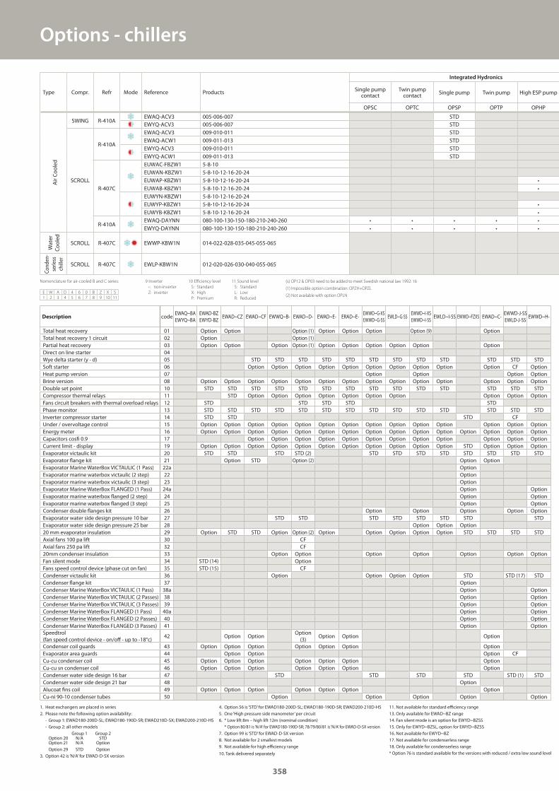
Options - chillers
Description codeEWAQ~BAEWYQ~BA
EWAD-BZEWYD-BZ
EWAD~CZ EWAD~CF EWWQ~B- EWAD~D- EWAD~E- ERAD~E-EWWD~G-XSEWWD~G-SS
EWLD~G-SSEWWD~I-XSEWWD~I-SS
EWLD~I-SS EWWD~FZXS EWAD~C-EWWD-J-SSEWLD-J-SS
EWWD~H-
Total heat recovery 01 Option Option Option (1) Option Option Option Option (9) OptionTotal heat recovery 1 circuit 02 Option Option (1)Partial heat recovery 03 Option Option Option Option (1) Option Option Option Option Option OptionDirect on line starter 04Wye delta starter (y - d) 05 STD STD STD STD STD STD STD STD STD STD STD STDSoft starter 06 Option Option Option Option Option Option Option Option Option Option CF OptionHeat pump version 07 Option Option Option OptionBrine version 08 Option Option Option Option Option Option Option Option Option Option Option Option Option OptionDouble set point 10 STD STD STD STD STD STD STD STD STD STD STD STD STD STDCompressor thermal relays 11 STD Option Option Option Option Option Option Option Option Option OptionFans circuit breakers with thermal overload relays 12 STD STD STD STD STDPhase monitor 13 STD STD STD STD STD STD STD STD STD STD STD STD STD STDInverter compressor starter 14 STD STD STD CFUnder / overvoltage control 15 Option Option Option Option Option Option Option Option Option Option Option Option Option OptionEnergy meter 16 Option Option Option Option Option Option Option Option Option Option Option Option Option Option OptionCapacitors cosfi 0.9 17 Option Option Option Option Option Option Option Option Option Option Option OptionCurrent limit - display 19 Option Option Option Option Option Option Option Option Option Option Option STD Option Option OptionEvaporator victaulic kit 20 STD STD STD STD (2) STD STD STD STD STD STD STD STDEvaporator flange kit 21 Option STD Option (2) Option OptionEvaporator Marine WaterBox VICTAULIC (1 Pass) 22a OptionEvaporator marine waterbox victaulic (2 step) 22 OptionEvaporator marine waterbox victaulic (3 step) 23 OptionEvaporator Marine WaterBox FLANGED (1 Pass) 24a Option OptionEvaporator marine waterbox flanged (2 step) 24 Option OptionEvaporator marine waterbox flanged (3 step) 25 Option OptionCondenser double flanges kit 26 Option Option Option Option OptionEvaporator water side design pressure 10 bar 27 STD STD STD STD STD STD STD STDEvaporator water side design pressure 25 bar 28 Option Option Option20 mm evaporator insulation 29 Option STD STD Option Option (2) Option Option Option Option Option STD STD STD STDAxial fans 100 pa lift 30 CFAxial fans 250 pa lift 32 CF20mm condenser insulation 33 Option Option Option Option Option Option OptionFan silent mode 34 STD (14) OptionFans speed control device (phase cut on fan) 35 STD (15) CFCondenser victaulic kit 36 Option Option Option Option STD STD (17) STDCondenser flange kit 37 OptionCondenser Marine WaterBox VICTAULIC (1 Pass) 38a Option OptionCondenser Marine WaterBox VICTAULIC (2 Passes) 38 Option OptionCondenser Marine WaterBox VICTAULIC (3 Passes) 39 Option OptionCondenser Marine WaterBox FLANGED (1 Pass) 40a Option OptionCondenser Marine WaterBox FLANGED (2 Passes) 40 Option OptionCondenser Marine WaterBox FLANGED (3 Passes) 41 Option OptionSpeedtrol (fan speed control device - on/off - up to -18°c)
42 Option OptionOption
(3)Option Option Option
Condenser coil guards 43 Option Option Option Option Option Option OptionEvaporator area guards 44 Option Option Option CFCu-cu condenser coil 45 Option Option Option Option Option Option OptionCu-cu sn condenser coil 46 Option Option Option Option Option Option OptionCondenser water side design 16 bar 47 STD STD STD STD STD (1) STDCondenser water side design 21 bar 48 OptionAlucoat fins coil 49 Option Option Option Option Option Option OptionCu-ni 90-10 condenser tubes 50 Option Option Option Option Option
1. Heat exchangers are placed in series2. Please note the following option availability: - Group 1: EWAD180-200D-SL; EWAD180-190D-SR; EWAD210D-SX; EWAD200-210D-HS - Group 2: all other models Group 1 Group 2 Option 20 N/A STD Option 21 N/A Option Option 29 STD Option3. Option 42 is ‘N/A’ for EWAD-D-SX version
Nomenclature for air-cooled B and C series:
E W A D 4 6 0 B Z X S
1 2 3 4 5 6 7 8 9 10 11
9 Inverter
-: non-inverter
Z: inverter
10 Efficiency level
S: Standard
X: High
P: Premium
11 Sound level
S: Standard
L: Low
R: Reduced
(s) OP12 & OP03 need to be added to meet Swedish national law 1992: 16
(1) Impossible option combination: OPZH+OPZL
(2) Not available with option OPLN
4. Option 56 is ‘STD’ for EWAD180-200D-SL; EWAD180-190D-SR; EWAD200-210D-HS5. One ‘High pressure side manometer’ per circuit6. * Low lift 8m – high lift 12m (nominal condition) * Option 80/81 is ‘N/A’ for EWAD180-190D-SR; 78/79/80/81 is ‘N/A’ for EWAD-D-SX version7. Option 99 is ‘STD’ for EWAD-D-SX version8. Not available for 2 smallest models9. Not available for high efficiency range
10. Tank delivered separately
11. Not available for standard efficiency range13. Only available for EWAD~BZ range14. Fan silent mode is an option for EWYD~BZSS15. Only for EWYD~BZSL, option for EWYD~BZSS16. Not available for EWYD~BZ17. Not available for condenserless range18. Only available for condenserless range* Option 76 is standard available for the versions with reduced / extra low sound level
Type Compr. Refr Mode Reference Products
Integrated Hydronics
Single pump contact
Twin pump contact Single pump Twin pump High ESP pump
OPSC OPTC OPSP OPTP OPHP
Air Coo
led
SWING R-410AEWAQ-ACV3 005-006-007 STDEWYQ-ACV3 005-006-007 STD
SCROLL
R-410A
EWAQ-ACV3 009-010-011 STDEWAQ-ACW1 009-011-013 STDEWYQ-ACV3 009-010-011 STDEWYQ-ACW1 009-011-013 STD
R-407C
EUWAC-FBZW1 5-8-10EUWAN-KBZW1 5-8-10-12-16-20-24EUWAP-KBZW1 5-8-10-12-16-20-24 •EUWAB-KBZW1 5-8-10-12-16-20-24 •EUWYN-KBZW1 5-8-10-12-16-20-24EUWYP-KBZW1 5-8-10-12-16-20-24 •EUWYB-KBZW1 5-8-10-12-16-20-24 •
R-410AEWAQ-DAYNN 080-100-130-150-180-210-240-260 • • • • •EWYQ-DAYNN 080-100-130-150-180-210-240-260 • • • • •
Water
Coo
led
SCROLL R-407C EWWP-KBW1N 014-022-028-035-045-055-065
Cond
en-
serle
ss
chiller
SCROLL R-407C EWLP-KBW1N 012-020-026-030-040-055-065
358
GC_pre2_lowres.pdf 358 30/11/2011 12:32:11
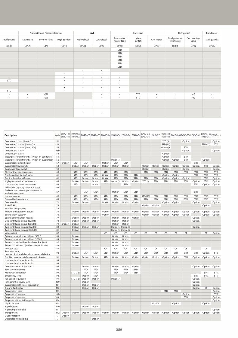
Noise & Head Pressure Control LWE Electrical Refrigerant Condenser
Buffer tank Low noise Inverter fans High ESP fans High Glycol Low Glycol Evaporator heater tape
Main switch A / V meter Dual pressure
relief valveSuction stop
valve Coil guards
OPBT OPLN OPIF OPHF OPZH OPZL OP10 OP52 OP57 OP03 OP12 OPCG
STDSTDSTDSTDSTDSTD
• •• • • •• • • •
STD • • • •• • • •• • • •
STD • • • •• • •(2) • • STD • • •(s) •• • •(2) • • STD • • •(s) •
• •
• •
Description codeEWAQ~BAEWYQ~BA
EWAD-BZEWYD-BZ
EWAD~CZ EWAD~CF EWWQ~B- EWAD~D- EWAD~E- ERAD~E-EWWD~G-XSEWWD~G-SS
EWLD~G-SSEWWD~I-XSEWWD~I-SS
EWLD~I-SS EWWD~FZXS EWAD~C-EWWD-J-SSEWLD-J-SS
EWWD~H-
Condenser 1 pass (dt 4-8 °c) 51 STD (9) Option OptionCondenser 2 passes (dt 4-8 °c) 52 STD (11) STD (17) STDCondenser 2 passes (dt 9-15 °c) 53 Option (9) STDCondenser 3 passes 53b Option OptionCondenser 4 passes 54 OptionWater pressure differential switch on condenser 55 Option STDWater pressure differential switch on evaporator 56 Option (4) Option Option STD OptionEvaporator electric heater 57 Option STD STD Option STD STD STDEvaporator flow switch 58 Option Option Option Option Option Option Option Option Option Option Option Option STD OptionCondenser flow switch 59 Option Option Option OptionElectronic expansion device 60 STD STD STD STD STD STD STD STD STD STD STD STD STD STDDischarge line shut off valve 61 STD STD STD Option STD STD STD Option Option STD STD STDSuction line shut off valve 62 STD Option Option Option STD STD STD STD STD Option Option Option STD OptionHigh pressure side manometers 63 Option Option Option STD Option (5) Option Option STD (9) STD STD STD STD Option STD OptionLow pressure side manometers 64 STD Option STD STD Option OptionAdditional capacity reduction steps 65Ambient outside temperature sensor and set-point reset
67 STD STD Option STD STD STD
Hour run meter 68 STD STD STD STD STD STD STD STD (11) STD STD STD STD STD STD STDGeneral fault contactor 69 STD STD STD STD STD STD STD STD STD STD STD STD STD STD STDContainer kit 71 Option Option Option Option Option Option Option Option Option OptionFork-lift kit 72 Option Option OptionWooden box packing 74Rubber anti vibration mount 75 Option Option Option Option Option Option Option Option Option Option Option Option Option Option OptionSound proof system* 76 Option Option Option Option Option Option Option OptionSpring anti vibration mount 77 Option Option Option Option Option Option OptionOne centrifugal pump (low lift) 78 Option Option Option Option Option OptionOne centrifugal pump (high lift) 79 Option Option Option OptionTwo centrifugal pumps (low lift) 80 Option Option Option Option (6) Option (8) OptionTwo centrifugal pumps (high lift) 81 Option Option (6) Option (8)Witness test 82 CF CF CF CF CF CF CF CF CF CF OptionExternal tank without cabinet (500 l) 83 Option Option OptionExternal tank without cabinet (1000 l) 84 Option Option OptionExternal tank (500 l) with cabinet RAL7032 87 Option Option OptionExternal tank (1000 l) with cabinet RAL7032 88 Option Option OptionAcoustic test 89 CF CF CF CF CF CF CF CF CF CFSet-point reset, demand limit and alarm from external device
90 Option STD STD STD Option STD STD STD STD STD STD STD STD Option STD
Double pressure relief valve with diverter 91 Option Option Option STD Option Option Option Option Option Option Option STD Option Option OptionLow ambient kit for 1 circuit 93Low ambient kit for 2 circuits 94Compressor circuit breakers 95 Option Option Option Option Option Option Option OptionFans circuit breakers 96 STD STD STD STD STDMain switch interlock 97 STD (16) STD STD STD STD STD STD STDEmergency stop 98 Option STD STD STD STDFan speed regulation 99 STD (16) Option Option Option (7) OptionRefrigerant recovery tank 100 Option OptionEvaporator right water connection 101 Option Option OptionGround fault relay 102 Option Option Option CF OptionEvaporator 1pass 103 STD STD OptionEvaporator 2 passes 103a Option STDEvaporator 3 passes 103b STD OptionEvaporator Double Flange Kit 104 OptionLiquid receiver 105 Option Option OptionRapid restart 110 Option OptionHigh temperature kit 111 OptionTransport kit 112 Option Option Option Option Option Option Option Option Option Option Option Option Option Option Option OptionGlycol function .. OptionOptimized free cooling .. Option
359
GC_pre2_lowres.pdf 359 30/11/2011 12:32:11
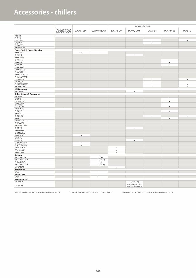
Accessories - chillers
Air cooled chillers
EWA/YQ009-011ACV3EWA/YQ009-013ACW1 EUWAC-FBZW1 EUWA/Y*-KBZW1 EWA/YQ~BA* EWA/YQ-DAYN EWAD~D- EWA(Y)D~BZ EWAD~C-
Panels
EKDSSPEKDSSP-S*** • •EKDDSP •EKPWPROEKPWPROMSerial Cards & Comm. Modules
EKAC10C • •EKACPG •EKAC200AEKAC200J •EKACBAC •EKACLON •EKACLONPEKACRS232EKACWEBEKACBACMSTPEKACBACCERTEKCM200J • •EKCMLON • •EKCMBACMSTP • •EKCMBACIP • •LON Gateway
EKLONPG •Other Systems & Accessories
EKCLWSEKCON •EKCONUSB •EKMODEM •EKGSMOD •EKRP1HB •EKRUPCJ •EKRUPCKEKRUPCS • •EKPV2J •EKPWPROEXTEKGWWEBEKGWMODEMEKBNPG •EKBMSBNAEKBMSMBAEKRUMCA •EKRUPCEKRUPG •EHMC*AV1010 •EHMC*AV1080 •EKRP1AHTA •DTA104A62 •EKRUAHTB •Gauges
EKGAU5/8KA • (5-8)EKGAU10/12KA • (10-12)EKGAU16KA • (16)EKGAU20/24KA • (20-24)BHGP26A1 •Soft starter
EKSS •Buffer tank
EKBT •Waterpipe kit
EKGN210 • (080-210)
EKGN260 • (EWAQ240-260DAYN& EWYQ230-250DAYN)
* To install EKRUMCA => EKAC10C needs to be installed on the unit. * EKAC10C allows direct connection to MODBUS BMS system * To install EKLONPG & EKBNPG => EKACPG needs to be installed on the unit.
360
GC_pre2_lowres.pdf 360 30/11/2011 12:32:12
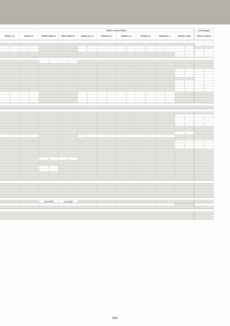
Water cooled chillers Centrifugals
EWAD~CZ EWAD-CF EWWP-KBW1N EWLP-KBW1N EWW(L)D~G- EWW(L)D~I- EWWD~H- EWWQ~B- EWW(L)D~J- EWWD~FZXS DWSC & DWDC
•• • • • • • • •• • • • • • • • •
• •• •
• •
• •• •• •
•• •• •• •• •
• • • • • • •• • • • • • •• • • • • • •• • • • • • •
• •• •• •• •
•• • • • • • •
• •• •• •
• •
••
• (014-045) • (012-030)
361
GC_pre2_lowres.pdf 361 30/11/2011 12:32:12
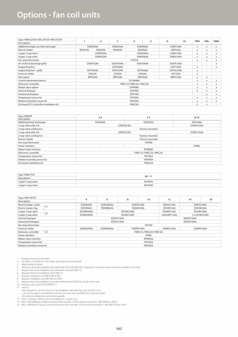
Options - fan coil units
Type: FWM-DT/DF, FWL-DT/DF, FWV-DT/DF1 2 3 4 6 8 10 FWV FWL FWM
Description
Additional single row heat exchanger ESRH02A6 ESRH03A6 ESRH06A6 ESRH10A6 x x xElectric heater EEH01A6 EEH02A6 EEH03A6 EEH06A6 EEH10A6 x x x2-pipe 3-way valve E2MV03A6 E2MV06A6 E2MV10A6 x x x4-pipe 3-way valve E4MV03A6 E4MV06A6 E4MV10A6 x x xFan stop thermostat YFSTA6 x x xAir intake & discharge grille EAIDF02A6 EAIDF03A6 EAIDF06A6 EAIDF10A6 - - xSupporting feet ESFV06A6 ESFV10A6 x - xSupporting feet + grille ESFVG2A6 ESFVG3A6 ESFVG6A6 ESFVG10A6 x - -Fresh air intake EFA2A6 EFA3A6 EFA6A6 EFA10A6 x - -Rear panel ERPV2A6 ERPV3A6 ERPV6A6 ERPV10A6 x x -Control electromechanical ECFWMB6 x x xElectronic controller FWEC1A, FWEC2A, FWEC3A x x xMaster slave option EPIMSB6 x x xVertical drainpan EDPVA6 x x xHorizontal drainpan EDPHA6 - x xTemperature sensor kit FWTSKA x x xRelative humidity sensor kit FWHSKA x x xOn board FCU controller installation kit FWECKA x x -
1. Requires electronic controller
2. For FWD 12,16,18AT/AF only motor valve (piping not included)
3. Water probe included
4. Optional, electrical installation box with earth terminal KJB212A is required, if controller wires need to be installed in the wall.
5. Requires electrical installation box with earth terminal KJB311A.
6. Requires electrical installation box KJB411A.
7. Requires installation box KRP1H98. (FWC)
8. Requires installation box KRP1BA101 (FWF)
9. Requires electrical installation box with earth terminal KJB212A, if built in the wall.
10. Requires valve control PCB EKRP1C11
11. I-touch:
• Not allowed to use the i-touch for an installation with both fan coils and VRV units.
• Can not be used in combination with fan coil units, that use MOD bus communication.
• No Airnet or telephone connection possible.
12. Only 1 of these 4 options can be installed on 1 indoor unit.
13. Max. 1 KRP1H98 box can be mounted on the unit. Max. 2 PCB’s can be mounted in 1 KRP1H98 box. (FWC)
14. Max. 2 KRP1BA101 boxes can be mounted on the unit. Max. 1PCB can be mounted in 1 KRP1BA101 box. (FWF)
Type: FWD-AT/AF4 6 8 10 12 16 18
Description
Electric heater: small(1)
EDEH04A6 EDEHS06A6 EDEHS10A6 EDEHS12A6 EDEHS18A6Electric heater: big EDEH04A6 EDEHB06A6 EDEHB10A6 EDEHB12A6 EDEHB18A62-pipe 3-way valve
(2)ED2MV04A6 ED2MV10A6 ED2MV12A6 ED2MV18A6
4-pipe 3-way valve ED4MV04A6 ED4MV10A6 2xED2MV12A6 2 x ED2MV18A6Vertical Drainpan EDDPV10A6 EDDPV18A6Horizontal Drainpan EDDPH10A6 EDDPH18A6Fan stop thermostat YFSTA6Fresh air intake EDMFA04A6 EDMFA06A6 EDMFA10A6 EDMFA12A6 EDMFA18A6Electronic controller (3) FWEC1A, FWEC2A, FWEC3APower interface EPIB6Master slave interface EPIMSA6Temperature sensor kit FWTSKARelative humidity sensor kit FWHSKA
Type: FWB-BT2-4 5-7 8-10
DescriptionAdditional heat exchanger EAH04A6 EAH07A6 EAH10A63-way valve add. h/e E2MV307A6 E2MV310A63-way valve cooling h/e Factory mounted2-way valve add. h/e E2MV207A6 E2MV210A62-way valve cooling h/e Factory mountedElectric Heater Factory mountedFan stop thermostat YFSTA6Power interface - - EPIB6Master slave interface EPIMSB6Electronic controller FWEC1A, FWEC2A, FWEC2ATemperature sensor kit FWTSKARelative humidity sensor kit FWHSKAOn board installation kit FWECKA
Type: FWB-JT/JF02 - 11
Description
2-pipe 3-way valve MCWCN
4-pipe 3-way valve MCWHN
362
GC_pre2_lowres.pdf 362 30/11/2011 12:32:12
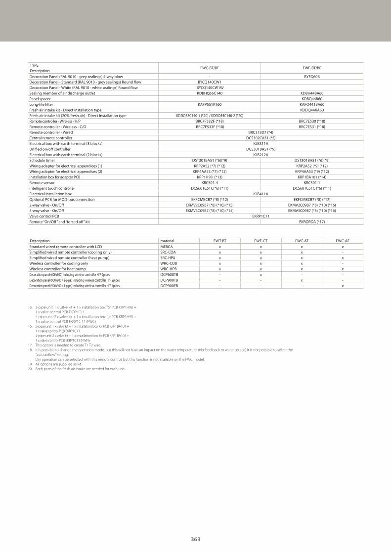
TYPEFWC-BT/BF FWF-BT/BF
Description
Decoration Panel (RAL 9010 - grey sealings) 4-way blow - BYFQ60BDecoration Panel - Standard (RAL 9010 - grey sealings) Round flow BYCQ140CW1Decoration Panel - White (RAL 9010 - white sealings) Round flow BYCQ140CW1WSealing member of air discharge outlet KDBHQ55C140 KDBH44BA60Panel spacer - KDBQ44B60Long-life filter KAFP551K160 KAFQ441BA60Fresh air intake kit - Direct installation type - KDDQ44XA60Fresh air intake kit (20% fresh air) - Direct installation type KDDQ55C140-1 (*20) / KDDQ55C140-2 (*20) -Remote controller - Wireless - H/P BRC7F532F (*18) BRC7E530 (*18)Remote controller - Wireless - C/O BRC7F533F (*18) BRC7E531 (*18)Remote controller - Wired BRC315D7 (*4)Central remote controller DCS302CA51 (*5)Electrical box with earth terminal (3 blocks) KJB311AUnified on/off controller DCS301BA51 (*9)Electrical box with earth terminal (2 blocks) KJB212ASchedule timer DST301BA51 (*6)(*9) DST301BA51 (*6)(*9)Wiring adapter for electrical appendices (1) KRP2A52 (*7) (*12) KRP2A52 (*9) (*12)Wiring adapter for electrical appendices (2) KRP4AA53 (*7) (*12) KRP4AA53 (*9) (*12)Installation box for adapter PCB KRP1H98 (*13) KRP1BA101 (*14)Remote sensor KRCS01-4 KRCS01-1Intelligent touch controller DCS601C51C(*6) (*11) DCS601C51C (*6) (*11)Electrical installation box KJB411AOptional PCB for MOD-bus connection EKFCMBCB7 (*8) (*12) EKFCMBCB7 (*8) (*12)2-way valve - On/Off EKMV2C09B7 (*8) (*10) (*15) EKMV2C09B7 (*8) (*10) (*16)3-way valve - On/Off EKMV3C09B7 (*8) (*10) (*15) EKMV3C09B7 (*8) (*10) (*16)Valve control PCB EKRP1C11Remote “On/Off” and “forced off” kit EKROROA (*17)
Description material FWT-BT FWF-CT FWC-AT FWC-AF
Standard wired remote controller with LCD MERCA x x x xSimplified wired remote controller (cooling only) SRC-COA x x x -Simplified wired remote controller (heat pump) SRC-HPA x x x xWireless controller for cooling only WRC-COB x x x -Wireless controller for heat pump WRC-HPB x x x xDecoration panel (600x600) including wireless controller H/P 2pipes DCP600TB - x - -Decoration panel (900x900 / 2-pipe) including wireless controller H/P 2pipes DCP900TB - - x -Decoration panel (900x900 / 4-pipe) including wireless controller H/P 4pipes DCP900FB - - - x
15. 2-pipe unit: 1 x valve kit + 1 x installation box for PCB KRP1H98 +
1 x valve control PCB EKRP1C11
4-pipe unit: 2 x valve kit + 1 x installation box for PCB KRP1H98 +
1 x valve control PCB EKRP1C 11 (FWC)
16. 2-pipe unit: 1 x valve kit + 1 x installation box for PCB KRP1BA101 +
1 x valve control PCB EKRP1C11
4-pipe unit: 2 x valve kit + 1 x installation box for PCB KRP1BA101 +
1 x valve control PCB EKRP1C11 (FWF)»
17. This option is needed to create T1 T2 wire.
18. It is possible to change the operation mode, but this will not have an impact on the water temperature. (No feed back to water source) It is not possible to select the
“auto airflow” setting.
Dry operation can be selected with this remote control, but this function is not available on the FWC model.
19. All options are supplied as kit.
20. Both parts of the fresh air intake are needed for each unit.
363
GC_pre2_lowres.pdf 363 30/11/2011 12:32:12
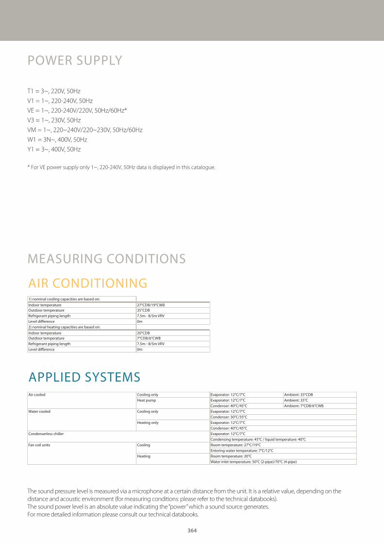
AIR CONDITIONING1) nominal cooling capacities are based on:
Indoor temperature 27°CDB/19°CWBOutdoor temperature 35°CDBRefrigerant piping length 7.5m - 8/5m VRVLevel difference 0m2) nominal heating capacities are based on:
Indoor temperature 20°CDBOutdoor temperature 7°CDB/6°CWBRefrigerant piping length 7.5m - 8/5m VRVLevel difference 0m
APPLIED SYSTEMSAir cooled Cooling only Evaporator: 12°C/7°C Ambient: 35°CDB
Heat pump Evaporator: 12°C/7°C Ambient: 35°CCondenser: 40°C/45°C Ambient: 7°CDB/6°CWB
Water cooled Cooling only Evaporator: 12°C/7°CCondenser: 30°C/35°C
Heating only Evaporator: 12°C/7°CCondenser: 40°C/45°C
Condenserless chiller Evaporator: 12°C/7°CCondensing temperature: 45°C / liquid temperature: 40°C
Fan coil units Cooling Room temperature: 27°C/19°CEntering water temperature: 7°C/12°C
Heating Room temperature: 20°CWater inlet temperature: 50°C (2-pipe)/70°C (4-pipe)
POWER SUPPLY
T1 = 3~, 220V, 50Hz
V1 = 1~, 220-240V, 50Hz
VE = 1~, 220-240V/220V, 50Hz/60Hz*
V3 = 1~, 230V, 50Hz
VM = 1~, 220~240V/220~230V, 50Hz/60Hz
W1 = 3N~, 400V, 50Hz
Y1 = 3~, 400V, 50Hz
MEASURING CONDITIONS
* For VE power supply only 1~, 220-240V, 50Hz data is displayed in this catalogue.
The sound pressure level is measured via a microphone at a certain distance from the unit. It is a relative value, depending on the
distance and acoustic environment (for measuring conditions: please refer to the technical databooks).
The sound power level is an absolute value indicating the “power” which a sound source generates.
For more detailed information please consult our technical databooks.
364
GC_pre2_lowres.pdf 364 30/11/2011 12:32:12