Angelo Baggini (University of Bergamo) (ECD) · PDF fileAngelo Baggini (University of Bergamo)...
20
Discussion Paper Angelo Baggini (University of Bergamo) Francesco Buratti (ECD) Matteo Granziero (Socomec UPS) Under Review Power Quality Power Quality Classification of electrical installations in healthcare facilities according to reliability and availability of power supply μC
Transcript of Angelo Baggini (University of Bergamo) (ECD) · PDF fileAngelo Baggini (University of Bergamo)...
Discussion Paper
Angelo Baggini (University of Bergamo)
Francesco Buratti (ECD)
Matteo Granziero (Socomec UPS)
Under Review
Po
wer Q
uality
Power Quality
Classification of electrical installations in healthcare facilities according to reliability
and availability of power supply
μC
2
http://www.leonardo-energy.org
Index1. Executive Summary . . . . . . . . . . . . . . . . . . . . . . . . . . . . . . . . . . . . . . . . . . . . . . . . . . . . . . 3
2. Purpose of this White Paper . . . . . . . . . . . . . . . . . . . . . . . . . . . . . . . . . . . . . . . . . . . . . . . . 3
3. The Standard approach : IEC 60364-7-710 requirements . . . . . . . . . . . . . . . . . . . . . . . . . . . . . 4
3.1. Scope . . . . . . . . . . . . . . . . . . . . . . . . . . . . . . . . . . . . . . . . . . . . . . . . . . . . . . . . . . . . . . . . 4
3.2. Medical location classifi cation . . . . . . . . . . . . . . . . . . . . . . . . . . . . . . . . . . . . . . . . . . . . . . . . 4
3.3. Types of system earthing and safety requirements . . . . . . . . . . . . . . . . . . . . . . . . . . . . . . . . . . . 5
3.4. Emergency supply . . . . . . . . . . . . . . . . . . . . . . . . . . . . . . . . . . . . . . . . . . . . . . . . . . . . . . . . 5
3.5. Equipment requirements . . . . . . . . . . . . . . . . . . . . . . . . . . . . . . . . . . . . . . . . . . . . . . . . . . . 5
3.6. Verifi cations . . . . . . . . . . . . . . . . . . . . . . . . . . . . . . . . . . . . . . . . . . . . . . . . . . . . . . . . . . . . 5
4. Assessing the existing situation . . . . . . . . . . . . . . . . . . . . . . . . . . . . . . . . . . . . . . . . . . . . . . 6
4.1. Description of the study/research methodology . . . . . . . . . . . . . . . . . . . . . . . . . . . . . . . . . . . . . 6
4.2. Overview of main problems and needs surfaced during interviews . . . . . . . . . . . . . . . . . . . . . . . . 7
4.2.1. Proper UPS sizing . . . . . . . . . . . . . . . . . . . . . . . . . . . . . . . . . . . . . . . . . . . . . . . . . . . . . . . . 7
4.2.2. Periodic tests . . . . . . . . . . . . . . . . . . . . . . . . . . . . . . . . . . . . . . . . . . . . . . . . . . . . . . . . . . . 7
4.2.3. Mutual infl uences between medical devices . . . . . . . . . . . . . . . . . . . . . . . . . . . . . . . . . . . . . . . 7
4.2.4. Patients’ quality of life . . . . . . . . . . . . . . . . . . . . . . . . . . . . . . . . . . . . . . . . . . . . . . . . . . . . . . 7
4.2.5. Doctors’ and nurses’ training . . . . . . . . . . . . . . . . . . . . . . . . . . . . . . . . . . . . . . . . . . . . . . . . . 7
4.3. Overall requirements for delivering medical services . . . . . . . . . . . . . . . . . . . . . . . . . . . . . . . . . . 7
4.3.1. Power quality requirements for medical devices . . . . . . . . . . . . . . . . . . . . . . . . . . . . . . . . . . . . . 7
4.3.2. Power quality requirements for other loads . . . . . . . . . . . . . . . . . . . . . . . . . . . . . . . . . . . . . . . . 8
4.3.3. Requirements for patients’ quality of life . . . . . . . . . . . . . . . . . . . . . . . . . . . . . . . . . . . . . . . . . . 10
5. Building a resiliency level classifi cation for medical facilities . . . . . . . . . . . . . . . . . . . . . . . . . . 10
5.1. Patient’s quality of life categories . . . . . . . . . . . . . . . . . . . . . . . . . . . . . . . . . . . . . . . . . . . . . . 10
5.2. Leonardo Energy Healthcare facilities resiliency level identifi cation . . . . . . . . . . . . . . . . . . . . . . . . 11
6. Best practices . . . . . . . . . . . . . . . . . . . . . . . . . . . . . . . . . . . . . . . . . . . . . . . . . . . . . . . . . . 13
6.1. Tests, when standards are not enough . . . . . . . . . . . . . . . . . . . . . . . . . . . . . . . . . . . . . . . . . . . 13
6.2. Design criteria . . . . . . . . . . . . . . . . . . . . . . . . . . . . . . . . . . . . . . . . . . . . . . . . . . . . . . . . . . 14
6.2.1. Neutral conductor systems . . . . . . . . . . . . . . . . . . . . . . . . . . . . . . . . . . . . . . . . . . . . . . . . . . 14
6.2.2. Installation equipment . . . . . . . . . . . . . . . . . . . . . . . . . . . . . . . . . . . . . . . . . . . . . . . . . . . . . 14
6.2.3. Distribution schemes . . . . . . . . . . . . . . . . . . . . . . . . . . . . . . . . . . . . . . . . . . . . . . . . . . . . . . 17
6.2.4. Redundancy . . . . . . . . . . . . . . . . . . . . . . . . . . . . . . . . . . . . . . . . . . . . . . . . . . . . . . . . . . . . 18
6.3. Personnel training . . . . . . . . . . . . . . . . . . . . . . . . . . . . . . . . . . . . . . . . . . . . . . . . . . . . . . . . 19
7. Conclusions . . . . . . . . . . . . . . . . . . . . . . . . . . . . . . . . . . . . . . . . . . . . . . . . . . . . . . . . . . . 20
8. References . . . . . . . . . . . . . . . . . . . . . . . . . . . . . . . . . . . . . . . . . . . . . . . . . . . . . . . . . . . . 20
DISCLAIMER:While this document has been prepared with care, European Copper Institute and other contributers provide no warranty with regards to the content and shall not be liable for any direct, incidental or consequential damages that may result from the use of the information or the data contained.
Power Quality
3
http://www.leonardo-energy.org
1. Executive SummaryCommon electrical disturbances can cause high-tech medical equipment to malfunction. As medical equipment
is often connected to vulnerable patients, such a malfunction can easily result in serious problems.
International standards for medical installations focus primarily on safety, in particular on protection against indirect
contact. For example, standard IEC 60364-7-710 classifi es medical locations into three groups - 0, 1 and 2 - on the basis
of the type of contact between the applied parts and the patient.
Currently, the requirements defi ning the availability of supply, reliability of supply and the power supply’s infrastruc-
ture’s resiliency to disturbances are merely qualitative. There is a need for a universally accepted defi nition of these
three parameters. To guarantee the right performance level of electrical installations in healthcare facilities, both the
safety of supply and the quality of supply need to be considered with equal importance.
Patient safety is the prime reason for minimizing equipment malfunction and its consequences. But healthcare facili-
ties administrators also need to consider the economical aspects. Electrical disturbances can result in diagnostic tests
needing to be repeated, an increase in medical supply waste and/or expensive service and repair calls. A recent study
carried out by Leonardo ENERGY to assess the costs related to power quality problems concluded that inadequate
power supplies can vastly increase a hospital’s operational costs.
In addition to the costs related to labour and equipment repairs, there is the loss of a patient’s quality of life, which
is impossible to quantify in monetary terms. Often medical equipment incorporates sensitive electronic power sup-
plies and microprocessors. Apart from safety aspects, malfunctions can result in patient discomfort and misdiag-
noses.
Through direct interviews carried out by the authors of this paper it emerges that the current technical standards are
considered – almost unanimously – to be inadequate to guarantee the safety, reliability and availability of electricity
supplies. After defi ning the real user needs and analysing the interview results, the IEC classifi cation of medical loca-
tions has been extended to include the following aspects:
– Availability, resiliency and reliability of supply (i.e. quality of supply)
– The patient’s quality of life
This new approach aims to provide decision makers with an eff ective tool for the specifi cation of electrical instal-
lations in hospitals. Combining safety aspects with requirements for power quality reduces operating costs and
improves the patient’s quality of life.
2. Purpose of this White PaperThe design of electrical installations for hospitals increases in complexity with the size and the level of care delivered
by the facility. Special requirements have to be met since lives are at stake.
For the design of electrical installations in hospitals, the most important factor is the reliability of supply and its resil-
iency to disturbances. Every eff ort must be made to reduce the probability of equipment failure due to loss of power
from the electricity network and from internal emergency power sources.
Through a statistical approach in combination with fi eld work, we have developed a classifi cation scheme for func-
tionality in medical locations. This approach could provide a basis for future standardization activity in this fi eld.
Current design practice mainly considers the cost and safety aspects. The new classifi cation scheme will stimulate
a process based on all the relevant key issues, in particular the quality of supply parameters power quality (PQ), which
are often given too little attention and often at too late a stage.
Classifi cation of electrical installations in healthcare facilities according to reliability and availability of power supply
4
http://www.leonardo-energy.org
Head Physician Hospital Engineers
Administration
Director
Hospital Engineers Installation
Approval
Definition Head Physician
Administration
Director
Hospital Engineers
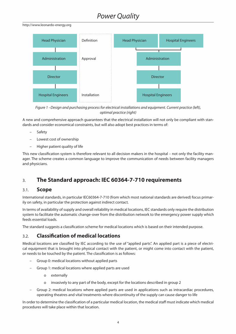
Figure 1 –Design and purchasing process for electrical installations and equipment. Current practice (left),
optimal practice (right)
A new and comprehensive approach guarantees that the electrical installation will not only be compliant with stan-
dards and consider economical constraints, but will also adopt best practices in terms of:
– Safety
– Lowest cost of ownership
– Higher patient quality of life
This new classifi cation system is therefore relevant to all decision makers in the hospital – not only the facility man-
ager. The scheme creates a common language to improve the communication of needs between facility managers
and physicians.
3. The Standard approach: IEC 60364-7-710 requirements
3.1. ScopeInternational standards, in particular IEC60364-7-710 (from which most national standards are derived) focus primar-
ily on safety, in particular the protection against indirect contact.
In terms of availability of supply and overall reliability in medical locations, IEC standards only require the distribution
system to facilitate the automatic change-over from the distribution network to the emergency power supply which
feeds essential loads.
The standard suggests a classifi cation scheme for medical locations which is based on their intended purpose.
3.2. Classifi cation of medical locationsMedical locations are classifi ed by IEC according to the use of “applied parts”. An applied part is a piece of electri-
cal equipment that is brought into physical contact with the patient, or might come into contact with the patient,
or needs to be touched by the patient. The classifi cation is as follows:
– Group 0: medical locations without applied parts
– Group 1: medical locations where applied parts are used
o externally
o invasively to any part of the body, except for the locations described in group 2
– Group 2: medical locations where applied parts are used in applications such as intracardiac procedures,
operating theatres and vital treatments where discontinuity of the supply can cause danger to life
In order to determine the classifi cation of a particular medical location, the medical staff must indicate which medical
procedures will take place within that location.
Power Quality
5
http://www.leonardo-energy.org
3.3. System earthing and safety requirementsIn each medical location of group 1 and group 2, supplementary equipotential bonding conductors must be installed
and connected to the equipotential bonding bus bar for the purpose of equalizing potential diff erences between
protective conductors and extraneous conductive parts located in the “patient environment”.
The TN-C system is not allowed in medical locations and medical buildings downstream of the main distribution
board.
In group 2 locations, the IT earthing arrangement (hereinafter referred to as “medical IT”) must be used for circuits
supplying medical electrical equipment and systems intended for life support, surgical applications and other electri-
cal equipment located in the “patient environment”.
3.4. Emergency supplyRegarding the continuity of supply in medical locations, secure power supplies are classifi ed on the basis of change-
over time required by the service they supervise:
– Power supplies with a changeover period less than or equal to 0.5 s
Secure power supply which is capable of maintaining operating theatre table lights and other essential
luminaires, e.g. endoscopes, for a minimum period of 3 hours and with a changeover period not exceed-
ing 0.5 s.
– Power supplies with a changeover period less than or equal to 15 s
Secure power supply for equipment which must be connected within 15 s for a minimum period of 24 hours,
when the voltage of one or more line conductors at the main distribution board for the critical services has
decreased by more than 10% of the nominal value of supply voltage for a duration greater than 3 s.
– Power supplies with a changeover period greater than 15 s
Used for equipment required for the maintenance of hospital services, which may be connected either auto-
matically or manually for a minimum period of 24 hours. This includes, for example, sterilization equipment,
air conditioning, heating and ventilation systems.
3.5. Equipment requirementsIEC requires that in the event of a mains power failure, a minimum illuminance level must be provided from a secure
supply within a changeover period not exceeding 15 s in the following locations:
– Escape routes
– Rooms in which essential services are provided
– Rooms of group 1 and 2 medical locations
Services other than lighting which require a secure supply within a changeover period not exceeding 15 s include
fi re protection systems and medical electrical equipment used in group 2 medical locations. Such equipment needs
to be identifi ed by responsible staff .
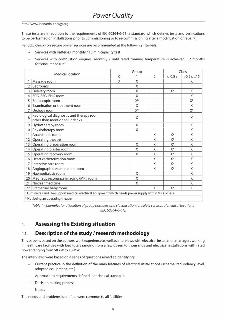
The standard also provides a table listing the secure power supply requirements for diff erent medical locations.
It’s important to note that a defi nitive list of medical locations showing their assigned groups is impracticable, as the
use of locations diff ers between countries and even within a country.
3.6. Verifi cationIEC 60364-7-710 defi nes the following tests to be carried out for locations belonging to group 1 and 2:
– Functional test of insulation on monitoring devices of medical IT systems
– Verifi cation of equipotential bonding
– Verifi cation of secure power service
– Measurement of leakage current of medical IT transformers in no-load condition
Classifi cation of electrical installations in healthcare facilities according to reliability and availability of power supply
6
http://www.leonardo-energy.org
These tests are in addition to the requirements of IEC 60364-6-61 (a standard which defi nes tests and verifi cations
to be performed on installations prior to commissioning or to re-commissioning after a modifi cation or repair).
Periodic checks on secure power services are recommended at the following intervals:
– Services with batteries: monthly / 15 min capacity test
– Services with combustion engines: monthly / until rated running temperature is achieved; 12 months
for “endurance run”
Medical locationGroup Class
0 1 2 ≤ 0,5 s >0,5 s ≤15
1 Massage room X X X
2 Bedrooms X
3 Delivery room X Xa X
4 ECG, EEG, EHG room X X
5 Endoscopic room Xb Xb
6 Examination or treatment room X X
7 Urology room Xb Xb
8Radiological diagnostic and therapy room,
other than mentioned under 21X X
9 Hydrotherapy room X X
10 Physiotherapy room X X
11 Anaesthetic room X Xa X
12 Operating theatre X Xa X
13 Operating preparation room X X Xa X
14 Operating plaster room X X Xa X
15 Operating recovery room X X Xa X
16 Heart catheterization room X Xa X
17 Intensive care room X Xa X
18 Angiographic examination room X Xa X
19 Haemodialysis room X X
20 Magnetic resonance imaging (MRI) room X X
21 Nuclear medicine X X
22 Premature baby room X Xa Xa Luminaires and life-support medical electrical equipment which needs power supply within 0.5 s or less
b Not being an operating theatre
Table 1 - Examples for allocation of group numbers and classifi cation for safety services of medical locations
(IEC 60364-6-61).
4. Assessing the Existing situation
4.1. Description of the study / research methodologyThis paper is based on the authors’ work experience as well as interviews with electrical installation managers working
in healthcare facilities with bed totals ranging from a few dozen to thousands and electrical installations with rated
power ranging from 50 kW to 10 MW.
The interviews were based on a series of questions aimed at identifying:
– Current practice in the defi nition of the main features of electrical installations (scheme, redundancy level,
adopted equipment, etc.)
– Approach to requirements defi ned in technical standards
– Decision making process
– Needs
The needs and problems identifi ed were common to all facilities.
Power Quality
7
http://www.leonardo-energy.org
4.2. Overview of main problems and needs identifi ed during interviews
4.2.1. Proper UPS sizing
UPS units are designed to supply energy to linear or non-linear loads having a crest factor of 3:1.
A UPS modifi es the characteristics of the electrical installation, such as:
– Short circuit power and current
– Impedance
– Protection coordination criteria
– Neutral system
– Electromagnetic emissions and immunity
The UPS is an autonomous power source inside the facility and it must be installed following the requirements
defi ned in the IEC standard.
Considering the electricity needs of medical facilities usually exceed typical UPS supply capacity and their require-
ments are very often more restrictive than elsewhere, the choice of UPS size must be made by applying accurate and
specifi c criteria.
4.2.2. Periodic tests
The periodic tests required by the IEC standard are satisfactory in terms of the nature of the test, but not good enough
in terms of the frequency of the tests (i.e. how often they are carried out).
4.2.3. Mutual infl uences between medical devices
The proper operation of medical devices depends on several factors, including the quality of the electrical supply.
X-Ray based machines, magnetic resonance imaging (MRI) and nuclear medicine devices are sensitive to voltage and
frequency variations. But X-Ray machines are also the most important source of electrical pollution because of their
intense and distorted high currents.
Medical equipment representing a dynamic load to the electrical system can cause power quality problems for the
entire facility.
Electrical disturbances can enter healthcare equipment through any electrical port: not only via the AC power input,
but also through communication ports.
4.2.4. Patients’ quality of life
The correct functioning of electrical equipment is linked to a patient’s quality of life, since it can:
– Minimise the repetition of examinations and the associated stress
– Prevent accidents caused by the improper use of medical devices
Moreover, the patients quality of life can be improved by providing them clear instructions on what to do in case
of abnormal electrical supply.
4.2.5. Doctors’ and nurses’ training
Hospital personnel generally lack knowledge on both electrical safety and power quality phenomena. This may
cause risky behaviour in the operating theatre or improper use of medical devices such as electro-surgery equip-
ment.
4.3. Overall requirements for delivering medical services
4.3.1. Power quality requirements for medical devices
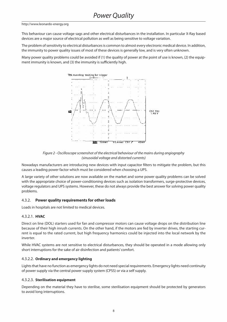
X-Ray based devices, MRI systems, CT scanners and linear accelerators typically absorb currents with high crest factor
and very steep wave fronts (see Figure 2).
Classifi cation of electrical installations in healthcare facilities according to reliability and availability of power supply
8
http://www.leonardo-energy.org
This behaviour can cause voltage sags and other electrical disturbances in the installation. In particular X-Ray based
devices are a major source of electrical pollution as well as being sensitive to voltage variation.
The problem of sensitivity to electrical disturbances is common to almost every electronic medical device. In addition,
the immunity to power quality issues of most of these devices is generally low, and is very often unknown.
Many power quality problems could be avoided if (1) the quality of power at the point of use is known, (2) the equip-
ment immunity is known, and (3) the immunity is suffi ciently high.
Figure 2 - Oscilloscope screenshot of the electrical behaviour of the mains during angiography
(sinusoidal voltage and distorted currents)
Nowadays manufacturers are introducing new devices with input capacitor fi lters to mitigate the problem, but this
causes a leading power factor which must be considered when choosing a UPS.
A large variety of other solutions are now available on the market and some power quality problems can be solved
with the appropriate choice of power-conditioning devices such as isolation transformers, surge-protective devices,
voltage regulators and UPS systems. However, these do not always provide the best answer for solving power quality
problems.
4.3.2. Power quality requirements for other loads
Loads in hospitals are not limited to medical devices.
4.3.2.1. HVAC
Direct on line (DOL) starters used for fan and compressor motors can cause voltage drops on the distribution line
because of their high inrush currents. On the other hand, if the motors are fed by inverter drives, the starting cur-
rent is equal to the rated current, but high frequency harmonics could be injected into the local network by the
inverter.
While HVAC systems are not sensitive to electrical disturbances, they should be operated in a mode allowing only
short interruptions for the sake of air disinfection and patients’ comfort.
4.3.2.2. Ordinary and emergency lighting
Lights that have no function as emergency lights do not need special requirements. Emergency lights need continuity
of power supply via the central power supply system (CPSS) or via a self supply.
4.3.2.3. Sterilisation equipment
Depending on the material they have to sterilise, some sterilisation equipment should be protected by generators
to avoid long interruptions.
Power Quality
9
http://www.leonardo-energy.org
4.3.2.4. Telecommunication equipment
Telecom equipment is typically supplied by DC voltage. Therefore, this paper also considers DC power supplies.
Nowadays power supplies for telecommunication applications generate a very limited amount of harmonics and can
withstand high levels of electrical pollution.
Continuity of power supply is ensured by batteries on the DC bus.
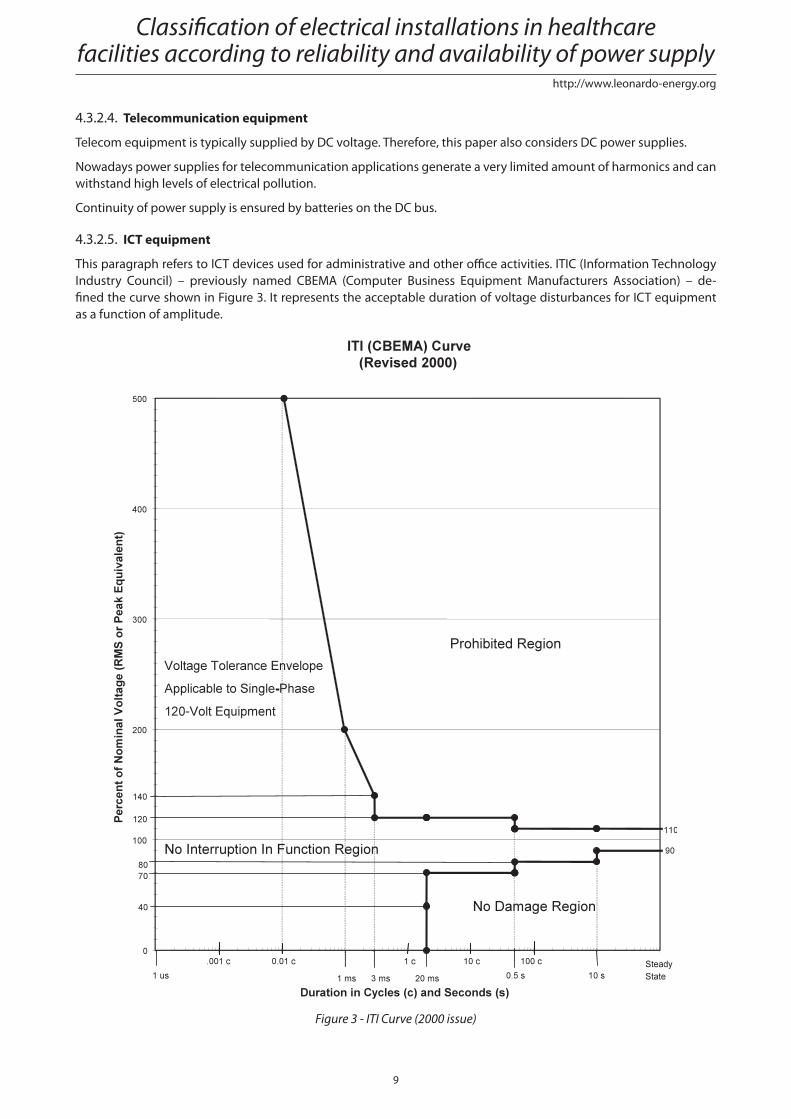
4.3.2.5. ICT equipment
This paragraph refers to ICT devices used for administrative and other offi ce activities. ITIC (Information Technology
Industry Council) – previously named CBEMA (Computer Business Equipment Manufacturers Association) – de-
fi ned the curve shown in Figure 3. It represents the acceptable duration of voltage disturbances for ICT equipment
as a function of amplitude.
Figure 3 - ITI Curve (2000 issue)
Classifi cation of electrical installations in healthcare facilities according to reliability and availability of power supply
10
http://www.leonardo-energy.org
4.3.2.6. Fire alarms and smoke extractors
For proper operation, fi re alarms and smoke extractors need power continuity via the CPSS.
4.3.2.7. Distribution systems for medical gases
Gases are delivered under pressure. The supervision system needs continuity of power supply. An on-line double
conversion UPS is required.
4.3.2.8. Kitchens
For safety of operators, only short interruptions are acceptable. Generator supply is required.
4.3.3. Requirements for Patients’ quality of life
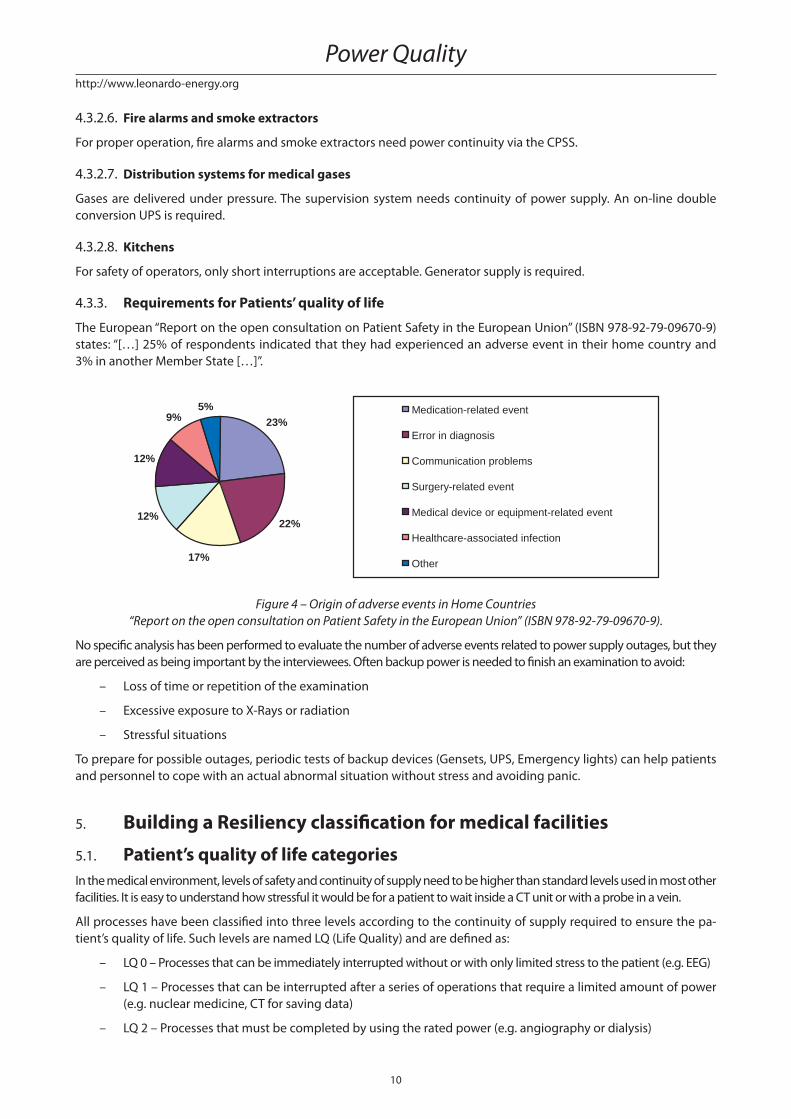
The European “Report on the open consultation on Patient Safety in the European Union” (ISBN 978-92-79-09670-9)
states: “[…] 25% of respondents indicated that they had experienced an adverse event in their home country and
3% in another Member State […]”.
23%
22%
17%
12%
12%
9%5% Medication-related event
Error in diagnosis
Communication problems
Surgery-related event
Medical device or equipment-related event
Healthcare-associated infection
Other
Figure 4 – Origin of adverse events in Home Countries
“Report on the open consultation on Patient Safety in the European Union” (ISBN 978-92-79-09670-9).
No specifi c analysis has been performed to evaluate the number of adverse events related to power supply outages, but they
are perceived as being important by the interviewees. Often backup power is needed to fi nish an examination to avoid:
– Loss of time or repetition of the examination
– Excessive exposure to X-Rays or radiation
– Stressful situations
To prepare for possible outages, periodic tests of backup devices (Gensets, UPS, Emergency lights) can help patients
and personnel to cope with an actual abnormal situation without stress and avoiding panic.
5. Building a Resiliency classifi cation for medical facilities
5.1. Patient’s quality of life categoriesIn the medical environment, levels of safety and continuity of supply need to be higher than standard levels used in most other
facilities. It is easy to understand how stressful it would be for a patient to wait inside a CT unit or with a probe in a vein.
All processes have been classifi ed into three levels according to the continuity of supply required to ensure the pa-
tient’s quality of life. Such levels are named LQ (Life Quality) and are defi ned as:
– LQ 0 – Processes that can be immediately interrupted without or with only limited stress to the patient (e.g. EEG)
– LQ 1 – Processes that can be interrupted after a series of operations that require a limited amount of power
(e.g. nuclear medicine, CT for saving data)
– LQ 2 – Processes that must be completed by using the rated power (e.g. angiography or dialysis)
Power Quality
11
http://www.leonardo-energy.org
In the above mentioned examples, the LQ level may vary depending on the level of service that the hospital or clinic
wants to provide.
It is important to highlight that the LQ levels are related only to the quality of life and not to the risk of death.
The quality of life of the patient is also linked to the knowledge level of nurses and doctors on how to properly use
the medical devices.
For example, some minor incidents have occurred due to improper use of monopolar electro-surgery devices where
there has been incorrect sizing of the passive plate or a lack of consideration of the capacitive coupling between the
patient’s body and the cold mattress. Both cases could have been avoided by a proper training of the operators.
The LQ concept can be also applied to those devices not directly linked to the quality of life of the patients. For
example, ICT devices used for scheduling examinations could also be classifi ed as LQ 2.
5.2. Leonardo ENERGY Healthcare facilities resiliency level identifi cationWith today’s continuous and rapid advancements in medical technology, hospitals, clinics and medical laboratories
increasingly rely on sophisticated electronic devices for the diagnosis, treatment and monitoring of patients. This
reliance, in turn, demands a high level of power quality and reliability. To prevent disruption of mission-critical ser-
vices, equipment should have a low sensitivity to power quality disturbances and should itself generate the minimum
amount of power quality disturbance.
The main problem is a universally accepted defi nition of power quality. In this case, it’s possible to formulate a general one:
“Electrical energy is a product and therefore should meet certain quality requirements. To operate correctly, electri-
cal equipment, requires electrical energy to be supplied at a voltage within a specifi ed range around a rated value.
The user is entitled to receive an acceptable quality of power from the supplier.”
This defi nition cannot, unfortunately, be used in practical terms. Therefore, we need to defi ne power quality benchmarks.
The EN 50160 standard helps by defi ning the voltage parameters of the mains supply and the permissible devia-
tion range at the customer’s point of common coupling in both public low voltage (LV) and medium voltage (MV)
electricity distribution systems, under normal operating conditions. However, no special requirements are defi ned
for specifi c locations such as medical facilities, and the parameter levels are principally informative.
The problem is that consumer’s needs are not always the same. Even fulfi lling the requirements of EN 50160 does
not assure a satisfactory level of power quality (PQ), as this level depends on the application. The level of PQ that
is required must be defi ned in a diff erent way.
For this reason, a classifi cation in terms of the level of resilience of equipment (REL) is introduced:
– REL 0: The equipment (or system) is sensitive to supply voltage disturbances and could be damaged; every
disturbance exceeding EN 50160 levels will aff ect equipment operation. Equipment is damaged by the dis-
turbance and must be replaced or repaired. Downtime period could be very long.
– REL 1: The equipment (or system) is sensitive to supply voltage disturbances with no damage risk. Every
disturbance exceeding EN 50160 levels will aff ect equipment operation. Equipment is not damaged by the
disturbance and downtime is just related to the emergency supply changeover time.
– REL 2: The equipment (or system) is highly resilient. Disturbances exceeding EN 50160 levels will not nec-
essarily aff ect equipment operation. Equipment is not damaged by the disturbance and downtime is just
related to the emergency supply changeover time.
– Table 2 shows the quality of life (LQ) relative to 3 medical location groups as classifi ed by IEC 60364-7-710.
The relationship between the desired LQ level and IEC groups is provided by the resiliency level (REL).
Group (IEC 60364-7-710)
0 1 2
LQ
0 REL 0 REL 1 REL 2
1 REL 1 REL 1 REL 2
2 REL 2 REL 2 REL 2
Table 2 – LE Healthcare facilities Resiliency requirements
Classifi cation of electrical installations in healthcare facilities according to reliability and availability of power supply
12
http://www.leonardo-energy.org
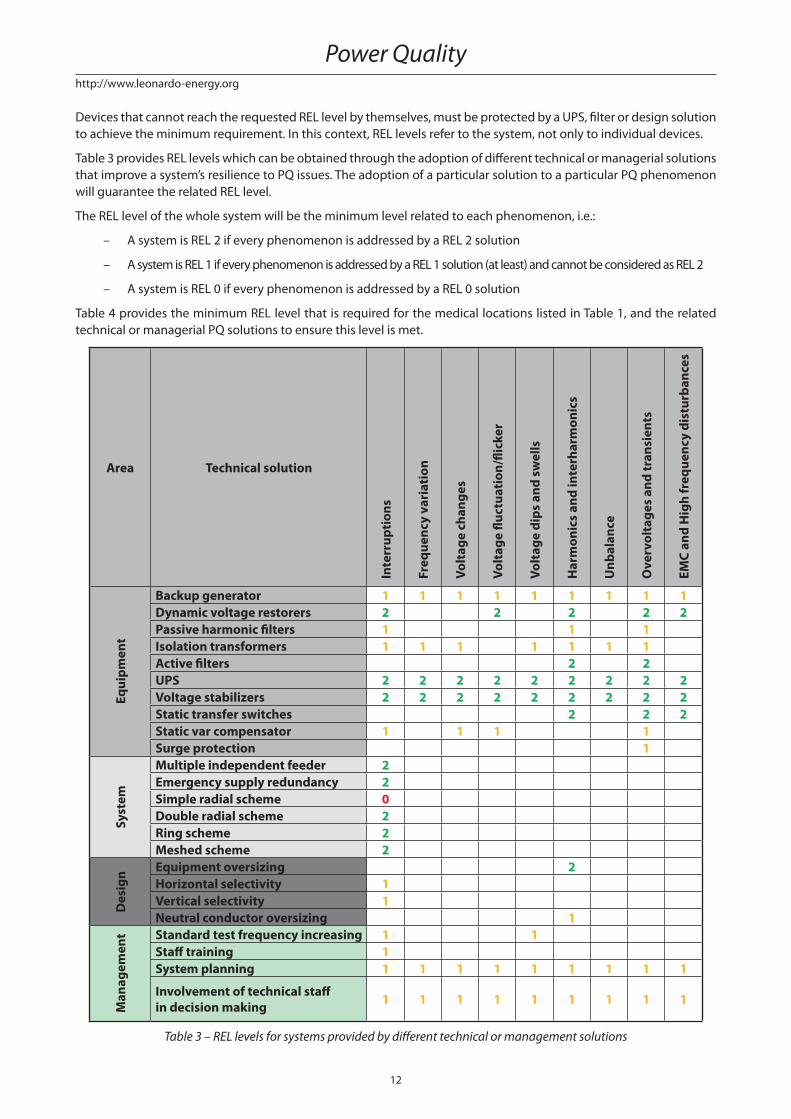
Devices that cannot reach the requested REL level by themselves, must be protected by a UPS, fi lter or design solution
to achieve the minimum requirement. In this context, REL levels refer to the system, not only to individual devices.
Table 3 provides REL levels which can be obtained through the adoption of diff erent technical or managerial solutions
that improve a system’s resilience to PQ issues. The adoption of a particular solution to a particular PQ phenomenon
will guarantee the related REL level.
The REL level of the whole system will be the minimum level related to each phenomenon, i.e.:
– A system is REL 2 if every phenomenon is addressed by a REL 2 solution
– A system is REL 1 if every phenomenon is addressed by a REL 1 solution (at least) and cannot be considered as REL 2
– A system is REL 0 if every phenomenon is addressed by a REL 0 solution
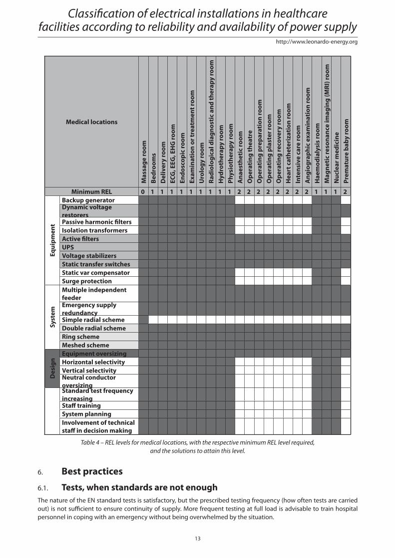
Table 4 provides the minimum REL level that is required for the medical locations listed in Table 1, and the related
technical or managerial PQ solutions to ensure this level is met.
Area Technical solution
Inte
rrup
tion
s
Freq
uenc
y va
riat
ion
Volt
age
chan
ges
Volt
age
fl uct
uati
on/fl
icke
r
Volt
age
dips
and
sw
ells
Har
mon
ics
and
inte
rhar
mon
ics
Unb
alan
ce
Ove
rvol
tage
s an
d tr
ansi
ents
EMC
and
Hig
h fr
eque
ncy
dist
urba
nces
Equi
pmen
t
Backup generator 1 1 1 1 1 1 1 1 1Dynamic voltage restorers 2 2 2 2 2Passive harmonic fi lters 1 1 1Isolation transformers 1 1 1 1 1 1 1Active fi lters 2 2UPS 2 2 2 2 2 2 2 2 2Voltage stabilizers 2 2 2 2 2 2 2 2 2Static transfer switches 2 2 2Static var compensator 1 1 1 1Surge protection 1
Syst
em
Multiple independent feeder 2Emergency supply redundancy 2Simple radial scheme 0Double radial scheme 2Ring scheme 2Meshed scheme 2
Des
ign Equipment oversizing 2
Horizontal selectivity 1Vertical selectivity 1Neutral conductor oversizing 1
Man
agem
ent Standard test frequency increasing 1 1
Staff training 1System planning 1 1 1 1 1 1 1 1 1
Involvement of technical staff in decision making 1 1 1 1 1 1 1 1 1
Table 3 – REL levels for systems provided by diff erent technical or management solutions
Power Quality
13
http://www.leonardo-energy.org
Medical locations
Mas
sage
room
Be
droo
ms
Del
iver
y ro
omEC
G, E
EG, E
HG
room
Endo
scop
ic ro
omEx
amin
atio
n or
trea
tmen
t roo
mU
rolo
gy ro
omRa
diol
ogic
al d
iagn
osti
c an
d th
erap
y ro
omH
ydro
ther
apy
room
Phys
ioth
erap
y ro
omA
naes
thet
ic ro
omO
pera
ting
thea
tre
Ope
rati
ng p
repa
rati
on ro
omO
pera
ting
pla
ster
room
O
pera
ting
reco
very
room
Hea
rt c
athe
teri
zati
on ro
omIn
tens
ive
care
room
Ang
iogr
aphi
c ex
amin
atio
n ro
omH
aem
odia
lysi
s ro
omM
agne
tic
reso
nanc
e im
agin
g (M
RI) r
oom
Nuc
lear
med
icin
ePr
emat
ure
baby
room
Minimum REL 0 1 1 1 1 1 1 1 1 1 2 2 2 2 2 2 2 2 1 1 1 2
Equi
pmen
t
Backup generatorDynamic voltage restorersPassive harmonic fi ltersIsolation transformersActive fi ltersUPSVoltage stabilizersStatic transfer switchesStatic var compensatorSurge protection
Syst
em
Multiple independent feederEmergency supply redundancySimple radial schemeDouble radial schemeRing schemeMeshed scheme
Des
ign
Equipment oversizingHorizontal selectivityVertical selectivityNeutral conductor oversizingStandard test frequency increasingStaff trainingSystem planningInvolvement of technical staff in decision making
Table 4 – REL levels for medical locations, with the respective minimum REL level required,
and the solutions to attain this level.
6. Best practices
6.1. Tests, when standards are not enoughThe nature of the EN standard tests is satisfactory, but the prescribed testing frequency (how often tests are carried
out) is not suffi cient to ensure continuity of supply. More frequent testing at full load is advisable to train hospital
personnel in coping with an emergency without being overwhelmed by the situation.
Classifi cation of electrical installations in healthcare facilities according to reliability and availability of power supply
14
http://www.leonardo-energy.org
All devices connected to the MV/LV transformer must be tested regularly. In particular the following devices require
at least one test per month:
– Circuit Breakers
– Generator set (full load)
– Emergency lights
– CPSS (battery discharge)
6.2. Design Criteria
6.2.1. Neutral conductor systems
In all countries, LV networks and loads are earthed for safety reasons, to avoid the risk of electrocution.
The objectives of earthing are:
– Setting a fi xed voltage potential between live conductors and the earth
– In the event of a failing electrical insulation, limiting the voltage potential between the frames of electrical
equipment and the earth
– Eliminating the risk of individuals receiving an electric shock or being electrocuted
– Limiting voltage surges caused by MV faults
Three earthing systems are standardised internationally: TN (TN-C or TN-S), TT, and IT (including medical IT).
The hospital’s choice of earthing system (how to connect the neutral conductor) depends on the size of the installa-
tion and the IEC standard, and can be summarized as follows:
– In large healthcare facilities, the TN-S system is generally used (except for patient environments in group
2 locations), since the installations are equipped with their own transformer substation
– In small hospitals, the TT system is the most commonly used (except for patient environments in group 2 loca-
tions)
– In all hospitals, patient environments in group 2 locations use the medical IT system
6.2.2. Installation equipment
6.2.2.1. Boards
Boards used in medical IT systems must be equipped with an insulation transformer. If group 2 locations are not com-
pletely fed by a medical IT system and contain ordinary loads, two approaches can be adopted:
– One board feeding both systems (in this case the board must guarantee the separation between the two
systems)
– Two separated boards, one for each system
The choice between these two solutions is made by analysing cost versus system reliability.
6.2.2.2. UPS
This paper focuses on the specifi cs of medical applications. Hence, general requirements are not discussed (emer-
gency power off , cooling, ventilation for batteries, etc.).
EN 62040 defi nes the standard for uninterruptable power supplies (UPS). Part 1-1 of this standard defi nes the “General
and safety requirements for a UPS used in operator access areas”. Part 1-2 defi nes the “General and safety require-
ments for a UPS used in restricted access locations”. Chapter 1.2 states the following: “Even if this standard does not
cover all types of UPS, it may be taken as a guide for such equipment. Requirements additional to those specifi ed
in this standard may be necessary for specifi c applications, for example: […] electro medical applications with the
UPS located within 1.5 m from the patient contact area […]”. This implies the EN 62040-1 standard is suffi cient
for a UPS installed at a minimum of 1.5 m from the patient.
Power Quality
15
http://www.leonardo-energy.org
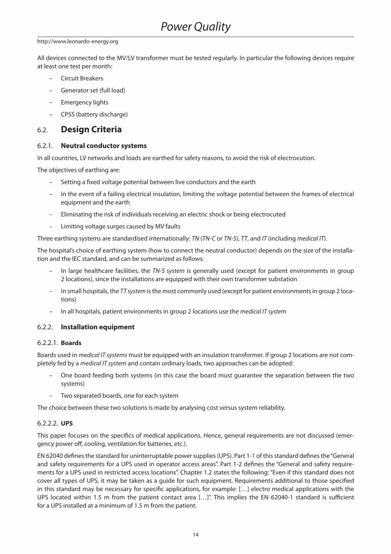
6.2.2.3. X-Ray based devices
A UPS which is designed to supply X-Ray based devices, MRIs or any device with high inrush currents, can diff er
on the following requirements:
- The UPS should supply suffi cient power to get the patient into a safe condition
- The UPS should supply full load until the operation is completed
As already stated in 4.3.1, devices can be sensitive to electrical disturbances, and/or be the source of such distur-
bances. Two major solutions are:
– Properly sizing the local distribution network
– Providing an on-line double conversion (VFI-SS-111) UPS
The latter solution avoids voltage drops due to harmonic currents and electrically separates the mains supply from
loads.
LOAD
Zl
DISTRIBUTIONMAINS
ZgG
Figure 5 - Impedance model of distribution line
LOAD
UPSMAINS
ZgG
Zl
DIST.
Figure 6 – On-line Double Conversion UPS (principle scheme) and distribution line
In cases where only a limited amount of power is required to get the patient into a safe condition, a UPS with lower
power than the rated power of the X-Ray device is typically used to supply the control and measurement systems.
It is important to verify that the device allows for a command to switch in low consumption working mode.
The choice gets more complicated when there is a requirement to complete the examination. Just oversizing the
UPS is not enough, since suffi cient power alone cannot guarantee acceptable dynamic response. The risk of output
voltage distortion remains.
When considering the total cost of ownership (TCO) of the system, a UPS with batteries directly connected to the
DC BUS, or any high input harmonic distortion device (THDI), is not advisable. The reasons are:
– DC voltage ripple reduces battery life
– The upstream plant must be oversized
– It increases the risk of electromagnetic disturbances aff ecting sensitive medical devices
Contact the UPS producer for a proper choice of system.
6.2.2.4. ICT networking devices
Hospitals and clinics include a lot of ICT loads such as servers, workstations and networking switches – to store data,
manage bookings and allow information access. Their sensitivity to electrical disturbances is lower than that of medi-
cal devices, as shown in Figure 3.
Classifi cation of electrical installations in healthcare facilities according to reliability and availability of power supply
16
http://www.leonardo-energy.org
Despite the fact that the ITI curve allows supply interruptions up to 20 ms, it is advisable to foresee an on-line double
conversion UPS to protect ICT devices from harmonics and overvoltages.
Especially for computer servers, it is recommended to select a UPS with the following characteristics:
– A unitary input power factor to avoid the need for upstream oversizing
– A leading output power factor of 0.9 to ensure the highest power density
– A high effi ciency across a wide range of loads, to ensure energy saving and minimum carbon footprint at low
load (typical for data centres)
6.2.2.5. Central Power Supply System
A Central Power Supply System (CPSS) is a UPS matching the requirements of both EN 62040 and EN 50171 standards.
The main requirements of the latter are:
– Use of long life batteries
– Protection against battery polarity inversion
– Dry contact signalling
– A battery charger protected against short circuits
– 80% of battery recharge in 12 hours
– Fire resistance
Additional requirements can be stipulated by national laws.
A CPSS must be used to feed emergency lights, fi re alarms, smoke extractors and all electrical systems related to safety.
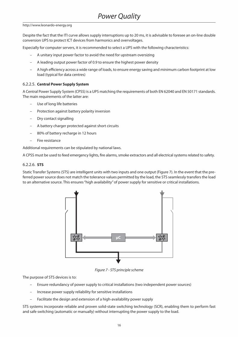
6.2.2.6. STS
Static Transfer Systems (STS) are intelligent units with two inputs and one output (Figure 7). In the event that the pre-
ferred power source does not match the tolerance values permitted by the load, the STS seamlessly transfers the load
to an alternative source. This ensures “high availability” of power supply for sensitive or critical installations.
μC
Figure 7 - STS principle scheme
The purpose of STS devices is to:
– Ensure redundancy of power supply to critical installations (two independent power sources)
– Increase power supply reliability for sensitive installations
– Facilitate the design and extension of a high-availability power supply
STS systems incorporate reliable and proven solid-state switching technology (SCR), enabling them to perform fast
and safe switching (automatic or manually) without interrupting the power supply to the load.
Power Quality
17
http://www.leonardo-energy.org
IEEE publication Std 493-2007, Design of Reliable Industrial and Commercial Power System, analyses the mutual
influence of dual-cord loads in a 2N supply architecture in terms of availability. Because it electrically separates
loads, the STS can be used to avoid failure propagation, preventing any mutual influences. This again improves
availability.
2N architecture Inherent Availability Probability of failure (5 years)12 dual-cord loads 0.9999913 16.61%
24 dual cord loads 0.9999825 31.13%
Table 5 - Mutual infl uence of loads
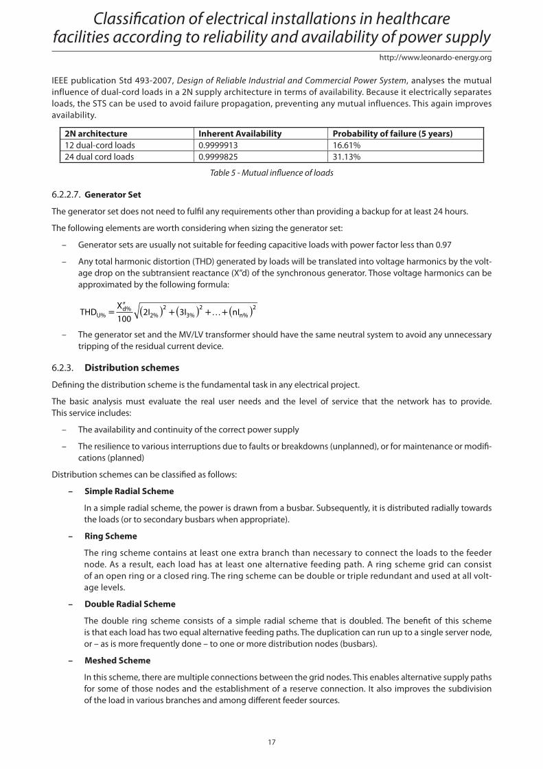
6.2.2.7. Generator Set
The generator set does not need to fulfi l any requirements other than providing a backup for at least 24 hours.
The following elements are worth considering when sizing the generator set:
– Generator sets are usually not suitable for feeding capacitive loads with power factor less than 0.97
– Any total harmonic distortion (THD) generated by loads will be translated into voltage harmonics by the volt-
age drop on the subtransient reactance (X”d) of the synchronous generator. Those voltage harmonics can be
approximated by the following formula:
THDX
1002I 3I nIU%
d%2%
2
3%
2
n%
2=
′′ ( ) +( ) + +( )…
– The generator set and the MV/LV transformer should have the same neutral system to avoid any unnecessary
tripping of the residual current device.
6.2.3. Distribution schemes
Defi ning the distribution scheme is the fundamental task in any electrical project.
The basic analysis must evaluate the real user needs and the level of service that the network has to provide.
This service includes:
– The availability and continuity of the correct power supply
– The resilience to various interruptions due to faults or breakdowns (unplanned), or for maintenance or modifi -
cations (planned)
Distribution schemes can be classifi ed as follows:
– Simple Radial Scheme
In a simple radial scheme, the power is drawn from a busbar. Subsequently, it is distributed radially towards
the loads (or to secondary busbars when appropriate).
– Ring Scheme
The ring scheme contains at least one extra branch than necessary to connect the loads to the feeder
node. As a result, each load has at least one alternative feeding path. A ring scheme grid can consist
of an open ring or a closed ring. The ring scheme can be double or triple redundant and used at all volt-
age levels.
– Double Radial Scheme
The double ring scheme consists of a simple radial scheme that is doubled. The benefi t of this scheme
is that each load has two equal alternative feeding paths. The duplication can run up to a single server node,
or – as is more frequently done – to one or more distribution nodes (busbars).
– Meshed Scheme
In this scheme, there are multiple connections between the grid nodes. This enables alternative supply paths
for some of those nodes and the establishment of a reserve connection. It also improves the subdivision
of the load in various branches and among diff erent feeder sources.
Classifi cation of electrical installations in healthcare facilities according to reliability and availability of power supply
18
http://www.leonardo-energy.org
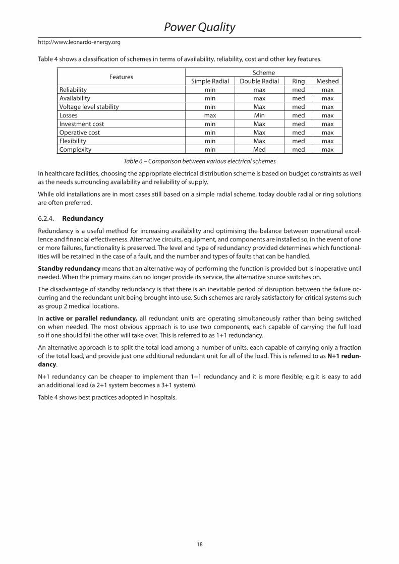
Table 4 shows a classifi cation of schemes in terms of availability, reliability, cost and other key features.
FeaturesScheme
Simple Radial Double Radial Ring Meshed
Reliability min max med max
Availability min max med max
Voltage level stability min Max med max
Losses max Min med max
Investment cost min Max med max
Operative cost min Max med max
Flexibility min Max med max
Complexity min Med med max
Table 6 – Comparison between various electrical schemes
In healthcare facilities, choosing the appropriate electrical distribution scheme is based on budget constraints as well
as the needs surrounding availability and reliability of supply.
While old installations are in most cases still based on a simple radial scheme, today double radial or ring solutions
are often preferred.
6.2.4. Redundancy
Redundancy is a useful method for increasing availability and optimising the balance between operational excel-
lence and fi nancial eff ectiveness. Alternative circuits, equipment, and components are installed so, in the event of one
or more failures, functionality is preserved. The level and type of redundancy provided determines which functional-
ities will be retained in the case of a fault, and the number and types of faults that can be handled.
Standby redundancy means that an alternative way of performing the function is provided but is inoperative until
needed. When the primary mains can no longer provide its service, the alternative source switches on.
The disadvantage of standby redundancy is that there is an inevitable period of disruption between the failure oc-
curring and the redundant unit being brought into use. Such schemes are rarely satisfactory for critical systems such
as group 2 medical locations.
In active or parallel redundancy, all redundant units are operating simultaneously rather than being switched
on when needed. The most obvious approach is to use two components, each capable of carrying the full load
so if one should fail the other will take over. This is referred to as 1+1 redundancy.
An alternative approach is to split the total load among a number of units, each capable of carrying only a fraction
of the total load, and provide just one additional redundant unit for all of the load. This is referred to as N+1 redun-dancy.
N+1 redundancy can be cheaper to implement than 1+1 redundancy and it is more fl exible; e.g.it is easy to add
an additional load (a 2+1 system becomes a 3+1 system).
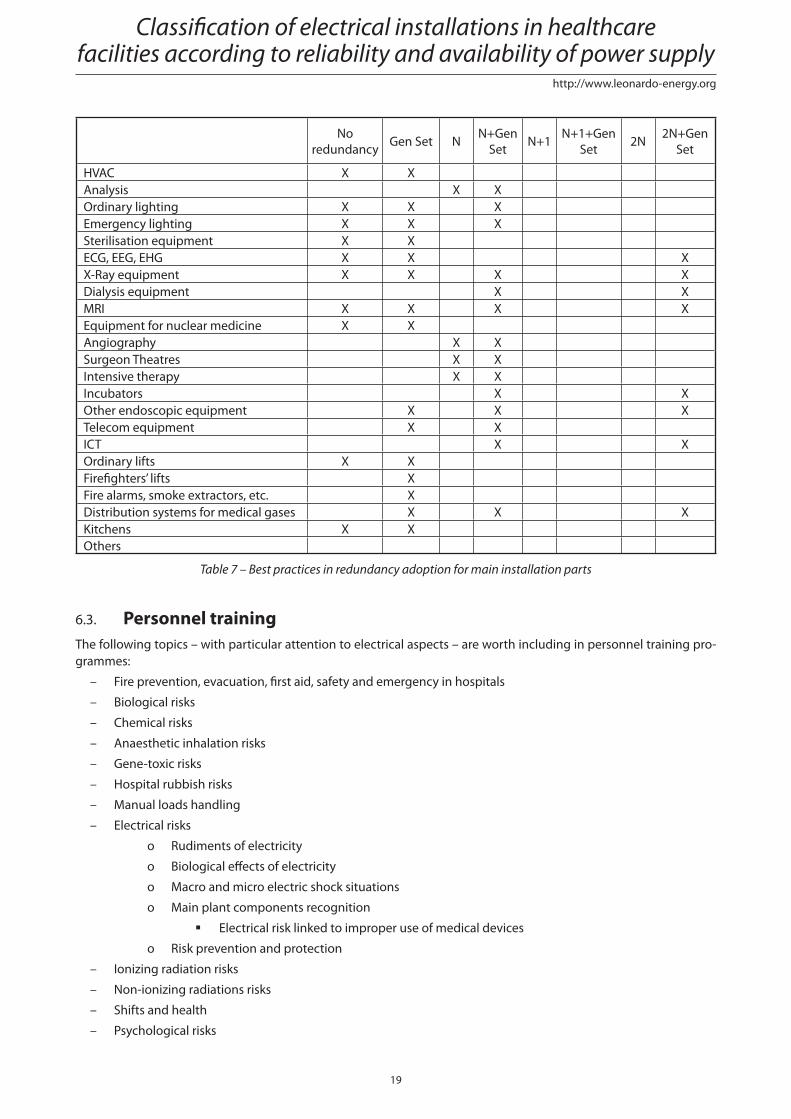
Table 4 shows best practices adopted in hospitals.
Power Quality
19
http://www.leonardo-energy.org
No
redundancyGen Set N
N+Gen
SetN+1
N+1+Gen
Set2N
2N+Gen
Set
HVAC X X
Analysis X X
Ordinary lighting X X X
Emergency lighting X X X
Sterilisation equipment X X
ECG, EEG, EHG X X X
X-Ray equipment X X X X
Dialysis equipment X X
MRI X X X X
Equipment for nuclear medicine X X
Angiography X X
Surgeon Theatres X X
Intensive therapy X X
Incubators X X
Other endoscopic equipment X X X
Telecom equipment X X
ICT X X
Ordinary lifts X X
Firefi ghters’ lifts X
Fire alarms, smoke extractors, etc. X
Distribution systems for medical gases X X X
Kitchens X X
Others
Table 7 – Best practices in redundancy adoption for main installation parts
6.3. Personnel trainingThe following topics – with particular attention to electrical aspects – are worth including in personnel training pro-
grammes:
– Fire prevention, evacuation, fi rst aid, safety and emergency in hospitals
– Biological risks
– Chemical risks
– Anaesthetic inhalation risks
– Gene-toxic risks
– Hospital rubbish risks
– Manual loads handling
– Electrical risks
o Rudiments of electricity
o Biological eff ects of electricity
o Macro and micro electric shock situations
o Main plant components recognition
Electrical risk linked to improper use of medical devices
o Risk prevention and protection
– Ionizing radiation risks
– Non-ionizing radiations risks
– Shifts and health
– Psychological risks
Classifi cation of electrical installations in healthcare facilities according to reliability and availability of power supply
20
http://www.leonardo-energy.org
– VDU risks
– Personal protection devices
– Safety signals
7. ConclusionsThe IEC standard for electrical installations in medical locations focus on safety aspects, in particular the protection
against indirect contact. Its requirements in terms of availability of supply and overall reliability are qualitative rather
than quantitative.
There is a serious need for a universally accepted defi nition of availability and reliability levels of power supplies.
The quality of healthcare applications relies on suffi cient availability of the power supply and the adequate performance
of the electrical installation. This was the conclusion from several interviews with medical staff and technicians.
The interviews also highlighted another strong need: to introduce more severe directives for the frequency of pe-
riodic testing. The current standards are considered (almost unanimously) to be insuffi cient to guarantee safety, re-
liability and availability of emergency supply systems. Almost every interviewed technician proposed to increase
the frequency of periodic testing to at least twice that currently prescribed by IEC 60364-7-710.
The IEC standard classifi es medical locations as group 0, group 1 or group 2 according to the use of applied parts and
whether the patient’s life is at risk or not.
Two innovative notions were introduced in this paper: the resilience of equipment to power quality disturbances (REL)
and the patient’s quality of life (LQ). Based on these notions, a new classifi cation scheme for the resilience level of health-
care facilities was built up. This scheme does not merely consider the safety of the patient, but also takes into account:
– The availability, resilience and reliability of the power supply
– The patient’s quality of life
It enables decision makers and technical staff of healthcare facilities to properly design the electrical installation
for the best quality of life for patients, using the most cost eff ective technical solution, and do so in accordance with
the IEC 60364-7-710 classifi cation scheme.
8. References[1] IEC 60364-7-710: Electrical installations of buildings - Part 7-710: Requirements for special installations or loca-
tions - Medical locations.
[2] EN 50160: Voltage characteristics of electricity supplied by public distribution systems, 1999.
[3] Angelo Baggini: Handbook of Power Quality. John Wiley & Sons, Ltd. Chichester 2008.
[4] Jonathan Manson, Roman Targosz: European Power Quality Survey Report – Leonardo Energy (www.leonardo–
energy.org)
[5] Philip Keebler: Power Quality for Healthcare Facilities. EPRI Techwatch, December 2007
[6] David Chapman: Introduction to Power Quality. Leonardo Energy Application Guide, November 2001.
[7] Gary Marshall, David Chapman: Resilience, Reliability and Redundancy. Leonardo Energy Application Guide, May 2002.
[8] Emiliano Cevenini: UPS Architectures for Power Quality improvement.
[9] A. Sudrià, E. Jaureguialzo, A. Sumper, R. Villafáfi la and J. Rull: High Power UPS Selection Methodology and
Installation Guideline for High Reliability Power Supply.
[10] Brian Fortenbury: High Performance Buildings: Data Centers - Uninterruptible Power Supplies (UPS).
Power Quality

![Bergamo 2013 [modalità compatibilità] · Spigolo Bordo Centro Sotto pila Termine costruzione 1.30 1.00 0.80 0.90 3 anni dopo t.c. 1.16 0.96 0.90 0.98 10 anni dopo t.c. 1.10 0.93](https://static.fdocument.org/doc/165x107/5c6590e009d3f2a86e8ccb99/bergamo-2013-modalita-compatibilita-spigolo-bordo-centro-sotto-pila-termine.jpg)