ANFCA-4545-A01 Pb RoHS/RoHS II compliant · ANFCA-4545-A01 Figure (2) – Matching Circuit...
3
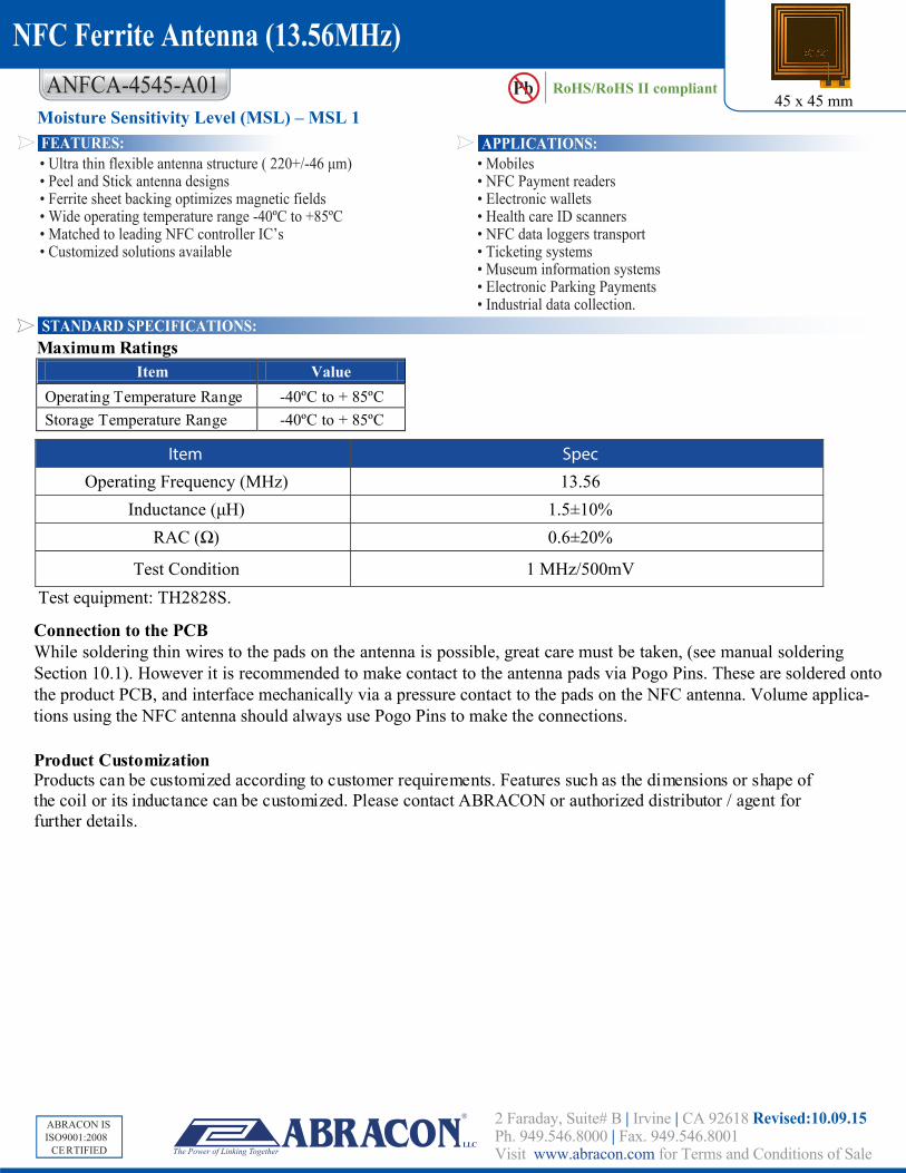
ANFCA-4545-A01 • Mobiles • NFC Payment readers • Electronic wallets • Health care ID scanners • NFC data loggers transport • Ticketing systems • Museum information systems • Electronic Parking Payments • Industrial data collection. • Ultra thin flexible antenna structure ( 220+/-46 μm) • Peel and Stick antenna designs • Ferrite sheet backing optimizes magnetic fields • Wide operating temperature range -40ºC to +85ºC • Matched to leading NFC controller IC’s • Customized solutions available APPLICATIONS: FEATURES: STANDARD SPECIFICATIONS: ABRACON IS CE RTIFIED ABRACON IS ISO9001:2008 CE RTIFIED Moisture Sensitivity Level (MSL) – MSL 1 45 x 45 mm Pb RoHS/RoHS II compliant NFC Ferrite Antenna (13.56MHz) Maximum Ratings Item Value Operating Temperature Range -40ºC to + 85ºC Storage Temperature Range -40ºC to + 85ºC 2 Faraday, Suite# B | Irvine | CA 92618 Revised:10.09.15 Ph. 949.546.8000 | Fax. 949.546.8001 Visit www.abracon.com for Terms and Conditions of Sale LLC Item Spec 6 5 . 3 1 ) z H M ( y c n e u q e r F g n i t a r e p O Inductance (μ % 0 1 ± 5 . 1 ) H RAC (Ω % 0 2 ± 6 . 0 ) V m 0 0 5 / z H M 1 n o i t i d n o C t s e T Test equipment: TH2828S. Product Customization Products can be customized according to customer requirements. Features such as the dimensions or shape of the coil or its inductance can be customized. Please contact ABRACON or authorized distributor / agent for further details. Connection to the PCB While soldering thin wires to the pads on the antenna is possible, great care must be taken, (see manual soldering Section 10.1). However it is recommended to make contact to the antenna pads via Pogo Pins. These are soldered onto the product PCB, and interface mechanically via a pressure contact to the pads on the NFC antenna. Volume applica- tions using the NFC antenna should always use Pogo Pins to make the connections.
Transcript of ANFCA-4545-A01 Pb RoHS/RoHS II compliant · ANFCA-4545-A01 Figure (2) – Matching Circuit...
ANFCA-4545-A01
• Mobiles• NFC Payment readers• Electronic wallets• Health care ID scanners• NFC data loggers transport • Ticketing systems• Museum information systems• Electronic Parking Payments• Industrial data collection.
• Ultra thin flexible antenna structure ( 220+/-46 μm)• Peel and Stick antenna designs• Ferrite sheet backing optimizes magnetic fields• Wide operating temperature range -40ºC to +85ºC• Matched to leading NFC controller IC’s• Customized solutions available
APPLICATIONS:FEATURES:
STANDARD SPECIFICATIONS:
ABRACON IS
CERTIFIED
ABRACON IS ISO9001:2008
CERTIFIED
Moisture Sensitivity Level (MSL) – MSL 145 x 45 mm
Pb RoHS/RoHS II compliant
NFC Ferrite Antenna (13.56MHz)
Maximum Ratings
Item Value Operating Temperature Range -40ºC to + 85ºC Storage Temperature Range -40ºC to + 85ºC
2 Faraday, Suite# B | Irvine | CA 92618 Revised:10.09.15Ph. 949.546.8000 | Fax. 949.546.8001 Visit www.abracon.com for Terms and Conditions of Sale
LLC
Item Spec
65.31 )zHM( ycneuqerF gnitarepOInductance (μ %01±5.1 )H
RAC (Ω %02±6.0 )
Vm005/zHM 1 noitidnoC tseT Test equipment: TH2828S.
Product CustomizationProducts can be customized according to customer requirements. Features such as the dimensions or shape of the coil or its inductance can be customized. Please contact ABRACON or authorized distributor / agent for further details.
Connection to the PCB While soldering thin wires to the pads on the antenna is possible, great care must be taken, (see manual soldering Section 10.1). However it is recommended to make contact to the antenna pads via Pogo Pins. These are soldered onto the product PCB, and interface mechanically via a pressure contact to the pads on the NFC antenna. Volume applica-tions using the NFC antenna should always use Pogo Pins to make the connections.
ANFCA-4545-A01
ABRACON IS
CERTIFIED
ABRACON IS ISO9001:2008
CERTIFIED
45 x 45 mmPb RoHS/RoHS II compliant
NFC Ferrite Antenna (13.56MHz)
2 Faraday, Suite# B | Irvine | CA 92618 Revised:10.09.15Ph. 949.546.8000 | Fax. 949.546.8001 Visit www.abracon.com for Terms and Conditions of Sale
LLC
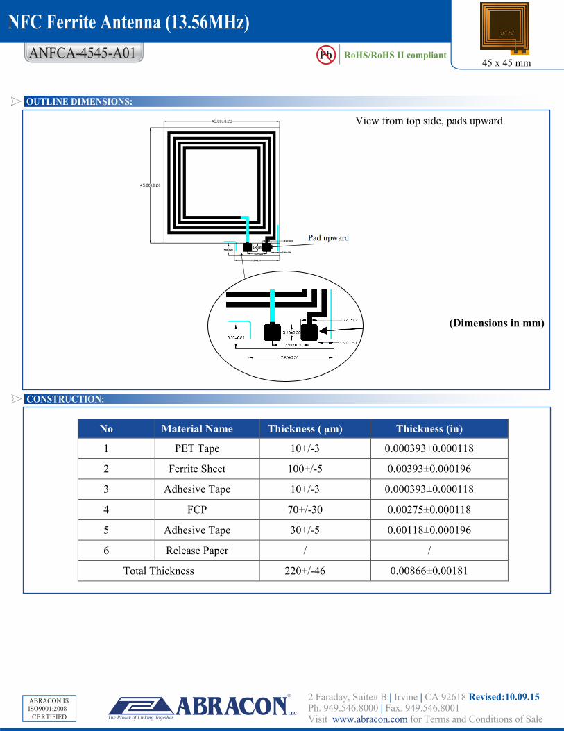
OUTLINE DIMENSIONS:
No Material Name Thickness ( μm) Thickness (in)
1 PET Tape 10+/-3 0.000393±0.000118
2 Ferrite Sheet 100+/-5 0.00393±0.000196
3 Adhesive Tape 10+/-3 0.000393±0.000118
4 FCP 70+/-30 0.00275±0.000118
5 Adhesive Tape 30+/-5 0.00118±0.000196
6 Release Paper / /
Total Thickness 220+/-46 0.00866±0.00181
CONSTRUCTION:
(Dimensions in mm)
View from top side, pads upward
ABRACON IS
CERTIFIED
ABRACON IS ISO9001:2008
CERTIFIED
45 x 45 mmPb RoHS/RoHS II compliant
NFC Ferrite Antenna (13.56MHz)
MATCHING CIRCUIT AND REFERENCE VALUES
Reflow Profile: Not recommended for reflow soldering
Manual Soldering: Recommended Soldering iron temperature setting: 330°C, 3 seconds max, 3 times max.
Packaging: 100pcs per polyphene bag / box
ATTENTION: Abracon Corporation’s products are COTS – Commercial-Off-The-Shelf products; suitable for Commercial, Industrial and, where designated, Automotive Applica-tions. Abracon’s products are not specifically designed for Military, Aviation, Aerospace, Life-dependant Medical applications or any application requiring high reliability where component failure could result in loss of life and/or property. For applications requiring high reliability and/or presenting an extreme operating environment, written consent and authorization from Abracon Corporation is required. Please contact Abracon Corporation for more information.
ANFCA-4545-A01
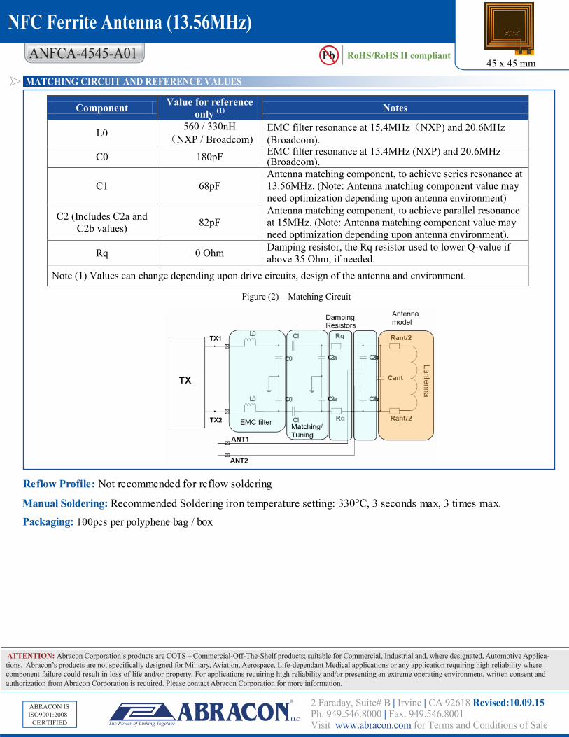
Figure (2) – Matching Circuit
Component Value for reference only (1) Notes
L0 560 / 330nH (NXP / Broadcom)
EMC filter resonance at 15.4MHz(NXP) and 20.6MHz (Broadcom).
C0 180pF EMC filter resonance at 15.4MHz (NXP) and 20.6MHz (Broadcom).
C1 68pF Antenna matching component, to achieve series resonance at 13.56MHz. (Note: Antenna matching component value may need optimization depending upon antenna environment)
C2 (Includes C2a and C2b values) 82pF
Antenna matching component, to achieve parallel resonance at 15MHz. (Note: Antenna matching component value may need optimization depending upon antenna environment).
Rq 0 Ohm Damping resistor, the Rq resistor used to lower Q-value if above 35 Ohm, if needed.
Note (1) Values can change depending upon drive circuits, design of the antenna and environment.
2 Faraday, Suite# B | Irvine | CA 92618 Revised:10.09.15Ph. 949.546.8000 | Fax. 949.546.8001 Visit www.abracon.com for Terms and Conditions of Sale
LLC