ampcontrol’s - Whitepages€¦ · All of the protection functions are combined into a compact,...
24
ampcontrol’s Hard rock relay range
Transcript of ampcontrol’s - Whitepages€¦ · All of the protection functions are combined into a compact,...
ampcontrol’sHard rock relay range

TABLE OF CONTENTS
Introduction 1
Earth fault lockout andfrozen contactor protection
∙ EFL 3
Integrated protection
∙ PF1 5
∙ IPM V2 7
Earth continuity
∙ MEC-1 9
∙ ECM2 11
Earth leakage
∙ ELM 13
∙ ELD V2 15
Wide bandwidth earth leakage
∙ ELV 17
∙ VSDguard 19

1 ampcontrolgroup.com | 1300 267 373 | V2 May 2016
Ampcontrol is at the forefront of electrical protection with over 40 years experience in the design and manufacture of protection and monitoring control relays.
In an industry where safety is paramount, Ampcontrol has a proven track record of delivering products to suit the unique system challenges and hazards of hard rock mining applications.
Our comprehensive and cost effective range of relays ensure safe and stable electrical systems and provide:
• Increased personnel protection and safety
• Continuous monitoring of electrical system integrity allowing early removal of hazardous situations
• Increased plant protection and improved economic efficiency
• Reduced downtime and fault damage
• Accurate measurements negating nuisance tripping
• Event logging assisting integration of past faults
• Detection of potential fire hazards caused by high fault currents
• AS/NZS2081 compliance
Ampcontrol’s hard rock range of relays includes protection solutions for all applications through integrated and individual relay protection for earth leakage, earth continuity, earth fault lockout and frozen contactor.
Leaders in electrical protection and safety
ampcontrolgroup.com | © Ampcontrol 2
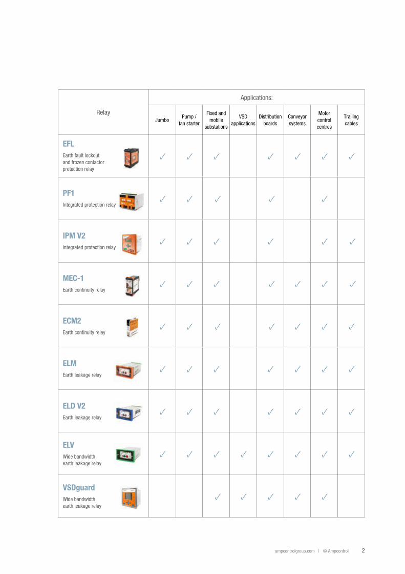
Relay
Applications:
JumboPump /
fan starter
Fixed andmobile
substations
VSDapplications
Distributionboards
Conveyorsystems
Motorcontrolcentres
Trailingcables
EFLEarth fault lockoutand frozen contactorprotection relay
PF1Integrated protection relay
IPM V2Integrated protection relay
MEC-1Earth continuity relay
ECM2Earth continuity relay
ELMEarth leakage relay
ELD V2Earth leakage relay
ELVWide bandwidthearth leakage relay
VSDguardWide bandwidthearth leakage relay
3 ampcontrolgroup.com | 1300 267 373 | V2 May 2016
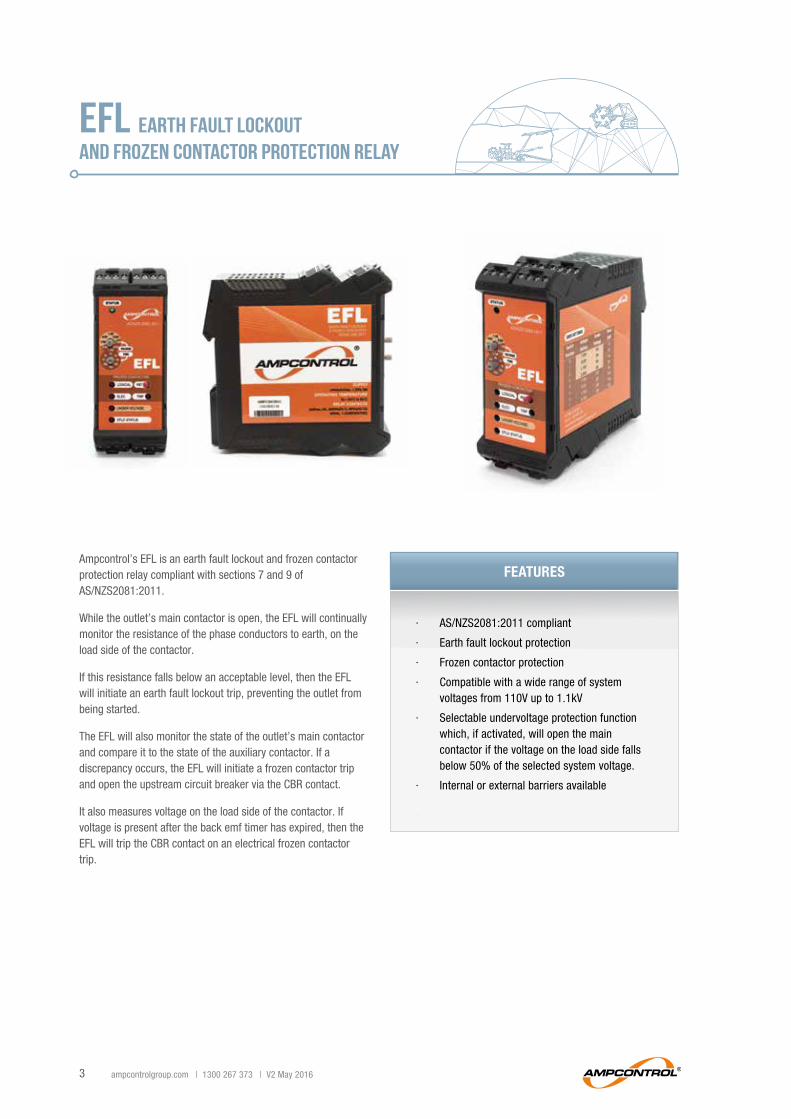
EFL Earth fault lockoutand frozen contactor protection relay
∙ AS/NZS2081:2011 compliant
∙ Earth fault lockout protection
∙ Frozen contactor protection
∙ Compatible with a wide range of system voltages from 110V up to 1.1kV
∙ Selectable undervoltage protection function which, if activated, will open the main contactor if the voltage on the load side falls below 50% of the selected system voltage.
∙ Internal or external barriers available
∙
Ampcontrol’s EFL is an earth fault lockout and frozen contactor protection relay compliant with sections 7 and 9 of AS/NZS2081:2011.
While the outlet’s main contactor is open, the EFL will continually monitor the resistance of the phase conductors to earth, on the load side of the contactor.
If this resistance falls below an acceptable level, then the EFL will initiate an earth fault lockout trip, preventing the outlet from being started.
The EFL will also monitor the state of the outlet’s main contactor and compare it to the state of the auxiliary contactor. If a discrepancy occurs, the EFL will initiate a frozen contactor trip and open the upstream circuit breaker via the CBR contact.
It also measures voltage on the load side of the contactor. If voltage is present after the back emf timer has expired, then the EFL will trip the CBR contact on an electrical frozen contactor trip.
FEaturES
ampcontrolgroup.com | © Ampcontrol 4
SpEcIfIcatIonS
power Supply
Voltage24Vdc ± 20% or,24Vac ± 20%, 50Hz
Power consumption < 5W
outputs
Relay contacts 2 x CO (NC-COM-NC)2 x NC
Rating 250VAC, 6A, 300VA (AC1), 60VA (AC15), 30VDC, 1.2A (DC1)
Mechanical and Environment
Dimensions (HxWxD)111 x 45 x 114 mm (EFL)111 x 22 x 114 mm (barrier)111 x 75 x 114 mm (EFL with internal barrier)
Ingress protection IP20
Operating temperature -20°C to 60°C
Humidity Between 10% relative humidity and the dew point, non-condensing
Air flow The EFL is to be mounted in a position that allows unrestricted air flow through the upper and lower air vents
System
Outlet voltage 110V, 415V, 1.1kV (selectable)
paRt nUMBER DEScRIptIon
173151 EFL Protection Relay
173175 EFL Protection Relay with Internal 415V-1100V Barrier
173176 External 110V-1100V Barrier suit EFL Protection Relay

5 ampcontrolgroup.com | 1300 267 373 | V2 May 2016
PF1INTEGRATED PROTECTION relay
∙ AS/NZS2081:2011 compliant
∙ 24VAC or 24VDC operation
∙ Selectable remote start/stop functionality
∙ LED status indication to aid in fault finding
∙ Event data logging
∙ Configurable parameters through USB connection to PC running Smart Tools Software
∙ Selectable pump protection mode (snore) can assist in maintaining optimum motor efficiency by detecting load decreases
∙ Selectable fan protection mode (burp) can prevent damage to the material of the ventilation tube during the initial stages of inflation
Ampcontrol’s PF1 Pump and Fan relay is an integrated protection relay which performs two standard protection functions and is compliant to AS/NZS2081:2011 – earth leakage and earth continuity.
The PF1 provides selectable control functionality for fan or pump motor installations. When applied correctly, these modes significantly reduce the risk of damage to equipment and also considerably reduce maintenance requirements.
Pump protection mode manages the no-load/undercurrent condition of a pump by monitoring the load current. When the load on the pump motor decreases the speed of the pump motor will rise to its maximum, which can burn out the pump motor.
Fan protection mode manages the gradual pre-inflation of flexible ventilation conduit, by applying a pulsed (burp) start-up sequence to the fan motor.
Both functions can be deactivated.
FEaturES
ampcontrolgroup.com | © Ampcontrol 6
paRt nUMBER DEScRIptIon
174403
PF1 Pump & Fan relay kit(including relay, current transformer, earth leakage toroid, 100Ω remote start resistor, earth continuity terminating diode, USB drive containing user manual, technical datasheet and Smart Tools software and USB cable)
SpEcIfIcatIonS
power Supply
Voltage18 to 28.8VDC or,18 to 28.8VAC to 60Hz
Power consumption <15VA
Relay contacts
Rating 110VAC/30VDC 1A (resistive)
Earth Leakage
CT ratio 100:1
Toroid output power (max) 15VA
Primary input current 30 – 1100mA (nominal)
PassbandWide band mode: 30 – 500Hz (±3%)50Hz mode: 30 – 90Hz (±3%)
Trip times 50 to 500ms
Trip levels 30 to 1000mA
Earth continuity
Trip times 50 to 500ms
Trip levels 10 to 45Ω
Terminating diode 1N5404 3A
pump and fan
Primary input current 1 to 200A
Mechanical and Environment
Dimensions (HxWxD)With plugs: 100 x 105 x 110 mmWithout plugs: 100 x 85 x 110 mm
Operating temperature range -10 to 60˚C
Storage temperature range -20 to 70˚C
Humidity Between 10% relative humidity and the dew point, non-condensing

7 ampcontrolgroup.com | 1300 267 373 | V2 May 2016
IPM V2integrated protection RELAY
Ampcontrol’s IPM V2 is an intelligent microprocessor based protection relay.
The IPM V2 relay provides all the functions required for protecting electrical outlets supplying underground mining machinery, powered by reeling or trailing cables. The relay can also be used to provide optimum overload protection of motors used on conveyors, pumps, fans and compressors.
Additionally the IPM2 V2 provides pump (snore) and fan (burp) control to protect pump and fan motors.
All of the protection functions are combined into a compact, plug-in unit, which can be easily changed to minimise downtime in the event of a problem with the relay.
Machine data transfer is provided through the use of a Remote Termination Module (RTM) which allows the relay parameters to be automatically uploaded from the machine when a cable is inserted into a power outlet. The RTM also allows for remote start capability.
An automatic insulation test ensures the resistance of the cable insulation to earth exceeds the selected value before allowing the main contactor to close. This is coupled with a manual insulation test to allow fault finding.
∙ Integrated protection functionality with pump and fan control
∙ Machine recognition using Remote Termination Module (RTM)
∙ RS485 communication port interfaces to SCADA system via Modbus protocol to provide continuous monitoring and fault finding
∙ 4-20mA analogue output allows continuous monitoring of the current, voltage, earth leakage and insulation levels
∙ Battery backed 50 event log with real time clock and 20 character backlit LCD display and keypad for ease of use
∙ Relay and digital input status to aid fault finding
∙ Local or remote operation including remote start capability
∙ Compact, plug-in unit which can be easily changed out to minimise downtime
∙
FEaturES
ampcontrolgroup.com | © Ampcontrol 8
SpEcIfIcatIonS
power Supply
Voltage 24VAC / DC ± 20%
Power consumption <10W
protection Settings
Earth leakage protectionTrip setting 25-500mA and off
Time delay – instantaneous (<80ms), 50ms - 150ms
Earth continuity protection
Reset if resistance is <45Ω
Trip if resistance is > 45Ω
Trip time delay: 80, 120, 160, 200, 300, 400, 500ms
Shunt leakage trip if <1500Ω
Overload protection
Current range: 0.5 to 640 (224 steps) – CT dependent
Trip time @ 6x FLC: 3, 4, 5, 6, 7, 8, 10, 12, 14, 16, 20, 24, 28, 32, 40s
Overload reset level: 30%, 40%, 50%, 60%, 70%, 80%, 90%, A-30%, A-40%, A-50%, A-60%, A-70%, A-80%, A-90%
Cooling multiplier 1, 1.5, 2, 2.5, 3, 4, 5
Short circuit protectionTrip setting: 3 to 10 times in 0.5 increments (times full load)
Trip time: 20, 40, 60, 80, 100, 120, 160ms
Under voltage protectionSelectable from 20% to 80% in 10% increments
Trip delay: 800ms
Under current protectionSelectable from 32% to 96% in 8% increments and none
Trip delay: 800ms
Insulation test Lockout resistance is selectable at 1, 2, 5, 10, 20 MΩ and none
Current balanceTrip settings: 5%, 10%, 20%, 50% and off
Trip delay: 2s
Residual currentTrip setting: 10% to 250% and off
Trip time: 100ms to 5s
Back EMF timer Trip delay settings: 2, 5, 10, 15 and 20s
Machine numbers Can be allocated from 1 to 40
Burp functionNo pulses setting: 1 to 6 any none
Time on/time off setting: 0.6, 0.8, 1.0, 1.2, 1.5, 2.0, 2.5 and 3.0s
Snore function None, 5, 10,15, 20, 8F, 15F, 20F, 30F, 60F (Time in minutes F= fixed delay)
outputs
CommunicationsRS485 Slave MODBUS
Baud rate: 1200 to 19200
Monitoring 4-20mA Analogue output – lave, O/L, E/L, MΩ
Relay contactsMCR (1 NO, 1 C/O), CBR and ALM (1 C/O)
5A/190VAC 100VA max
Mechanical and Environment
Dimensions (HxWxD) 155 x 155 x 130 mm
Ingress protection IP56 (when panel mounted)
paRt nUMBER DEScRIptIon
143794 IPM Integrated Protection Relay 24V
121504 ITM-415 Insulation Test Module
121505 ITM-1000V Insulation Test Module
143315 RTM Remote Termination Module
101703 88mm Earth leakage Toroid
141548 Current Transformer 100:1 [500:5]
101272 Current Transformer 1000:1
9 ampcontrolgroup.com | 1300 267 373 | V2 May 2016
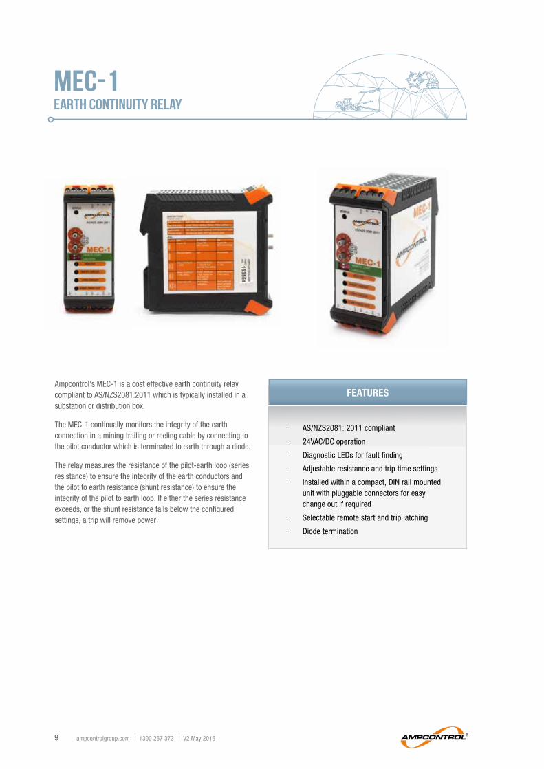
MEC-1earth continuity relay
∙ AS/NZS2081: 2011 compliant
∙ 24VAC/DC operation
∙ Diagnostic LEDs for fault finding
∙ Adjustable resistance and trip time settings
∙ Installed within a compact, DIN rail mounted unit with pluggable connectors for easy change out if required
∙ Selectable remote start and trip latching
∙ Diode termination
Ampcontrol’s MEC-1 is a cost effective earth continuity relay compliant to AS/NZS2081:2011 which is typically installed in a substation or distribution box.
The MEC-1 continually monitors the integrity of the earth connection in a mining trailing or reeling cable by connecting to the pilot conductor which is terminated to earth through a diode.
The relay measures the resistance of the pilot-earth loop (series resistance) to ensure the integrity of the earth conductors and the pilot to earth resistance (shunt resistance) to ensure the integrity of the pilot to earth loop. If either the series resistance exceeds, or the shunt resistance falls below the configured settings, a trip will remove power.
FEaturES
ampcontrolgroup.com | © Ampcontrol 10
SpEcIfIcatIonS
power Supply
Voltage 24VAC/DC ± 20%, 5W
outputs
Relay contacts 1 x CO (NC-COM-NO) 1 x NO
Rating 1A @ 110VAC - 1A @ 30VDC (Resistive)
Earth continuity protection
Series resistance trip settings (± 3Ω)
10Ω, 15Ω, 20Ω, 25Ω, 35Ω, 45Ω
Shunt resistance 1.25kΩ
Trip time settings 50ms, 100ms, 200ms, 300ms, 400ms, 500ms
Optional start button 100Ω, 1%, 5W
Terminating diode 1N5404
Mechanical and Environment
Dimensions (HxWxD) 117 x 45 x 114 mm
Ingress protection IP20
Operating temperature -20°C to + 65°C
Weight 503g
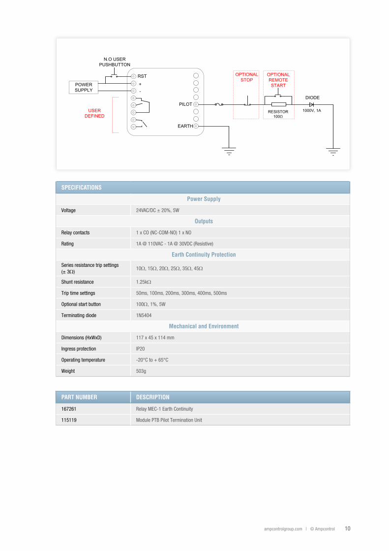
+-
RST
PILOT
EARTH
POWERSUPPLY
OPTIONALSTOP
OPTIONALREMOTESTART
DIODE
N.O USERPUSHBUTTON
RESISTOR100Ω
1000V, 1AUSERDEFINED
paRt nUMBER DEScRIptIon
167261 Relay MEC-1 Earth Continuity
115119 Module PTB Pilot Termination Unit
11 ampcontrolgroup.com | 1300 267 373 | V2 May 2016
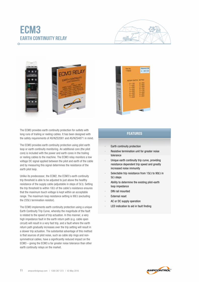
ECM3EARTH continuity RELAY
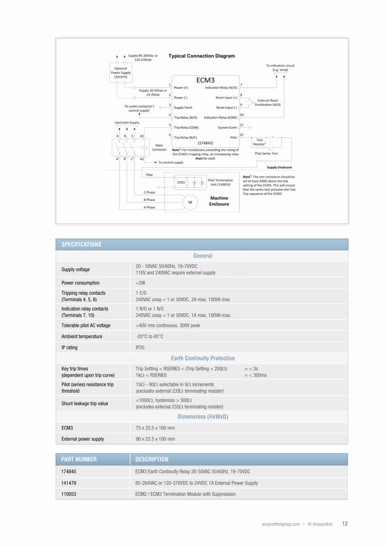
The ECM3 provides earth continuity protection for outlets with long runs of trailing or reeling cables. It has been designed with the safety requirements of AS/NZS2081 and AS/NZS4871 in mind.
The ECM3 provides earth continuity protection using pilot earth loop or earth continuity monitoring. An additional core (the pilot core) is included with the power and earth cores in the trailing or reeling cables to the machine. The ECM3 relay monitors a low voltage DC signal applied between the pilot and earth of the cable and by measuring this signal determines the resistance of the earth pilot loop.
Unlike its predecessor, the ECM2, the ECM3’s earth continuity trip threshold is able to be adjusted to just above the healthy resistance of the supply cable (adjustable in steps of 5Ω). Setting the trip threshold to within 10Ω of the cable’s resistance ensures that the maximum touch voltage is kept within an acceptable range. The maximum loop resistance setting is 90Ω (excluding the 235Ω termination resistor).
The ECM3 implements earth continuity protection using a unique Earth Continuity Trip Curve, whereby the magnitude of the fault is related to the speed of trip actuation. In this manner, a very high impedance fault in the earth return path (e.g. cable open circuit) will result in a very fast trip, and a fault where the earth return path gradually increases over the trip setting will result in a slower trip actuation. The substantial advantage of this method is that sources of pilot noise, such as cable slip rings and non-symmetrical cables, have a significantly reduced impact on the ECM3 – giving the ECM3 a far greater noise tolerance than other earth continuity relays on the market.
∙ Earth continuity protection
∙ Resistive termination unit for greater noise tolerance
∙ Unique earth continuity trip curve, providing resistance dependent trip speed and greatly increased noise immunity
∙ Selectable trip resistance from 15Ω to 90Ω in 5Ω steps
∙ Ability to determine the existing pilot-earth loop impedance
∙ DIN rail mounted
∙ External reset
∙ AC or DC supply operation
∙ LED indication to aid in fault finding
FEaturES
ampcontrolgroup.com | © Ampcontrol 12
SpEcIfIcatIonS
General
Supply voltage20 - 50VAC 50/60Hz, 19-70VDC110V and 240VAC require external supply
Power consumption <2W
Tripping relay contacts (Terminals 4, 5, 6)
1 C/O 240VAC cosφ = 1 or 30VDC, 2A max, 100VA max
Indication relay contacts (Terminals 7, 10)
1 N/O or 1 N/C240VAC cosφ = 1 or 30VDC, 1A max, 100VA max.
Tolerable pilot AC voltage <40V rms continuous, 300V peak
Ambient temperature -20°C to 45°C
IP rating IP20
Earth continuity protection
Key trip times (dependent upon trip curve)
Trip Setting < RSERIES < (Trip Setting + 200Ω) 1kΩ < RSERIES
= < 3s= < 300ms
Pilot (series) resistance trip threshold
15Ω - 90Ω selectable in 5Ω increments(excludes external 235Ω terminating resister)
Shunt leakage trip value <1000Ω, hysteresis > 500Ω(excludes external 235Ω terminating resister)
Dimensions (HxWxD)
ECM3 75 x 22.5 x 100 mm
External power supply 90 x 22.5 x 100 mm
paRt nUMBER DEScRIptIon
174845 ECM3 Earth Continuity Relay 20-50VAC 50/60Hz, 19-70VDC
141479 85-264VAC or 120-370VDC to 24VDC 1A External Power Supply
110053 ECM2 / ECM3 Termination Module with Suppression
13 ampcontrolgroup.com | 1300 267 373 | V2 May 2016
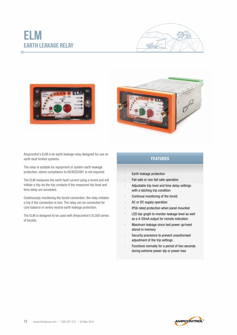
ELMEARTH LEAKAGE RELAY
Ampcontrol’s ELM is an earth leakage relay designed for use on earth fault limited systems.
The relay is suitable for equipment or system earth leakage protection, where compliance to AS/NZS2081 is not required.
The ELM measures the earth fault current using a toroid and will initiate a trip via the trip contacts if the measured trip level and time delay are exceeded.
Continuously monitoring the toroid connection, the relay initiates a trip if the connection is lost. The relay can be connected for core balance or series neutral earth leakage protection.
The ELM is designed to be used with Ampcontrol’s EL500 series of toroids.
∙ Earth leakage protection
∙ Fail safe or non-fail safe operation
∙ Adjustable trip level and time delay settings with a latching trip condition
∙ Continual monitoring of the toroid
∙ AC or DC supply operation
∙ IP56 rated protection when panel mounted
∙ LED bar graph to monitor leakage level as well as a 4-20mA output for remote indication
∙ Maximum leakage since last power up/reset stored in memory
∙ Security provisions to prevent unauthorised adjustment of the trip settings
∙ Functions normally for a period of two seconds during extreme power dip or power loss
FEaturES
ampcontrolgroup.com | © Ampcontrol 14
paRt nUMBER DEScRIptIon
121398 ELM Earth Leakage Relay
101399 DIN Rail Mounting Kit (suit ELD, ELV, ELM)
164672 Lockable Front Cover (suit ELD, ELV, ELM)
120255 ELD-ELC/F Adapter Kit
115438 Toroid – EL500 25mm ID
115439 Toroid – EL500/60mm ID
115440 Toroid – EL500/85mm ID
115441 Toroid – EL500/112mm ID
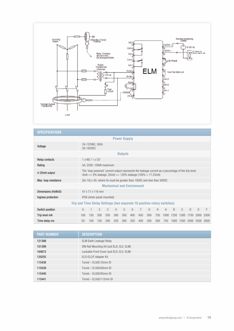
SpEcIfIcatIonS
power Supply
Voltage24-132VAC, 50Hz20-185VDC
outputs
Relay contacts 1 x NO / 1 x CO
Rating 5A, 250V; 100VA maximum
4-20mA outputThe ‘loop powered’ current output represents the leakage current as a percentage of the trip level.4mA => 0% leakage, 20mA => 120% leakage (100% = 17.33mA)
Max. loop resistance [Vs-10] x 50, where Vs must be greater than 10VDC and less than 30VDC
Mechanical and Environment
Dimensions (HxWxD) 47 x 77 x 116 mm
Ingress protection IP56 (when panel mounted)
trip and time Delay Settings (two separate 16 position rotary switches)
Switch position 0 1 2 3 4 5 6 7 8 9 A B C D E F
Trip level mA 100 150 200 250 300 350 400 450 500 750 1000 1250 1500 1750 2000 2500
Time delay ms 50 100 150 200 250 300 350 400 450 500 750 1000 1500 2000 2500 3000
15 ampcontrolgroup.com | 1300 267 373 | V2 May 2016
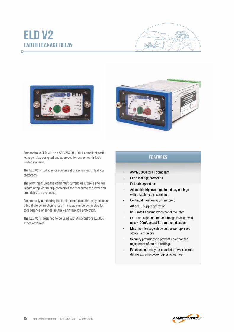
ELD V2EARTH LEAKAGE RELAY
Ampcontrol’s ELD V2 is an AS/NZS2081:2011 compliant earth leakage relay designed and approved for use on earth fault limited systems.
The ELD V2 is suitable for equipment or system earth leakage protection.
The relay measures the earth fault current via a toroid and will initiate a trip via the trip contacts if the measured trip level and time delay are exceeded.
Continuously monitoring the toroid connection, the relay initiates a trip if the connection is lost. The relay can be connected for core balance or series neutral earth leakage protection.
The ELD V2 is designed to be used with Ampcontrol’s EL500S series of toroids.
∙ AS/NZS2081:2011 compliant
∙ Earth leakage protection
∙ Fail safe operation
∙ Adjustable trip level and time delay settings with a latching trip condition
∙ Continual monitoring of the toroid
∙ AC or DC supply operation
∙ IP56 rated housing when panel mounted
∙ LED bar graph to monitor leakage level as well as a 4-20mA output for remote indication
∙ Maximum leakage since last power up/reset stored in memory
∙ Security provisions to prevent unauthorised adjustment of the trip settings
∙ Functions normally for a period of two seconds during extreme power dip or power loss
FEaturES
ampcontrolgroup.com | © Ampcontrol 16
paRt nUMBER DEScRIptIon
115161 ELD V2 Earth Leakage Relay
101399 DIN Rail Mounting Kit (suit ELD, ELV, ELM)
164672 Lockable Front Cover (suit ELD, ELV, ELM)
120255 ELD-ELC/F Adapter Kit
115437 Toroid – 25mm ID
101658 Toroid – 60mm ID
101656 Toroid – 112mm ID
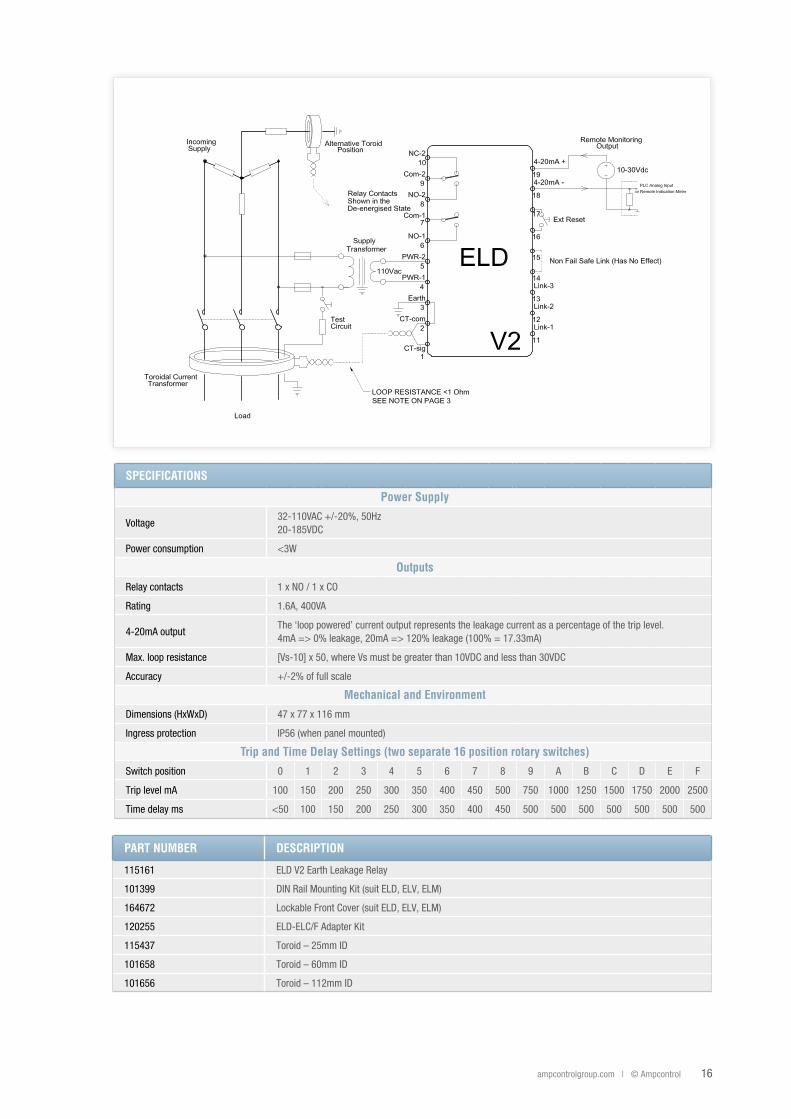
SpEcIfIcatIonS
power Supply
Voltage32-110VAC +/-20%, 50Hz20-185VDC
Power consumption <3W
outputs
Relay contacts 1 x NO / 1 x CO
Rating 1.6A, 400VA
4-20mA outputThe ‘loop powered’ current output represents the leakage current as a percentage of the trip level.4mA => 0% leakage, 20mA => 120% leakage (100% = 17.33mA)
Max. loop resistance [Vs-10] x 50, where Vs must be greater than 10VDC and less than 30VDC
Accuracy +/-2% of full scale
Mechanical and Environment
Dimensions (HxWxD) 47 x 77 x 116 mm
Ingress protection IP56 (when panel mounted)
trip and time Delay Settings (two separate 16 position rotary switches)
Switch position 0 1 2 3 4 5 6 7 8 9 A B C D E F
Trip level mA 100 150 200 250 300 350 400 450 500 750 1000 1250 1500 1750 2000 2500
Time delay ms <50 100 150 200 250 300 350 400 450 500 500 500 500 500 500 500
17 ampcontrolgroup.com | 1300 267 373 | V2 May 2016
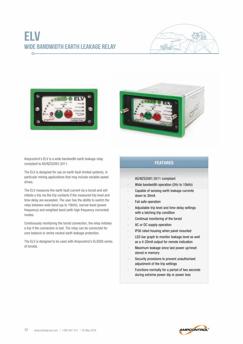
ELVWIDE BANDWIDTH EARTH LEAKAGE RELAY
∙ AS/NZS2081:2011 compliant
∙ Wide bandwidth operation (5Hz to 10kHz)
∙ Capable of sensing earth leakage currents down to 30mA
∙ Fail safe operation
∙ Adjustable trip level and time delay settings with a latching trip condition
∙ Continual monitoring of the toroid
∙ AC or DC supply operation
∙ IP56 rated housing when panel mounted
∙ LED bar graph to monitor leakage level as well as a 4-20mA output for remote indication
∙ Maximum leakage since last power up/reset stored in memory
∙ Security provisions to prevent unauthorised adjustment of the trip settings
∙ Functions normally for a period of two seconds during extreme power dip or power loss
Ampcontrol’s ELV is a wide bandwidth earth leakage relay compliant to AS/NZS2081:2011.
The ELV is designed for use on earth fault-limited systems, in particular mining applications that may include variable speed drives.
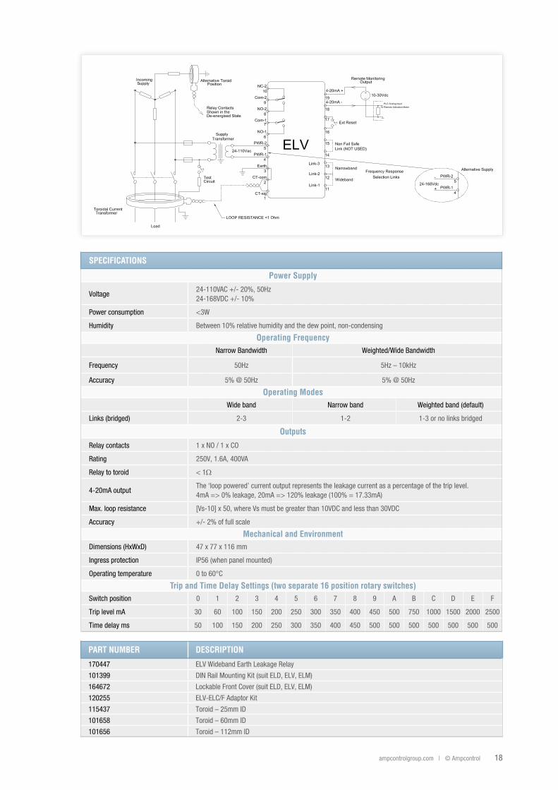
The ELV measures the earth fault current via a toroid and will initiate a trip via the trip contacts if the measured trip level and time delay are exceeded. The user has the ability to switch the relay between wide band (up to 10kHz), narrow band (power frequency) and weighted band (with high frequency corrected) modes.
Continuously monitoring the toroid connection, the relay initiates a trip if the connection is lost. The relay can be connected for core balance or series neutral earth leakage protection.
The ELV is designed to be used with Ampcontrol’s EL500S series of toroids.
FEaturES
ampcontrolgroup.com | © Ampcontrol 18
paRt nUMBER DEScRIptIon
170447 ELV Wideband Earth Leakage Relay
101399 DIN Rail Mounting Kit (suit ELD, ELV, ELM)
164672 Lockable Front Cover (suit ELD, ELV, ELM)
120255 ELV-ELC/F Adaptor Kit
115437 Toroid – 25mm ID
101658 Toroid – 60mm ID
101656 Toroid – 112mm ID
SpEcIfIcatIonS
power Supply
Voltage24-110VAC +/- 20%, 50Hz24-168VDC +/- 10%
Power consumption <3W
Humidity Between 10% relative humidity and the dew point, non-condensing
operating frequencyNarrow Bandwidth Weighted/Wide Bandwidth
Frequency 50Hz 5Hz – 10kHz
Accuracy 5% @ 50Hz 5% @ 50Hz
operating ModesWide band Narrow band Weighted band (default)
Links (bridged) 2-3 1-2 1-3 or no links bridged
outputs
Relay contacts 1 x NO / 1 x CO
Rating 250V, 1.6A, 400VA
Relay to toroid < 1Ω
4-20mA outputThe ‘loop powered’ current output represents the leakage current as a percentage of the trip level. 4mA => 0% leakage, 20mA => 120% leakage (100% = 17.33mA)
Max. loop resistance [Vs-10] x 50, where Vs must be greater than 10VDC and less than 30VDC
Accuracy +/- 2% of full scale
Mechanical and EnvironmentDimensions (HxWxD) 47 x 77 x 116 mm
Ingress protection IP56 (when panel mounted)
Operating temperature 0 to 60°C
trip and time Delay Settings (two separate 16 position rotary switches)Switch position 0 1 2 3 4 5 6 7 8 9 A B C D E F
Trip level mA 30 60 100 150 200 250 300 350 400 450 500 750 1000 1500 2000 2500
Time delay ms 50 100 150 200 250 300 350 400 450 500 500 500 500 500 500 500
19 ampcontrolgroup.com | 1300 267 373 | V2 May 2016
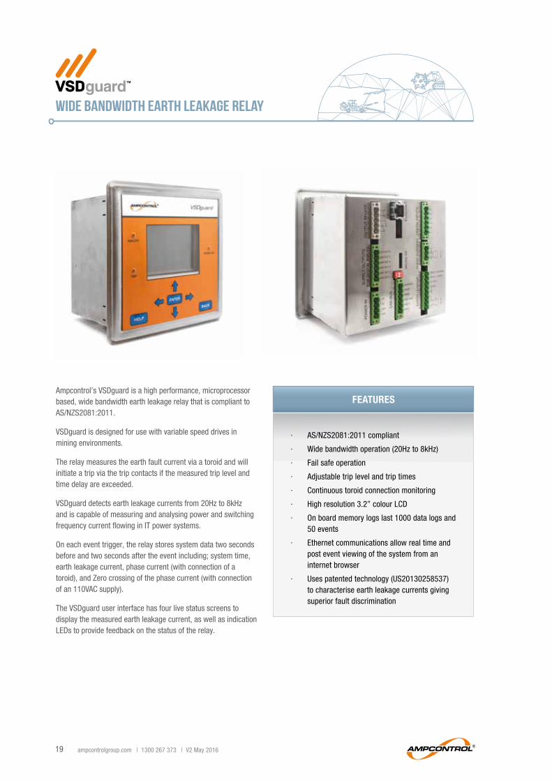
WIDE BANDWIDTH EARTH LEAKAGE RELAY
∙ AS/NZS2081:2011 compliant
∙ Wide bandwidth operation (20Hz to 8kHz)
∙ Fail safe operation
∙ Adjustable trip level and trip times
∙ Continuous toroid connection monitoring
∙ High resolution 3.2” colour LCD
∙ On board memory logs last 1000 data logs and 50 events
∙ Ethernet communications allow real time and post event viewing of the system from an internet browser
∙ Uses patented technology (US20130258537) to characterise earth leakage currents giving superior fault discrimination
Ampcontrol’s VSDguard is a high performance, microprocessor based, wide bandwidth earth leakage relay that is compliant to AS/NZS2081:2011.
VSDguard is designed for use with variable speed drives in mining environments.
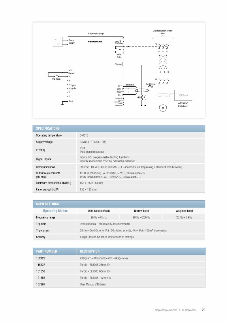
The relay measures the earth fault current via a toroid and will initiate a trip via the trip contacts if the measured trip level and time delay are exceeded.
VSDguard detects earth leakage currents from 20Hz to 8kHz and is capable of measuring and analysing power and switching frequency current flowing in IT power systems.
On each event trigger, the relay stores system data two seconds before and two seconds after the event including; system time, earth leakage current, phase current (with connection of a toroid), and Zero crossing of the phase current (with connection of an 110VAC supply).
The VSDguard user interface has four live status screens to display the measured earth leakage current, as well as indication LEDs to provide feedback on the status of the relay.
FEaturES
ampcontrolgroup.com | © Ampcontrol 20
VSDGuard
A B C
CB
NER
MC
Mine reticulation system (HV)
M
Earth
ELCT1ELCT2
ELT2
test signal
24V Source6
5
4
3
VSDGUARD
ELT1
2
1
AlternativeInstallation
Trip Reset
Digital Inputs
Test Circuit
Power Supply
Parameter Storage
Mech. Relay
Ethernet
S.S Relay
Optional Zero Crossing
Optional Phase Current
Measurement
USER SEttInGS
operating Modes Wide band (default) Narrow band Weighted band
Frequency range 20 Hz – 8 kHz 20 Hz – 200 Hz 20 Hz – 8 kHz
Trip time Instantaneous – 500ms in 50ms increments
Trip current 50mA – 5A (50mA to 1A in 50mA increments, 1A – 5A in 100mA increments)
Security 4 digit PIN can be set to limit access to settings
paRt nUMBER DEScRIptIon
162129 VSDguard – Wideband earth leakage relay
115437 Toroid - EL500S 25mm ID
101658 Toroid - EL500S 60mm ID
101656 Toroid - EL500S 112mm ID
167291 User Manual VSDGuard
SpEcIfIcatIonS
Operating temperature 0-60°C
Supply voltage 24VDC (+/-25%) (12W)
IP ratingIP20IP55 (panel mounted)
Digital inputsInputs 1-5: programmable trip/log functionsInput 6: manual trip reset by external pushbutton
Communications Ethernet: 10BASE-TX or 100BASE-TX - accessible via http (using a standard web browser).
Output relay contacts(fail safe)
1xCO (mechanical) 6A / 250VAC, 50VDC, 300VA (cosø=1)1xNO (solid state) 2.9A / 110VAC/DC, 100VA (cosø=1)
Enclosure dimensions (HxWxD) 155 x155 x 113 mm
Panel cut-out (HxW) 135 x 135 mm

Ampcontrol’s hard rock relay range | © Ampcontrol | V2 May 2016
ampcontrol Head office
21 Old Punt Road,Tomago NSW 2322Phone: 1300 267 373 [email protected]
ampcontrolgroup.com