AlternAtors, AC InduCtIon motors, synChronous motors, … · · 2016-09-01Tree-diagram of...
14
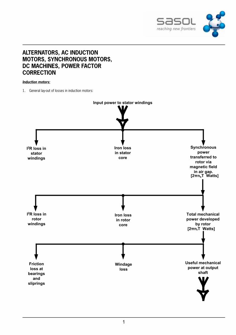
1 ALTERNATORS, AC INDUCTION MOTORS, SYNCHRONOUS MOTORS, DC MACHINES, POWER FACTOR CORRECTION Induction motors: 1. General lay-out of losses in induction motors: Input power to stator windings I 2 R loss in stator windings Iron loss in stator core Synchronous power transferred to rotor via magnetic field in air gap. [2πn s T Watts] I 2 R loss in rotor windings Iron loss in rotor core Total mechanical power developed by rotor [2πn r T Watts] Useful mechanical power at output shaft Windage loss Friction loss at bearings and sliprings
Transcript of AlternAtors, AC InduCtIon motors, synChronous motors, … · · 2016-09-01Tree-diagram of...
1
AlternAtors, AC InduCtIon motors, synChronous motors, dC mAChInes, Power fACtor CorreCtIonInduction motors:
1. General lay-out of losses in induction motors:
Input power to stator windings
I2R loss instator
windings
Iron lossin stator
core
Synchronouspower
transferred torotor via
magnetic fieldin air gap.
[2πnsT Watts]
I2R loss inrotor
windings
Iron lossin rotor
core
Total mechanicalpower developed
by rotor[2πnrT Watts]
Useful mechanicalpower at output
shaft
Windageloss
Frictionloss at
bearingsand
sliprings
2
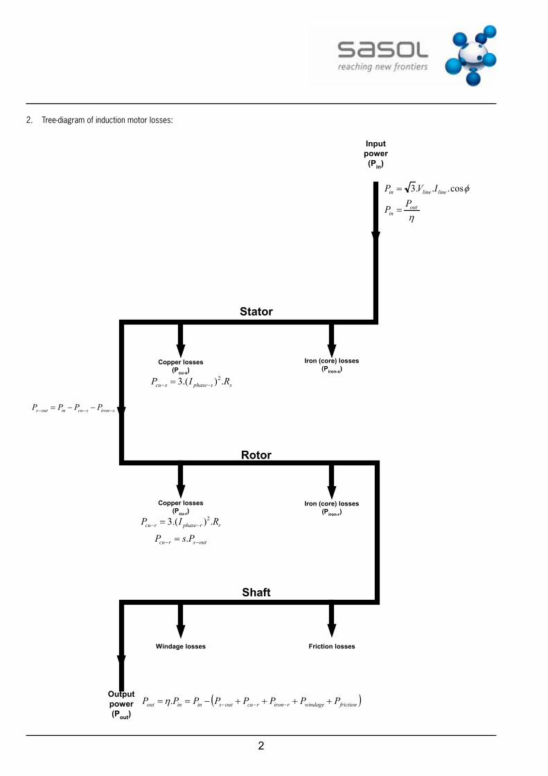
2. Tree-diagram of induction motor losses:
Stator
Rotor
Shaft
Copper losses(Pcu-s)
Iron (core) losses(Piron-s)
Copper losses(Pcu-r)
Iron (core) losses(Piron-r)
Windage losses Friction losses
Outputpower(Pout)
Inputpower(Pin)
ssphasescu RIP .).(3 2−− =
sironscuinouts PPPP −−− −−=
rrphasercu RIP .).(3 2−− =
φcos...3 linelinein IVP =
ηout
inPP =
outsrcu PsP −− = .
( )frictionwindagerironrcuoutsininout PPPPPPPP ++++−== −−−.η
3
3. p.u slip (s) = n
n ns
s r- where ns is the synchronous speed of
the motor and nr is the rotor speed of the motor.
4. Slip-speed = s ns$
5. n n slipspeedr s= =
6. f pn=
7. f s p nr $ $=
8. Rotor emf/phase at standstill: 2.22E k fp0 $ $ $ z= where kd is the distribution factor with:
. sin
sink
n
n
2
2d a
a
= and kp is the pitch factor with cosk2p}
=
n= number of slots/pole/phase
a= slots per pole
1800
}= (1 – coil pitch as a fraction of the pole pitch) x 180°
9. Z R Xrotor rotor2 2= + where Xrotor is the leakage reactance
per phase.
10. X s Xrotor 0$=
11. IZE
Zs E
rotorrotor
rotor
rotor
0$= = and tan
RX
Rs X
rotorrotor 0$
z = =
and cosZR
rotorrotor
z =
where: E0 = voltage per phase of stator X0 = reactance per phase at no-load
12. IR X
E0 2
02
0=+
13. Total I R2 losses in rotor = s Pcu out$ - = slipspeed T T2 rotor rotor 1 2$ $r ~ ~= -^ h
Where: n2 S1 $ $~ r= and n2 r2 $ $~ r=
14. Torque characteristics:
• p.u torque reduction to rotor:
TR s X
s E R
R s X
s R2
02
02
20
2
2
\$
$ $\
$
$ $z
+ +^ ^h h
• At maxumum torque:
R s X0$=
• Torque on rotor varies as (stator applied voltage)2
• Direct switching to supply:
TT
II
sfull load
starting
full load
short circuitfull load
2
$=- -
--c m
•• Star-delta starter:
TT
II
s31
full load
starting
full load
short circuitfull load
2
$=- -
--c m
• Motor speed at maximum torque = pf
s1 -^ h rev/s where
f is the rotational frequency, p is the pair of poles and s is the p.u. slip of the motor.
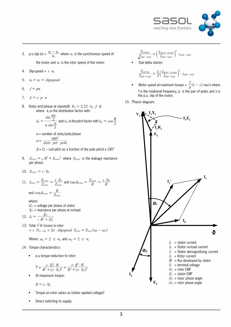
15. Phasor diagram:
Ø1
Ø2
Ф
I1I1'
I0
E1
V1I1X1
I1R1
I1Z1
E2
I2
I1 = stator currentI0 = Stator no-load currentI'1 = Stator demagnetizing currentI2 = Rotor currentU = flux developed by statorV1 = terminal voltageE2 = rotor EMFE1 = stator EMF
1Q = staor phase angle2Q = rotor phase angle
4
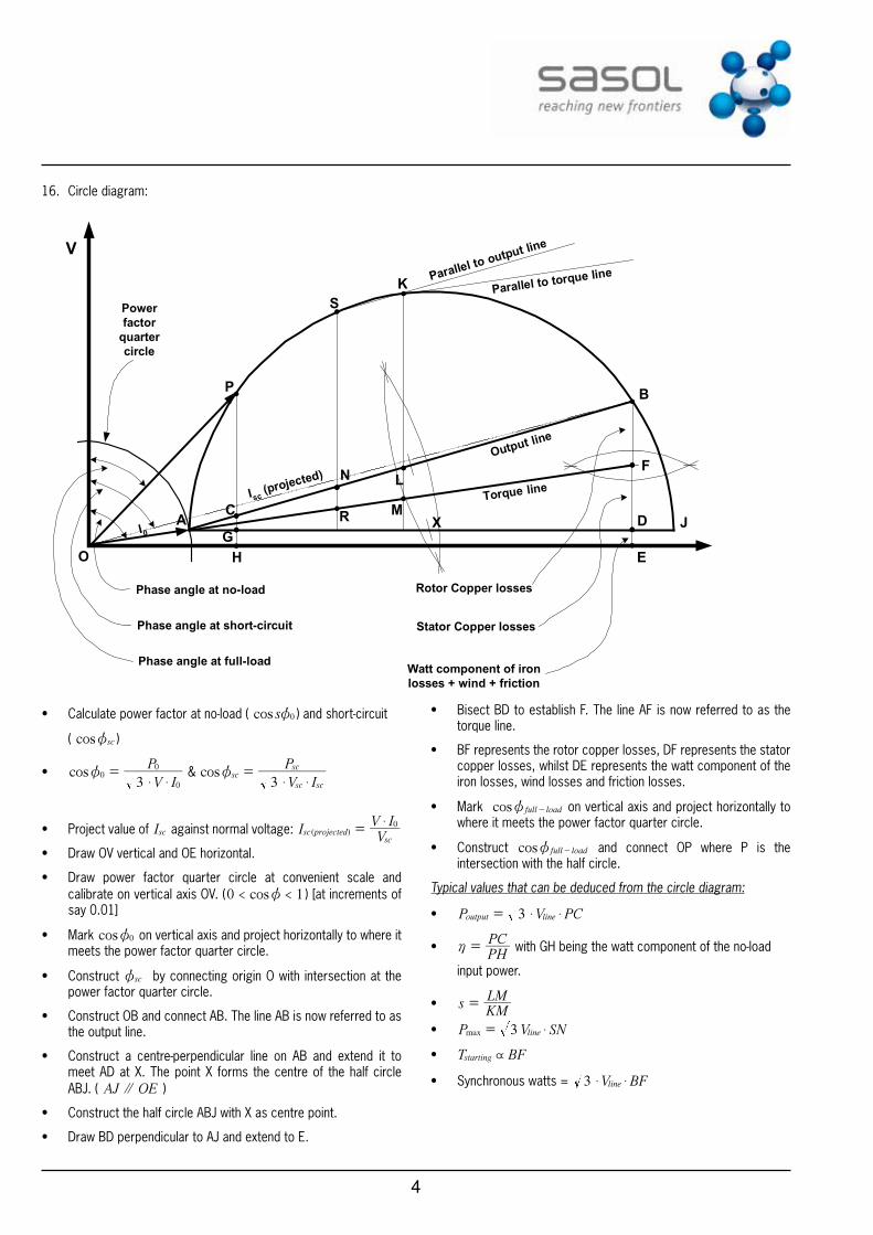
16. Circle diagram:
O
P
SK
B
F
D
E
JXM
LN
RC
GH
AI0
V
Torque line
Output line
Parallel to torque lineParallel to output line
Isc (projected)
Powerfactor
quartercircle
Phase angle at no-load
Phase angle at short-circuit
Phase angle at full-load
Rotor Copper losses
Stator Copper losses
Watt component of ironlosses + wind + friction
• Calculate power factor at no-load ( cos s 0z ) and short-circuit
( cos scz )
• cosV I
P
30
0
0
$ $z = & cos
V I
P
3sc
sc sc
sc
$ $z =
• Project value of Isc against normal voltage: IVV I
( )sc projectedsc
0$=
• Draw OV vertical and OE horizontal.
• Draw power factor quarter circle at convenient scale and calibrate on vertical axis OV. ( cos0 1< <z ) [at increments of say 0.01]
• Mark cos 0z on vertical axis and project horizontally to where it meets the power factor quarter circle.
• Construct scz by connecting origin O with intersection at the power factor quarter circle.
• Construct OB and connect AB. The line AB is now referred to as the output line.
• Construct a centre-perpendicular line on AB and extend it to meet AD at X. The point X forms the centre of the half circle ABJ. ( AJ OE' )
• Construct the half circle ABJ with X as centre point.
• Draw BD perpendicular to AJ and extend to E.
• Bisect BD to establish F. The line AF is now referred to as the torque line.
• BF represents the rotor copper losses, DF represents the stator copper losses, whilst DE represents the watt component of the iron losses, wind losses and friction losses.
• Mark cos full loadz - on vertical axis and project horizontally to where it meets the power factor quarter circle.
• Construct cos full loadz - and connect OP where P is the intersection with the half circle.
Typical values that can be deduced from the circle diagram:
• P V PC3output line$ $=
•PHPC
h = with GH being the watt component of the no-load
input power.
• sKMLM=
• P V SN3max line $=
• T BFstarting \
• Synchronous watts = V BF3 line$ $
5
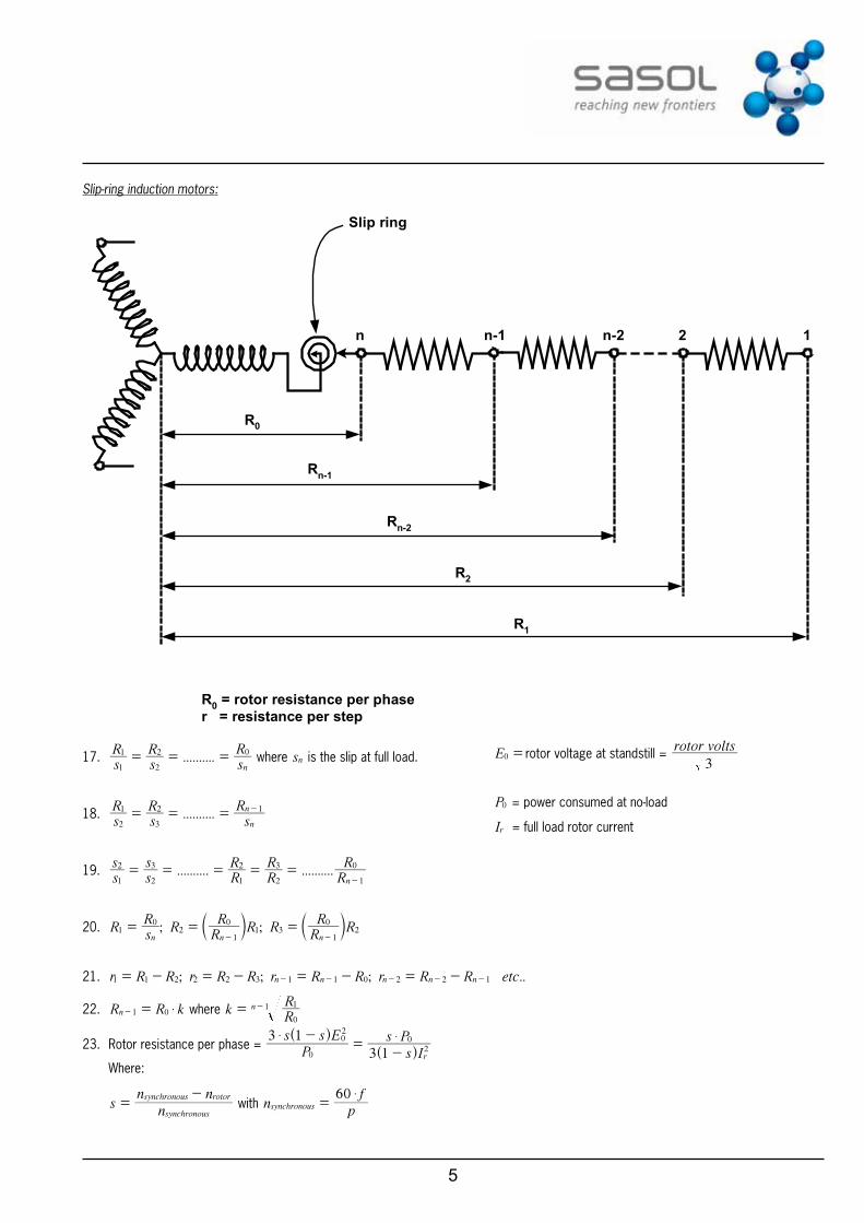
Slip-ring induction motors:
Slip ring
n n-1 n-2 2 1
R0
Rn-1
Rn-2
R2
R1
R0 = rotor resistance per phaser = resistance per step
17. ..........sR
sR
sRn1
1
2
2 0= = = where sn is the slip at full load.
18. ..........sR
sR
sR
n
n
2
1
3
2 1= = = -
19. .......... ..........ss
ss
RR
RR
RRn1
2
2
3
1
2
2
3
1
0= = = = =-
20. ; ;RsR
RRR
R RRR
Rn n n
10
21
01 3
1
02= = =
- -c cm m
21. ; ; ; ..r R R r R R r R R r R R etcn n n n n1 1 2 2 2 3 1 1 0 2 2 1= - = - = - = -- - - - -
22. R R kn 1 0 $=- where kRRn
0
11= -
23. Rotor resistance per phase = P
s s E
s Is P3 1
3 1 r0
02
20$ $-
=-
^^
hh
Where:
sn
n n
synchronous
synchronous rotor=
- with n
pf60
synchronous
$=
E0 = rotor voltage at standstill = rotor volts3
P0 = power consumed at no-load
Ir = full load rotor current
6
24. f p n$=
25. RMS value of EMF per phase = . k k Z f2 22 d p$ $ $ $ $ z
26. sin
sink
n
n
2
2d
$
$
a
a
=
where:
n = the number of slots per pole per phasea = pole pitch
27. cosk2p}
= where } is the angle of short pitch coil.
28. degrees electrical = p x degrees mechanical
29. Parallel operation:
E1
E2
V
Z S1
Z S2
I1
I2
I total
30. V E I ZS1 1 1$= - or V E I ZS2 2 2$= -
31. IZ
E VS
11
1=-
and IZ
E VS
22
2=-
32. IZ Z Z Z Z
E Z E Ztotal
S S S S
S S
1 2 1 2
1 2 2 1=+ +
+^ h
33. Circulating current: IZ ZE E
CS S1 2
1 2=+-
DC Machines
34. Ec
p Z N60
2 $ $ $ $z= and T
cI Z pa
$
$ $ $
r
z=
35. P N TE I
602
a$ $ $
$r= =
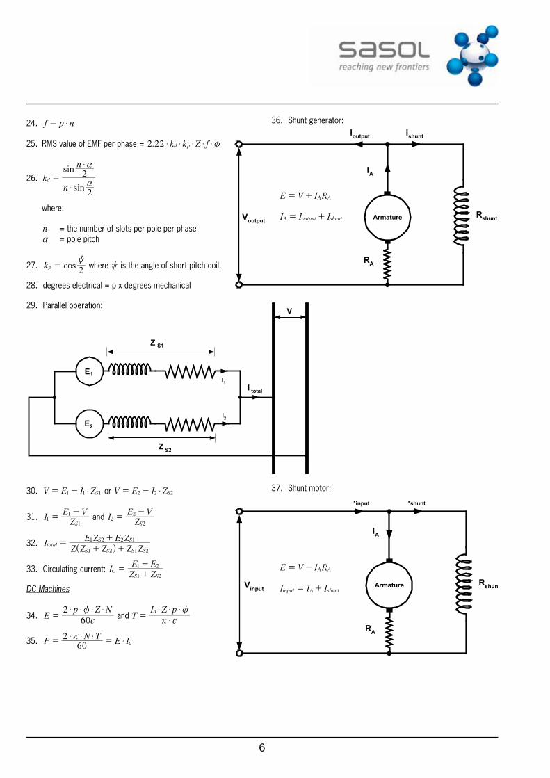
36. Shunt generator:
Armature Rshunt
RA
IA
Ioutput Ishunt
Voutput
E V I RA A= +
I I IA output shunt= +
37. Shunt motor:
Armature Rshunt
RA
IA
Iinput Ishunt
Vinput
E V I RA A= -
I I Iinput A shunt= +
7
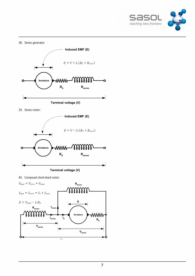
38. Series generator:
Armature
RA Rseries
Terminal voltage (V)
Induced EMF (E)
E V I R RA A series= + +^ h
39. Series motor:
Armature
RA Rseries
Terminal voltage (V)
Induced EMF (E)
E V I R RA A series= - +^ h
40. Compound short-shunt motor:
Armature
Rseries
Rshunt
RA
Vinput
E
Vseries
Vshunt
Iseries
Ishunt
IA
V V Vinput series shunt= +
I I I Iinput series A shunt= = +
E V I Rshunt A A= -
8
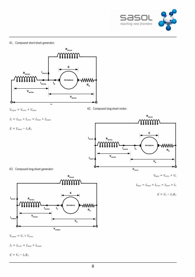
41. Compound short-shunt generator:
Armature
Rseries
Rshunt
RA
Voutput
E
Vseries
Vshunt
Iseries
Ishunt
IA
V V Voutput series shunt= +
I I I I IA shunt series shunt output= + = +
E V I Rshunt A A= -
42. Compound long-shunt motor:
Armature
Rseries
Rshunt
RA
Vinput
E
Vseries
Iseries
Ishunt
IA
IinputVA
V V Vinput series A= +
I I I I Iinput shunt series shunt A= + = +
E V I RA A A= -
43. Compound long-shunt generator:
Armature
Rseries
Rshunt
RA
Voutput
E
Vseries
Iseries
Ishunt
IA
IoutputVA
V V Voutput A series= +
I I I IA series shunt output= = +
E V I RA A A= -
9
44. Articulated scenarios:
Ec
p Z N60
2 $ $ $ $z= and T
cI Z pa
$
$ $ $
r
z=
keeping p, Z & c constant:
E NEE
NN
2
1
2 2
1 1&\ z
zz
= and T ITT
II
aa
a
2
1
2
1
2
1
&\ $$$
zzz
=
Keeping the flux constant as well:
E NEE
NN
2
1
2
1&\ =
45. Efficiencies of DC machines:
efficiencyinputoutput
= and input output losses- =
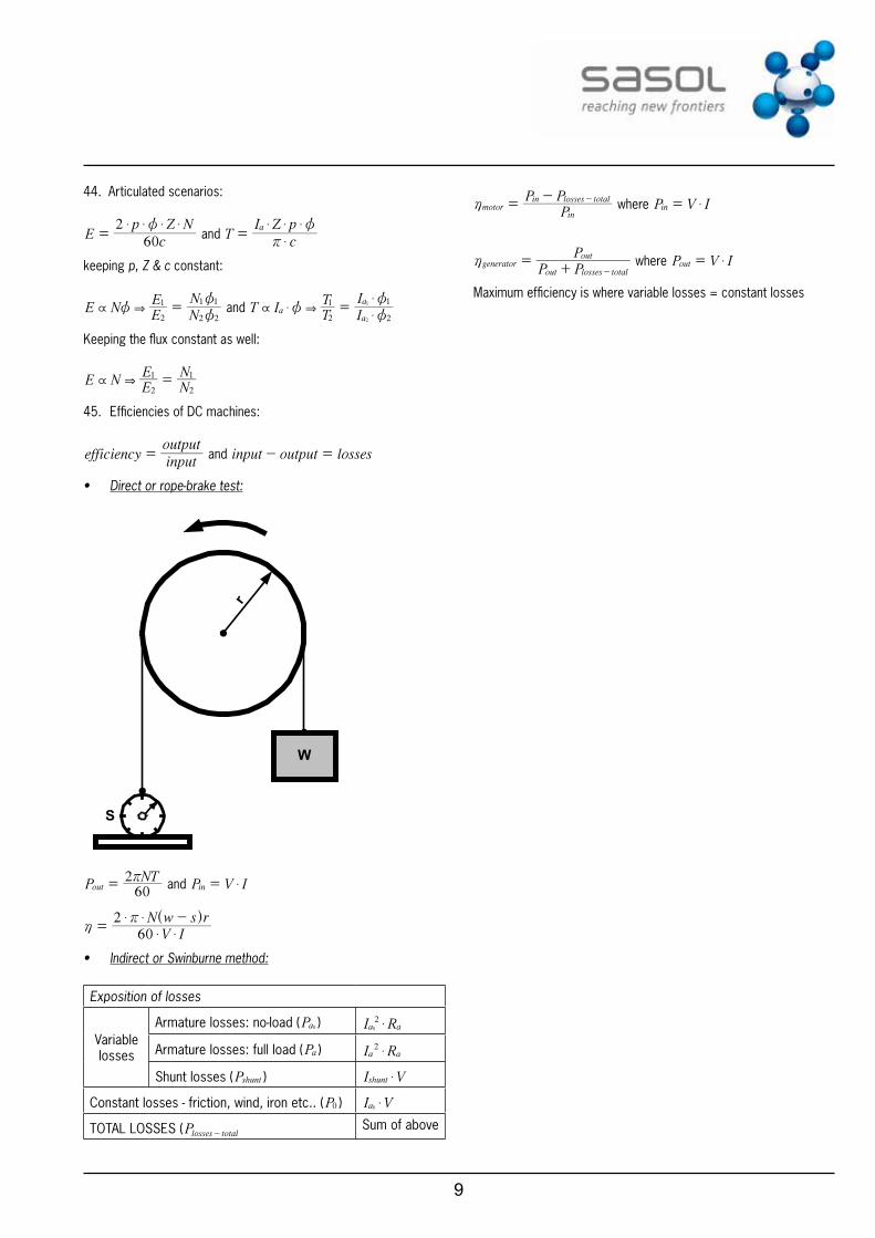
• Direct or rope-brake test:
W
r
S
PNT60
2out
r= and P V Iin $=
V IN w s r
602
$ $
$ $h
r=
-^ h
• Indirect or Swinburne method:
Exposition of losses
Variable losses
Armature losses: no-load (Pa0 ) I Ra a20 $
Armature losses: full load (Pa ) I Ra a2 $
Shunt losses (Pshunt ) I Vshunt $
Constant losses - friction, wind, iron etc.. (P0 ) I Va0 $
TOTAL LOSSES (Plosses total-Sum of above
PP P
motorin
in losses totalh =
- - where P V Iin $=
P PP
generatorout losses total
outh =
+ - where P V Iout $=
Maximum efficiency is where variable losses = constant losses
10
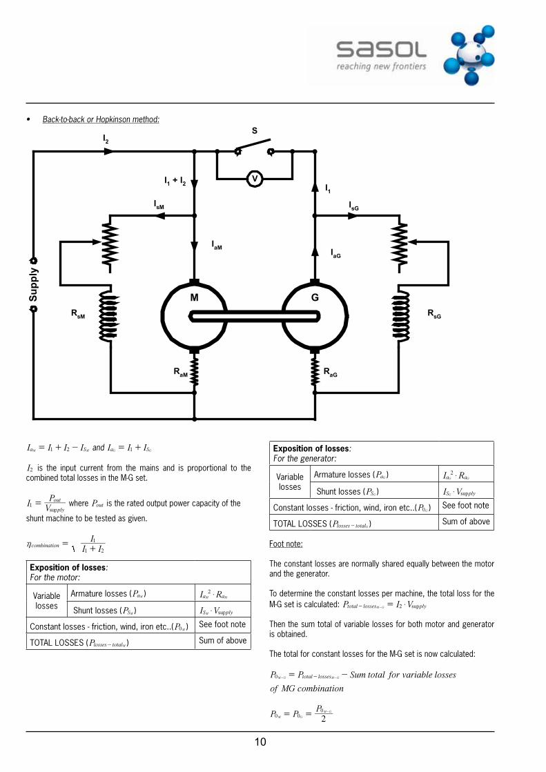
• Back-to-back or Hopkinson method:
V
Supp
ly
M G
SI2
I1
IaG
IsG
IaM
IsM
I1 + I2
RsM RsG
RaM RaG
I I I Ia S1 2M M= + - and I I Ia S1G G= +
I2 is the input current from the mains and is proportional to the combined total losses in the M-G set.
IVPsupply
out1 = where Pout is the rated output power capacity of the
shunt machine to be tested as given.
I II
combination1 2
1h =
+
exposition of losses:For the motor:
Variable losses
Armature losses (PaM ) I Ra a2
M M$
Shunt losses (PSM ) I VsupS plyM $
Constant losses - friction, wind, iron etc..(P0M ) See foot note
TOTAL LOSSES (Plosses totalM- ) Sum of above
exposition of losses:For the generator:
Variable losses
Armature losses (PaG ) I Ra a2G G$
Shunt losses (PSG ) I VsupS plyG $
Constant losses - friction, wind, iron etc..(P0G ) See foot note
TOTAL LOSSES (Plosses totalG- ) Sum of above
Foot note:
The constant losses are normally shared equally between the motor and the generator.
To determine the constant losses per machine, the total loss for the M-G set is calculated: P I Vsuptotal losses ply2M G $=- -
Then the sum total of variable losses for both motor and generator is obtained.
The total for constant losses for the M-G set is now calculated:
P P Sum total for variable losses
of MG combination
total losses0M G M G= --- -
P PP20 00
M G
M G= = -
11
Individual efficiencies:
Due to the motor being mechanically linked to the generator, the rated output of the generator = rated input to the motor = the rated power capacity of the M-G set as given.
Thus: P P rated power capacity of MGsetinput outputM G= =
PP P
motorinput
input losses total
M
M M
h =- -
P P
Pgenerator
input losses total
output
G G
G
h =+ -
Power factor correction:
46. Capacitors
Series arrangement: ....C C C C1 1 1 1total n1 2
= + + +
Parallel arrangement: .......C C C Ctotal n1 2= + + +
Q C V$=
Time constant: R C$x =
Transient period: 5x (average time to charge or discharge)
General instantaneous value:
v V V V efinal initial final
t= + + x
-^ h
i I I I efinal initial final
t= + + x
-^ h
Instantaneous value during charging (beginning at zero):
v V e1final
t= - x
-^ h
i I e1final
t= - x
-^ h
Instantaneous value during discharging (ending at zero):
v V einitial
t
$= x-
i I einitial
t
$= x-
47. Conditions for resonance: X XC L=
48. Xf C21
C $r= and X f L2L $r=
49. Resonant frequency: fL C2
1r
$r=
50. Harmonics in complex waves:
• Basics on phase displacement:
:
cos sin sin
cos sin
t t t
t t where f
2 2
22
&~ ~r
~r
~ ~r
~ r
= + =- -
- = - =
` `
`
j j
j
• Influence of odd-harmonics on reactance: ( f = fundamental frequency).
Fundamental: Xf C21
C1 $r= and X f L2L1 $r=
3rd Harmonic: Xf C2 3
1C3 $ $r= and X f L2 3L3 $ $r=
5th Harmonic: Xf C2 5
1C5 $ $r= and X f L2 5L5 $ $r=
7th Harmonic: Xf C2 7
1C7 $ $r= and X f L2 7L7 $ $r=
9th Harmonic: Xf C2 9
1C9 $ $r= and X f L2 9L9 $ $r=
etc......
• Influence of odd-harmonics on overall power: Refer to notation of instantaneous values:
...
sin sin
sin
e E t E t
E t etc
3
5
max max
max
3
5
1 3
5
~ ~ b
~ b
= + +
+ +
^
^
h
h
and:
..
sin sin
sin
i I t I t
I t etc
3
5
max max
max
1 3
5
1 2
5
~ a ~ a
~ a
= + + +
+ +
^ ^
^
h h
h
Now:
Power of fundamental:
cosP E I2
1max max1 11 1$ $ z= ^ h where cos 1 1 1z b a= -
Power of 3rd harmonic:
cosP E I2
1max max3 33 3$ $ z= ^ h where cos 3 3 3z b a= -
Power of 5th harmonic:
cosP E I2
1max max5 55 5$ $ z= ^ h where cos 5 5 5z b a= -
etc....
12
Total power supplied:
.....P P P P Ptotal n1 3 5= + + + +
.......V
E E E E2RMS
2 2 2 2max max max max5 n1 3=+ + + +
.......I
I I I I2RMS
2 2 2 2max max max max5 n1 3=+ + + +
Overall power factor:
cosV I
PRMS RMS
total
$z =
51. Resonant frequency of an electrical cable network:
f x fr $= with f being the fundamental frequency and x being a multiple of the fundamental frequency.
xMVAMVA
XX
C R
SC R
SC
C= =-
- where MVASC R- is the short circuit
duty at the point of connection; MVAC R- is the capacitor rating at the system voltage; XC is the capacitive reactance of the capacitors at fundamental frequency, and XSC is the short circuit reactance at the point of connection.
52. Active current: cosI z
53. Reactive current: sinI z
54. Active power in 3-phase circuits: cosP V I3active line line$ z=
55. Apparent power in 3-phase circuits: P V I3apparent line line$ $=
56. Power factor: PPapparent
active
57. Reactive component for a balanced inductive load (3-wire):
φ
φcos.3 linelineactive IVP =
line
line
apparent
IV
P
..3=
φsin
.3
lineline
reactiveI
VP
=
sinP V I3reactive line line$ $ $ z=
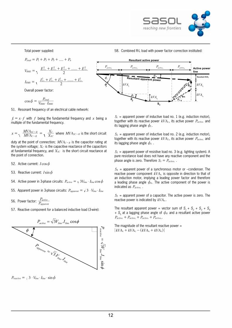
58. Combined R-L load with power factor correction instituted:
S1
S2
S3
S 4
S5
Effecti
ve co
rrecti
on effo
rt
Resultant apparent powerResultant KVAr
Active powerline
1φ
2φ4φ
Rφ
1rkVA
2rkVA 4r
kVA
5rkVA
1activeP2activeP
3activeP4activeP
Resultant active power
S1 = apparent power of inductive load no. 1 (e.g. induction motor), together with its reactive power kVAr1 , its active power Pactive1 and its lagging phase angle 1z .
S2 = apparent power of inductive load no. 2 (e.g. induction motor), together with its reactive power kVA2 , its active power Pactive2 and its lagging phase angle 2z .
S3 = apparent power of resistive load no. 3 (e.g. lighting system). A pure resistance load does not have any reactive component and the phase angle is zero. Therefore S Pactive3 3
= .
S4 = apparent power of a synchronous motor or –condenser. The reactive power component kVAr4 is opposite in direction to that of an induction motor, implying a leading power factor and therefore a leading phase angle 4z . The active component of the power is indicated as Pactive4 .
S5 = apparent power of a capacitor. The active power is zero. The reactive power is indicated by kVAr5 .
The resultant apparent power = vector sum of S1 + S2 + S3 + S4 + S5 at a lagging phase angle of Rz and a resultant active power P P P Pactive active active active1 2 3 4
+ + + .
The magnitude of the resultant reactive power =kVA kVA kVA kVAr r r r1 2 4 5
+ - +^ h
13
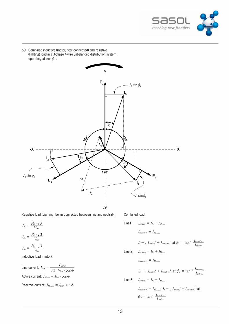
59. Combined inductive (motor, star connected) and resistive(lighting) load in a 3-phase 4-wire unbalanced distribution system operating at cosz .
E3
E1E2
I3
I1
I2
-X X
Y
-Y
120°
120°
120°
3φ
2φ1φ
I2
I 3
I n
33 sinφI
11 sinφI
22 sinφI
Resistive load (Lighting, being connected between line and neutral):
IV
P 3R
line
R1
1 $=
IV
P 3R
line
R2
2 $=
IV
P 3R
line
R3
3 $=
Inductive load (motor):
Line current: cos
IV
P
3line
line
input
$ $ z=
Active current: cosI IM lineactive $ z=
Reactive current: sinI IM linereactive $ z=
Combined load:
Line1: I I Iactive R Mactive1 1= +
I Ireactive Mreactive1=
I I Iactive reactive12 21 1
- + at tanIIactive
reactive1
1
1
1
z = -
Line 2: I I Iactive R Mactive2 2= +
I Ireactive Mreactive2=
I I Iactive reactive22 22 2
- + at tanIIactive
reactive2
1
2
2
z = -
Line 3: I I Iactive R Mactive3 3= +
I Ireactive Mreactive3= ; I I Iactive reactive3
2 23 3
- + at
tanIIactive
reactive3
1
3
3
z = -
14
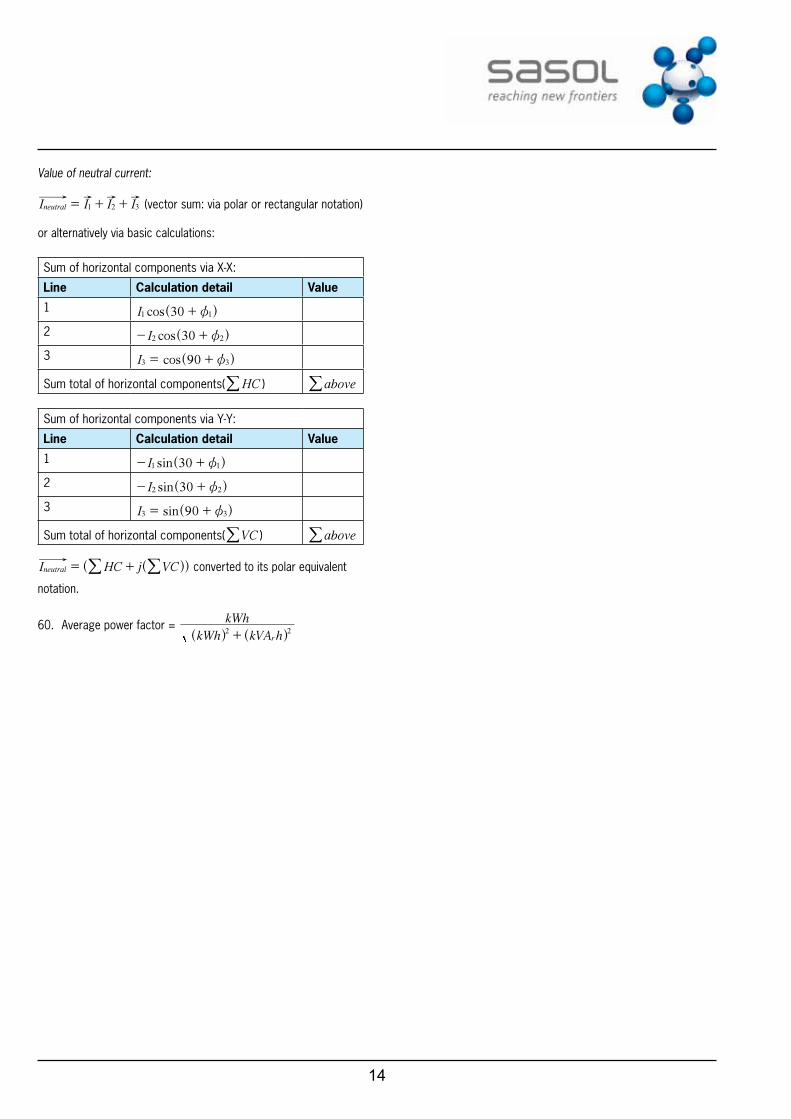
Value of neutral current:
I I I Ineutral 1 2 3= + + (vector sum: via polar or rectangular notation)
or alternatively via basic calculations:
Sum of horizontal components via X-X:
line Calculation detail Value
1 cosI 301 1z+^ h
2 cosI 302 2z- +^ h
3 cosI 903 3z= +^ h
Sum total of horizontal components( HC/ ) above/
Sum of horizontal components via Y-Y:
line Calculation detail Value
1 sinI 301 1z- +^ h
2 sinI 302 2z- +^ h
3 sinI 903 3z= +^ h
Sum total of horizontal components( VC/ ) above/
HC j VCIneutral = + ^^ hh// converted to its polar equivalent
notation.
60. Average power factor = kWh kVA h
kWh
r2 2+^ ^h h