Alternate Ignition Sources for Fire Blocking Barrier … 2 Barrier K Evaluated With Wooden Crib...
27
Transcript of Alternate Ignition Sources for Fire Blocking Barrier … 2 Barrier K Evaluated With Wooden Crib...
UNITED STATES CONSUMER PRODUCT SAFETY COMMISSION WASHINGTON, DC 20207
Memorandum
CPSC Hotline: 1-800-638-CPSC (2772) Η CPSC's Web Site: http://www.cpsc.gov
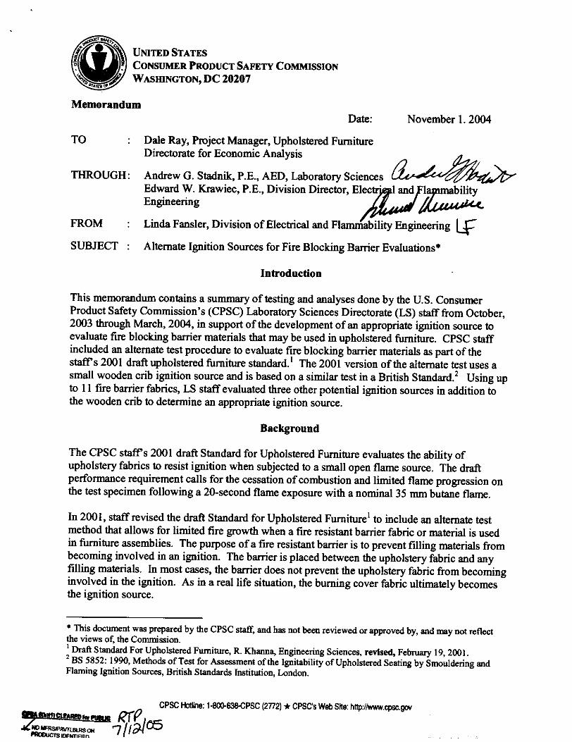
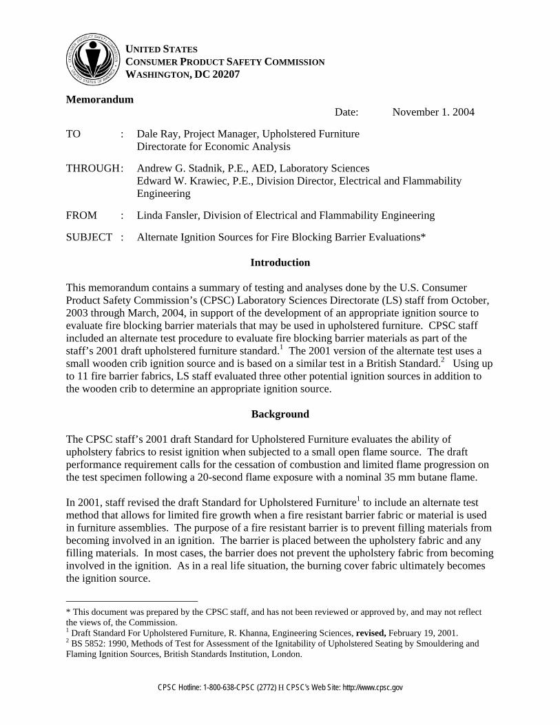
Date: November 1. 2004
TO : Dale Ray, Project Manager, Upholstered Furniture Directorate for Economic Analysis
THROUGH : Andrew G. Stadnik, P.E., AED, Laboratory Sciences Edward W. Krawiec, P.E., Division Director, Electrical and Flammability Engineering
FROM : Linda Fansler, Division of Electrical and Flammability Engineering
SUBJECT : Alternate Ignition Sources for Fire Blocking Barrier Evaluations*
Introduction This memorandum contains a summary of testing and analyses done by the U.S. Consumer Product Safety Commission’s (CPSC) Laboratory Sciences Directorate (LS) staff from October, 2003 through March, 2004, in support of the development of an appropriate ignition source to evaluate fire blocking barrier materials that may be used in upholstered furniture. CPSC staff included an alternate test procedure to evaluate fire blocking barrier materials as part of the staff’s 2001 draft upholstered furniture standard.1 The 2001 version of the alternate test uses a small wooden crib ignition source and is based on a similar test in a British Standard.2 Using up to 11 fire barrier fabrics, LS staff evaluated three other potential ignition sources in addition to the wooden crib to determine an appropriate ignition source.
Background
The CPSC staff’s 2001 draft Standard for Upholstered Furniture evaluates the ability of upholstery fabrics to resist ignition when subjected to a small open flame source. The draft performance requirement calls for the cessation of combustion and limited flame progression on the test specimen following a 20-second flame exposure with a nominal 35 mm butane flame. In 2001, staff revised the draft Standard for Upholstered Furniture1 to include an alternate test method that allows for limited fire growth when a fire resistant barrier fabric or material is used in furniture assemblies. The purpose of a fire resistant barrier is to prevent filling materials from becoming involved in an ignition. The barrier is placed between the upholstery fabric and any filling materials. In most cases, the barrier does not prevent the upholstery fabric from becoming involved in the ignition. As in a real life situation, the burning cover fabric ultimately becomes the ignition source.
* This document was prepared by the CPSC staff, and has not been reviewed or approved by, and may not reflect the views of, the Commission. 1 Draft Standard For Upholstered Furniture, R. Khanna, Engineering Sciences, revised, February 19, 2001. 2 BS 5852: 1990, Methods of Test for Assessment of the Ignitability of Upholstered Seating by Smouldering and Flaming Ignition Sources, British Standards Institution, London.
-2-
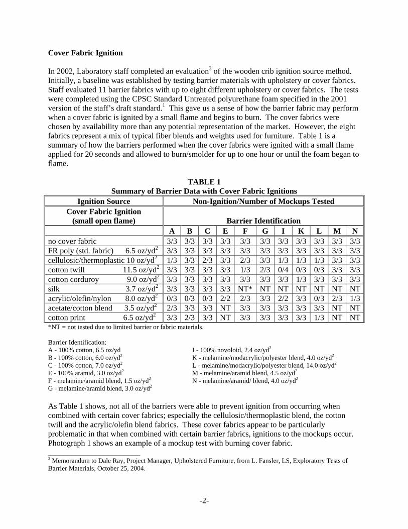
Cover Fabric Ignition In 2002, Laboratory staff completed an evaluation3 of the wooden crib ignition source method. Initially, a baseline was established by testing barrier materials with upholstery or cover fabrics. Staff evaluated 11 barrier fabrics with up to eight different upholstery or cover fabrics. The tests were completed using the CPSC Standard Untreated polyurethane foam specified in the 2001 version of the staff’s draft standard.1 This gave us a sense of how the barrier fabric may perform when a cover fabric is ignited by a small flame and begins to burn. The cover fabrics were chosen by availability more than any potential representation of the market. However, the eight fabrics represent a mix of typical fiber blends and weights used for furniture. Table 1 is a summary of how the barriers performed when the cover fabrics were ignited with a small flame applied for 20 seconds and allowed to burn/smolder for up to one hour or until the foam began to flame.
TABLE 1 Summary of Barrier Data with Cover Fabric Ignitions
Ignition Source Non-Ignition/Number of Mockups Tested Cover Fabric Ignition
(small open flame)
Barrier Identification A B C E F G I K L M N no cover fabric 3/3 3/3 3/3 3/3 3/3 3/3 3/3 3/3 3/3 3/3 3/3FR poly (std. fabric) 6.5 oz/yd2 3/3 3/3 3/3 3/3 3/3 3/3 3/3 3/3 3/3 3/3 3/3cellulosic/thermoplastic 10 oz/yd2 1/3 3/3 2/3 3/3 2/3 3/3 1/3 1/3 1/3 3/3 3/3cotton twill 11.5 oz/yd2 3/3 3/3 3/3 3/3 1/3 2/3 0/4 0/3 0/3 3/3 3/3cotton corduroy 9.0 oz/yd2 3/3 3/3 3/3 3/3 3/3 3/3 3/3 1/3 3/3 3/3 3/3silk 3.7 oz/yd2 3/3 3/3 3/3 3/3 NT* NT NT NT NT NT NTacrylic/olefin/nylon 8.0 oz/yd2 0/3 0/3 0/3 2/2 2/3 3/3 2/2 3/3 0/3 2/3 1/3acetate/cotton blend 3.5 oz/yd2 2/3 3/3 3/3 NT 3/3 3/3 3/3 3/3 3/3 NT NTcotton print 6.5 oz/yd2 3/3 2/3 3/3 NT 3/3 3/3 3/3 3/3 1/3 NT NT*NT = not tested due to limited barrier or fabric materials. Barrier Identification: A - 100% cotton, 6.5 oz/yd I - 100% novoloid, 2.4 oz/yd2
B - 100% cotton, 6.0 oz/yd2 K - melamine/modacrylic/polyester blend, 4.0 oz/yd2
C - 100% cotton, 7.0 oz/yd2 L - melamine/modacrylic/polyester blend, 14.0 oz/yd2
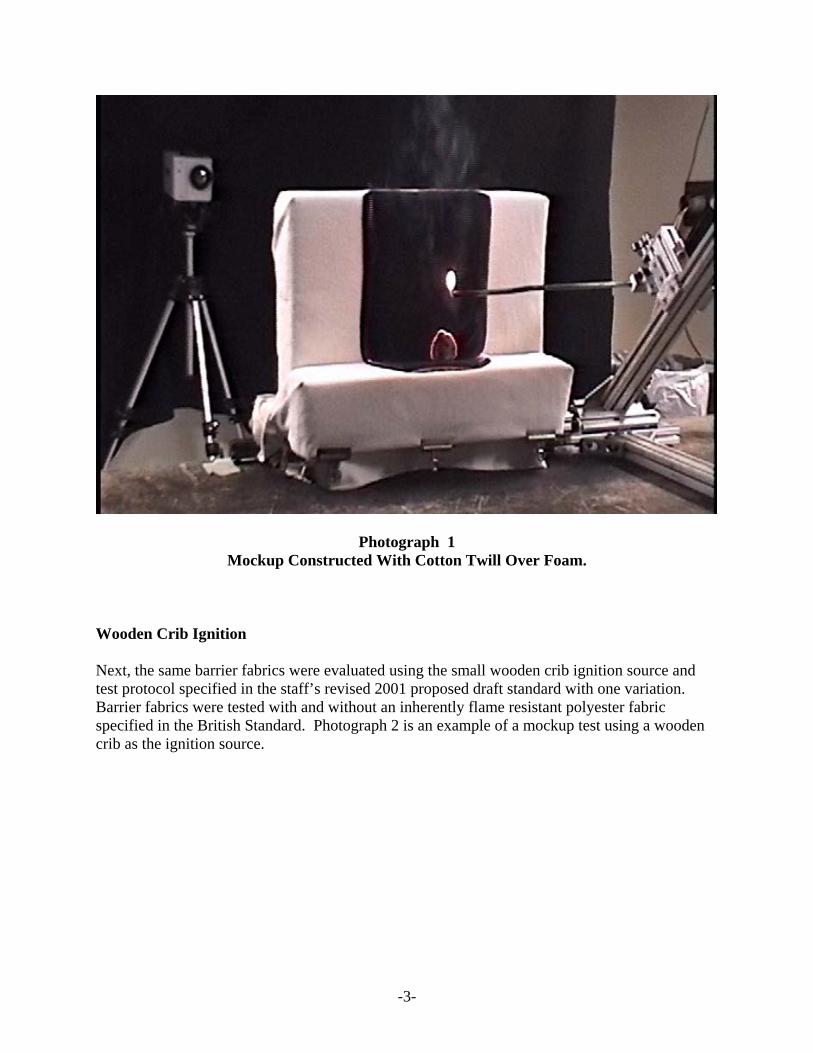
E - 100% aramid, 3.0 oz/yd2 M - melamine/aramid blend, 4.5 oz/yd2 F - melamine/aramid blend, 1.5 oz/yd2 N - melamine/aramid/ blend, 4.0 oz/yd2 G - melamine/aramid blend, 3.0 oz/yd2 As Table 1 shows, not all of the barriers were able to prevent ignition from occurring when combined with certain cover fabrics; especially the cellulosic/thermoplastic blend, the cotton twill and the acrylic/olefin blend fabrics. These cover fabrics appear to be particularly problematic in that when combined with certain barrier fabrics, ignitions to the mockups occur. Photograph 1 shows an example of a mockup test with burning cover fabric. _______________________ 3 Memorandum to Dale Ray, Project Manager, Upholstered Furniture, from L. Fansler, LS, Exploratory Tests of Barrier Materials, October 25, 2004.
-3-
Photograph 1 Mockup Constructed With Cotton Twill Over Foam.
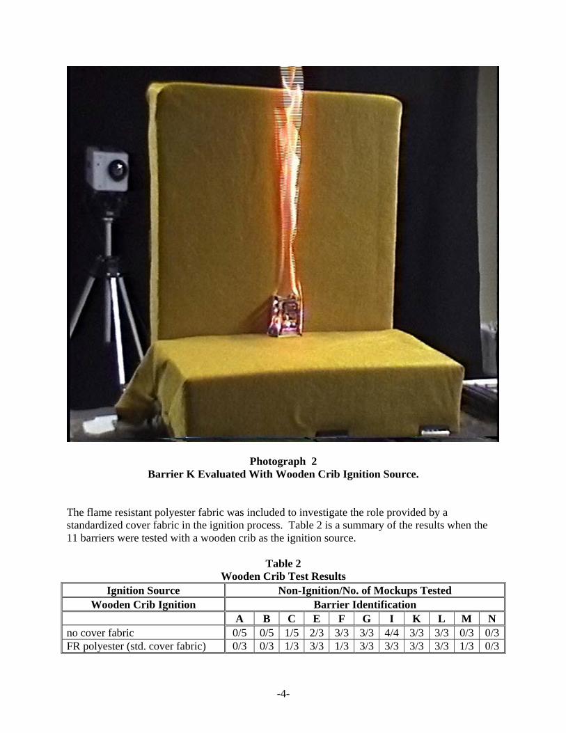
Wooden Crib Ignition Next, the same barrier fabrics were evaluated using the small wooden crib ignition source and test protocol specified in the staff’s revised 2001 proposed draft standard with one variation. Barrier fabrics were tested with and without an inherently flame resistant polyester fabric specified in the British Standard. Photograph 2 is an example of a mockup test using a wooden crib as the ignition source.
-4-
Photograph 2 Barrier K Evaluated With Wooden Crib Ignition Source.
The flame resistant polyester fabric was included to investigate the role provided by a standardized cover fabric in the ignition process. Table 2 is a summary of the results when the 11 barriers were tested with a wooden crib as the ignition source.
Table 2 Wooden Crib Test Results
Ignition Source Non-Ignition/No. of Mockups Tested Wooden Crib Ignition Barrier Identification
A B C E F G I K L M N no cover fabric 0/5 0/5 1/5 2/3 3/3 3/3 4/4 3/3 3/3 0/3 0/3FR polyester (std. cover fabric) 0/3 0/3 1/3 3/3 1/3 3/3 3/3 3/3 3/3 1/3 0/3
-5-
For the most part, the flame resistant polyester cover fabric did not influence results. Although differences were seen in Barriers E, F and M test results, the data is limited. Due to time constraints, LS staff decided to discontinue using the flame resistant polyester cover fabric in any further tests. As Table 2 indicates, some barrier fabrics performed better than others by preventing the foam from becoming involved in the ignition. In the tests without the standard flame resistant cover fabric, Barriers F, G, I, K, and L provided protection to the filling below. When the wooden crib results are compared to the burning cover fabric results, differences are evident. More ignitions occur when the burning cover fabric was the ignition source. This was especially apparent when comparing the results for Barriers F, G, I, K and L. These barriers would pass the draft crib protocol, but would fail when tested with several of the cover fabrics containing cellulosic fibers. Therefore, the wooden crib test protocol as drafted did not adequately challenge barrier fabrics. Staff believed that the wooden crib test protocol was not sufficient to evaluate fire-barriers, and an alternate ignition source that better mimics a burning cover fabric was needed. AFMA Burner Ignition In 2003 and early 2004, LS staff examined a third ignition source, a 12-inch burner designed by the American Furniture Manufacturers Association (AFMA) Flammability Committee. The burner has 22 ports spaced approximately 0.5 inch apart across the width of the burner with no port in the center. With a flow rate of 6.5 liters per minute (lpm) and an application time of 40 seconds, this burner appeared to provide an impressive flame source. Photograph 3 is a picture of the AMFA Burner.
-6-
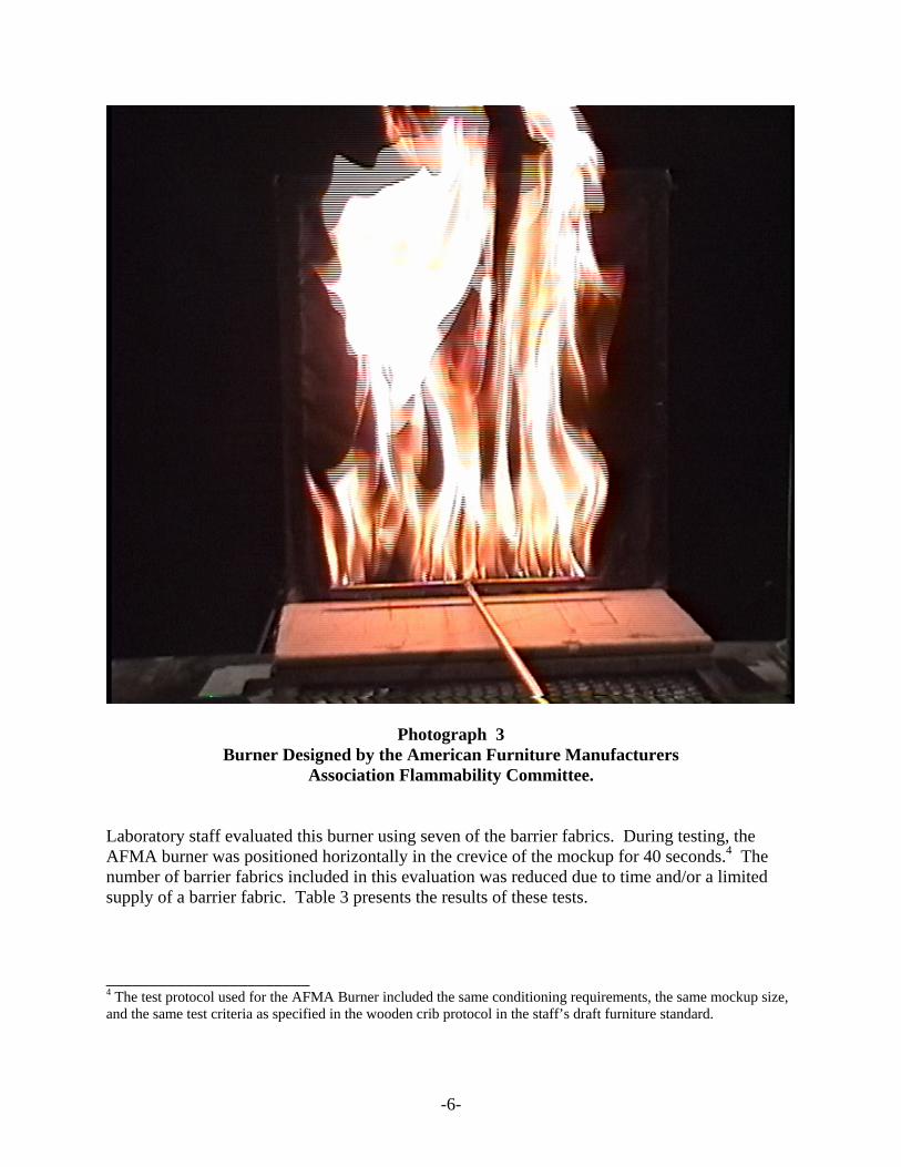
Photograph 3 Burner Designed by the American Furniture Manufacturers
Association Flammability Committee.
Laboratory staff evaluated this burner using seven of the barrier fabrics. During testing, the AFMA burner was positioned horizontally in the crevice of the mockup for 40 seconds.4 The number of barrier fabrics included in this evaluation was reduced due to time and/or a limited supply of a barrier fabric. Table 3 presents the results of these tests. _______________________ 4 The test protocol used for the AFMA Burner included the same conditioning requirements, the same mockup size, and the same test criteria as specified in the wooden crib protocol in the staff’s draft furniture standard.
-7-
Table 3 AFMA Burner Test Results
Ignition Source Non-Ignition/Number of Mockups Tested AFMA Burner Barrier Identification
C E F G I M N No cover fabric 2/3 3/3 3/3 3/3 3/3 1/3 1/3 As the results indicate, the AFMA Burner did not challenge the barrier fabrics. Four of the barrier fabrics, E, F, G and I, had no ignitions when exposed to the AFMA Burner. Three of those four, Barriers F, G and I, had foam ignition when combined with some of the cover fabrics. As Table 1 indicates, the cotton twill fabric produced the most ignitions among the cover fabrics when combined with Barriers F, G and I.
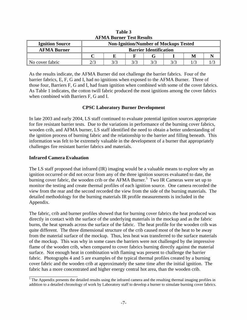
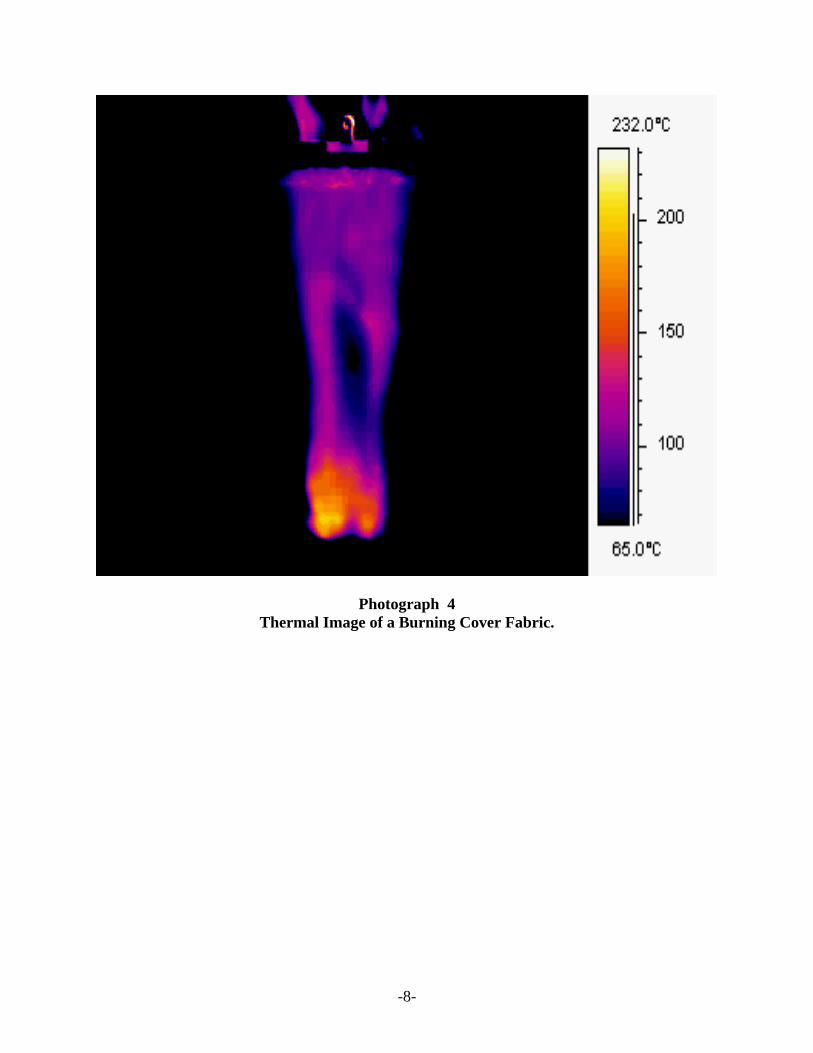
CPSC Laboratory Burner Development In late 2003 and early 2004, LS staff continued to evaluate potential ignition sources appropriate for fire resistant barrier tests. Due to the variations in performance of the burning cover fabrics, wooden crib, and AFMA burner, LS staff identified the need to obtain a better understanding of the ignition process of burning fabric and the relationship to the barrier and filling beneath. This information was felt to be extremely valuable in the development of a burner that appropriately challenges fire resistant barrier fabrics and materials. Infrared Camera Evaluation The LS staff proposed that infrared (IR) imaging would be a valuable means to explore why an ignition occurred or did not occur from any of the three ignition sources evaluated to date, the burning cover fabric, the wooden crib or the AFMA Burner.5 Two IR Cameras were set up to monitor the testing and create thermal profiles of each ignition source. One camera recorded the view from the rear and the second recorded the view from the side of the burning materials. The detailed methodology for the burning materials IR profile measurements is included in the Appendix. The fabric, crib and burner profiles showed that for burning cover fabrics the heat produced was directly in contact with the surface of the underlying materials in the mockup and as the fabric burns, the heat spreads across the surface of the fabric. The heat profile for the wooden crib was quite different. The three dimensional structure of the crib caused most of the heat to be away from the material surface of the mockup. Thus, less heat was transferred to the surface materials of the mockup. This was why in some cases the barriers were not challenged by the impressive flame of the wooden crib, when compared to cover fabrics burning directly against the material surface. Not enough heat in combination with flaming was present to challenge the barrier fabric. Photographs 4 and 5 are examples of the typical thermal profiles created by a burning cover fabric and the wooden crib at approximately the same time after the initial ignition. The fabric has a more concentrated and higher energy central hot area, than the wooden crib. ____________________ 5 The Appendix presents the detailed results using the infrared camera and the resulting thermal imaging profiles in addition to a detailed chronology of work by Laboratory staff to develop a burner to simulate burning cover fabrics.
-8-
Photograph 4 Thermal Image of a Burning Cover Fabric.
-9-
Photograph 5 Thermal Image of a Burning Wooden Crib.
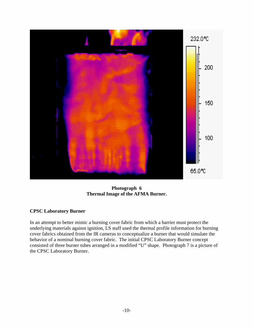
The AMFA Burner looked impressive with its 12-inch plus high flames, however examining the IR thermal profiles revealed too much unburned fuel resulting in a cooler flame due to incomplete combustion of the butane gas. Therefore, most of the heat energy rolled off the surface of the mockup and insufficient heat energy was transferred to the mockup surface to cause ignition. Photograph 6 is an example of the thermal profile created by the AFMA burner. While there was a broader thermal profile, the peak temperatures are generally lower and less concentrated than with the burning cover fabric.
-10-
Photograph 6 Thermal Image of the AFMA Burner.
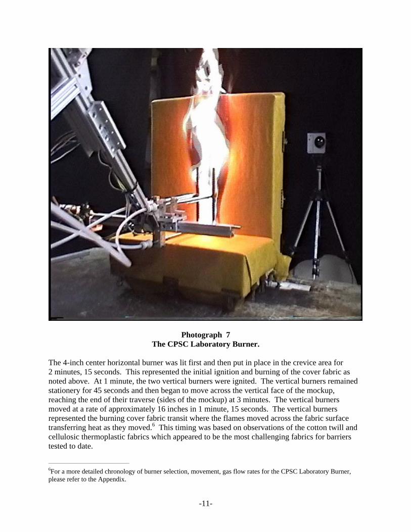
CPSC Laboratory Burner In an attempt to better mimic a burning cover fabric from which a barrier must protect the underlying materials against ignition, LS staff used the thermal profile information for burning cover fabrics obtained from the IR cameras to conceptualize a burner that would simulate the behavior of a nominal burning cover fabric. The initial CPSC Laboratory Burner concept consisted of three burner tubes arranged in a modified “U” shape. Photograph 7 is a picture of the CPSC Laboratory Burner.
-11-
Photograph 7 The CPSC Laboratory Burner.
The 4-inch center horizontal burner was lit first and then put in place in the crevice area for 2 minutes, 15 seconds. This represented the initial ignition and burning of the cover fabric as noted above. At 1 minute, the two vertical burners were ignited. The vertical burners remained stationery for 45 seconds and then began to move across the vertical face of the mockup, reaching the end of their traverse (sides of the mockup) at 3 minutes. The vertical burners moved at a rate of approximately 16 inches in 1 minute, 15 seconds. The vertical burners represented the burning cover fabric transit where the flames moved across the fabric surface transferring heat as they moved.6 This timing was based on observations of the cotton twill and cellulosic thermoplastic fabrics which appeared to be the most challenging fabrics for barriers tested to date. _____________________________________
6For a more detailed chronology of burner selection, movement, gas flow rates for the CPSC Laboratory Burner, please refer to the Appendix.
-12-
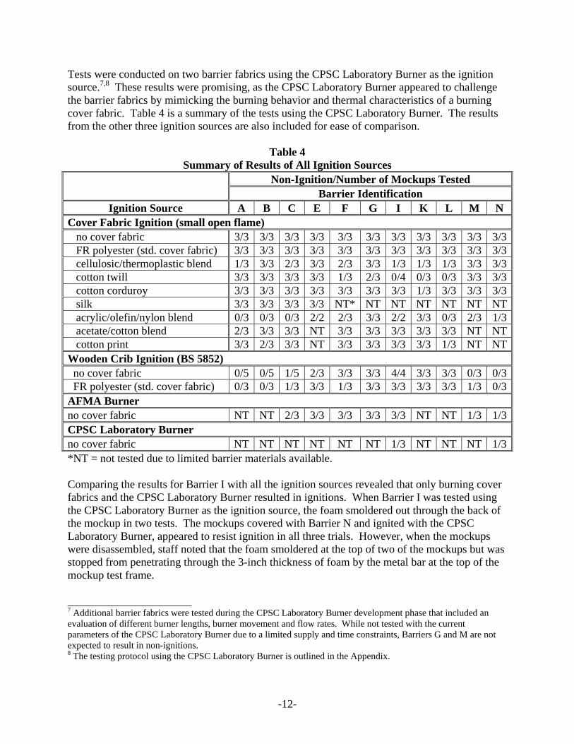
Tests were conducted on two barrier fabrics using the CPSC Laboratory Burner as the ignition source.7,8 These results were promising, as the CPSC Laboratory Burner appeared to challenge the barrier fabrics by mimicking the burning behavior and thermal characteristics of a burning cover fabric. Table 4 is a summary of the tests using the CPSC Laboratory Burner. The results from the other three ignition sources are also included for ease of comparison.
Table 4 Summary of Results of All Ignition Sources
Non-Ignition/Number of Mockups Tested Barrier Identification
Ignition Source A B C E F G I K L M N Cover Fabric Ignition (small open flame) no cover fabric 3/3 3/3 3/3 3/3 3/3 3/3 3/3 3/3 3/3 3/3 3/3 FR polyester (std. cover fabric) 3/3 3/3 3/3 3/3 3/3 3/3 3/3 3/3 3/3 3/3 3/3 cellulosic/thermoplastic blend 1/3 3/3 2/3 3/3 2/3 3/3 1/3 1/3 1/3 3/3 3/3 cotton twill 3/3 3/3 3/3 3/3 1/3 2/3 0/4 0/3 0/3 3/3 3/3 cotton corduroy 3/3 3/3 3/3 3/3 3/3 3/3 3/3 1/3 3/3 3/3 3/3 silk 3/3 3/3 3/3 3/3 NT* NT NT NT NT NT NT acrylic/olefin/nylon blend 0/3 0/3 0/3 2/2 2/3 3/3 2/2 3/3 0/3 2/3 1/3 acetate/cotton blend 2/3 3/3 3/3 NT 3/3 3/3 3/3 3/3 3/3 NT NT cotton print 3/3 2/3 3/3 NT 3/3 3/3 3/3 3/3 1/3 NT NTWooden Crib Ignition (BS 5852) no cover fabric 0/5 0/5 1/5 2/3 3/3 3/3 4/4 3/3 3/3 0/3 0/3 FR polyester (std. cover fabric) 0/3 0/3 1/3 3/3 1/3 3/3 3/3 3/3 3/3 1/3 0/3AFMA Burner no cover fabric NT NT 2/3 3/3 3/3 3/3 3/3 NT NT 1/3 1/3CPSC Laboratory Burner no cover fabric NT NT NT NT NT NT 1/3 NT NT NT 1/3*NT = not tested due to limited barrier materials available. Comparing the results for Barrier I with all the ignition sources revealed that only burning cover fabrics and the CPSC Laboratory Burner resulted in ignitions. When Barrier I was tested using the CPSC Laboratory Burner as the ignition source, the foam smoldered out through the back of the mockup in two tests. The mockups covered with Barrier N and ignited with the CPSC Laboratory Burner, appeared to resist ignition in all three trials. However, when the mockups were disassembled, staff noted that the foam smoldered at the top of two of the mockups but was stopped from penetrating through the 3-inch thickness of foam by the metal bar at the top of the mockup test frame. ______________________ 7 Additional barrier fabrics were tested during the CPSC Laboratory Burner development phase that included an evaluation of different burner lengths, burner movement and flow rates. While not tested with the current parameters of the CPSC Laboratory Burner due to a limited supply and time constraints, Barriers G and M are not expected to result in non-ignitions. 8 The testing protocol using the CPSC Laboratory Burner is outlined in the Appendix.
-13-
New Test Criteria The criteria for ignition of the Alternate Barrier Test in the staff’s 2001 Draft Standard for Small Open Flame Ignition is: Flaming Ignition
• escalated flaming combustion • test specimen is consumed • continued flaming beyond 10 minutes • debris caused floor fire
Smoldering Ignition
• escalated smoldering combustion • smolders to edge of specimen or the full thickness of the specimen • continued flaming, glowing or smoking after 60 minutes • evidence of charring within the filling more than 100 mm in any direction, apart from
Based on this current ignition source investigation work, LS staff recommends simplified test criteria for determining ignition for the Alternate Barrier Test. The simplified test criteria for determining ignition would include the following:
• barrier fabric or material is not breached (no splits, cracks, breaks, etc.) • foam is not flaming • no melt through or penetration to the back of the mockup frame
The revised criterion includes important factors in evaluating the performance of a barrier fabric or material. The barrier must remain intact to provide optimum protection to the filling below. The foam filling must not become involved in the ignition and there must not be any penetration through to the back of the mockup that sometimes occurs when the foam filling smolders behind an intact barrier. These criteria are straightforward and encompass the list of criteria in the staff’s 2001 draft standard. LS staff reviewed the cover fabric ignition test data and determined that the majority of ignitions fell into one of the recommended criteria. There was only one instance where the number of ignitions changed when the LS recommended criteria were applied. Also, LS staff notes that these can be very subjective criteria in how they are interpreted and that other more objective performance criteria may be more appropriate, such as mass loss over time during the test or mass loss of the foam substrate after a set test time. When Barrier I was tested with the burning cellulosic/thermoplastic blend cover fabric, the first trial self-extinguished, the second was still smoldering/glowing at 1 hour and in the third trial, the foam burned through to the back of the mockup. Applying the LS recommended criteria would result in two non-ignitions, reversing the second trial from an ignition classification to a non-ignition classification. Because ignition of the cover fabric is allowed to occur with the use of a barrier fabric, the intent is to provide additional time for escape not necessarily for self-extinguishment to occur. The different results between burning cover fabrics and gas burners that are intended to mimic the burning cover fabric may be a result of the effect of the cover fabric on the barrier. The cover fabric over the barrier results in a more compressed geometry for the barrier material, whereas the gas burner ignition source approach would not have that
-14-
constraint. The cover fabric-barrier-foam geometry is also more realistic of the material geometry that might be expected in a finished product. This effect may need to be explored in a subsequent study if a burner approach is to be considered further.
CONCLUSION The CPSC Laboratory Burner shows promise as a potential ignition source to evaluate barrier fabrics and related materials. By mimicking the burning behavior and thermal insult of a cover fabric, the CPSC Laboratory Burner was the only ignition source other than typical upholstery fabrics to cause an ignition when Barrier I was evaluated. A limited number of tests were completed because of time constraints and limited availability of barrier materials. Additional tests are needed with other barrier materials to confirm these results and to address the effect of a cover fabric on barrier performance versus unconstrained with the burner approach. Also, the test performance criteria should be evaluated to assess if criteria that are more objective can be established. Attachment: Appendix, November 2004.
-15-
November, 2004
APPENDIX A significant effort went into developing the CPSC Laboratory Burner. The following Appendix contains more thorough discussions of the work conducted towards an extensive examination of each ignition source, the wooden crib, the AFMA Burner and the CPSC Laboratory Burner. Laboratory tests included mockup testing and the use of Infrared (IR), Camera imaging to view the heat energy output of each of the ignition sources and the many variations to the test protocol evaluated during this study. Over 100 tests were conducted in the development of the CPSC Laboratory Burner. Many of the tests are discussed in the Appendix allowing the reader a view of the steps taken by, and thought processes of the CPSC Laboratory staff in developing a burner that realistically challenges fire blocking barrier fabrics by mimicking the burning behavior of a nominal burning cover fabric. Such a device could be used to evaluate any materials beneath the cover fabric and assess the system’s ability to resist sustained ignition or excess smoldering.
Evaluation of the Wooden Crib and AFMA Burner as Challenging Ignition Sources for Barrier Fabrics
Wooden Crib The small wooden crib is identified as the ignition source used to evaluate fire blocking barrier materials in the 2001 version of the staff’s draft upholstered furniture standard. The crib ignition source was taken from an existing British Standard.2 However, Laboratory staff was concerned that the crib as an ignition source did not adequately evaluate the fire blocking barrier fabrics. Test results indicated cases where barriers would pass the draft crib protocol but would fail when tested with several cover fabrics containing cellulosic fibers or blends. An 18 x 18 inch metal frame covered with stainless steel foil was used along with two IR Cameras to evaluate the burning behavior and heat output of the wooden crib. The IR Cameras captured the heat images given off from the burning wooden crib. The crib was ignited following the method in the staff’s draft standard; alcohol is added to the fabric covering the bottom of the crib and ignited with a match. The crib was placed in contact with the steel foil and allowed to burn until it collapsed and most of the embers were out. One IR camera was positioned behind the foil covered frame and the other to the side of the frame9 to capture the heat profiles of the burning wooden crib from two directions. The images indicated that the heat profile of the wooden crib is not always conducive to transferring the amount of heat energy required to challenge the barrier system. Because of the three dimensional structure of the crib, most of the heat is in front of the barrier, not in close enough contact with the barrier surface to be effective. Photograph 5 shows the thermal image of the burning wooden crib. ____________________ 9 The IR camera positioned to the side of the test frame is an older model camera. While Laboratory staff could view the side profile thermal images in real time, the same images captured on video tape were such poor quality that they are not included in this report.
-16-
AFMA Burner Laboratory staff also examined the heat output of the burner designed by the American Furniture Manufacturers Association (AFMA) Flammability Committee. The original goal of the Committee was to develop a test method using a gas burner instead of the wooden crib to qualify fire blocking barrier fabrics for use with the State of California’s revised Technical Bulletin 117.10 The Committee in conjunction with the California Bureau of Home Furnishings and Thermal Insulation wanted a burner that produced a wide flame front similar to a burning swatch of fabric as opposed to the wooden crib where the flame is confined to a small area. Laboratory staff discussed the burner concept and objectives with California Bureau Staff and met with a member of the AFMA Flammability Committee to further discuss the burner design, gas flow and flame impingement requirements and test protocol. In addition, the AFMA Burner was lent to the CPSC Laboratory to use as a model when constructing a similar burner for use at the CPSC Laboratory. The AFMA Burner is a 12-inch burner tube with 22–0.5-inch gas ports spaced evenly, 11 ports on each side of center. The test protocol establishes the flow rate of the AFMA burner at 6.5 lpm, which is half the flow of a larger burner specified in California Technical Bulletin 133,11 that is used to evaluate furniture for public occupancies. The same mockup specified in the wooden crib protocol is used with the AFMA Burner. The burner is positioned horizontally, 1 inch from the back of the mockup and 0.5 inches above the seat of the mockup for 40 seconds. The 40-second flame application time is one-half of the flame application time in California Technical Bulletin 133. The flames produced by the AFMA Burner impinge directly onto the back of the mockup reaching to the top of the mockup. Laboratory staff evaluated the AFMA Burner following this test protocol using seven barrier fabrics. Test results12 indicated that the AFMA Burner did not sufficiently challenge the barrier fabrics. Several of the barrier fabrics that ignited with other ignition sources such as the wooden crib and burning cover fabrics did not ignite when the AFMA Burner was applied to the barrier cover mockups. The foil-covered metal frame and the two IR Cameras were also used to examine the heat profile of the AFMA burner to better understand the observed performance. Although the AFMA burner produced impressive flames, the IR images indicated that the heat profile was too cool at the surface and not enough heat energy was being transferred to the surface of the mockup during testing. The IR images showed that the majority of heat energy was several inches away and above the test surface of the mockup. __________________ 10 State of California Department of Consumer Affairs, Bureau of Home Furnishings and Thermal Insulation, Technical Bulletin 117, “Requirements, Test Procedures and Apparatus for Testing the Flame Retardance of Resilient Filling Materials Used in Upholstered Furniture,” DRAFT 2/2002. 11 State of California Department of Consumer Affairs, Bureau of Home Furnishings and Thermal Insulation, Technical Bulletin 133, “Flammability Test Procedure for Seating Furniture for Use in Public Occupancies,” January 1991. 12 The test details are found in Table 3 of this memorandum.
-17-
To overcome the insufficient transfer of heat to the surface of the mockup by the AFMA burner concept, LS staff made changes to the protocol. First, the flame application time was increased from 40 seconds to 60 seconds. However, this did not improve the heat energy transfer to the mockup surface. The angle of the burner approach was also modified and the flow rate of gas reduced. The burner approach position was changed from horizontal to the crevice to angle at 45o to direct the flame into the crevice and the gas flow rate was cut in half. The flames, and therefore the heat, were now being directed downward into the crevice allowing the transfer of more heat energy directly to the mockup crevice. Thermal imaging showed an improvement in the amount of heat energy available, so mockup tests were conducted using Barriers G, I, and M. The results were disappointing as no ignitions were seen with the modified protocol, yet ignitions occurred when the same barrier fabrics were tested with cover fabrics. Laboratory staff was not satisfied with the overall performance of the AFMA Burner even with the modified test protocol, and agreed the AFMA Burner concept, while a very impressive flame source, would not adequately challenge fire blocking barrier fabrics.
Developmental Work in the Creation of the CPSC Laboratory Burner
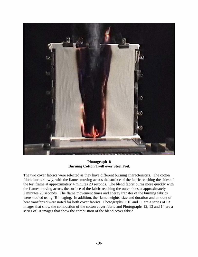
With knowledge of the AFMA Burner data and observations about heat energy transferred and preferring the concept of a gas burner over the wooden crib as the ignition source for fire blocking barrier evaluation, Laboratory staff decided to pursue designing and building a burner that more closely mimicked the burning behavior and heat transfer of burning cover fabrics. This process included an in-depth study of cover fabrics as ignition sources, refinement of the gas flow rates, and burner positioning and movement. Cover Fabric Study The study and understanding of the combustion of the cover fabric is important because by allowing the cover fabric to burn when a fire-blocking barrier is present, the burning cover fabric becomes the ignition source. Therefore, a better understanding of the role of a burning cover fabric was an important first step in the development of the CPSC Laboratory Burner. LS staff used IR cameras as imaging tools to study the cover fabric’s role in the ignition process. Two cover fabrics were studied. The two fabrics were a 100% cotton twill weave fabric (11.5 oz/yd2), and a rayon/polyester/cotton blend fabric (10.0 oz/yd2). These were selected based on prior testing since they provided the most challenging ignition sources for barriers tested to-date. The fabrics were mounted on a vertical 18 x 18 inch frame over a piece of stainless steel foil. The fabrics were ignited using small pieces of the same fabric soaked with alcohol placed at the bottom of the fabric covered foil panel. Photograph 8 shows the burning cotton twill cover fabric on the steel covered frame.
-18-
Photograph 8 Burning Cotton Twill over Steel Foil.
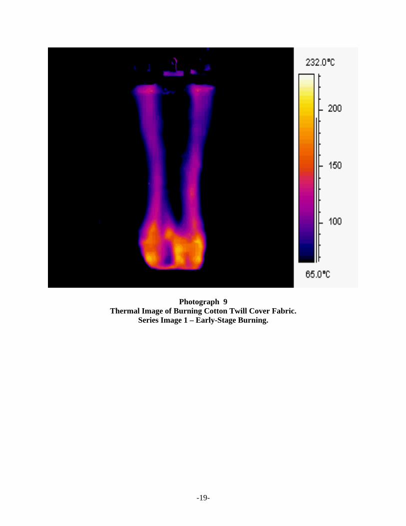
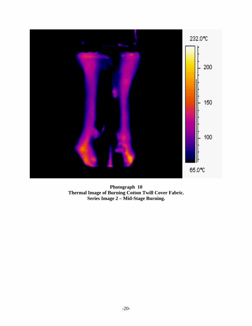
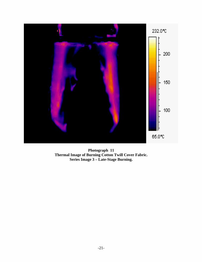
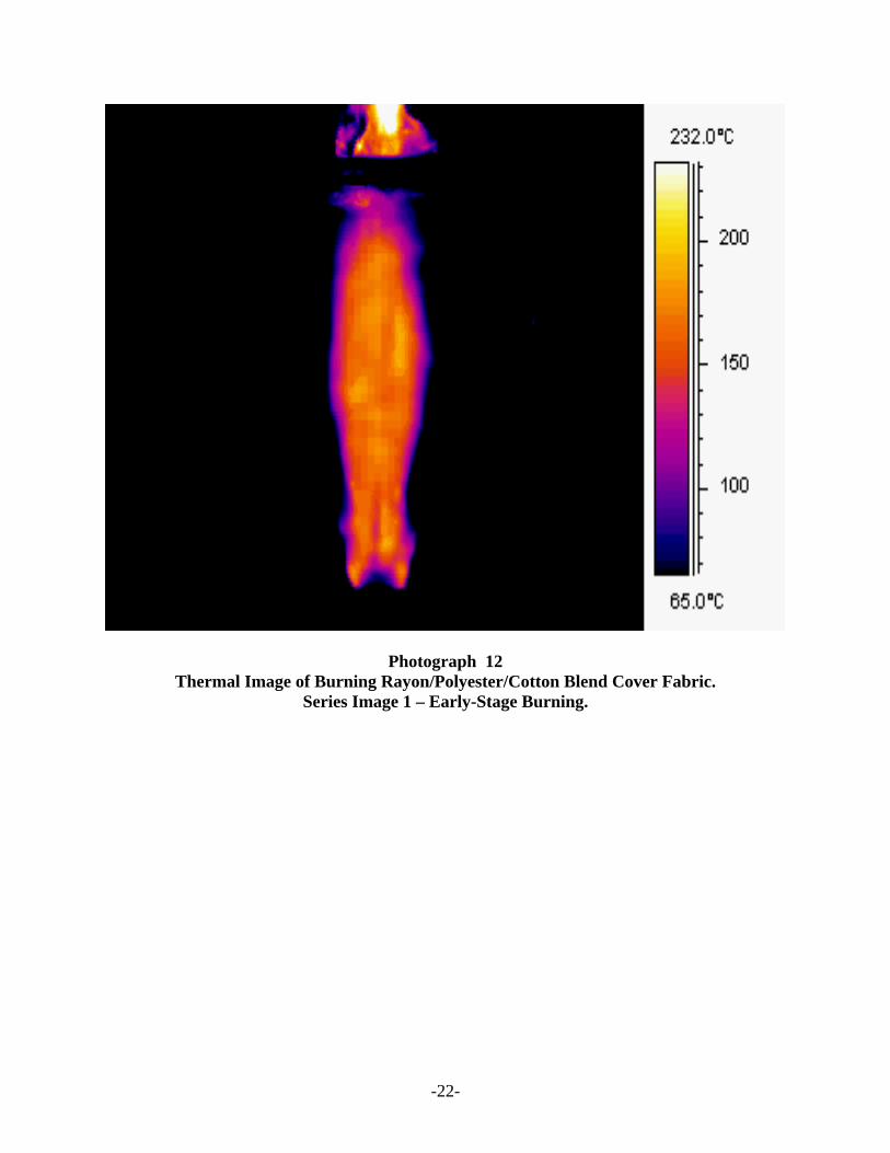
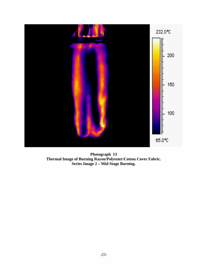
The two cover fabrics were selected as they have different burning characteristics. The cotton fabric burns slowly, with the flames moving across the surface of the fabric reaching the sides of the test frame at approximately 4 minutes 20 seconds. The blend fabric burns more quickly with the flames moving across the surface of the fabric reaching the outer sides at approximately 2 minutes 20 seconds. The flame movement times and energy transfer of the burning fabrics were studied using IR imaging. In addition, the flame heights, size and duration and amount of heat transferred were noted for both cover fabrics. Photographs 9, 10 and 11 are a series of IR images that show the combustion of the cotton cover fabric and Photographs 12, 13 and 14 are a series of IR images that show the combustion of the blend cover fabric.
-19-
Photograph 9 Thermal Image of Burning Cotton Twill Cover Fabric.
Series Image 1 – Early-Stage Burning.
-20-
Photograph 10 Thermal Image of Burning Cotton Twill Cover Fabric.
Series Image 2 – Mid-Stage Burning.
-21-
Photograph 11 Thermal Image of Burning Cotton Twill Cover Fabric.
Series Image 3 – Late-Stage Burning.
-22-
Photograph 12 Thermal Image of Burning Rayon/Polyester/Cotton Blend Cover Fabric.
Series Image 1 – Early-Stage Burning.
-23-
Photograph 13 Thermal Image of Burning Rayon/Polyester/Cotton Cover Fabric.
Series Image 2 – Mid-Stage Burning.
-24-
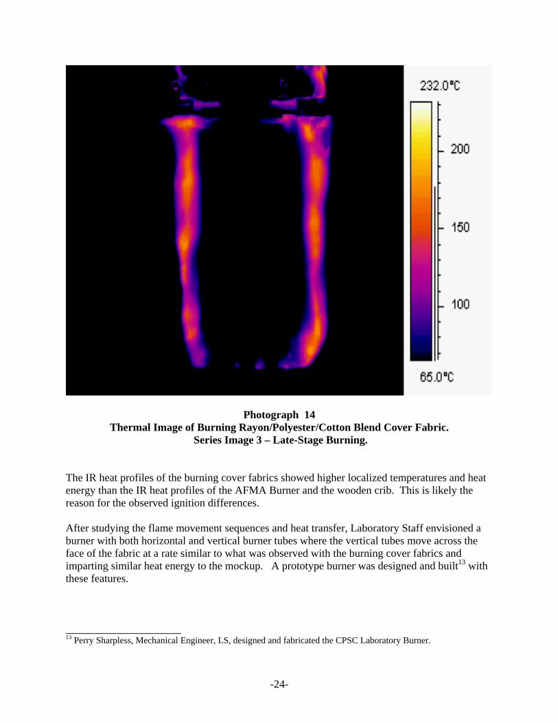
Photograph 14 Thermal Image of Burning Rayon/Polyester/Cotton Blend Cover Fabric.
Series Image 3 – Late-Stage Burning. The IR heat profiles of the burning cover fabrics showed higher localized temperatures and heat energy than the IR heat profiles of the AFMA Burner and the wooden crib. This is likely the reason for the observed ignition differences. After studying the flame movement sequences and heat transfer, Laboratory Staff envisioned a burner with both horizontal and vertical burner tubes where the vertical tubes move across the face of the fabric at a rate similar to what was observed with the burning cover fabrics and imparting similar heat energy to the mockup. A prototype burner was designed and built13 with these features. _____________________ 13 Perry Sharpless, Mechanical Engineer, LS, designed and fabricated the CPSC Laboratory Burner.
-25-
CPSC Laboratory Burner The concept behind the CPSC Laboratory Burner is the delivery of a flame for a specified time to the crevice of the fire blocking barrier mockup in a manner similar to a nominal cover fabric igniting and eventually burning across the surface of the mockup. The Burner is controlled by a series of electronic timers, solenoid valves, micro switches, and latching relays. A linear actuator provides the power to move burner tubes toward the mockup. The end of travel is detected by a micro switch that initiates the timing sequence. The burner tube movement and gas flow are controlled by timers. The burner tube movement across the face of the mockup occurs when a gear motor drives a single shaft with both left and right-hand threads. The shaft system is balanced to ensure uniform motion during movement. A limit switch detects the outer limit of the mockup and the gas flow is stopped. The CPSC Laboratory Burner has a burner tube positioned horizontally to the crevice delivering the initial insult of flames and heat energy. After a specified time, two vertical burner tubes mounted approximately 0.25 inches above the horizontal burner are ignited and begin moving across the face of the mockup. The horizontal burner is extinguished when the vertical burners pass the outer ends of the horizontal burner. The vertical burners continue moving until they reach the outer edges of the mockup. Experimental Variables In the course of the development of a test protocol to use with the CPSC Laboratory Burner, several variables were experimented with to optimize the Burner’s role in mimicking the burning behavior and thermal insult of a cover fabric. The variables included horizontal burner tube length, vertical burner tube movement, and pressure and gas flow to the burner tubes. Initially the horizontal burner tube was 3 inches in length with six gas ports spaced evenly across the length of the burner tube, with the gas ports angled downward toward the crevice. The horizontal burner was positioned 1 inch from the back of the mockup and 0.5 inches above the seat of the mockup. This horizontal burner length did not give results similar enough to burning cover fabrics. In some cases, barriers that did not previously ignite when exposed to a burning cover fabric were igniting when the 3-inch horizontal burner tube was part of the CPSC Laboratory Burner. The CPSC Laboratory Burner was refitted with a 4-inch horizontal burner and additional barrier tests were run. The 4-inch burner had two additional gas ports so the flames and heat energy were not as concentrated; more of the mockup surface was exposed during the initial ignition similar to the initial 2 minutes of typical burning fabrics. The 4-inch horizontal burner along with the two vertical burners more closely resembled the burning flame front on the cover fabrics. The timing sequence for burner movement was also varied. Initially after reviewing the IR and video images of burning cover fabrics, Laboratory staff programmed the CPSC Laboratory Burner so that the horizontal burner was lit as it approached the mockup with the vertical burners delayed by 40 seconds. At 60 seconds, the vertical burners started moving across the surface of the mockup, reaching the sides of the mockup at 140 seconds. The horizontal burner was programmed to go off at 80 seconds. This timing sequence proved too fast, moving the burners
-26-
across the surface of the mockup but not allowing the surface enough exposure to the heat energy and flames. Laboratory staff reviewed the IR and video images again and after trying a couple of different combinations settled on the following:
• Prior to Time zero - Horizontal Burner is lit. • Time zero - The burner assembly is driven into the crevice. • At 60 seconds – Vertical Burners are lit, • At 105 seconds - Vertical Burners begin moving, • At 135 seconds – Horizontal Burner goes out, • At 180 seconds – Vertical Burners reach side of mockup and go out.
This timing sequence is more realistic when compared with the combustion of the cotton twill and cellulosic/thermoplastic blend cover fabrics. Laboratory staff felt this timing sequence for the CPSC Laboratory Burner falls between the slow burning characteristics of the cotton twill and the faster burning blend fabrics. The gas tank pressure and gas flow rates were also varied until Laboratory staff was satisfied that they reflected the burning behavior of cover fabrics. The CPSC Laboratory Burner uses butane gas as the ignition source and two rotometers that measure the gas flow to the horizontal and vertical burners. Once the timing sequence of the burners was established, the initial gas flow rates were refined to produce flames and heat energy that reasonably represents the burning behavior of cover fabrics. The gas flow used for the horizontal and vertical burners follows:
• Horizontal Burner gas flow – 0.7 lpm • Vertical Burners gas flow – 2.4 lpm