Alignment and Stability of NSLS-II Magnet System* · PDF file ·...
46
Alignment and Stability of NSLS-II Magnet System* Animesh Jain Superconducting Magnet Division Brookhaven National Laboratory, Upton, NY 11973 for the NSLS-II Magnet Team 48 th ICFA Advanced Beam Dynamics Workshop on Future Light Sources (FLS2010) SLAC National Accelerator Laboratory, Menlo Park, California, 1-5 March, 2010 * Work supported by the U.S. Department of Energy under contract DE-AC02-98CH10886
Transcript of Alignment and Stability of NSLS-II Magnet System* · PDF file ·...
Alignment and Stabilityof NSLS-II Magnet System*
Animesh JainSuperconducting Magnet Division
Brookhaven National Laboratory, Upton, NY 11973for the NSLS-II Magnet Team
48th ICFA Advanced Beam Dynamics Workshop on Future Light Sources (FLS2010)
SLAC National Accelerator Laboratory, Menlo Park, California, 1-5 March, 2010
* Work supported by the U.S. Department of Energyunder contract DE-AC02-98CH10886
Alignment & Stability of NSLS-II Magnet System: Animesh Jain, BNLFLS2010: March 1-5, 2010
1
AcknowledgementsM. Anerella, R. Ceruti, J. Cintorino, T. Dilgen, S. Dimaiuta, L. Doom, G. Ganetis, P. He, R. Hubbard, P. Joshi, F. Karl, P. Kovach, F. Lincoln, W. Louie, A. Marone, J. Mc Caffrey,
D. Oldham, S. Ozaki, V. Ravindranath, P. Ribaudo,A. Sauerwald, S. Sharma, J. Skaritka, C. Spataro,
D. Sullivan, P. Wanderer, F. Willeke
D. Harder, G. Rakowsky, NSLSAlexander Temnykh, Cornell University
L. Rivkin, D. George, Swiss Light SourceDieter Einfeld, Montse Pont, ALBA
Alignment & Stability of NSLS-II Magnet System: Animesh Jain, BNLFLS2010: March 1-5, 2010
2
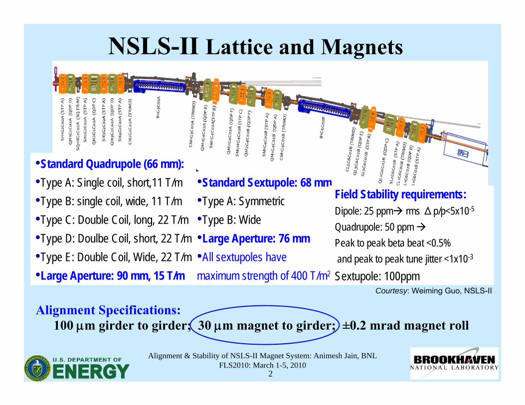
NSLS-II Lattice and Magnets
•Standard Quadrupole (66 mm):•Type A: Single coil, short,11 T/m•Type B: single coil, wide, 11 T/m•Type C: Double Coil, long, 22 T/m•Type D: Doulbe Coil, short, 22 T/m•Type E: Double Coil, Wide, 22 T/m•Large Aperture: 90 mm, 15 T/m
•Standard Sextupole: 68 mm•Type A: Symmetric•Type B: Wide•Large Aperture: 76 mm•All sextupoles have maximum strength of 400 T/m2
Field Stability requirements:Dipole: 25 ppm rms Δp/p<5x10-5
Quadrupole: 50 ppmPeak to peak beta beat <0.5%and peak to peak tune jitter <1x10⁻³
Sextupole: 100ppm
Alignment Specifications:100 μm girder to girder; 30 μm magnet to girder; ±0.2 mrad magnet roll
Courtesy: Weiming Guo, NSLS-II
Alignment & Stability of NSLS-II Magnet System: Animesh Jain, BNLFLS2010: March 1-5, 2010
3
Steps Involved in Alignment• Determine magnetic axis of all elements on a girder using
Vibrating Wire Technique, first developed at Cornell.• Move magnets on a girder to a common axis.• Secure magnets to the girder without disturbing the
alignment.• Verify alignment after securing the magnets.• Fully characterize the magnet and girder positions in
space.• Reproduce the magnet and girder positions during the
final installation in the machine.
Alignment & Stability of NSLS-II Magnet System: Animesh Jain, BNLFLS2010: March 1-5, 2010
4
Magnet Alignment R&D• Although the vibrating wire technique had been used in the
past for quadrupole measurements, very little work had been done in sextupoles.
• An R&D program was initiated to further develop the technique at BNL and demonstrate the required accuracy for both quadrupoles and sextupoles.
• Good measurement reproducibility has been achieved as a result of several improvements made over the course of this R&D program, which started in January, 2007.
• Work is still underway to study alignment stability and to adapt the measurements for a production environment.
Alignment & Stability of NSLS-II Magnet System: Animesh Jain, BNLFLS2010: March 1-5, 2010
5
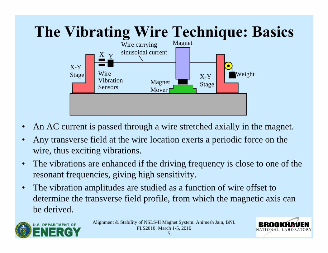
The Vibrating Wire Technique: Basics
• An AC current is passed through a wire stretched axially in the magnet.• Any transverse field at the wire location exerts a periodic force on the
wire, thus exciting vibrations.• The vibrations are enhanced if the driving frequency is close to one of the
resonant frequencies, giving high sensitivity. • The vibration amplitudes are studied as a function of wire offset to
determine the transverse field profile, from which the magnetic axis can be derived.
X-YStage
X-YStage
X Y
Weight
Wire carryingsinusoidal current
MagnetMover
Magnet
WireVibrationSensors
Alignment & Stability of NSLS-II Magnet System: Animesh Jain, BNLFLS2010: March 1-5, 2010
6
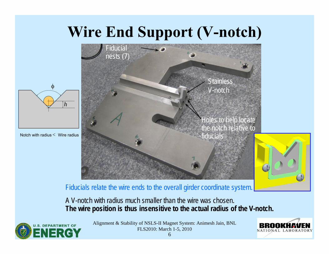
Wire End Support (V-notch)
Fiducials relate the wire ends to the overall girder coordinate system.
Stainless V-notch
Fiducialnests (7)
Holes to help locate the notch relative to fiducials
A V-notch with radius much smaller than the wire was chosen. The wire position is thus insensitive to the actual radius of the V-notch.
Notch with radius< Wire radius
φ
h
Alignment & Stability of NSLS-II Magnet System: Animesh Jain, BNLFLS2010: March 1-5, 2010
7
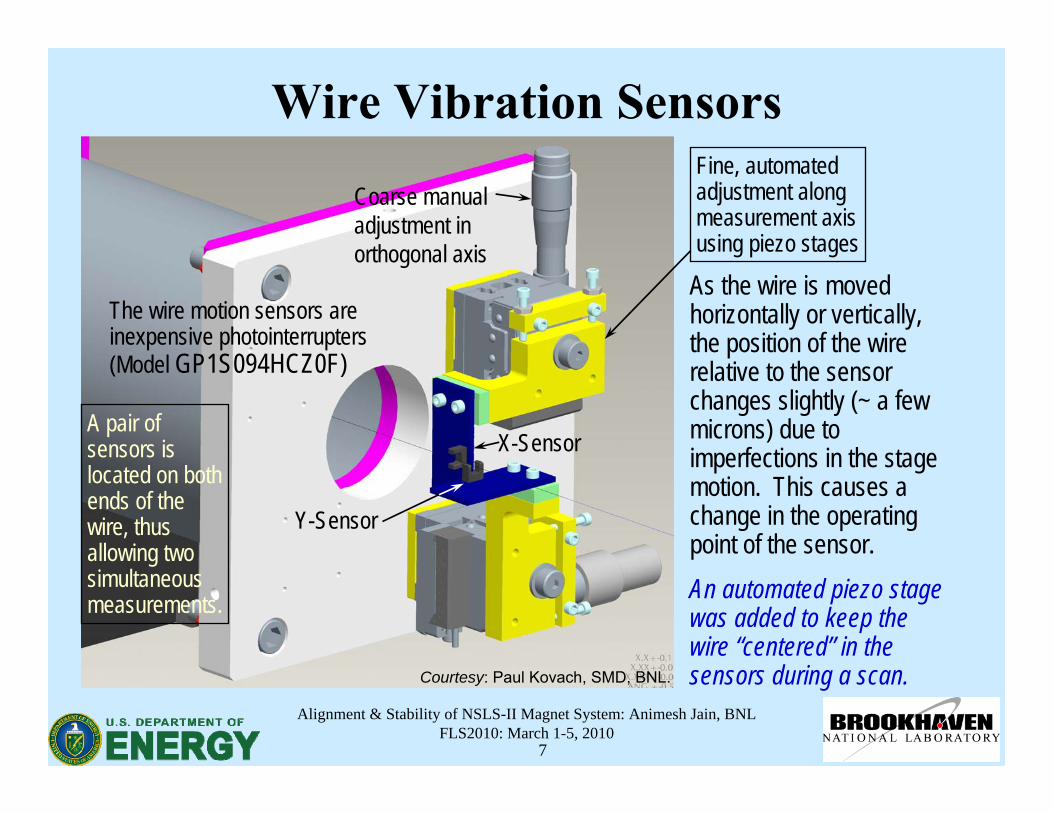
Wire Vibration Sensors
As the wire is moved horizontally or vertically, the position of the wire relative to the sensor changes slightly (~ a few microns) due to imperfections in the stage motion. This causes a change in the operating point of the sensor.An automated piezo stage was added to keep the wire “centered” in the sensors during a scan.
Coarse manual adjustment in orthogonal axis
X-Sensor
Fine, automated adjustment along measurement axis using piezo stages
Y-Sensor
The wire motion sensors are inexpensive photointerrupters(Model GP1S094HCZ0F)
A pair of sensors is located on both ends of the wire, thus allowing two simultaneous measurements.
Courtesy: Paul Kovach, SMD, BNL.
Alignment & Stability of NSLS-II Magnet System: Animesh Jain, BNLFLS2010: March 1-5, 2010
8
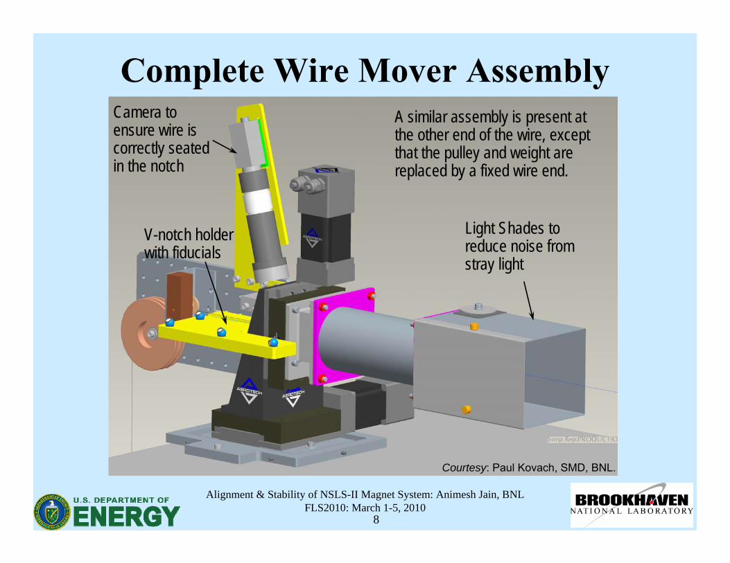
Complete Wire Mover AssemblyCamera to ensure wire is correctly seated in the notch
Light Shades to reduce noise from stray light
V-notch holder with fiducials
A similar assembly is present at the other end of the wire, except that the pulley and weight are replaced by a fixed wire end.
Courtesy: Paul Kovach, SMD, BNL.
Alignment & Stability of NSLS-II Magnet System: Animesh Jain, BNLFLS2010: March 1-5, 2010
9
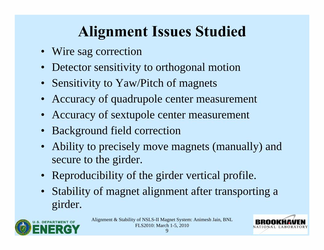
Alignment Issues Studied• Wire sag correction• Detector sensitivity to orthogonal motion• Sensitivity to Yaw/Pitch of magnets• Accuracy of quadrupole center measurement• Accuracy of sextupole center measurement• Background field correction• Ability to precisely move magnets (manually) and
secure to the girder.• Reproducibility of the girder vertical profile.• Stability of magnet alignment after transporting a
girder.
Alignment & Stability of NSLS-II Magnet System: Animesh Jain, BNLFLS2010: March 1-5, 2010
10
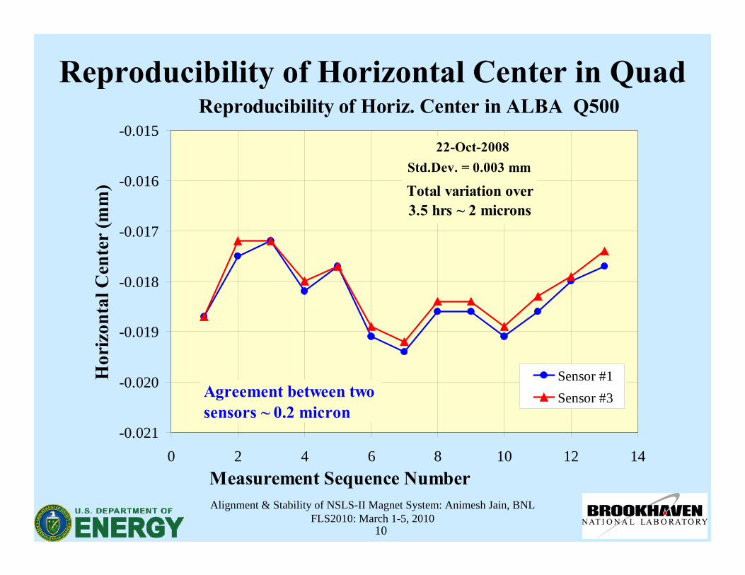
Reproducibility of Horizontal Center in QuadReproducibility of Horiz. Center in ALBA Q500
-0.021
-0.020
-0.019
-0.018
-0.017
-0.016
-0.015
0 2 4 6 8 10 12 14Measurement Sequence Number
Hor
izon
tal C
ente
r (m
m)
Sensor #1Sensor #3
Std.Dev. = 0.003 mm22-Oct-2008
Total variation over 3.5 hrs ~ 2 microns
Agreement between two sensors ~ 0.2 micron
Alignment & Stability of NSLS-II Magnet System: Animesh Jain, BNLFLS2010: March 1-5, 2010
11
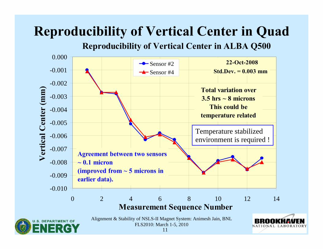
Reproducibility of Vertical Center in QuadReproducibility of Vertical Center in ALBA Q500
-0.010
-0.009
-0.008
-0.007
-0.006
-0.005
-0.004
-0.003
-0.002
-0.001
0.000
0 2 4 6 8 10 12 14Measurement Sequence Number
Ver
tical
Cen
ter
(mm
)
Sensor #2Sensor #4 Std.Dev. = 0.003 mm
22-Oct-2008
Total variation over3.5 hrs ~ 8 microns
This could be temperature related
Agreement between two sensors ~ 0.1 micron(improved from ~ 5 microns in earlier data).
Temperature stabilized environment is required !

Alignment & Stability of NSLS-II Magnet System: Animesh Jain, BNLFLS2010: March 1-5, 2010
12
Sextupole Measurements Using By and Bx
• Obtaining centers from By vs. x and By vs. y plots uses only one set of sensors, and requires quadratic fits.
• One could also use scans of Bx vs. x (or y) for various values of y(or x). These plots are expected to be linear with slopes proportional to offsets in y (or x) direction.
• Doing three such scans allows to obtain centers from both Bx and By data. With 2 sets of sensors, one gets four values of magnetic center.
• Yet another way is to use circular scans instead of linear scans.• 4 Methods × 2 Sensor sets = 8 independent measurements.
⎥⎥⎦
⎤
⎢⎢⎣
⎡ −−−= 2
20
20
3)()(
refy
RyyxxBB
⎥⎥⎦
⎤
⎢⎢⎣
⎡ −−= 2
003
))((2ref
xR
yyxxBB
Alignment & Stability of NSLS-II Magnet System: Animesh Jain, BNLFLS2010: March 1-5, 2010
13
-40
-20
0
20
40
60
80
100
120
-2.0 -1.5 -1.0 -0.5 0.0 0.5 1.0 1.5 2.0Wire Horizontal Position (mm)
By (a
rbitr
ary
units
)
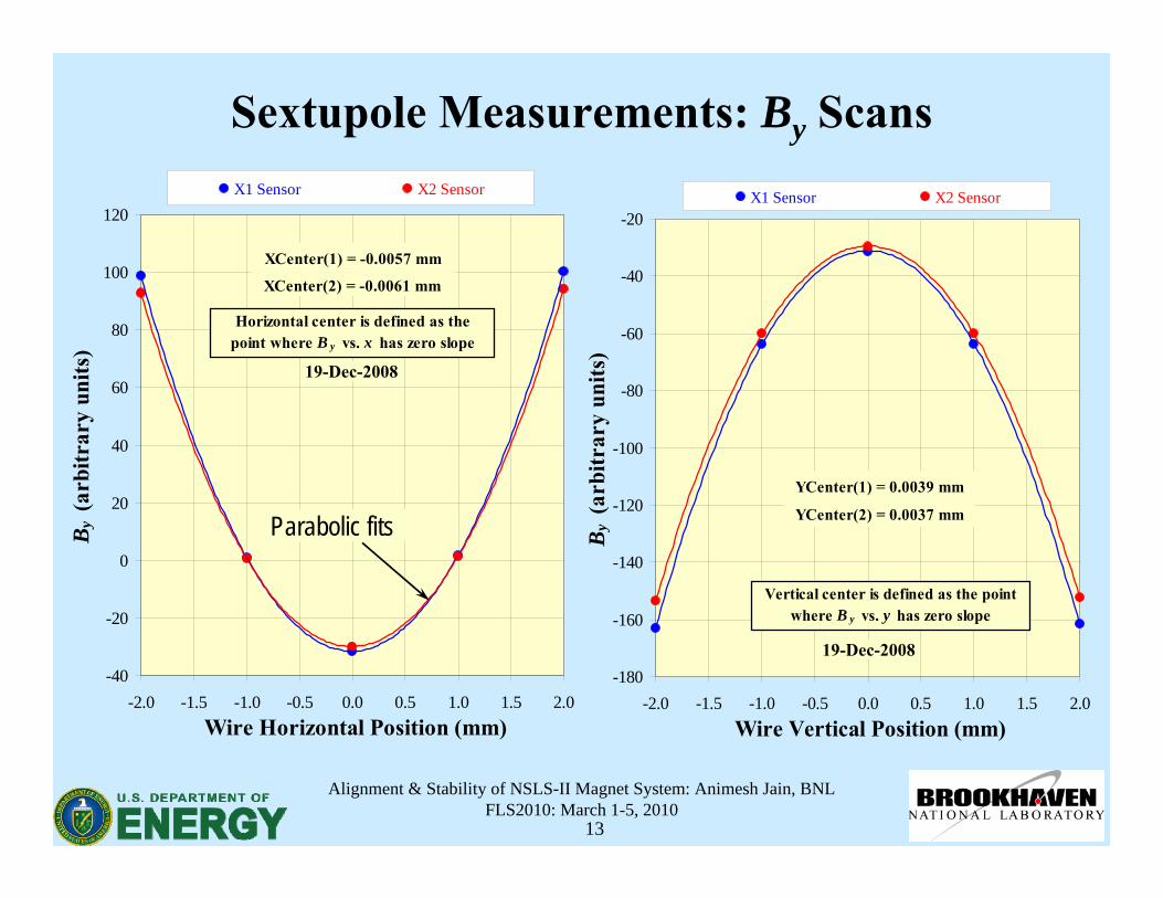
X1 Sensor X2 Sensor
Horizontal center is defined as the point where B y vs. x has zero slope
XCenter(1) = -0.0057 mm
XCenter(2) = -0.0061 mm
Sextupole Measurements: By Scans
Parabolic fits
-180
-160
-140
-120
-100
-80
-60
-40
-20
-2.0 -1.5 -1.0 -0.5 0.0 0.5 1.0 1.5 2.0Wire Vertical Position (mm)
By (a
rbitr
ary
units
)
X1 Sensor X2 Sensor
Vertical center is defined as the point where B y vs. y has zero slope
YCenter(1) = 0.0039 mm
YCenter(2) = 0.0037 mm
19-Dec-2008
19-Dec-2008
Alignment & Stability of NSLS-II Magnet System: Animesh Jain, BNLFLS2010: March 1-5, 2010
14
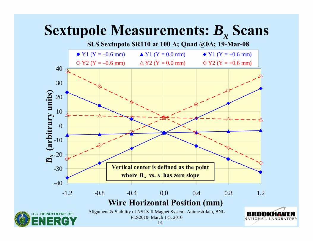
Sextupole Measurements: Bx ScansSLS Sextupole SR110 at 100 A; Quad @0A; 19-Mar-08
-40
-30
-20
-10
0
10
20
30
40
-1.2 -0.8 -0.4 0.0 0.4 0.8 1.2Wire Horizontal Position (mm)
Bx
(arb
itrar
y un
its)
Y1 (Y = –0.6 mm) Y1 (Y = 0.0 mm) Y1 (Y = +0.6 mm)Y2 (Y = –0.6 mm) Y2 (Y = 0.0 mm) Y2 (Y = +0.6 mm)
Vertical center is defined as the point where B x vs. x has zero slope
Alignment & Stability of NSLS-II Magnet System: Animesh Jain, BNLFLS2010: March 1-5, 2010
15
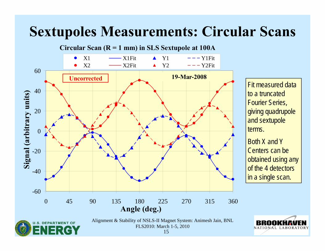
Sextupoles Measurements: Circular Scans
Fit measured data to a truncated Fourier Series, giving quadrupoleand sextupoleterms.Both X and Y Centers can be obtained using any of the 4 detectors in a single scan.
Circular Scan (R = 1 mm) in SLS Sextupole at 100A
-60
-40
-20
0
20
40
60
0 45 90 135 180 225 270 315 360Angle (deg.)
Sign
al (a
rbitr
ary
units
)
X1 X1Fit Y1 Y1FitX2 X2Fit Y2 Y2Fit
19-Mar-2008Uncorrected
Alignment & Stability of NSLS-II Magnet System: Animesh Jain, BNLFLS2010: March 1-5, 2010
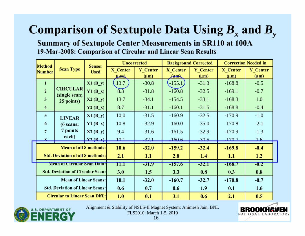
16
Summary of Sextupole Center Measurements in SR110 at 100A19-Mar-2008: Comparison of Circular and Linear Scan Results
X_Center(μm)
Y_Center(μm)
X_Center(μm)
Y_Center(μm)
X_Center(μm)
Y_Center(μm)
1 X1 (B_y) 13.7 -30.8 -155.1 -31.3 -168.8 -0.52 Y1 (B_x) 8.3 -31.8 -160.8 -32.5 -169.1 -0.73 X2 (B_y) 13.7 -34.1 -154.5 -33.1 -168.3 1.04 Y2 (B_x) 8.7 -31.1 -160.1 -31.5 -168.8 -0.45 X1 (B_y) 10.0 -31.5 -160.9 -32.5 -170.9 -1.06 Y1 (B_x) 10.8 -32.9 -160.0 -35.0 -170.8 -2.17 X2 (B_y) 9.4 -31.6 -161.5 -32.9 -170.9 -1.38 Y2 (B_x) 10.1 -32.1 -160.6 -30.5 -170.7 1.6
10.6 -32.0 -159.2 -32.4 -169.8 -0.42.1 1.1 2.8 1.4 1.1 1.211.1 -31.9 -157.6 -32.1 -168.7 -0.23.0 1.5 3.3 0.8 0.3 0.810.1 -32.0 -160.7 -32.7 -170.8 -0.70.6 0.7 0.6 1.9 0.1 1.61.0 0.1 3.1 0.6 2.1 0.5
Uncorrected Background Corrected Correction Needed inMethodNumber Scan Type Sensor
Used
CIRCULAR(single scan;
25 points)
LINEAR(6 scans;7 points
each)
Mean of all 8 methods:
Std. Deviation of all 8 methods:
Circular to Linear Scan Diff.:
Mean of Circular Scan Data:
Std. Deviation of Circular Scan:
Mean of Linear Scans:
Std. Deviation of Linear Scans:
Comparison of Sextupole Data Using Bx and By
Alignment & Stability of NSLS-II Magnet System: Animesh Jain, BNLFLS2010: March 1-5, 2010
17
Issue of Background Fields in Sextupole Meas.• There is a significant quadrupole background field from
quadrupole magnet(s) even when these are unpowered.
• Based on rotating coil data, the remnant integrated quadrupole field is ~0.02 T. This could amount to a change in horizontal center by hundreds of microns, depending on quad position and the mode used for sextupole measurements.
• The vertical center measurement is not affected because By(or Bx) is independent of y (or x) in a quadrupole field.
• Effectiveness of background correction has been tested by measuring a sextupole in the presence of a quadrupole which was either unpowered, or was powered at 2 A (apparent center shift of ~600 microns). Corrected center = ±5 microns.
Alignment & Stability of NSLS-II Magnet System: Animesh Jain, BNLFLS2010: March 1-5, 2010
18
Reproducing Girder Vertical Profile• The girder, if supported at the four corners only, has a sag of
about 150 microns.
• Based on studies done in a prototype girder, the vertical profile of the girder could vary by as much as ~20 microns simply as a result of handling.
• It is, therefore, essential to not only measure the magnet centers precisely, but also to have a precise means of characterizing and then reproducing the girder vertical profile during installation.
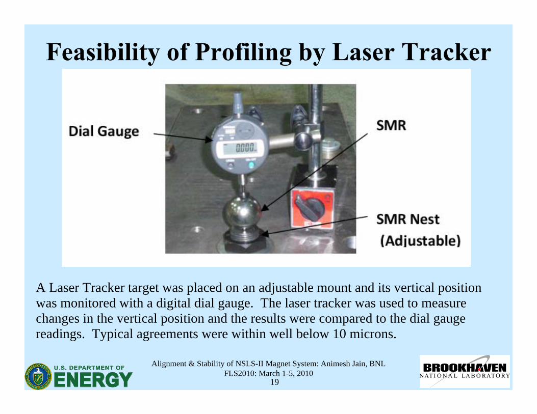
• It was demonstrated that the girder vertical profile can be measured to better than ~10 microns using multiple laser trackersetups in a temperature controlled chamber (< ±0.1 C).
Alignment & Stability of NSLS-II Magnet System: Animesh Jain, BNLFLS2010: March 1-5, 2010
19
Feasibility of Profiling by Laser Tracker
A Laser Tracker target was placed on an adjustable mount and its vertical position was monitored with a digital dial gauge. The laser tracker was used to measure changes in the vertical position and the results were compared to the dial gauge readings. Typical agreements were within well below 10 microns.
Alignment & Stability of NSLS-II Magnet System: Animesh Jain, BNLFLS2010: March 1-5, 2010
20
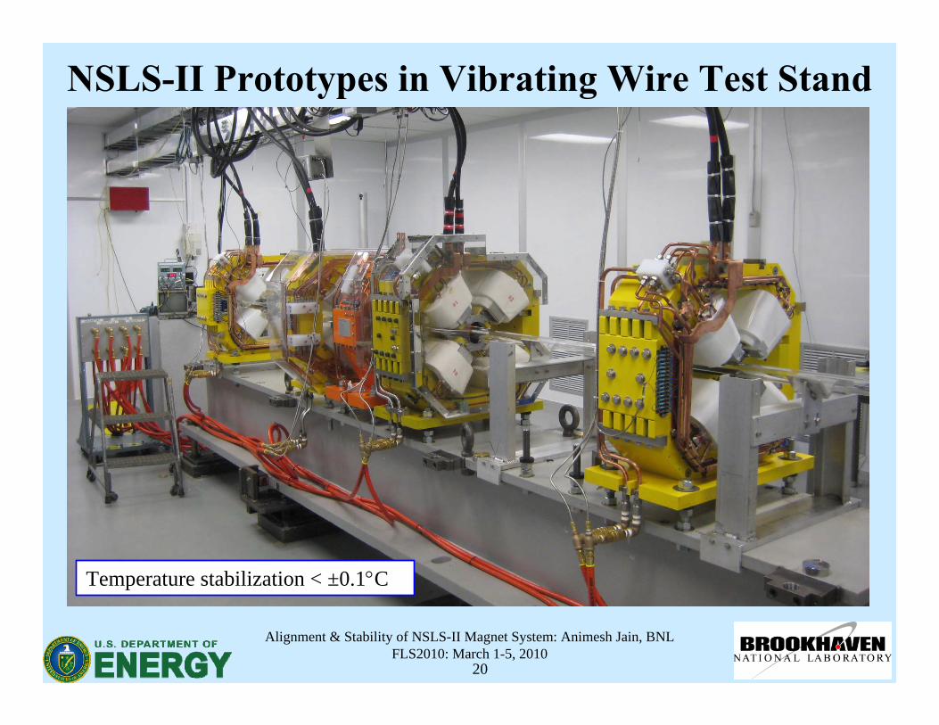
NSLS-II Prototypes in Vibrating Wire Test Stand
Temperature stabilization < ±0.1°C
Alignment & Stability of NSLS-II Magnet System: Animesh Jain, BNLFLS2010: March 1-5, 2010
21
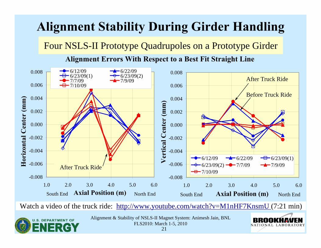
Alignment Stability During Girder Handling
Alignment Errors With Respect to a Best Fit Straight Line
-0.008
-0.006
-0.004
-0.002
0.000
0.002
0.004
0.006
0.008
1.0 2.0 3.0 4.0 5.0 6.0Axial Position (m)
Hor
izon
tal C
ente
r (m
m)
6/12/09 6/22/096/23/09(1) 6/23/09(2)7/7/09 7/9/097/10/09
North EndSouth End
After Truck Ride-0.008
-0.006
-0.004
-0.002
0.000
0.002
0.004
0.006
0.008
1.0 2.0 3.0 4.0 5.0 6.0
Axial Position (m)
Ver
tical
Cen
ter
(mm
) 6/12/09 6/22/09 6/23/09(1)6/23/09(2) 7/7/09 7/9/097/10/09
North EndSouth End
After Truck Ride
Before Truck Ride
Four NSLS-II Prototype Quadrupoles on a Prototype Girder
Watch a video of the truck ride: http://www.youtube.com/watch?v=M1nHF7KnsmU (7:21 min)
Alignment & Stability of NSLS-II Magnet System: Animesh Jain, BNLFLS2010: March 1-5, 2010
22
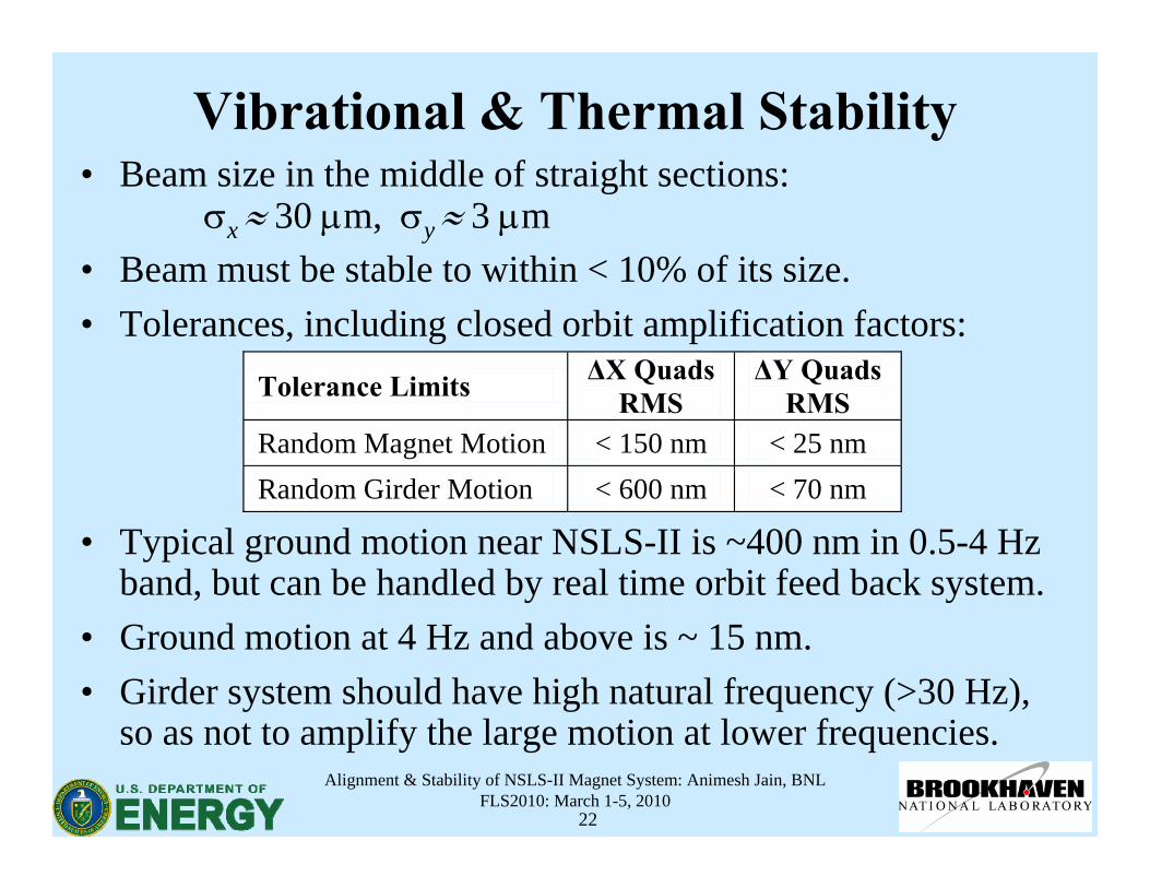
Vibrational & Thermal Stability• Beam size in the middle of straight sections:
σx ≈ 30 μm, σy≈ 3 μm• Beam must be stable to within < 10% of its size.• Tolerances, including closed orbit amplification factors:
• Typical ground motion near NSLS-II is ~400 nm in 0.5-4 Hz band, but can be handled by real time orbit feed back system.
• Ground motion at 4 Hz and above is ~ 15 nm.• Girder system should have high natural frequency (>30 Hz),
so as not to amplify the large motion at lower frequencies.
Tolerance Limits ΔX Quads RMS
ΔY Quads RMS
Random Magnet Motion < 150 nm < 25 nm Random Girder Motion < 600 nm < 70 nm
Alignment & Stability of NSLS-II Magnet System: Animesh Jain, BNLFLS2010: March 1-5, 2010
23
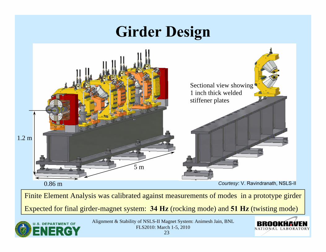
Girder Design
1.2 m
5 m
0.86 m
Sectional view showing 1 inch thick welded stiffener plates
Finite Element Analysis was calibrated against measurements of modes in a prototype girder
Expected for final girder-magnet system: 34 Hz (rocking mode) and 51 Hz (twisting mode)
Courtesy: V. Ravindranath, NSLS-II
Alignment & Stability of NSLS-II Magnet System: Animesh Jain, BNLFLS2010: March 1-5, 2010
24
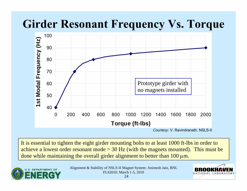
Girder Resonant Frequency Vs. Torque
It is essential to tighten the eight girder mounting bolts to at least 1000 ft-lbs in order to achieve a lowest order resonant mode > 30 Hz (with the magnets mounted). This must be done while maintaining the overall girder alignment to better than 100 μm.
40
50
60
70
80
90
100
0 200 400 600 800 1000 1200 1400 1600 1800 2000
Torque (ft-lbs)
1st M
odal
Fre
quen
cy (H
z)
Prototype girder with no magnets installed
Courtesy: V. Ravindranath, NSLS-II

Alignment & Stability of NSLS-II Magnet System: Animesh Jain, BNLFLS2010: March 1-5, 2010
25
Thermal Stability• Temperature changes in the cooling water (±0.05°C) and tunnel
temperature (±0.1°C) can induce motion of components.• Spatial temperature gradients can cause differential motion. • For sub-micron dynamic stability, temperature fluctuations in
the mechanical components should be within ±0.01°C.• The thermal inertia of the girder/magnets helps to limit the effect
of ambient temperature changes.• Measurements have been made of the girder temperature
changes in a controlled environment.• Work is in progress to design thermal deformation resistant
(visco-elastic) girder mounts, and to study effects of diurnal temperature cycles.
Alignment & Stability of NSLS-II Magnet System: Animesh Jain, BNLFLS2010: March 1-5, 2010
26
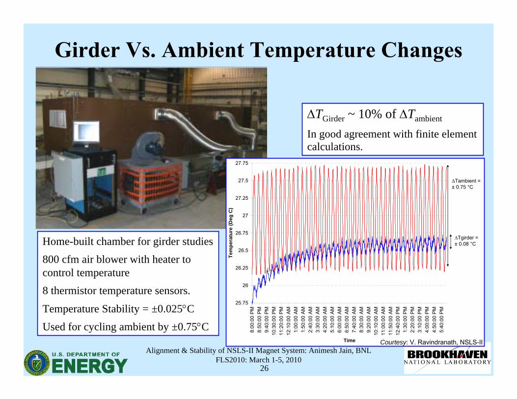
Girder Vs. Ambient Temperature Changes
25.75
26
26.25
26.5
26.75
27
27.25
27.5
27.75
8:00
:00
PM
8:50
:00
PM
9:40
:00
PM
10:3
0:00
PM
11:2
0:00
PM
12:1
0:00
AM
1:00
:00
AM
1:50
:00
AM
2:40
:00
AM
3:30
:00
AM
4:20
:00
AM
5:10
:00
AM
6:00
:00
AM
6:50
:00
AM
7:40
:00
AM
8:30
:00
AM
9:20
:00
AM
10:1
0:00
AM
11:0
0:00
AM
11:5
0:00
AM
12:4
0:00
PM
1:30
:00
PM
2:20
:00
PM
3:10
:00
PM
4:00
:00
PM
4:50
:00
PM
5:40
:00
PM
Time
Tem
pera
ture
(Deg
C)
∆Tambient = ± 0.75 °C
∆Tgirder = ± 0.08 °C Home-built chamber for girder studies
800 cfm air blower with heater to control temperature8 thermistor temperature sensors.
Temperature Stability = ±0.025°CUsed for cycling ambient by ±0.75°C
ΔTGirder ~ 10% of ΔTambient
In good agreement with finite element calculations.
Courtesy: V. Ravindranath, NSLS-II
Alignment & Stability of NSLS-II Magnet System: Animesh Jain, BNLFLS2010: March 1-5, 2010
27
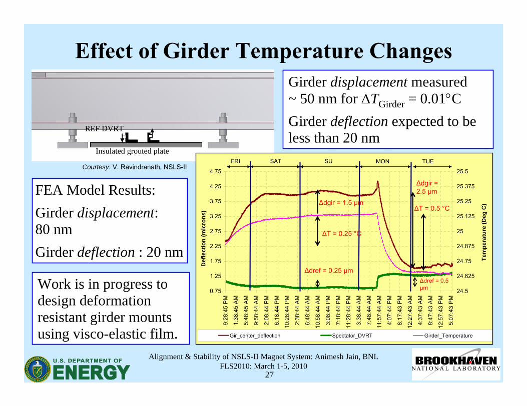
Effect of Girder Temperature Changes
REF DVRT
Insulated grouted plate
0.75
1.25
1.75
2.25
2.75
3.25
3.75
4.25
4.75
9:28
:45
PM
1:38
:45
AM
5:48
:45
AM
9:58
:44
AM
2:08
:44
PM
6:18
:44
PM
10:2
8:44
PM
2:38
:44
AM
6:48
:44
AM
10:5
8:44
AM
3:08
:44
PM
7:18
:44
PM
11:2
8:44
PM
3:38
:44
AM
7:48
:44
AM
11:5
7:44
AM
4:07
:44
PM
8:17
:43
PM
12:2
7:43
AM
4:37
:43
AM
8:47
:43
AM
12:5
7:43
PM
5:07
:43
PM
Tem
pera
ture
(Deg
C)
24.5
24.625
24.75
24.875
25
25.125
25.25
25.375
25.5
Def
lect
ion
(mic
rons
)
Gir_center_deflection Spectator_DVRT Girder_Temperature
FRI SAT SU MON TUE
∆T = 0.25 °C
∆dref = 0.25 μm
∆dgir = 1.5 μm
∆dgir = 2.5 μm
∆T = 0.5 °C
∆dref = 0.5 μm
Girder displacement measured~ 50 nm for ΔTGirder = 0.01°CGirder deflection expected to be less than 20 nm
Work is in progress to design deformation resistant girder mounts using visco-elastic film.
Courtesy: V. Ravindranath, NSLS-II
FEA Model Results:Girder displacement:80 nmGirder deflection : 20 nm
Alignment & Stability of NSLS-II Magnet System: Animesh Jain, BNLFLS2010: March 1-5, 2010
28
Conclusions• An extensive R&D program has been carried out to build a state-of-
the-art vibrating wire system, and to study various error sources.• Measurement procedures are developed to minimize the errors.• Excellent consistency (at sub-micron level) is routinely achieved
between data from two sets of sensors.• Absolute accuracy of < 5 μm, as judged by correlation with
mechanical motion, and consistency between four independent methods of measuring a sextupole, has been demonstrated.
• It has been shown that magnets can be secured to the girder while maintaining alignment within ~ 5-10 μm.
• The alignment of the magnets was shown to survive careful handling.• Vibrational stability requires careful control of resonant modes.• Thermal deformations need to be minimized even with ±0.1°C control
of the ambient temperature.
Alignment & Stability of NSLS-II Magnet System: Animesh Jain, BNLFLS2010: March 1-5, 2010
29
Thank You !

Alignment & Stability of NSLS-II Magnet System: Animesh Jain, BNLFLS2010: March 1-5, 2010
30
Supplemental Material
Alignment & Stability of NSLS-II Magnet System: Animesh Jain, BNLFLS2010: March 1-5, 2010
31
-0.8
-0.6
-0.4
-0.2
0
0.2
0.4
0.6
0.8
134 135 136 137 138 139 140 141Frequency (Hz)
<A_x
*I>
or
<A_y
*I>
A_x1 A_x1Calc A_y1 A_y1CalcA_x2 A_x2Calc A_y2 A_y2Calc
f x1=22.902 Hzf y1=22.899 Hzf x2=22.903 Hzf y2=22.900 Hz
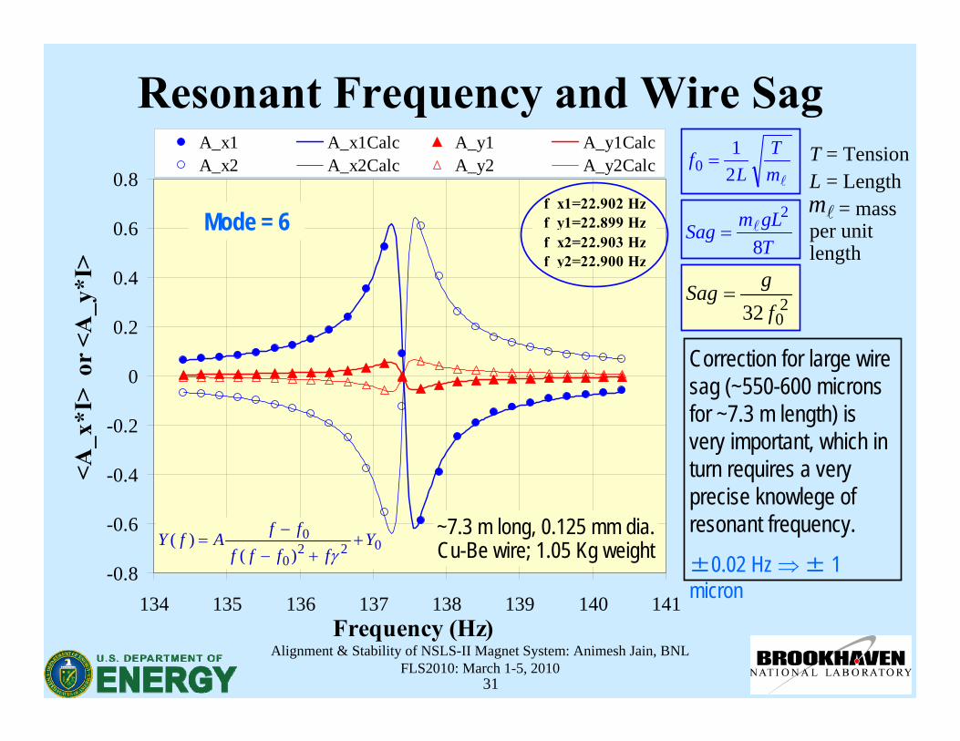
Resonant Frequency and Wire Sag
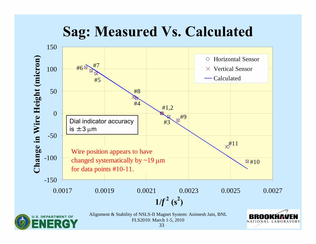
Correction for large wire sag (~550-600 microns for ~7.3 m length) is very important, which in turn requires a very precise knowlege of resonant frequency.±0.02 Hz ⇒± 1 micron
2032 f
gSag =
0220
0
)()( Y
ffffffAfY ++−
−=
γ
lmT
Lf
21
0 =
TgLmSag
8
2l=
~7.3 m long, 0.125 mm dia. Cu-Be wire; 1.05 Kg weight
T = TensionL = Length
= mass per unit length
lmMode = 6
Alignment & Stability of NSLS-II Magnet System: Animesh Jain, BNLFLS2010: March 1-5, 2010
32
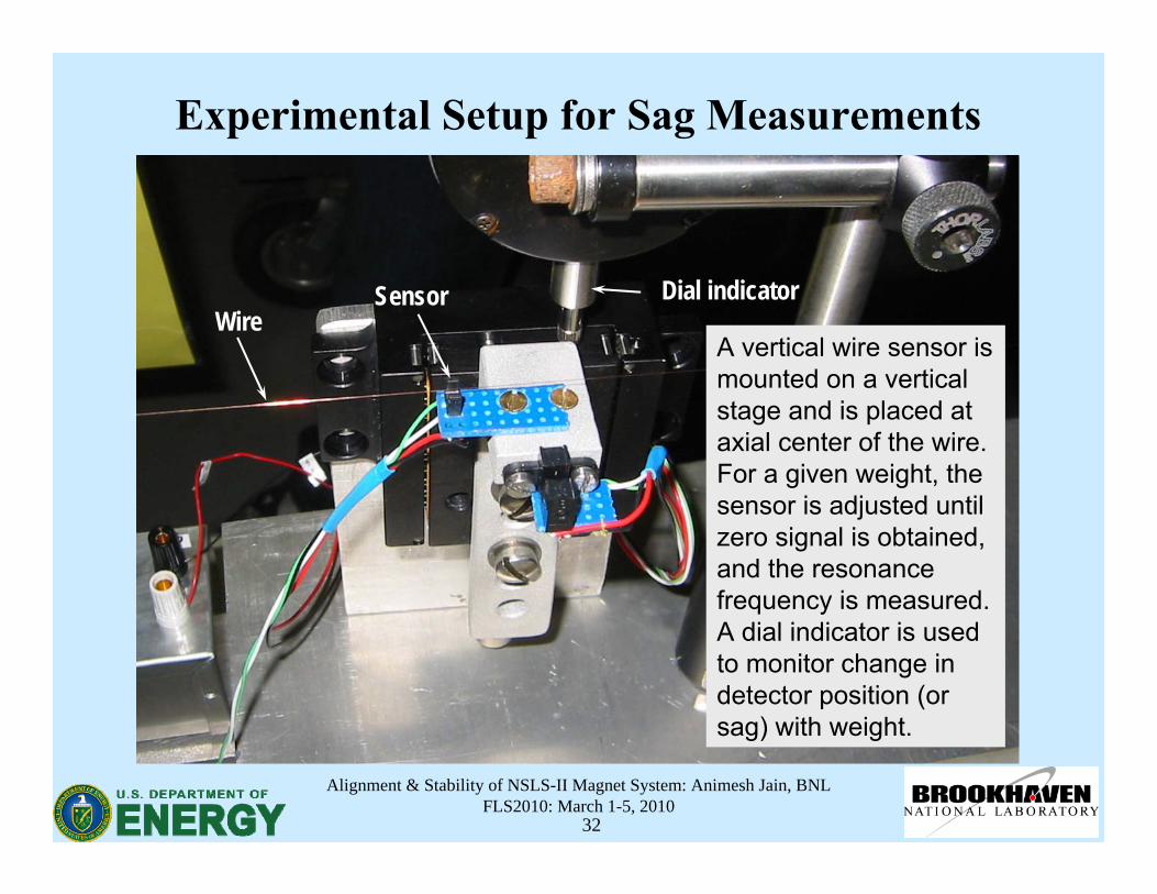
Experimental Setup for Sag Measurements
A vertical wire sensor is mounted on a vertical stage and is placed at axial center of the wire. For a given weight, the sensor is adjusted until zero signal is obtained, and the resonance frequency is measured. A dial indicator is used to monitor change in detector position (or sag) with weight.
Dial indicatorSensorWire
Alignment & Stability of NSLS-II Magnet System: Animesh Jain, BNLFLS2010: March 1-5, 2010
33
Sag: Measured Vs. Calculated
-150
-100
-50
0
50
100
150
0.0017 0.0019 0.0021 0.0023 0.0025 0.0027
1/f 2 (s2)
Cha
nge
in W
ire
Hei
ght (
mic
ron) Horizontal Sensor
Vertical SensorCalculated
Wire position appears to have changed systematically by ~19 μm for data points #10-11.
#1,2
#10
#3
#4
#5
#6 #7
#8
#9
#11
Dial indicator accuracyis ±3 μm
Alignment & Stability of NSLS-II Magnet System: Animesh Jain, BNLFLS2010: March 1-5, 2010
34
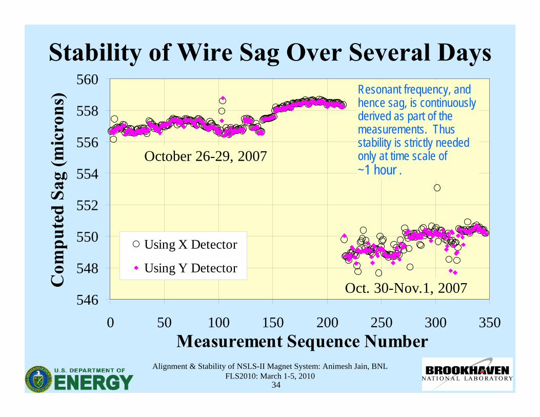
Stability of Wire Sag Over Several Days
SLS Quadrupole SLS Sextupole
546
548
550
552
554
556
558
560
0 50 100 150 200 250 300 350Measurement Sequence Number
Com
pute
d Sa
g (m
icro
ns)
Using X Detector
Using Y Detector
October 26-29, 2007
Oct. 30-Nov.1, 2007
Resonant frequency, and hence sag, is continuously derived as part of the measurements. Thus stability is strictly needed only at time scale of~1 hour .
Alignment & Stability of NSLS-II Magnet System: Animesh Jain, BNLFLS2010: March 1-5, 2010
35
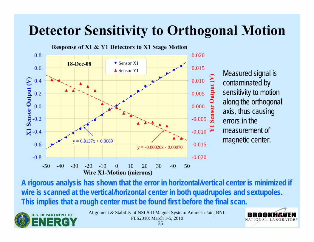
Detector Sensitivity to Orthogonal Motion
Measured signal is contaminated by sensitivity to motion along the orthogonal axis, thus causing errors in the measurement of magnetic center.
Response of X1 & Y1 Detectors to X1 Stage Motion
y = -0.00026x - 0.00070y = 0.0137x + 0.0089
-0.8
-0.6
-0.4
-0.2
0.0
0.2
0.4
0.6
0.8
-50 -40 -30 -20 -10 0 10 20 30 40 50Wire X1-Motion (microns)
X1
Sens
or O
utpu
t (V
)
-0.020
-0.015
-0.010
-0.005
0.000
0.005
0.010
0.015
0.020
Y1
Sens
or O
utpu
t (V
)
Sensor X1Sensor Y1
18-Dec-08
A rigorous analysis has shown that the error in horizontal/vertical center is minimized if wire is scanned at the vertical/horizontal center in both quadrupoles and sextupoles. This implies that a rough center must be found first before the final scan.
Alignment & Stability of NSLS-II Magnet System: Animesh Jain, BNLFLS2010: March 1-5, 2010
36
Resonant Mode to Use: Yaw/Pitch Sensitivity
• Should have a maxima near the axial center of the magnet being measured.
• Preferably even numbered modes should be used to avoid contribution from any axially uniform background fields (e.g. earth’s field).
• It may be impractical to find a mode with maxima exactly at the axial center for every magnet on the girder. This causes sensitivity to yaw and pitch.
• One should choose a mode that minimizes sensitivity to yaw and pitch without sacrificing signal strength.
Alignment & Stability of NSLS-II Magnet System: Animesh Jain, BNLFLS2010: March 1-5, 2010
37
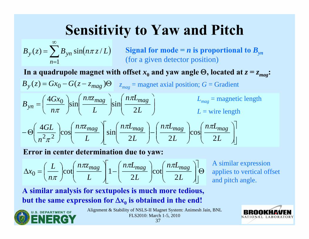
Sensitivity to Yaw and Pitch( )∑
∞
=
=1
/sin)(n
yny LznBzB π Signal for mode = n is proportional to Byn(for a given detector position)
In a quadrupole magnet with offset x0 and yaw angle Θ, located at z = zmag:Θ−−= )()( 0 magy zzGGxzB
⎥⎥⎦
⎤
⎢⎢⎣
⎡⎟⎟⎠
⎞⎜⎜⎝
⎛⎟⎟⎠
⎞⎜⎜⎝
⎛−⎟⎟
⎠
⎞⎜⎜⎝
⎛⎟⎟⎠
⎞⎜⎜⎝
⎛⎟⎠
⎞⎜⎝
⎛Θ−
⎟⎟⎠
⎞⎜⎜⎝
⎛⎟⎟⎠
⎞⎜⎜⎝
⎛⎟⎠⎞
⎜⎝⎛=
LLn
LLn
LLn
Lzn
nGL
LLn
Lzn
nGxB
magmagmagmag
magmagyn
2cos
22sincos4
2sinsin4
22
0
ππππ
π
πππ
Error in center determination due to yaw:
Θ⎥⎥⎦
⎤
⎢⎢⎣
⎡⎟⎟⎠
⎞⎜⎜⎝
⎛⎟⎟⎠
⎞⎜⎜⎝
⎛−⎟⎟
⎠
⎞⎜⎜⎝
⎛⎟⎠⎞
⎜⎝⎛=Δ
LLn
LLn
Lzn
nLx magmagmag
2cot
21cot0
ππππ
A similar analysis for sextupoles is much more tedious, but the same expression for Δx0 is obtained in the end!
A similar expression applies to vertical offset and pitch angle.
zmag = magnet axial position; G = Gradient
Lmag = magnetic length
L = wire length
Alignment & Stability of NSLS-II Magnet System: Animesh Jain, BNLFLS2010: March 1-5, 2010
38
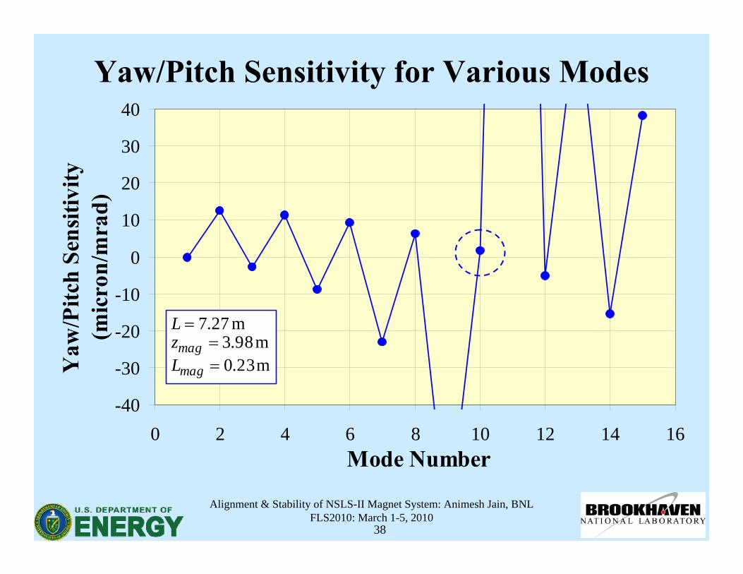
Yaw/Pitch Sensitivity for Various Modes
-40
-30
-20
-10
0
10
20
30
40
0 2 4 6 8 10 12 14 16Mode Number
Yaw
/Pitc
h Se
nsiti
vity
(m
icro
n/m
rad)
m 23.0m 98.3
m 27.7
==
=
mag
magLzL
Alignment & Stability of NSLS-II Magnet System: Animesh Jain, BNLFLS2010: March 1-5, 2010
39
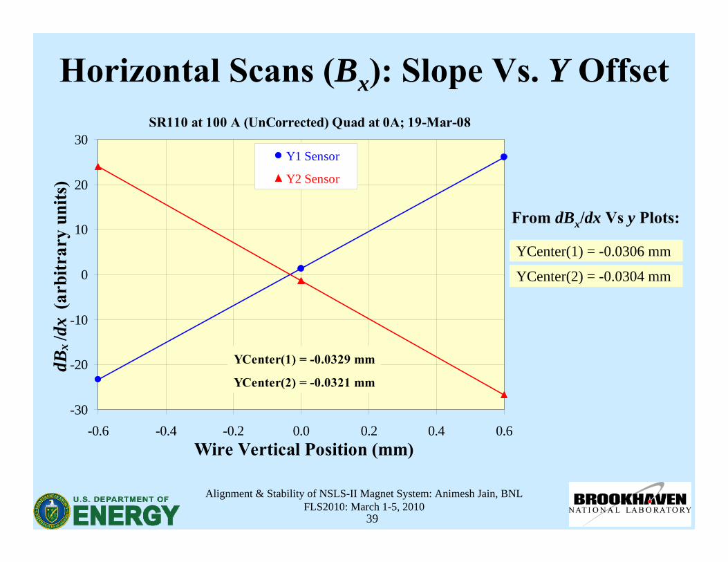
Horizontal Scans (Bx): Slope Vs. Y OffsetSR110 at 100 A (UnCorrected) Quad at 0A; 19-Mar-08
-30
-20
-10
0
10
20
30
-0.6 -0.4 -0.2 0.0 0.2 0.4 0.6Wire Vertical Position (mm)
dBx
/dx
(arb
itrar
y un
its)
Y1 Sensor
Y2 Sensor
YCenter(1) = -0.0329 mm
YCenter(2) = -0.0321 mm
YCenter(1) = -0.0306 mm
YCenter(2) = -0.0304 mm
From dBx/dx Vs y Plots:
Alignment & Stability of NSLS-II Magnet System: Animesh Jain, BNLFLS2010: March 1-5, 2010
40
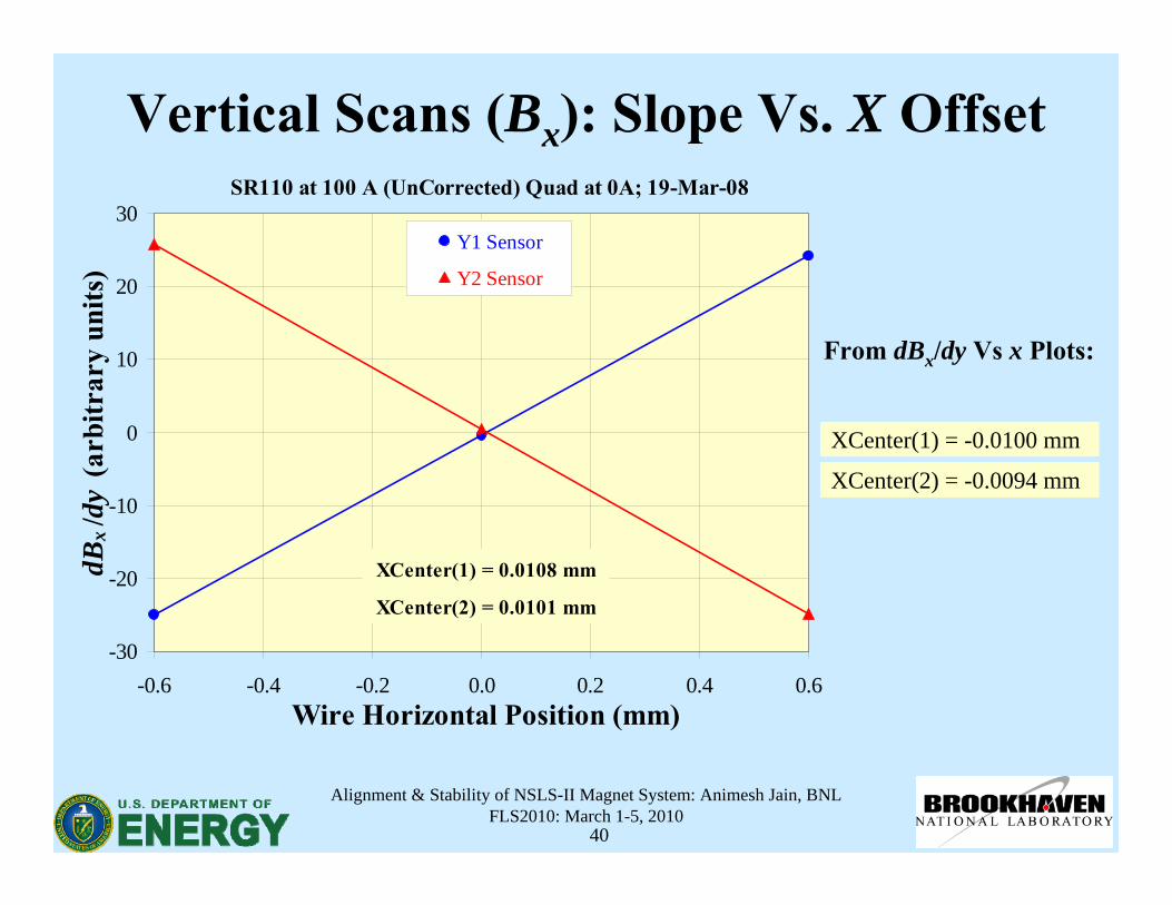
Vertical Scans (Bx): Slope Vs. X Offset
XCenter(1) = -0.0100 mm
XCenter(2) = -0.0094 mm
SR110 at 100 A (UnCorrected) Quad at 0A; 19-Mar-08
-30
-20
-10
0
10
20
30
-0.6 -0.4 -0.2 0.0 0.2 0.4 0.6Wire Horizontal Position (mm)
dBx
/dy
(arb
itrar
y un
its)
Y1 Sensor
Y2 Sensor
XCenter(1) = 0.0108 mm
XCenter(2) = 0.0101 mm
From dBx/dy Vs x Plots:
Alignment & Stability of NSLS-II Magnet System: Animesh Jain, BNLFLS2010: March 1-5, 2010
41
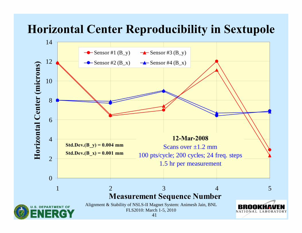
Horizontal Center Reproducibility in Sextupole
0
2
4
6
8
10
12
14
1 2 3 4 5Measurement Sequence Number
Hor
izon
tal C
ente
r (m
icro
ns)
Sensor #1 (B_y) Sensor #3 (B_y)
Sensor #2 (B_x) Sensor #4 (B_x)
12-Mar-2008Scans over ±1.2 mm
100 pts/cycle; 200 cycles; 24 freq. steps1.5 hr per measurement
Std.Dev.(B_y) = 0.004 mmStd.Dev.(B_x) = 0.001 mm
Alignment & Stability of NSLS-II Magnet System: Animesh Jain, BNLFLS2010: March 1-5, 2010
42
Procedure for Multipole Alignment on a Girder
• Install magnets on a girder, install vacuum chamber, and carry out a rough alignment using a laser system (horizontal and vertical offsets, pitch and yaw) and inclinometers (roll).
• Set up girder on a vibrating wire test stand in a temperature controlled environment (±0.1C), and wait for steady state.
• Tighten the 4 corner studs on the girder to several hundredft-lbs, secure center bolts and tighten to ~ 100 ft-lbs.
• Power one magnet at a time and measure the magnetic center using vibrating wire technique in the vibrating wire coordinate system, including appropriate correction for wire sag.
• Repeat for all magnets on the girder.
Alignment & Stability of NSLS-II Magnet System: Animesh Jain, BNLFLS2010: March 1-5, 2010
43
Procedure for Alignment on a Girder (contd.)• Force all displacement gauges to display the corresponding
measured magnet offsets.
• Lock the magnets in place, while monitoring the magnet positions to bring the magnets on-axis by making all gauges to read zero again.
• If required, carry out vibrating wire measurements again to confirm alignment.
• Survey the wire ends, and all girder and magnet fiducialsusing laser trackers. In particular, measure the girder vertical profile precisely (better than ±10 microns).
• Disconnect and remove the girder from the test stand.
Alignment & Stability of NSLS-II Magnet System: Animesh Jain, BNLFLS2010: March 1-5, 2010
44
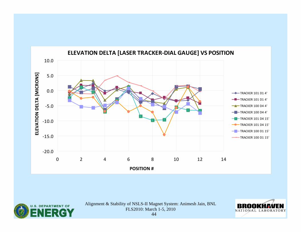
ELEVATION DELTA [LASER TRACKER‐DIAL GAUGE] VS POSITION
‐20.0
‐15.0
‐10.0
‐5.0
0.0
5.0
10.0
0 2 4 6 8 10 12 14
POSITION #
ELEV
ATION DELTA
[MICRONS]
TRACKER 101 D1 4'
TRACKER 101 D1 4'
TRACKER 100 D4 4'
TRACKER 100 D4 4'
TRACKER 101 D4 15'
TRACKER 101 D4 15'
TRACKER 100 D1 15'
TRACKER 100 D1 15'
Alignment & Stability of NSLS-II Magnet System: Animesh Jain, BNLFLS2010: March 1-5, 2010
45
Alignment Stability• Four NSLS-II prototype quadrupole magnets were mounted on a
prototype girder, and prealigned using a laser system.• The girder was installed in the temperature controlled room and the
magnets were hooked up to power and water supplies.• The magnetic centers of all the magnets were measured, and all the
remaining steps in the alignment process outlined earlier were carried out.
• The girder was then removed from the test bench, loaded on a truck, driven around the laboratory site, unloaded and reloaded on the truck, and then brought back to the test area.
• The girder was reinstalled, the girder vertical profile was reproduced using survey, and magnetic centers were measured again to see if the initial alignment of the magnets was maintained.


![Material Magnet [Compatibility Mode]](https://static.fdocument.org/doc/165x107/5885bc341a28ab1c198c4f13/material-magnet-compatibility-mode.jpg)