AL Alternating Current P.160. P.161 P.163 2πf = 50 π f = 25 X -1
72
AL Alternating Current P.160
-
Upload
sydney-weaver -
Category
Documents
-
view
222 -
download
0
Transcript of AL Alternating Current P.160. P.161 P.163 2πf = 50 π f = 25 X -1

AL Alternating Current
P.160
P.160
P.160
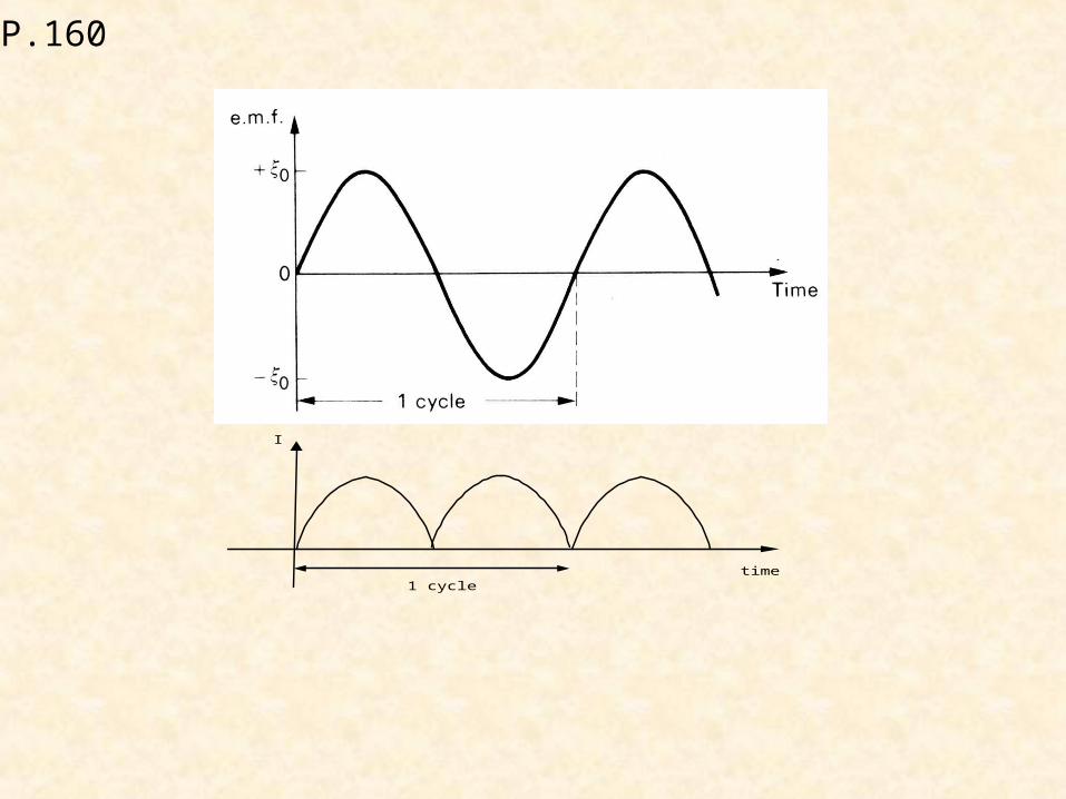
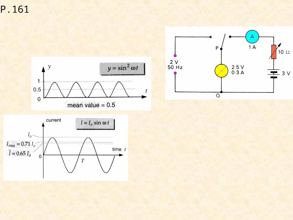
time
I
1 cycle
P.161
P.163
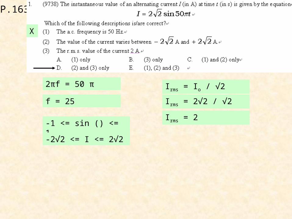
2πf = 50 π
f = 25
X
-1 <= sin () <= 1
-2√2 <= I <= 2√2
Irms = Io / √2
Irms = 2√2 / √2
Irms = 2
P.163
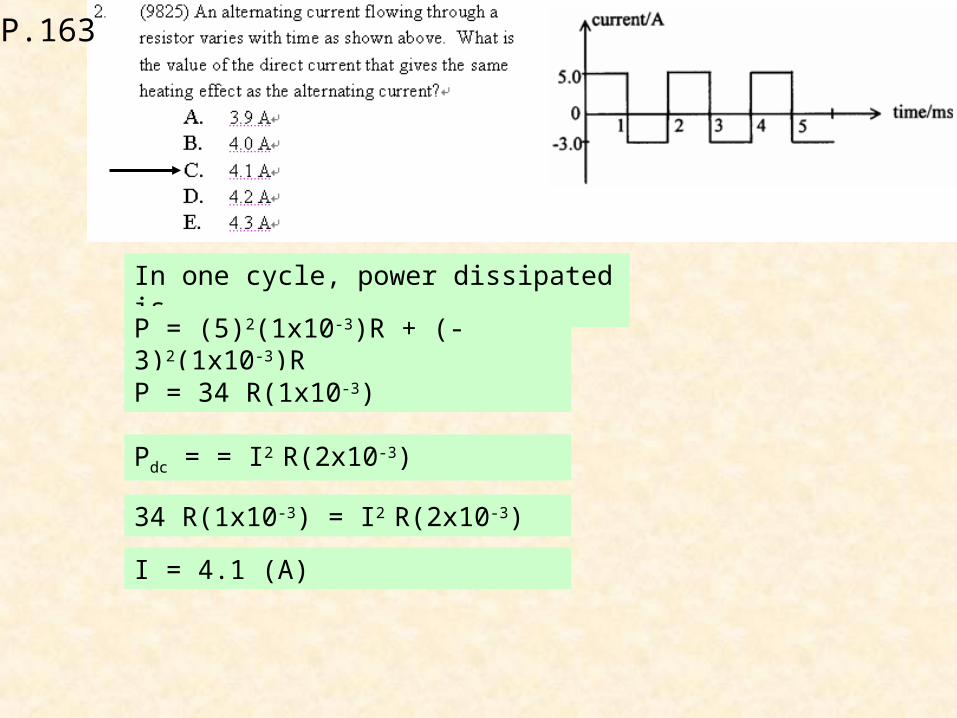
In one cycle, power dissipated is
P = (5)2(1x10⁻³)R + (-3)2(1x10⁻³)R
P = 34 R(1x10⁻³)
Pdc = = I2 R(2x10⁻³)
34 R(1x10⁻³) = I2 R(2x10⁻³)
I = 4.1 (A)
P.163
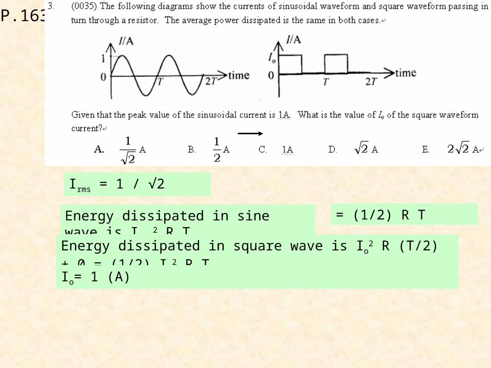
Irms = 1 / √2
Energy dissipated in sine wave is Irms2 R T = (1/2) R T
Energy dissipated in square wave is Io2 R (T/2) + 0 = (1/2) Io
2 R T
Io= 1 (A)
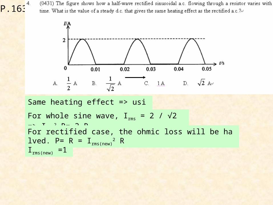
P.163
Same heating effect => using rms
For whole sine wave, Irms = 2 / √2 => Irms2 R= 2 R
For rectified case, the ohmic loss will be halved. P= R = Irms(new)2 R
Irms(new) =1
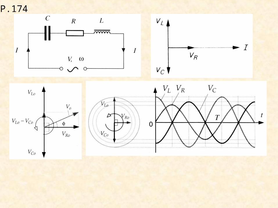
P.174
P.174

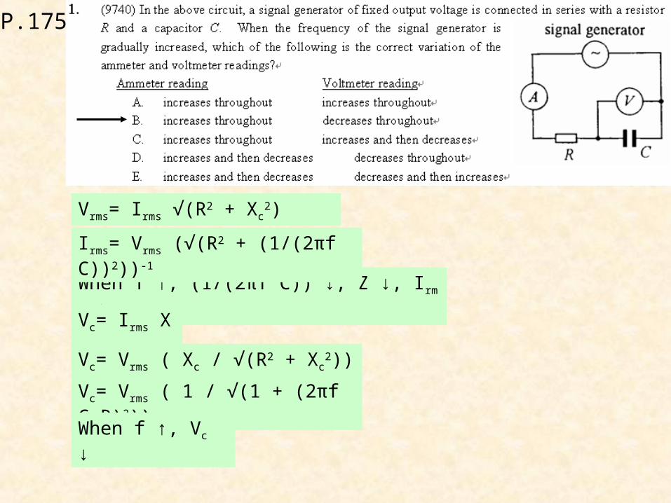
P.175
P.175
Vrms= Irms √(R2 + Xc2)
When f ↑, (1/(2πf C)) ↓, Z ↓, Irms ↑
Irms= Vrms (√(R2 + (1/(2πf C))2))-1
Vc= Irms Xc
Vc= Vrms ( Xc / √(R2 + Xc2))
Vc= Vrms ( 1 / √(1 + (2πf C R)2))
When f ↑, Vc ↓
P.175
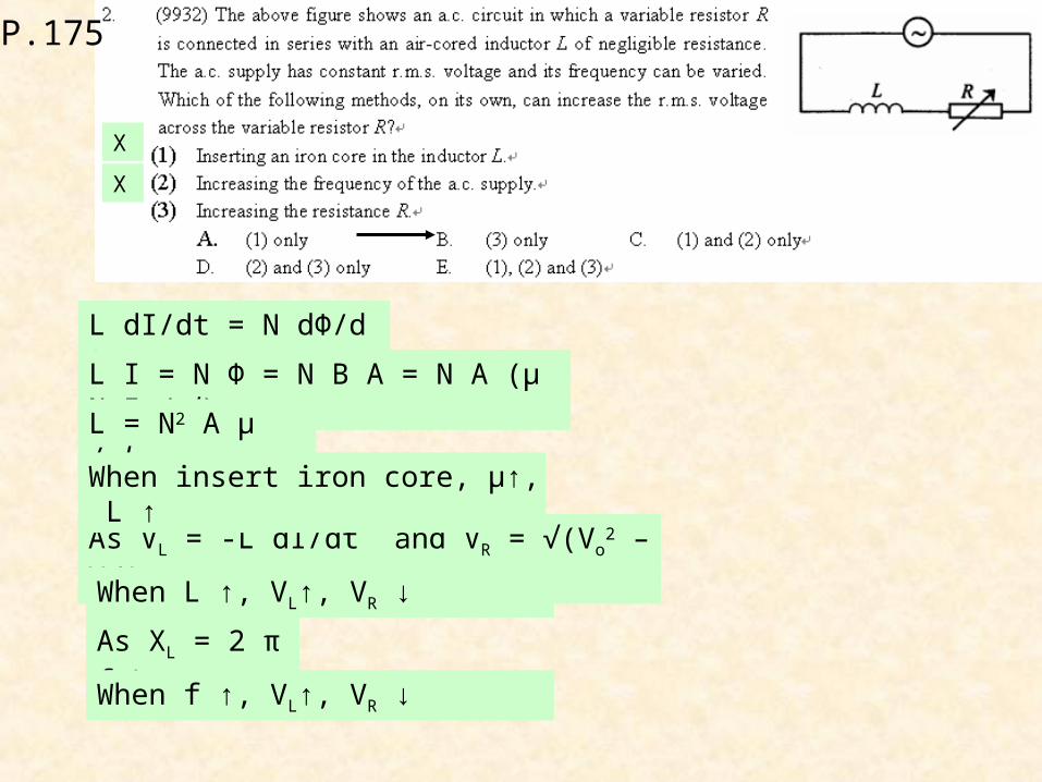
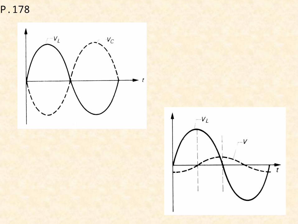
L dI/dt = N dΦ/dt
As VL = -L dI/dt and VR = √(Vo2 – VL
2)
X
X
L I = N Φ = N B A = N A (μ N I / l)
L = N2 A μ / l
When insert iron core, μ↑, L ↑
When L ↑, VL↑, VR ↓
As XL = 2 πf L
When f ↑, VL↑, VR ↓
P.175
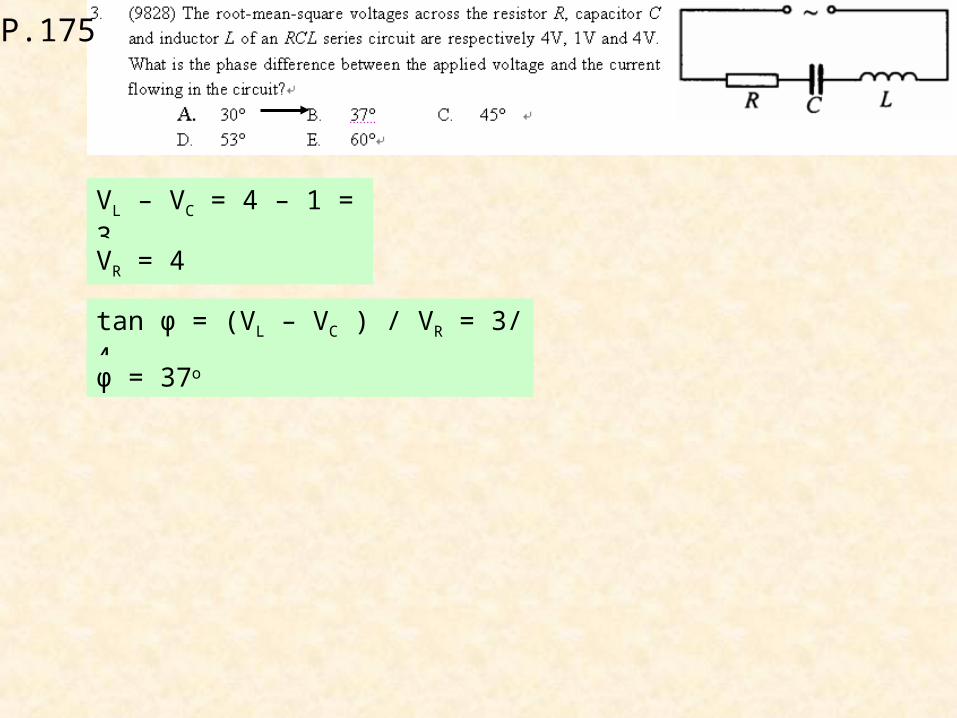
VL – VC = 4 – 1 = 3
tan φ = (VL – VC ) / VR = 3/4
VR = 4
φ = 37o
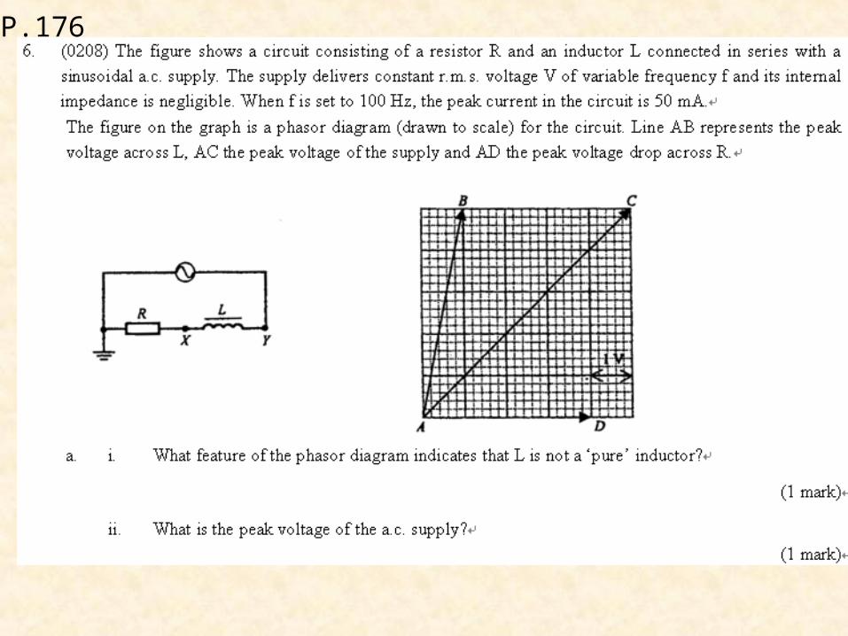
P.176
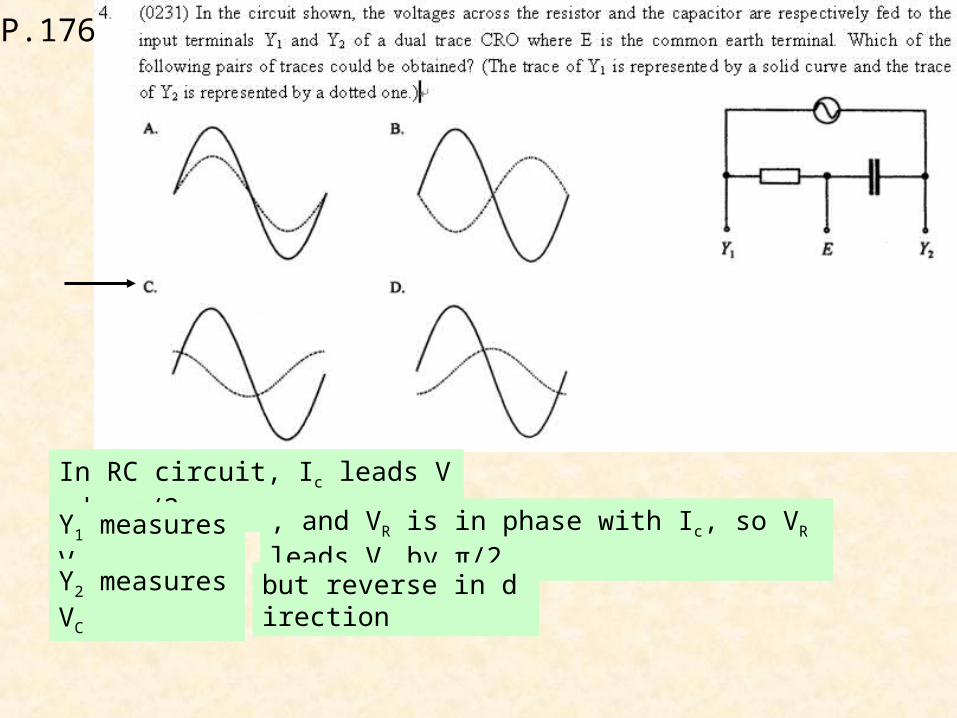
In RC circuit, Ic leads Vc by π/2
Y1 measures VR , and VR is in phase with Ic, so VR leads Vc by π/2
Y2 measures VC but reverse in direction
P.176
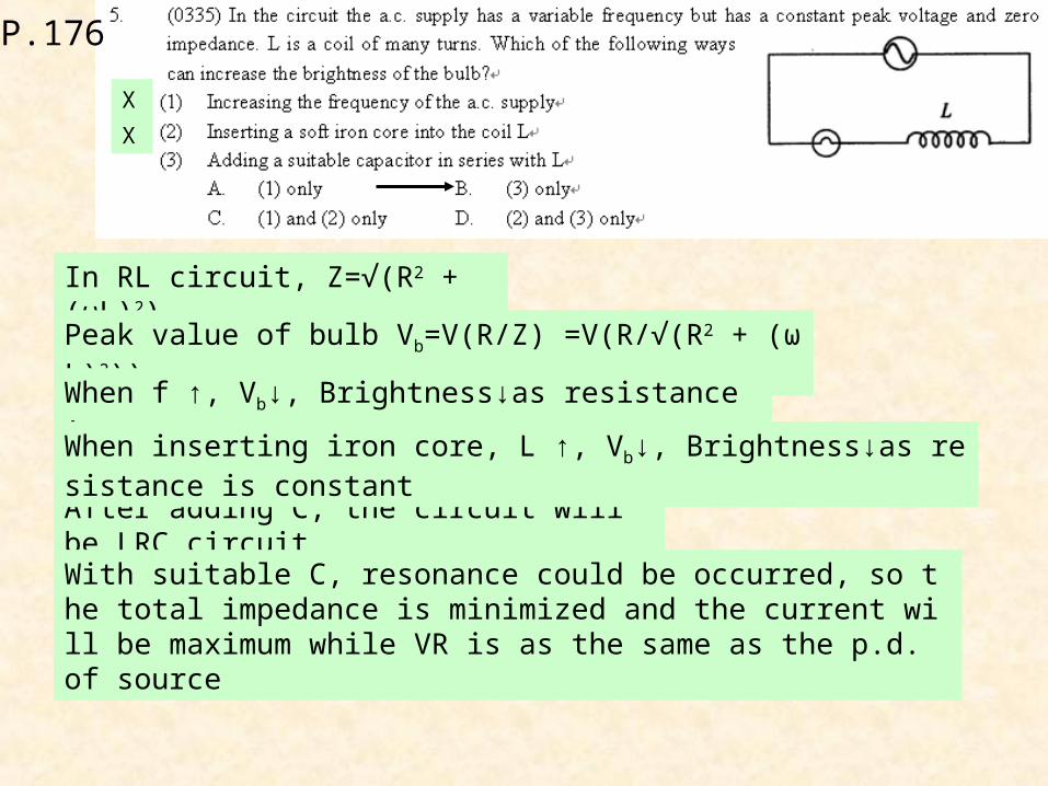
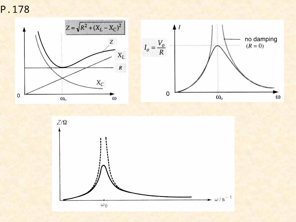
In RL circuit, Z=√(R2 + (ωL)2)
After adding C, the circuit will be LRC circuit
Peak value of bulb Vb=V(R/Z) =V(R/√(R2 + (ωL)2))
When f ↑, Vb↓, Brightness↓as resistance is constant
X
When inserting iron core, L ↑, Vb↓, Brightness↓as resistance is constant
X
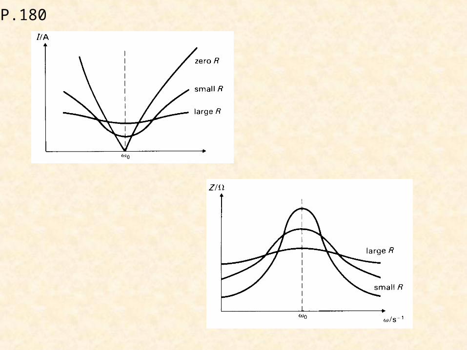
With suitable C, resonance could be occurred, so the total impedance is minimized and the current will be maximum while VR is as the same as the p.d. of source
P.176
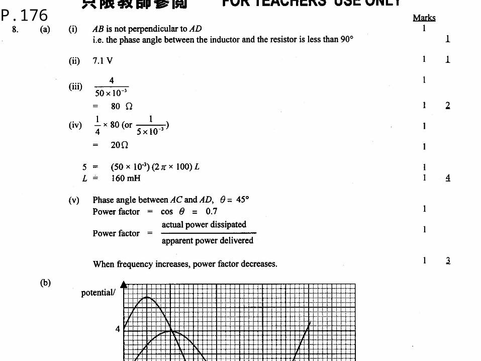
P.176
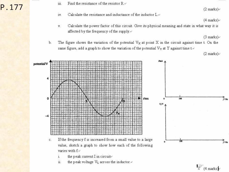
P.177

P.176
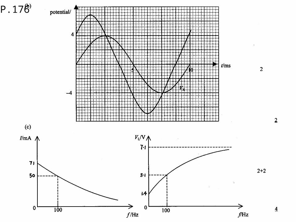
P.176
P.178
P.178
P.179
P.180
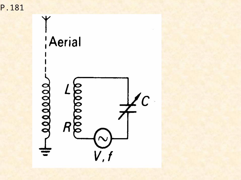
P.181
P.181
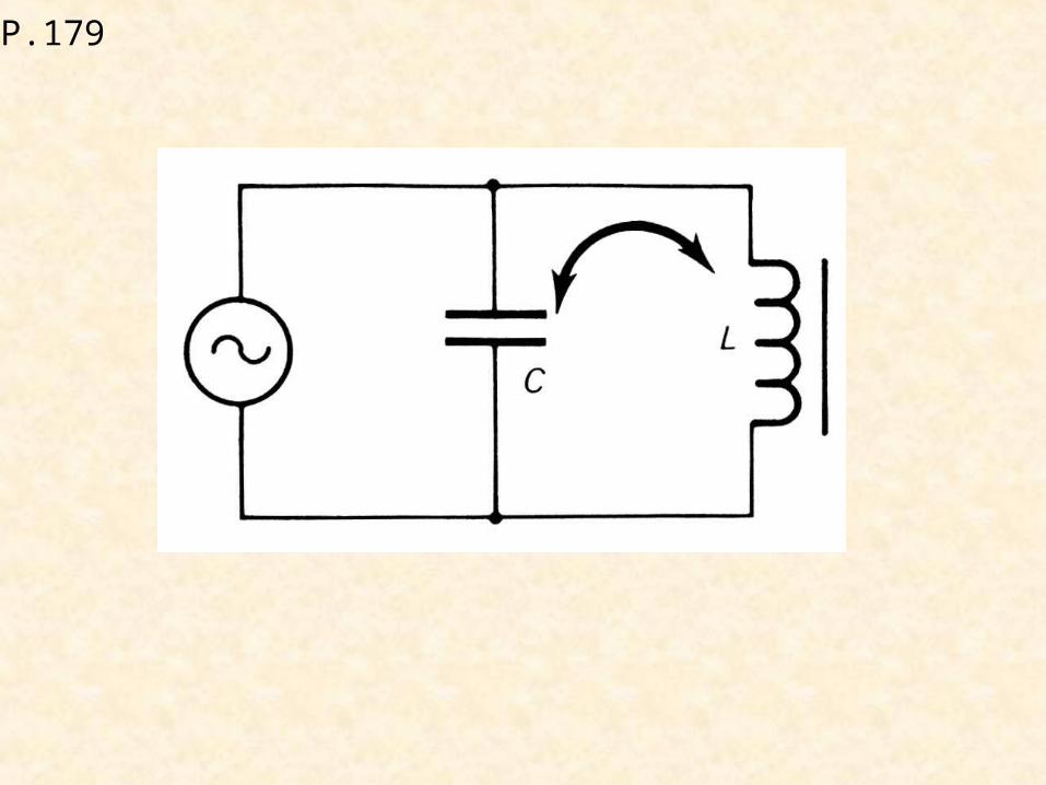
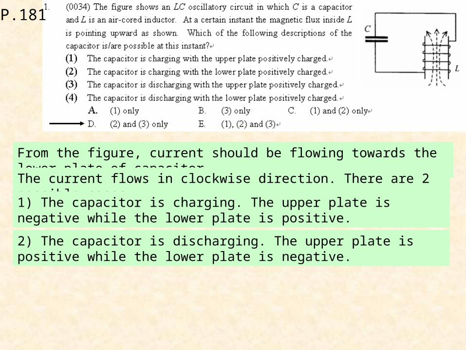
From the figure, current should be flowing towards the lower plate of capacitor
The current flows in clockwise direction. There are 2 possible cases.
1) The capacitor is charging. The upper plate is negative while the lower plate is positive.
2) The capacitor is discharging. The upper plate is positive while the lower plate is negative.

P.181
Electric field CANNOT form closed loops.
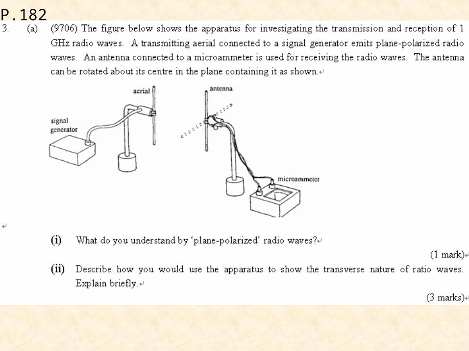
P.182
P.182
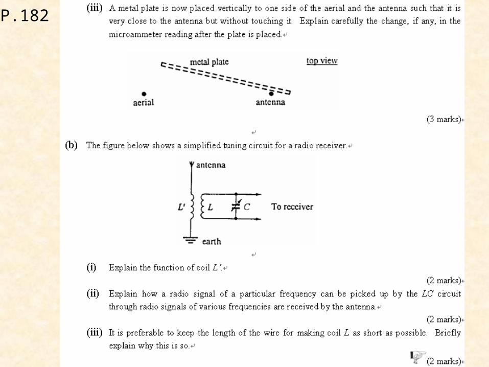
P.182

P.182
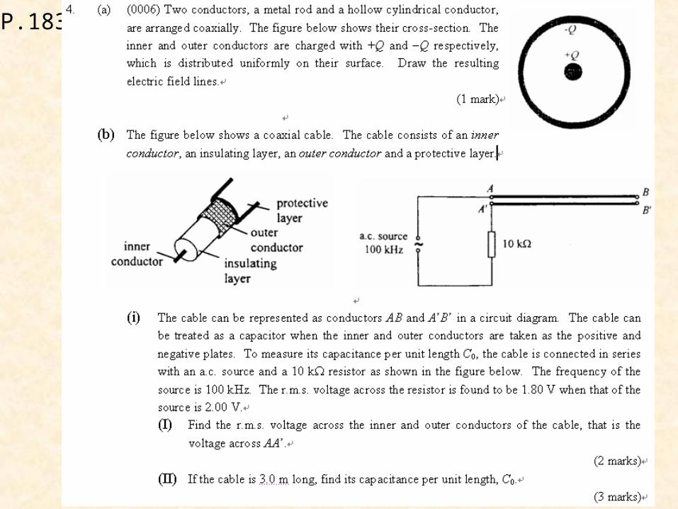
P.183
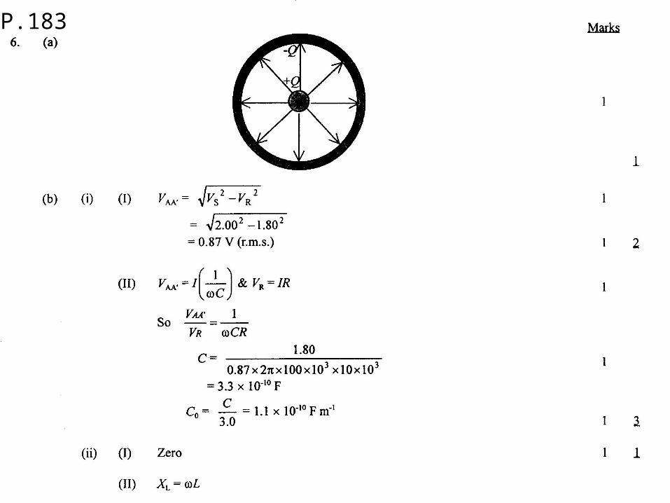
P.183
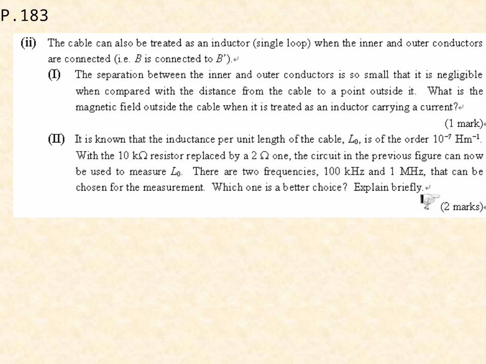
P.183
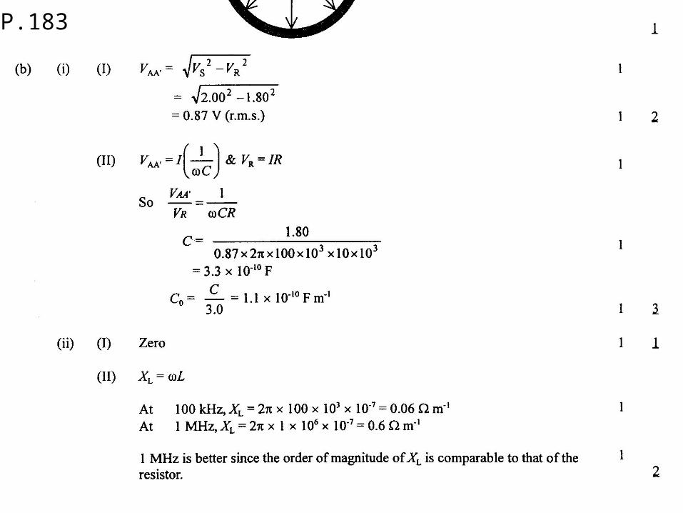
P.183
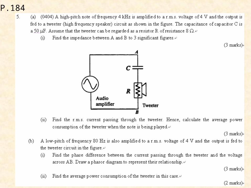
P.184
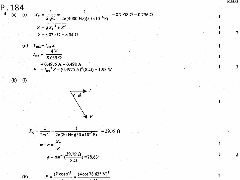
P.184
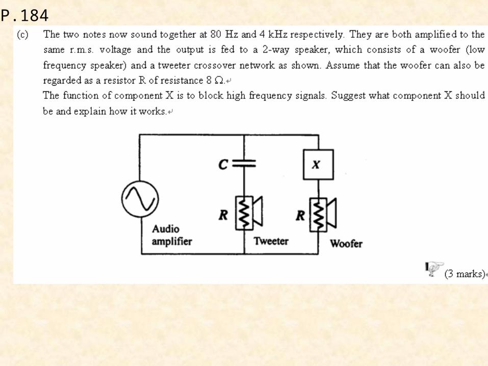
P.184
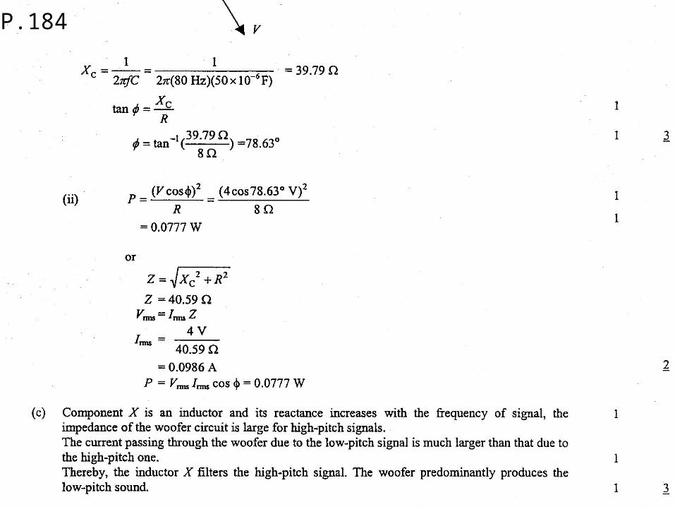
P.184
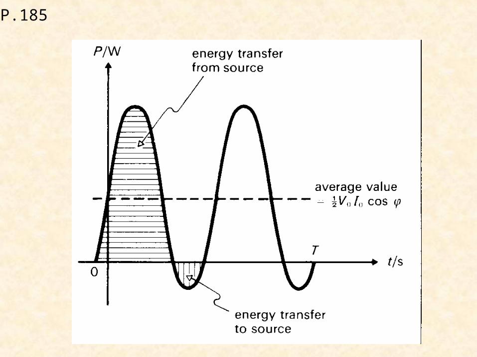
P.185
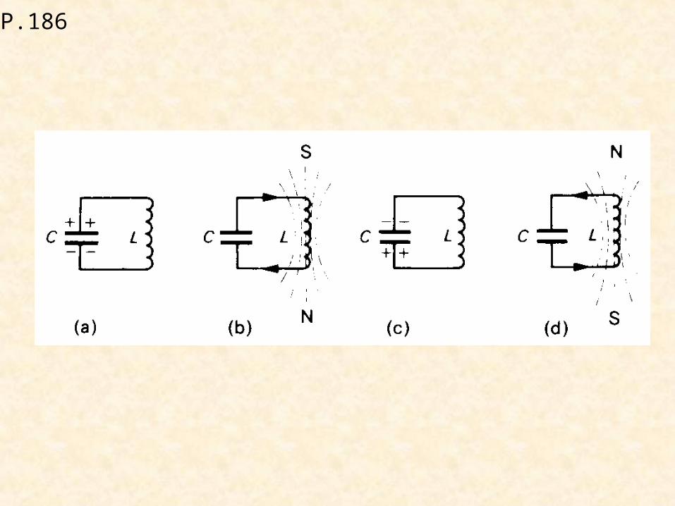
P.186
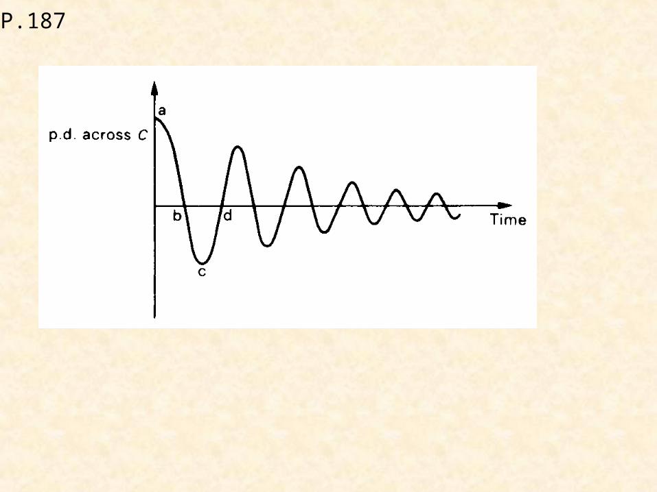
P.187

P.189
+
-
a.c.input R
+
-
d.c.output
+
-a.c.input R
+
-
Nooutput

P.189
+
-a.c. input
R +
-
d.c. output
+
-
+
-a.c. input
R +-
d.c. output+
-
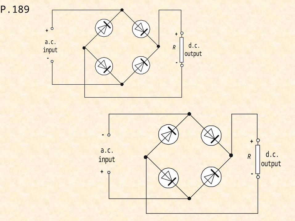
P.189
a.c.input
+
--
R
+
d.c.output
a.c.input
+
-
-
R
+
d.c.output
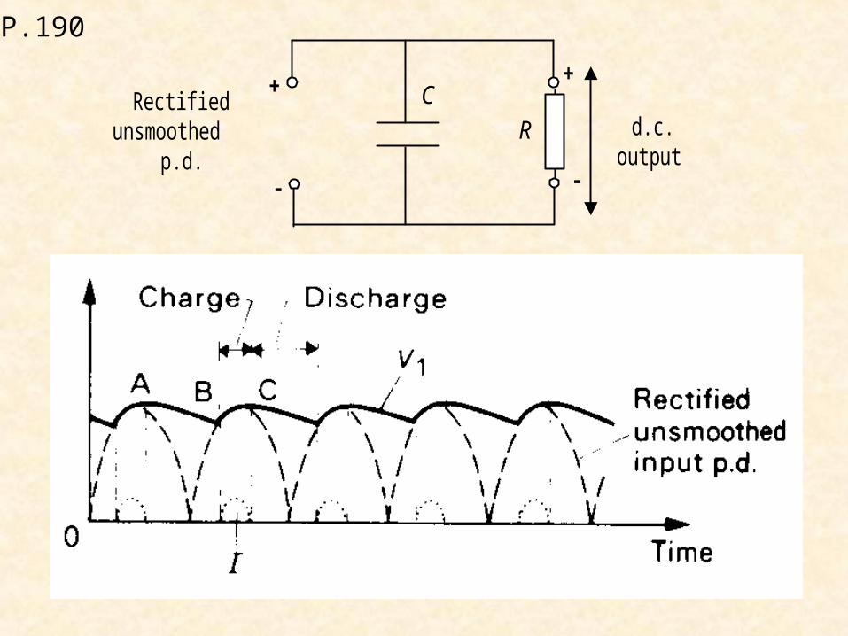
P.190
+
-
Rectifiedunsmoothed
p.d.R
+
-
d.c.output
C
P.190
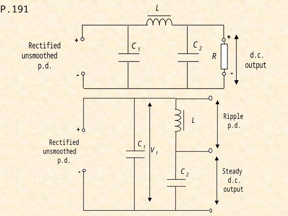
P.191
+
-
Rectifiedunsmoothed
p.d.R
+
-
d.c.output
C 2C 1
L
+
-
Rectifiedunsmoothed
p.d.
Steadyd.c.
output
C 2
C 1
L
V 1
Ripplep.d.
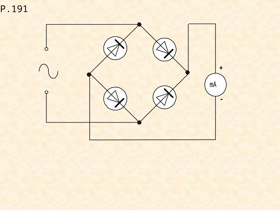
P.191
-
+
mA
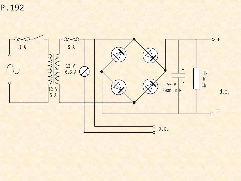
P.192
-
+
d.c.
+
-
1kW
1W50 V2000 m F
a.c.
1 A
12 V5 A
5 A
12 V0.3 A
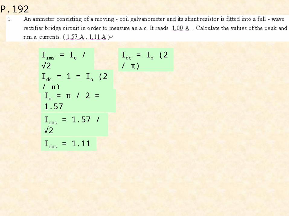
P.192
Irms = Io / √2 Idc = Io (2 / π)
Idc = 1 = Io (2 / π)
Io = π / 2 = 1.57
Irms = 1.57 / √2
Irms = 1.11
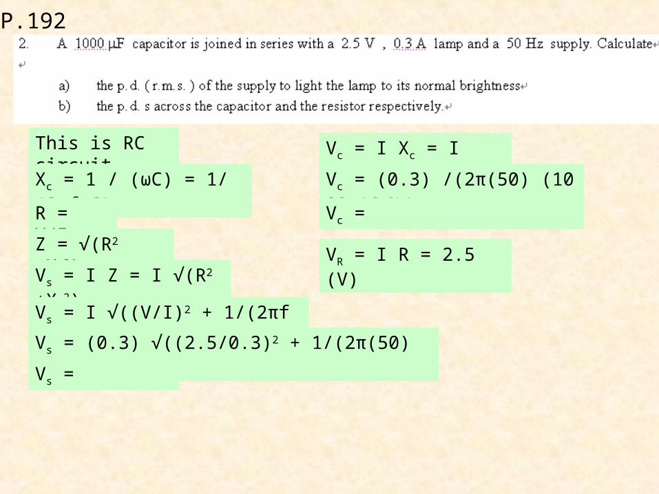
P.192
This is RC circuit.
Xc = 1 / (ωC) = 1/(2πf C)
R = V/I
Z = √(R2 +Xc2)
Vs = I Z = I √(R2 +Xc2)
Vs = I √((V/I)2 + 1/(2πf C)2)
Vs = (0.3) √((2.5/0.3)2 + 1/(2π(50) (1000x10-6))2)
Vs =
Vc = I Xc = I /(2πf C)
Vc = (0.3) /(2π(50) (1000x10-6))
Vc =
VR = I R = 2.5 (V)
P.192
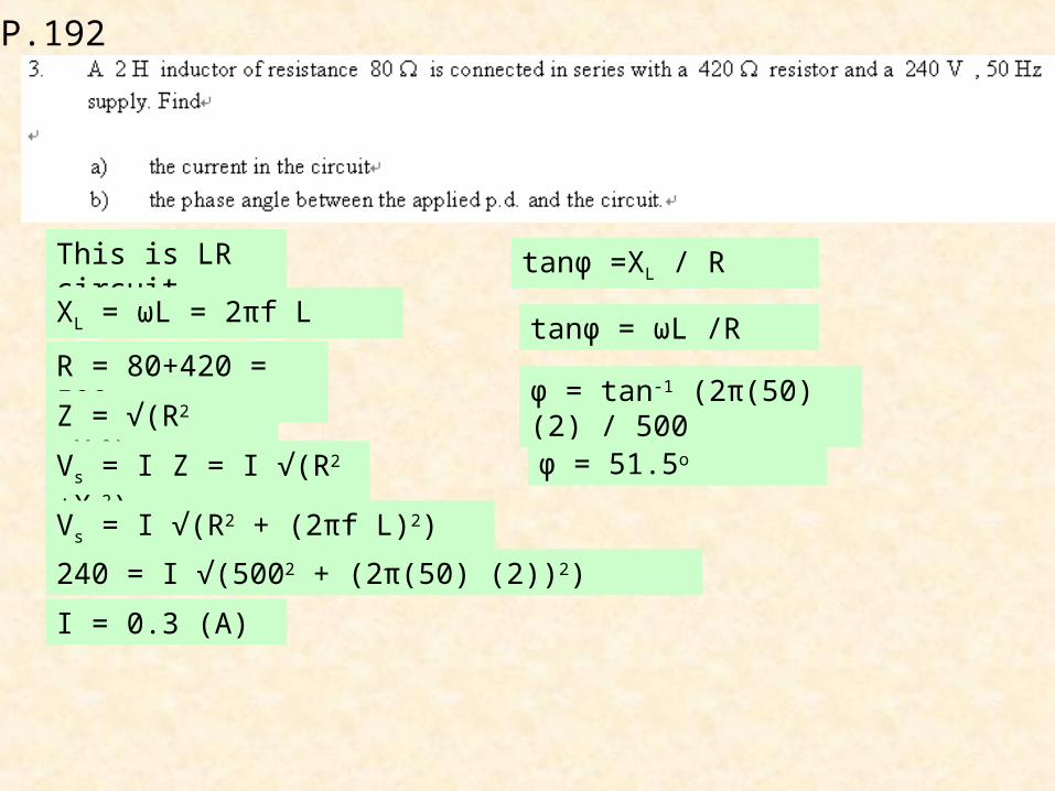
This is LR circuit.
XL = ωL = 2πf L
R = 80+420 = 500
Z = √(R2 +XL2)
Vs = I Z = I √(R2 +XL2)
Vs = I √(R2 + (2πf L)2)
240 = I √(5002 + (2π(50) (2))2)
I = 0.3 (A)
tanφ =XL / R
tanφ = ωL /R
φ = tan-1 (2π(50) (2) / 500
φ = 51.5o
P.193
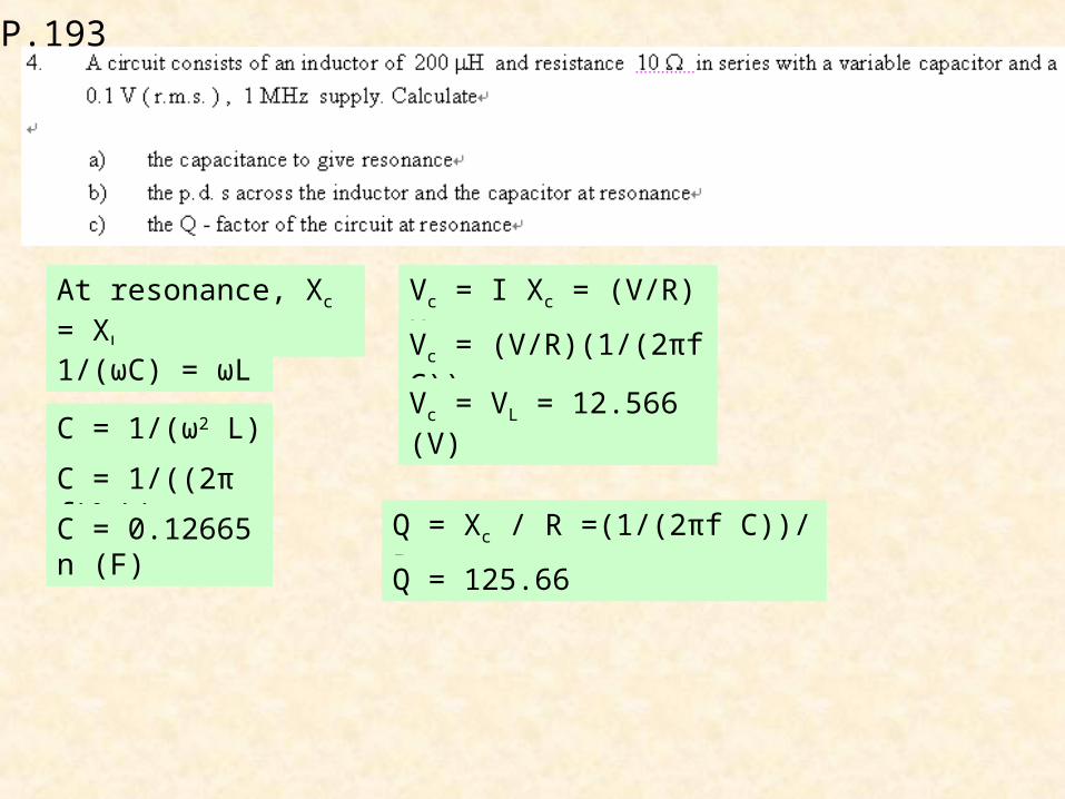
At resonance, Xc = XL
1/(ωC) = ωL
C = 1/(ω2 L)
C = 1/((2πf)2 L)
C = 0.12665n (F)
Vc = I Xc = (V/R) Xc
Vc = (V/R)(1/(2πf C))
Vc = VL = 12.566 (V)
Q = Xc / R =(1/(2πf C))/R
Q = 125.66
P.193
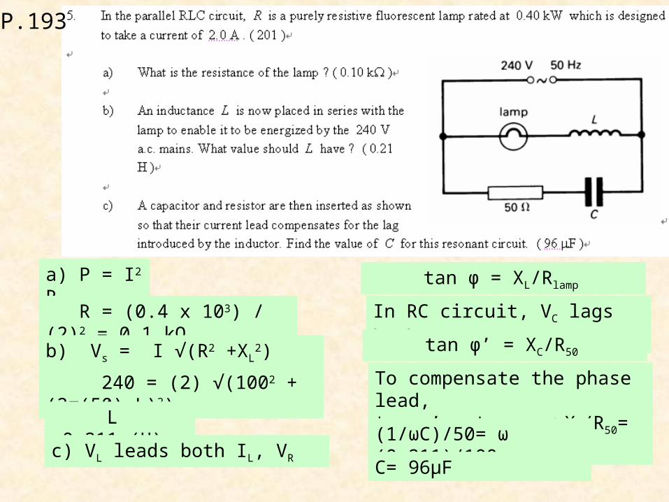
a) P = I2 R
R = (0.4 x 10³) / (2)2 = 0.1 kΩ
b) Vs = I √(R2 +XL2)
240 = (2) √(1002 +(2π(50) L)2)
L =0.211 (H)
c) VL leads both IL, VR
tan φ = XL/Rlamp
In RC circuit, VC lags both IC, VR
tan φ’ = XC/R50
To compensate the phase lead,tan φ’ = tan φ =>XC/R50= XL/Rlamp
(1/ωC)/50= ω (0.211)/100
C= 96μF
P.193
P.193
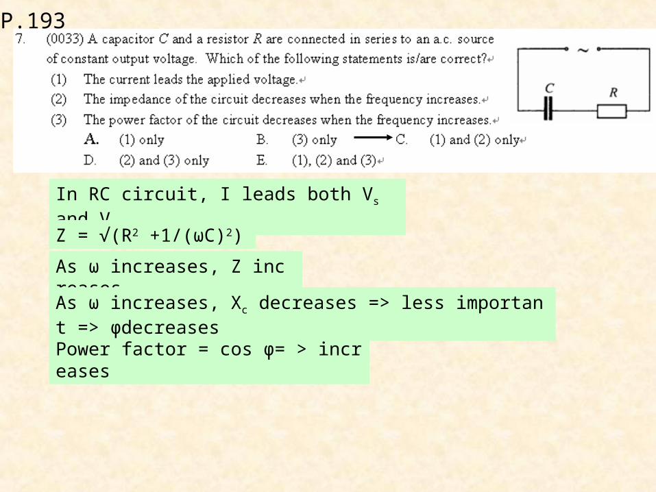
In RC circuit, I leads both Vs and Vc.
Z = √(R2 +1/(ωC)2)
As ω increases, Z increases
Power factor = cos φ= > increases
As ω increases, Xc decreases => less important => φdecreases
P.193
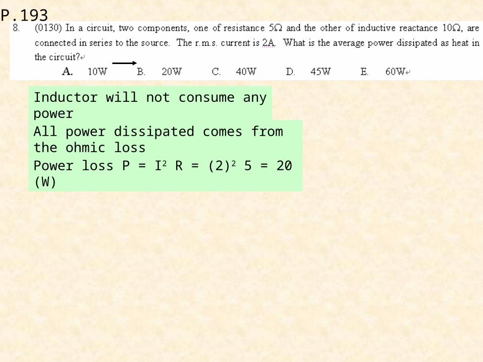
Inductor will not consume any power
All power dissipated comes from the ohmic loss
Power loss P = I2 R = (2)2 5 = 20 (W)

P.193
Z2 = R2 + X2
All power dissipated comes from the ohmic loss
Power loss P = I2 R = (2)2 5 = 20 (W)
132 = R2 + 122
R = 5
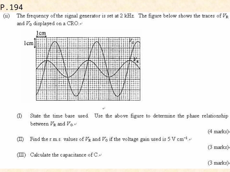
P.194
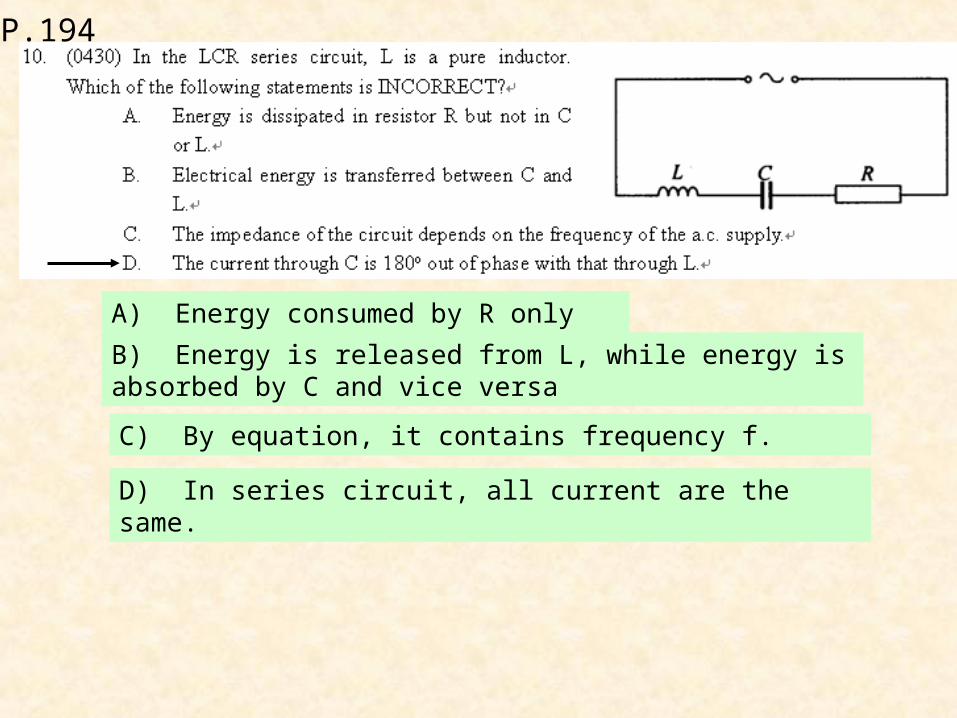
A) Energy consumed by R only or stray C
B) Energy is released from L, while energy is absorbed by C and vice versa
C) By equation, it contains frequency f.
D) In series circuit, all current are the same.

P.194
P.194
P.194

P.194
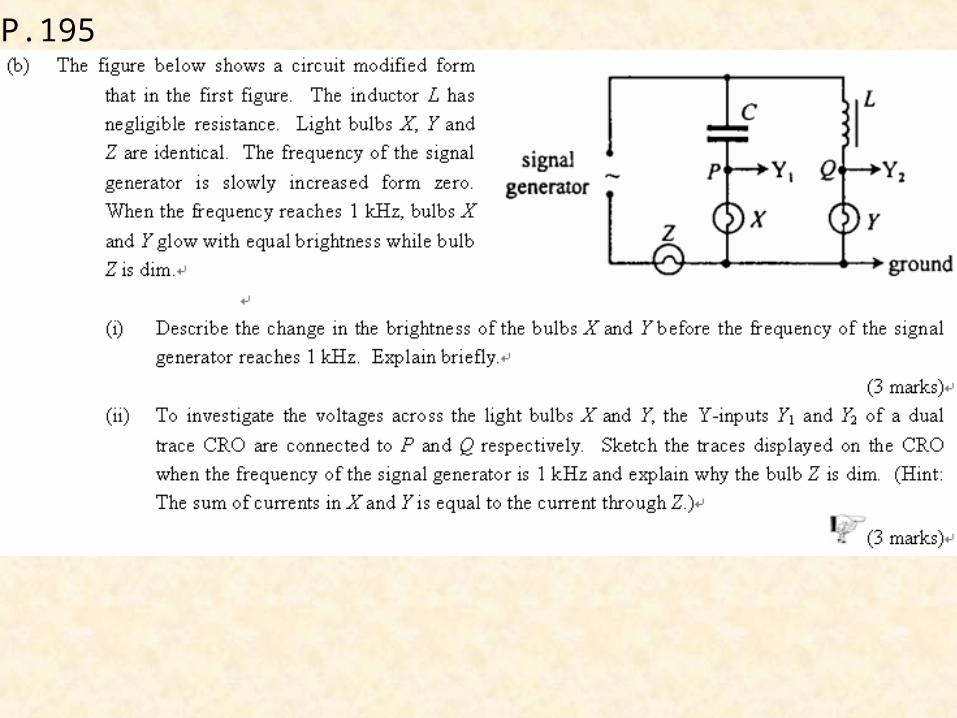
P.195
P.194
P.195
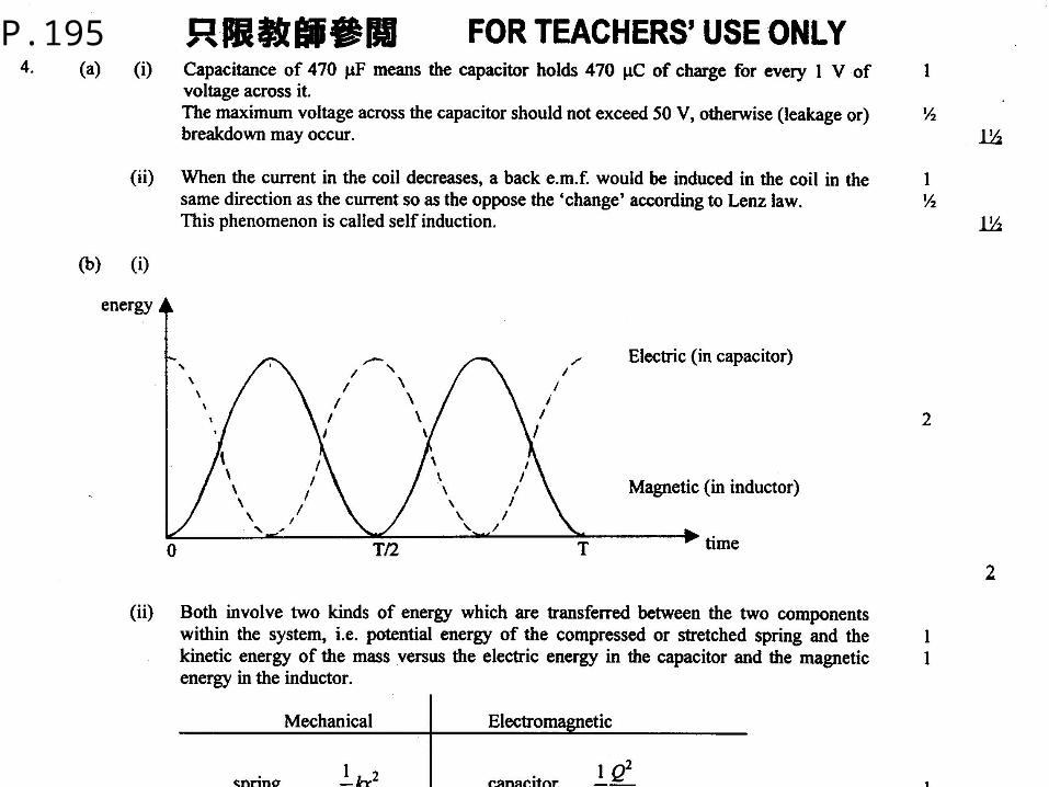
P.195
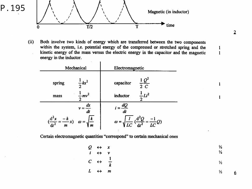
P.195
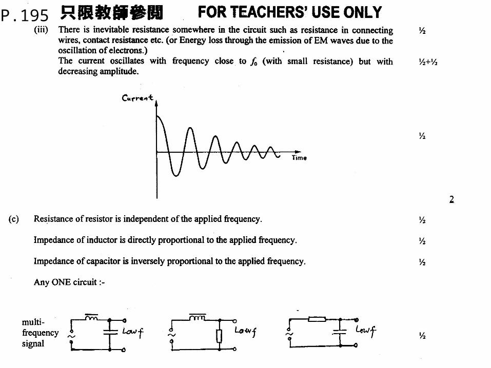
P.195
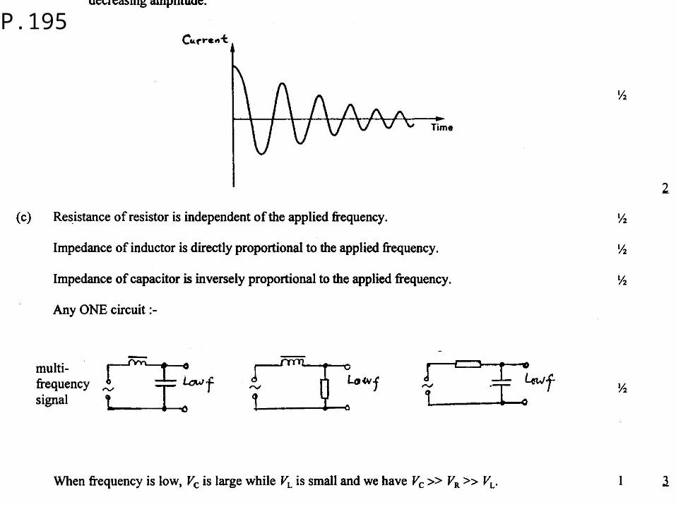
P.195