Aerospace — High-Temperature Machining Guide · PDF filewrought alloys and for cast...
16
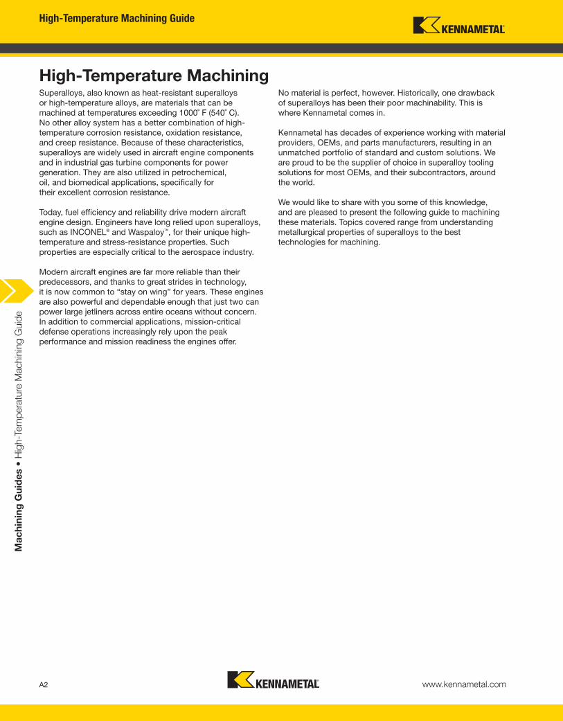
High-Temperature Machining Guide A2 www.kennametal.com Machining Guides • High-Temperature Machining Guide High-Temperature Machining Superalloys, also known as heat-resistant superalloys or high-temperature alloys, are materials that can be machined at temperatures exceeding 1000˚ F (540˚ C). No other alloy system has a better combination of high- temperature corrosion resistance, oxidation resistance, and creep resistance. Because of these characteristics, superalloys are widely used in aircraft engine components and in industrial gas turbine components for power generation. They are also utilized in petrochemical, oil, and biomedical applications, specifically for their excellent corrosion resistance. Today, fuel efficiency and reliability drive modern aircraft engine design. Engineers have long relied upon superalloys, such as INCONEL ® and Waspaloy ™ , for their unique high- temperature and stress-resistance properties. Such properties are especially critical to the aerospace industry. Modern aircraft engines are far more reliable than their predecessors, and thanks to great strides in technology, it is now common to “stay on wing” for years. These engines are also powerful and dependable enough that just two can power large jetliners across entire oceans without concern. In addition to commercial applications, mission-critical defense operations increasingly rely upon the peak performance and mission readiness the engines offer. No material is perfect, however. Historically, one drawback of superalloys has been their poor machinability. This is where Kennametal comes in. Kennametal has decades of experience working with material providers, OEMs, and parts manufacturers, resulting in an unmatched portfolio of standard and custom solutions. We are proud to be the supplier of choice in superalloy tooling solutions for most OEMs, and their subcontractors, around the world. We would like to share with you some of this knowledge, and are pleased to present the following guide to machining these materials. Topics covered range from understanding metallurgical properties of superalloys to the best technologies for machining.
Transcript of Aerospace — High-Temperature Machining Guide · PDF filewrought alloys and for cast...
High-Temperature Machining Guide
A2 www.kennametal.com
Ma
ch
inin
g G
uid
es •
Hig
h-T
em
pera
ture
Machin
ing G
uid
e
High-Temperature MachiningSuperalloys, also known as heat-resistant superalloys
or high-temperature alloys, are materials that can be
machined at temperatures exceeding 1000˚ F (540˚ C).
No other alloy system has a better combination of high-
temperature corrosion resistance, oxidation resistance,
and creep resistance. Because of these characteristics,
superalloys are widely used in aircraft engine components
and in industrial gas turbine components for power
generation. They are also utilized in petrochemical,
oil, and biomedical applications, specifically for
their excellent corrosion resistance.
Today, fuel efficiency and reliability drive modern aircraft
engine design. Engineers have long relied upon superalloys,
such as INCONEL® and Waspaloy™, for their unique high-
temperature and stress-resistance properties. Such
properties are especially critical to the aerospace industry.
Modern aircraft engines are far more reliable than their
predecessors, and thanks to great strides in technology,
it is now common to “stay on wing” for years. These engines
are also powerful and dependable enough that just two can
power large jetliners across entire oceans without concern.
In addition to commercial applications, mission-critical
defense operations increasingly rely upon the peak
performance and mission readiness the engines offer.
No material is perfect, however. Historically, one drawback
of superalloys has been their poor machinability. This is
where Kennametal comes in.
Kennametal has decades of experience working with material
providers, OEMs, and parts manufacturers, resulting in an
unmatched portfolio of standard and custom solutions. We
are proud to be the supplier of choice in superalloy tooling
solutions for most OEMs, and their subcontractors, around
the world.
We would like to share with you some of this knowledge,
and are pleased to present the following guide to machining
these materials. Topics covered range from understanding
metallurgical properties of superalloys to the best
technologies for machining.

High-Temperature Machining Guide
www.kennametal.com
Ma
ch
inin
g G
uid
es •
Hig
h-T
em
pera
ture
Machin
ing G
uid
e
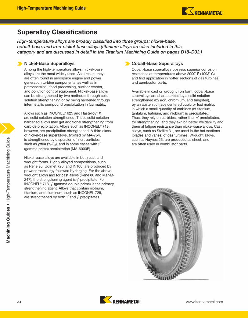
Nickel-Base Superalloys
Among the high-temperature alloys, nickel-base
alloys are the most widely used. As a result, they
are often found in aerospace engine and power
generation turbine components, as well as in
petrochemical, food processing, nuclear reactor,
and pollution control equipment. Nickel-base alloys
can be strengthened by two methods: through solid
solution strengthening or by being hardened through
intermetallic compound precipitation in fcc matrix.
Alloys such as INCONEL® 625 and Hastelloy® X
are solid solution strengthened. These solid solution
hardened alloys may get additional strengthening from
carbide precipitation. Alloys such as INCONEL® 718,
however, are precipitation strengthened. A third class
of nickel-base superalloys, typified by MA-754,
is strengthened by dispersion of inert particles
such as yttria (Y2O3), and in some cases with γ´ (gamma prime) precipitation (MA-6000E).
Nickel-base alloys are available in both cast and
wrought forms. Highly alloyed compositions, such
as Rene 95, Udimet 720, and IN100, are produced by
powder metallurgy followed by forging. For the above
wrought alloys and for cast alloys (Rene 80 and Mar-M-
247), the strengthening agent is γ’ precipitate. For
INCONEL® 718, γ˝ (gamma double prime) is the primary
strengthening agent. Alloys that contain niobium,
titanium, and aluminum, such as INCONEL 725,
are strengthened by both γ´ and γ˝ precipitates.
Cobalt-Base Superalloys
Cobalt-base superalloys possess superior corrosion
resistance at temperatures above 2000˚ F (1093˚ C)
and find application in hotter sections of gas turbines
and combustor parts.
Available in cast or wrought iron form, cobalt-base
superalloys are characterized by a solid solution
strengthened (by iron, chromium, and tungsten),
by an austenitic (face centered cubic or fcc) matrix,
in which a small quantity of carbides (of titanium,
tantalum, hafnium, and niobium) is precipitated.
Thus, they rely on carbides, rather than γ´ precipitates,
for strengthening, and they exhibit better weldability and
thermal fatigue resistance than nickel-base alloys. Cast
alloys, such as Stellite 31, are used in the hot sections
(blades and vanes) of gas turbines. Wrought alloys,
such as Haynes 25, are produced as sheet, and
are often used in combustor parts.
A4
Superalloy Classifications
High-temperature alloys are broadly classified into three groups: nickel-base,
cobalt-base, and iron-nickel-base alloys (titanium alloys are also included in this
category and are discussed in detail in the Titanium Machining Guide on pages D18–D33.)
High-Temperature Machining Guide
www.kennametal.com
Ma
ch
inin
g G
uid
es •
Hig
h-T
em
pera
ture
Machin
ing G
uid
e
Iron-Nickel-Base Superalloys
Iron-nickel-base superalloys are similar to wrought
austenitic stainless steels, except for the addition of
γ´ strengthening agent. They have the lowest elevated
temperature strength among the three groups of
superalloys, and are generally used in the wrought
condition in gas turbine disks and blades.
Most wrought alloys contain high levels of chromium,
which provide corrosion resistance. They owe their
high-temperature strength to solid solution hardening
(hardening produced by solute atoms dissolved in
the alloy matrix) or precipitation hardening (hardening
produced by precipitate particles).
Alloys such as Haynes 556 and 19-9 DL are solid
solution strengthened with molybdenum, tungsten,
titanium, and niobium. Alloys such as A286 and Incoloy
909 are precipitation hardened. The most common
precipitates are γ´, (Ni3 [Al, Ti]) (e.g., A286), and γ˝, (Ni3Nb) (e.g., Incoloy 909).
Another group of iron-nickel-base alloys contains
high carbon content and is strengthened by carbides,
nitrides, and solid solution strengthening. A group of
alloys, based on Fe-Ni-Co and strengthened by γ’,combines high strength with a low thermal expansion
coefficient (e.g., Incoloy 903, 907, and 909) and finds
application in shafts, rings, and casings for gas turbines.
Metallurgy of Superalloys
High-temperature alloys derive their strength from
solid solution hardening, gamma prime precipitation
hardening, or oxide dispersion strengthening.
Metallurgy is controlled by adjustments in composition
as well as through processing, including the aging
treatment where the solution-annealed alloy is heated
until one or more phases occur. The resulting austenitic
matrix — combined with a wide variety of secondary
phases such as metal carbides (MC, M23C6, M7C3),
γ´, the ordered fcc strengthening phase (Ni3 [Al, Ti]),
or the γ˝ (Ni3Nb) — impart to the alloys their excellent
high-temperature strength.
Superalloy components are typically available in cast,
wrought (forged), and sintered (powder metallurgy) forms.
Some important characteristics to consider about each
form:
• Cast alloys have coarser grain sizes and exceptional
creep strength.
• Wrought alloys have more uniform and finer grain
sizes and possess higher tensile and fatigue strength.
• Powder metallurgical processing enables production
of more complicated and near-net shapes.
A5
High-Temperature Machining Guide
www.kennametal.com
Ma
ch
inin
g G
uid
es •
Hig
h-T
em
pera
ture
Machin
ing G
uid
e
Nickel-Base Superalloys
• Properties: High-temperature creep resistance, corrosion resistance, and thermal shock resistance.
• Potential Source(s) of Strengthening:
— Solid solution strengthening with Co, Cr, Fe, Mo, W, Ta, and Re (e.g., INCONEL® 600 or INCONEL 625)
— γ´ (Ni3 [Al, Ti]) precipitation hardening (e.g., INCONEL 718)
— Oxide-dispersion strengthening (e.g., IN-100 or Waspaloy®)
• Applications: Aerospace engine components.
Cobalt-Base Superalloys
• Properties: High-temperature creep resistance and superior corrosion resistance.
• Potential Source(s) of Strengthening: Primarily solid solution strengthening (Cr, Fe, and W),
but can have additional strengthening by carbides (Ti, Ta, Hf, and Nb).
• Applications: Hot sections (blades and vanes) of gas turbines and combustor parts.
Iron-Nickel-Base Superalloys
• Properties: Lowest elevated temperature strength among the superalloys, high corrosion resistance.
• Potential Source(s) of Strengthening:
— Solid solution strengthening with Cr, Mo, and W (e.g., Discaloy)
— γ´ (Ni3 [Al, Ti]) precipitation hardening (e.g., A286)
• Applications: Gas turbine disks and blades.
A6
Superalloy Classifications (continued)
High-Temperature Machining Guide
www.kennametal.com
Ma
ch
inin
g G
uid
es •
Hig
h-T
em
pera
ture
Machin
ing G
uid
e
Machinability of Superalloys
As previously mentioned, superalloys generally
have poor machinability. The very characteristics
that provide superior high-temperature strength
also make them difficult to machine. Additionally,
decreased cutting tool speeds can limit productivity.
The main challenges to machining superalloys include:
• The high strength of nickel-base superalloys at cutting
temperatures causes high cutting forces, generates
more heat at the tool tip (compared to alloy steel
machining), and limits their speed capability.
• The low thermal conductivity of these alloys transfers
heat produced during machining to the tool,
subsequently increasing tool tip temperatures
and causing excessive tool wear, which can
limit cutting speeds and reduce useful tool life.
• The presence of hard, abrasive intermetallic
compounds and carbides in these alloys
causes severe abrasive wear on the tool tip.
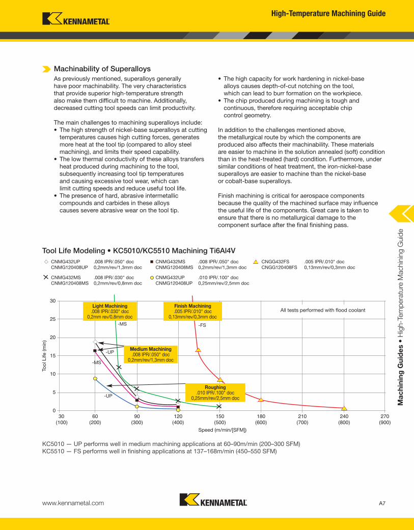
Tool Life Modeling • KC5010/KC5510 Machining Ti6Al4V
30
25
20
15
10
5
030 60 90 120 150 180 210 240 270
(100) (200) (300) (400) (500) (600) (700) (800) (900)Speed (m/min/[SFM])
Too
l Life (m
in)
CNMG432UP .008 IPR/.050" doc
CNMG120408UP 0,2mm/rev/1,3mm doc
CNMG432MS .008 IPR/.030" doc
CNMG120408MS 0,2mm/rev/0,8mm doc
CNMG432MS .008 IPR/.050" doc
CNMG120408MS 0,2mm/rev/1,3mm doc
CNMG432UP .010 IPR/.100" doc
CNMG120408UP 0,25mm/rev/2,5mm doc
CNGG432FS .005 IPR/.010" doc
CNGG120408FS 0,13mm/rev/0,3mm doc
Finish Machining.005 IPR/.010" doc
0,13mm/rev/0,3mm doc
Light Machining.008 IPR/.030" doc
0,2mm rev/0,8mm doc
-FS-MS
-UP
-MS
-UP
All tests performed with flood coolant
KC5010 — UP performs well in medium machining applications at 60–90m/min (200–300 SFM)
KC5510 — FS performs well in finishing applications at 137–168m/min (450–550 SFM)
• The high capacity for work hardening in nickel-base
alloys causes depth-of-cut notching on the tool,
which can lead to burr formation on the workpiece.
• The chip produced during machining is tough and
continuous, therefore requiring acceptable chip
control geometry.
In addition to the challenges mentioned above,
the metallurgical route by which the components are
produced also affects their machinability. These materials
are easier to machine in the solution annealed (soft) condition
than in the heat-treated (hard) condition. Furthermore, under
similar conditions of heat treatment, the iron-nickel-base
superalloys are easier to machine than the nickel-base
or cobalt-base superalloys.
Finish machining is critical for aerospace components
because the quality of the machined surface may influence
the useful life of the components. Great care is taken to
ensure that there is no metallurgical damage to the
component surface after the final finishing pass.
Medium Machining.008 IPR/.050" doc
0,2mm/rev/1,3mm doc
Roughing.010 IPR/.100" doc
0,25mm/rev/2,5mm doc
A7
High-Temperature Machining Guide
www.kennametal.com
Ma
ch
inin
g G
uid
es •
Hig
h-T
em
pera
ture
Machin
ing G
uid
e
Machining Guidelines for Superalloys
When machining with CARBIDE tooling:
• PVD coated carbide tools with positive rakes are suitable for finishing and medium machining.
— Reduces cutting forces and temperatures
— Minimizes part deflection
• Always maintain high feed-rate and depth of cut.
— Minimizes hardening
• Use a generous quantity of coolant with carbide tools.
— Reduces temperature build-up and rapid tool wear
• Utilize high-pressure coolant whenever possible.
• For rough cutting, T-landed ceramic inserts are recommended.
• With carbide inserts, use moderate cutting speeds.
— Minimizes tool tip temperatures and encourages longer tool life
• Never allow tool to dwell.
— Minimizes possibility of work hardening and subsequent problems in downstream process
When machining with CERAMIC tooling:
• Higher cutting speeds of 600–4000 SFM are possible with ceramic tools
(SiAlON and SiC whisker-reinforced Al2O3).
• There is no need for coolant.
• Depth-of-cut notching is more pronounced (versus carbides).
• When notching is severe (primarily in roughing cuts on forgings with scale), use higher lead angle.
— Reduces tool pressure and work hardening and improves surface finish
When machining with PCBN tooling:
• Use low-content PCBN grades for finishing and semi-finishing at low depth of cut, but optimize
the cutting conditions for each individual part, and pay close attention to surface condition.
• Use sharp edge uncoated grades for better surface finishes and close tolerance.
• Use coated grades to increase tool life and productivity.
A8
High-Temperature Machining Guide
www.kennametal.com
Ma
ch
inin
g G
uid
es •
Hig
h-T
em
pera
ture
Machin
ing G
uid
e
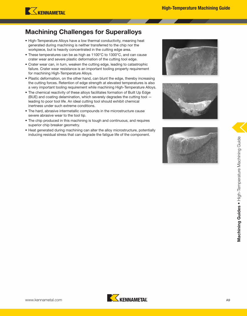
Machining Challenges for Superalloys
• High-Temperature Alloys have a low thermal conductivity, meaning heat
generated during machining is neither transferred to the chip nor the
workpiece, but is heavily concentrated in the cutting edge area.
• These temperatures can be as high as 1100°C to 1300°C, and can cause
crater wear and severe plastic deformation of the cutting tool edge.
• Crater wear can, in turn, weaken the cutting edge, leading to catastrophic
failure. Crater wear resistance is an important tooling property requirement
for machining High-Temperature Alloys.
• Plastic deformation, on the other hand, can blunt the edge, thereby increasing
the cutting forces. Retention of edge strength at elevated temperatures is also
a very important tooling requirement while machining High-Temperature Alloys.
• The chemical reactivity of these alloys facilitates formation of Built Up Edge
(BUE) and coating delamination, which severely degrades the cutting tool —
leading to poor tool life. An ideal cutting tool should exhibit chemical
inertness under such extreme conditions.
• The hard, abrasive intermetallic compounds in the microstructure cause
severe abrasive wear to the tool tip.
• The chip produced in this machining is tough and continuous, and requires
superior chip breaker geometry.
• Heat generated during machining can alter the alloy microstructure, potentially
inducing residual stress that can degrade the fatigue life of the component.
A9
High-Temperature Machining Guide
www.kennametal.com
Ma
ch
inin
g G
uid
es •
Hig
h-T
em
pera
ture
Machin
ing G
uid
e
Troubleshooting
High-Temperature Alloy Characteristics and Troubleshooting
Nickel-Base, Heat-Resistant Alloys (140–475 HB) (≤48 HRC)
Astroloy, Hastelloy®, B/C/C-276/X, INCONEL® 601/617/625/700/706/718, IN100,
Incoloy® 901, MAR-M200, Nimonic®, Rene 41, Udimet®, Waspaloy®, Monel®
Material Characteristics
• High forces at the cutting edge.
• High heat concentration in cutting area.
• High cutting speed may cause insert failure
by plastic deformation.
• Relatively poor tool life.
• Small depths of cut are difficult.
• Rapid workhardening.
• Usually abrasive rather than hard.
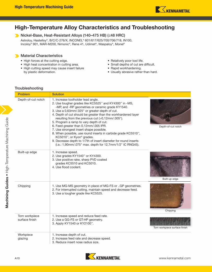
Problem Solution
Depth-of-cut notch 1. Increase toolholder lead angle.
2. Use tougher grades like KC5525™ and KY4300™ in -MS,
-MP, and -RP geometries or ceramic grade KY1540.
3. Use a 0,63mm/.025" or greater depth of cut.
4. Depth of cut should be greater than the workhardened layer
resulting from the previous cut (>0,12mm/.005").
5. Program a ramp to vary depth of cut.
6. Feed greater than 0,12mm/.005 IPR.
7. Use strongest insert shape possible.
8. When possible, use round inserts in carbide grade KC5510™,
KC5010™, or Kyon® grades.
9. Decrease depth to 1/7th of insert diameter for round inserts
(i.e.: 1,90mm/.075" max. depth for 12,7mm/1/2" IC RNG45).
Built-up edge 1. Increase speed.
2. Use grades KY1540™ or KY4300.
3. Use positive rake, sharp PVD coated
grades KC5510 and KC5010.
4. Use flood coolant.
Chipping 1. Use MG-MS geometry in place of MG-FS or ..GP geometries.
2. For interrupted cutting, maintain speed and decrease feed.
3. Use a tougher grade like KC5525.
Torn workpiece 1. Increase speed and reduce feed rate.
surface finish 2. Use a GG-FS or GT-HP geometry.
3. Apply KY1540 or KY2100™.
Workpiece 1. Increase depth of cut.
glazing 2. Increase feed rate and decrease speed.
3. Reduce insert nose radius size.
Depth-of-cut notch
Built-up edge
Chipping
A10
Torn workpiece surface finish
High-Temperature Machining Guide
www.kennametal.com
Ma
ch
inin
g G
uid
es •
Hig
h-T
em
pera
ture
Machin
ing G
uid
e
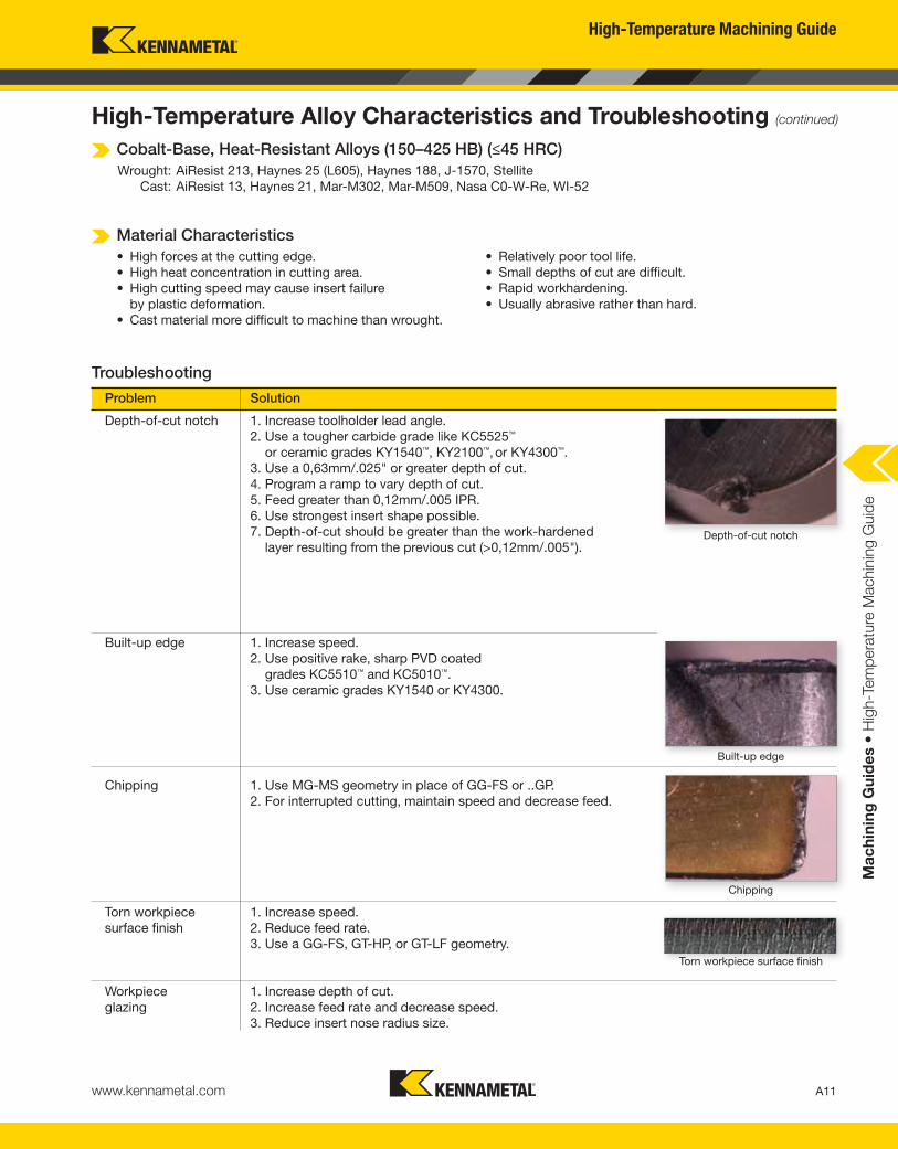
High-Temperature Alloy Characteristics and Troubleshooting (continued)
Cobalt-Base, Heat-Resistant Alloys (150–425 HB) (≤45 HRC)
Wrought: AiResist 213, Haynes 25 (L605), Haynes 188, J-1570, Stellite
Cast: AiResist 13, Haynes 21, Mar-M302, Mar-M509, Nasa C0-W-Re, WI-52
Material Characteristics
• High forces at the cutting edge.
• High heat concentration in cutting area.
• High cutting speed may cause insert failure
by plastic deformation.
• Cast material more difficult to machine than wrought.
• Relatively poor tool life.
• Small depths of cut are difficult.
• Rapid workhardening.
• Usually abrasive rather than hard.
Troubleshooting
Problem Solution
Depth-of-cut notch
Built-up edge
Chipping
A11
Torn workpiece surface finish
Depth-of-cut notch 1. Increase toolholder lead angle.
2. Use a tougher carbide grade like KC5525™
or ceramic grades KY1540™, KY2100™,or KY4300™.
3. Use a 0,63mm/.025" or greater depth of cut.
4. Program a ramp to vary depth of cut.
5. Feed greater than 0,12mm/.005 IPR.
6. Use strongest insert shape possible.
7. Depth-of-cut should be greater than the work-hardened
layer resulting from the previous cut (>0,12mm/.005").
Built-up edge 1. Increase speed.
2. Use positive rake, sharp PVD coated
grades KC5510™ and KC5010™.
3. Use ceramic grades KY1540 or KY4300.
Chipping 1. Use MG-MS geometry in place of GG-FS or ..GP.
2. For interrupted cutting, maintain speed and decrease feed.
Torn workpiece 1. Increase speed.
surface finish 2. Reduce feed rate.
3. Use a GG-FS, GT-HP, or GT-LF geometry.
Workpiece 1. Increase depth of cut.
glazing 2. Increase feed rate and decrease speed.
3. Reduce insert nose radius size.
High-Temperature Machining Guide
www.kennametal.com
Ma
ch
inin
g G
uid
es •
Hig
h-T
em
pera
ture
Machin
ing G
uid
e
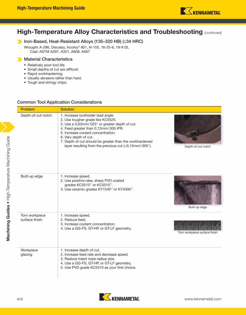
High-Temperature Alloy Characteristics and Troubleshooting (continued)
Iron-Based, Heat-Resistant Alloys (135–320 HB) (≤34 HRC)
Wrought: A-286, Discaloy, Incoloy® 801, N-155, 16-25-6, 19-9 DL
Cast: ASTM A297, A351, A608, A567
Material Characteristics
• Relatively poor tool life.
• Small depths of cut are difficult.
• Rapid workhardening.
• Usually abrasive rather than hard.
• Tough and stringy chips.
Common Tool Application Considerations
Problem Solution
Depth-of-cut notch 1. Increase toolholder lead angle.
2. Use tougher grade like KC5525.
3. Use a 0,63mm/.025" or greater depth of cut.
4. Feed greater than 0,12mm/.005 IPR.
5. Increase coolant concentration.
6. Vary depth of cut.
7. Depth of cut should be greater than the workhardened
layer resulting from the previous cut (>0,12mm/.005").
Built-up edge 1. Increase speed.
2. Use positive rake, sharp PVD coated
grades KC5510™ or KC5010™.
3. Use ceramic grades KY1540™ or KY4300™.
Torn workpiece 1. Increase speed.
surface finish 2. Reduce feed.
3. Increase coolant concentration.
4. Use a GG-FS, GT-HP, or GT-LF geometry.
Workpiece 1. Increase depth of cut.
glazing 2. Increase feed rate and decrease speed.
3. Reduce insert nose radius size.
4. Use a GG-FS, GT-HP, or GT-LF geometry.
5. Use PVD grade KC5510 as your first choice.
Depth-of-cut notch
Built-up edge
A12
Torn workpiece surface finish
High-Temperature Machining Guide
www.kennametal.com
Ma
ch
inin
g G
uid
es •
Hig
h-T
em
pera
ture
Machin
ing G
uid
e
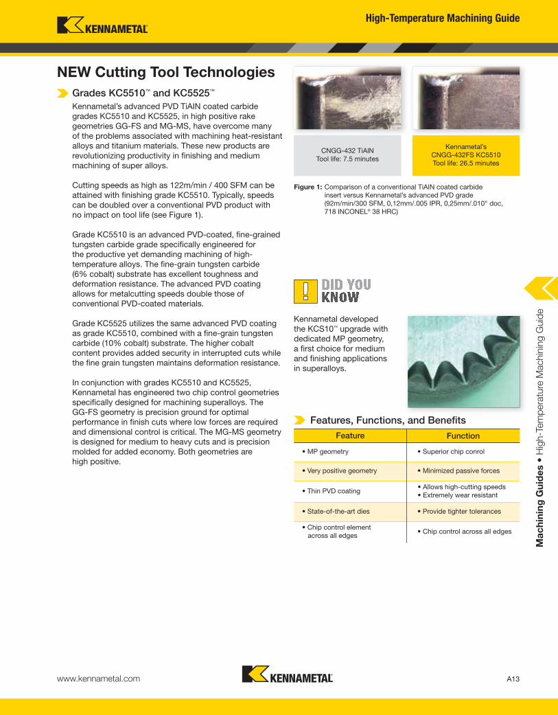
Grades KC5510™ and KC5525™
Kennametal’s advanced PVD TiAIN coated carbide
grades KC5510 and KC5525, in high positive rake
geometries GG-FS and MG-MS, have overcome many
of the problems associated with machining heat-resistant
alloys and titanium materials. These new products are
revolutionizing productivity in finishing and medium
machining of super alloys.
Cutting speeds as high as 122m/min / 400 SFM can be
attained with finishing grade KC5510. Typically, speeds
can be doubled over a conventional PVD product with
no impact on tool life (see Figure 1).
Grade KC5510 is an advanced PVD-coated, fine-grained
tungsten carbide grade specifically engineered for
the productive yet demanding machining of high-
temperature alloys. The fine-grain tungsten carbide
(6% cobalt) substrate has excellent toughness and
deformation resistance. The advanced PVD coating
allows for metalcutting speeds double those of
conventional PVD-coated materials.
Grade KC5525 utilizes the same advanced PVD coating
as grade KC5510, combined with a fine-grain tungsten
carbide (10% cobalt) substrate. The higher cobalt
content provides added security in interrupted cuts while
the fine grain tungsten maintains deformation resistance.
In conjunction with grades KC5510 and KC5525,
Kennametal has engineered two chip control geometries
specifically designed for machining superalloys. The
GG-FS geometry is precision ground for optimal
performance in finish cuts where low forces are required
and dimensional control is critical. The MG-MS geometry
is designed for medium to heavy cuts and is precision
molded for added economy. Both geometries are
high positive.
Kennametal’s
CNGG-432FS KC5510
Tool life: 26.5 minutes
CNGG-432 TiAlN
Tool life: 7.5 minutes
Figure 1: Comparison of a conventional TiAIN coated carbide
insert versus Kennametal’s advanced PVD grade
(92m/min/300 SFM, 0,12mm/.005 IPR, 0,25mm/.010" doc,
718 INCONEL® 38 HRC)
NEW Cutting Tool Technologies
Kennametal developed
the KCS10™ upgrade with
dedicated MP geometry,
a first choice for medium
and finishing applications
in superalloys.
Features, Functions, and Benefits
A13
• MP geometry • Superior chip conrol
• Very positive geometry • Minimized passive forces
• Thin PVD coating• Allows high-cutting speeds
• Extremely wear resistant
• State-of-the-art dies • Provide tighter tolerances
• Chip control element
across all edges• Chip control across all edges
Feature Function
High-Temperature Machining Guide
www.kennametal.com
Ma
ch
inin
g G
uid
es •
Hig
h-T
em
pera
ture
Machin
ing G
uid
e
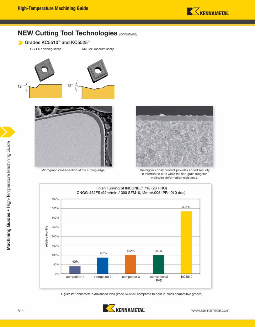
GG-FS finishing sharp MG-MS medium sharp
Micrograph cross-section of the cutting edge. The higher cobalt content provides added security
in interrupted cuts while the fine-grain tungsten
maintains deformation resistance.
Finish Turning of INCONEL® 718 (28 HRC)
CNGG-432FS (92m/min / 300 SFM–0,12mm/.005 IPR–.010 doc)
Figure 2: Kennametal’s advanced PVD grade KC5510 compared to best-in-class competitive grades.
rela
tive t
oo
l lif
e
competitor 1 competitor 2 competitor 3 conventional
PVDKC5510
NEW Cutting Tool Technologies (continued)
Grades KC5510™ and KC5525™
A14
High-Temperature Machining Guide
www.kennametal.com
Ma
ch
inin
g G
uid
es •
Hig
h-T
em
pera
ture
Machin
ing G
uid
e
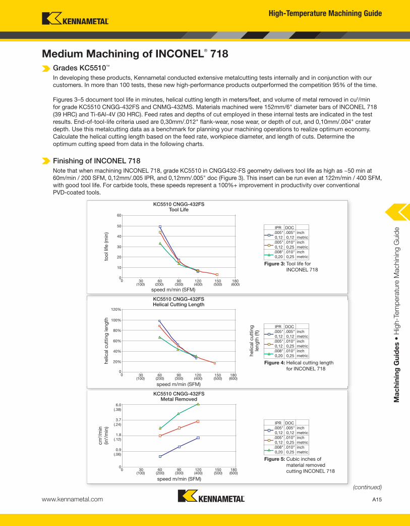
Medium Machining of INCONEL®
718
60
50
40
30
20
10
00 30 60 90 120 150 180
(100) (200) (300) (400) (500) (600)
Figure 3: Tool life for
INCONEL 718
Figure 5: Cubic inches of
material removed
cutting INCONEL 718
Figure 4: Helical cutting length
for INCONEL 718
too
l lif
e (m
in)
speed m/min (SFM)
KC5510 CNGG-432FSHelical Cutting Length
speed m/min (SFM)
KC5510 CNGG-432FSMetal Removed
Grades KC5510™
In developing these products, Kennametal conducted extensive metalcutting tests internally and in conjunction with our
customers. In more than 100 tests, these new high-performance products outperformed the competition 95% of the time.
Figures 3–5 document tool life in minutes, helical cutting length in meters/feet, and volume of metal removed in cu3/min
for grade KC5510 CNGG-432FS and CNMG-432MS. Materials machined were 152mm/6" diameter bars of INCONEL 718
(39 HRC) and Ti-6Al-4V (30 HRC). Feed rates and depths of cut employed in these internal tests are indicated in the test
results. End-of-tool-life criteria used are 0,30mm/.012" flank-wear, nose wear, or depth of cut, and 0,10mm/.004" crater
depth. Use this metalcutting data as a benchmark for planning your machining operations to realize optimum economy.
Calculate the helical cutting length based on the feed rate, workpiece diameter, and length of cuts. Determine the
optimum cutting speed from data in the following charts.
Finishing of INCONEL 718
Note that when machining INCONEL 718, grade KC5510 in CNGG432-FS geometry delivers tool life as high as ~50 min at
60m/min / 200 SFM, 0,12mm/.005 IPR, and 0,12mm/.005" doc (Figure 3). This insert can be run even at 122m/min / 400 SFM,
with good tool life. For carbide tools, these speeds represent a 100%+ improvement in productivity over conventional
PVD-coated tools.
A15
(continued)
KC5510 CNGG-432FSTool Life
speed m/min (SFM)
IPR DOC
.005" .005" inch
0,12 0,12 metric
.005" .010" inch
0,12 0,25 metric
.008" .010" inch
0,20 0,25 metric
IPR DOC
.005" .005" inch
0,12 0,12 metric
.005" .010" inch
0,12 0,25 metric
.008" .010" inch
0,20 0,25 metric
IPR DOC
.005" .005" inch
0,12 0,12 metric
.005" .010" inch
0,12 0,25 metric
.008" .010" inch
0,20 0,25 metric
helic
al cutt
ing
le
ng
th (ft
)
helic
al cutt
ing
leng
thcm
3/m
in
(in
3/m
in)
High-Temperature Machining Guide
www.kennametal.com
Ma
ch
inin
g G
uid
es •
Hig
h-T
em
pera
ture
Machin
ing G
uid
e
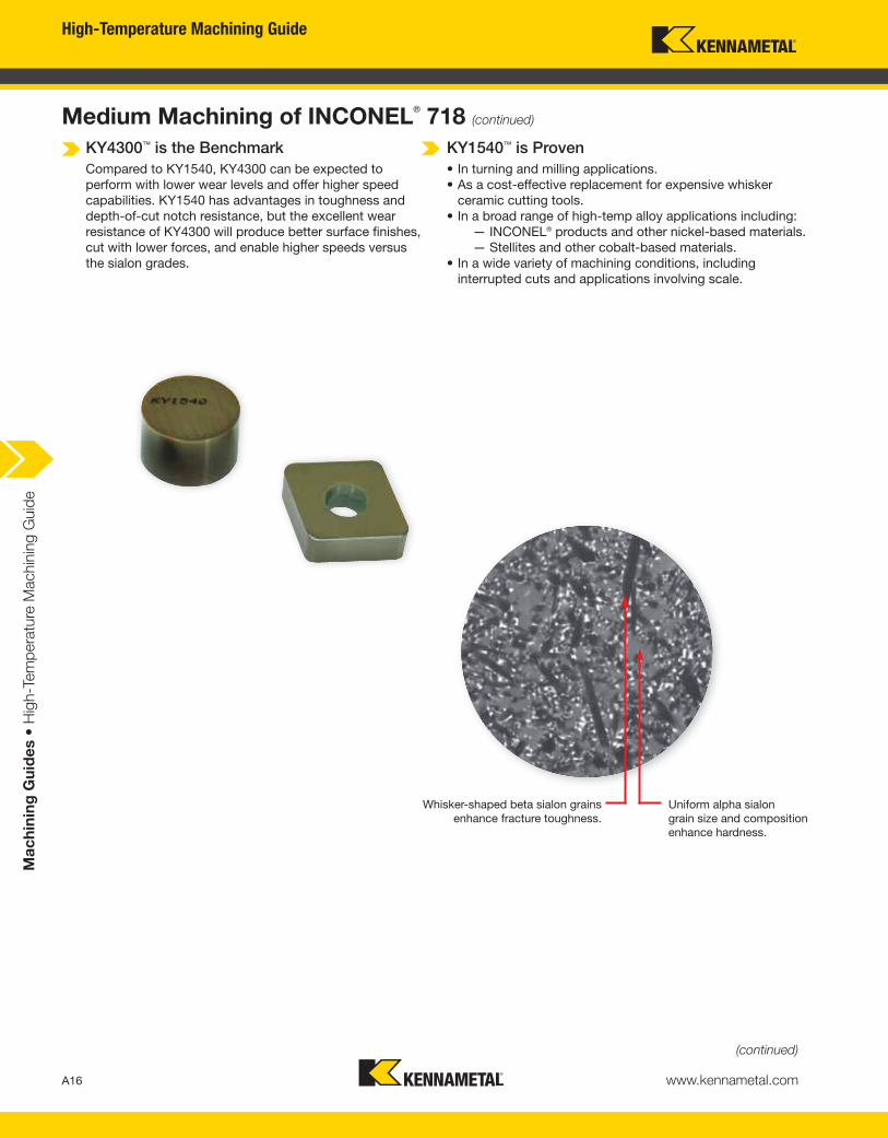
Whisker-shaped beta sialon grains
enhance fracture toughness.Uniform alpha sialon
grain size and composition
enhance hardness.
KY4300™ is the Benchmark
Compared to KY1540, KY4300 can be expected to
perform with lower wear levels and offer higher speed
capabilities. KY1540 has advantages in toughness and
depth-of-cut notch resistance, but the excellent wear
resistance of KY4300 will produce better surface finishes,
cut with lower forces, and enable higher speeds versus
the sialon grades.
KY1540™ is Proven
• In turning and milling applications.
• As a cost-effective replacement for expensive whisker
ceramic cutting tools.
• In a broad range of high-temp alloy applications including:
— INCONEL® products and other nickel-based materials.
— Stellites and other cobalt-based materials.
• In a wide variety of machining conditions, including
interrupted cuts and applications involving scale.
A16
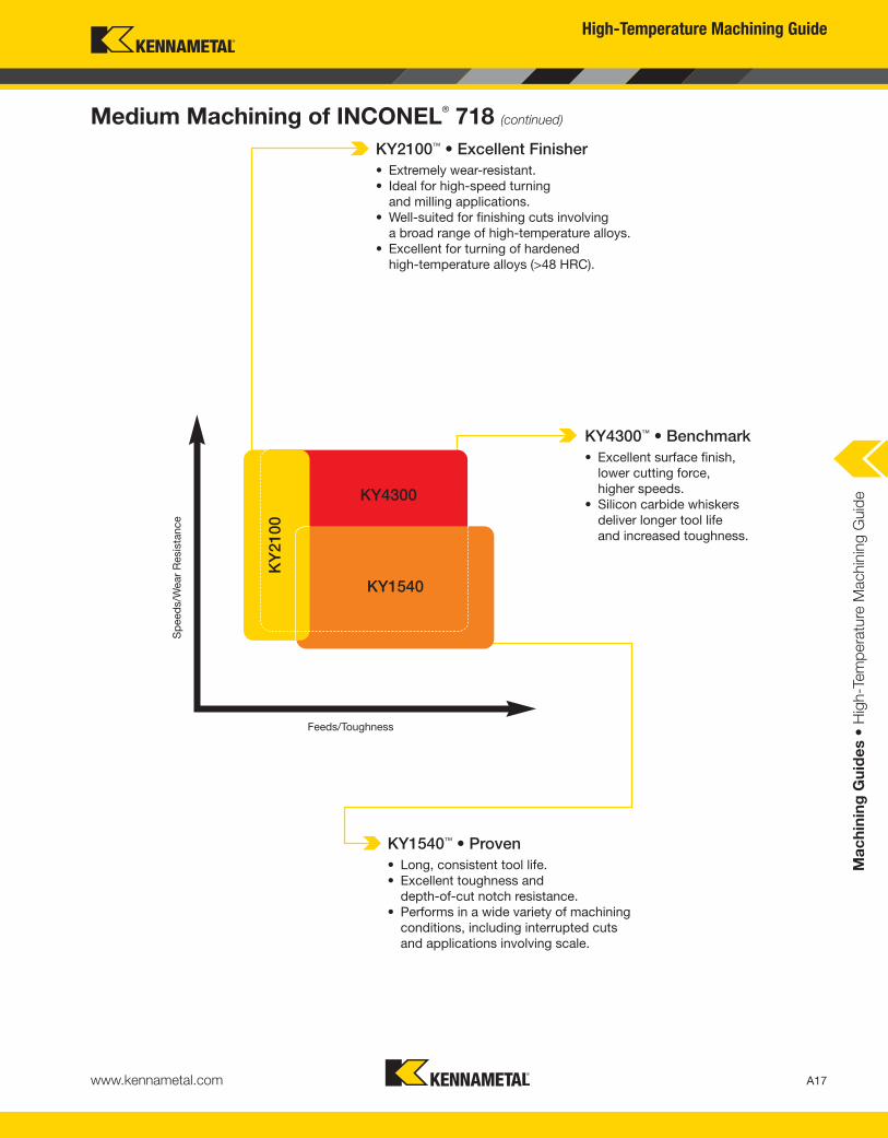
Medium Machining of INCONEL®
718 (continued)
(continued)
High-Temperature Machining Guide
www.kennametal.com
Ma
ch
inin
g G
uid
es •
Hig
h-T
em
pera
ture
Machin
ing G
uid
e
KY2100™ • Excellent Finisher
• Extremely wear-resistant.
• Ideal for high-speed turning
and milling applications.
• Well-suited for finishing cuts involving
a broad range of high-temperature alloys.
• Excellent for turning of hardened
high-temperature alloys (>48 HRC).
KY4300™ • Benchmark
• Excellent surface finish,
lower cutting force,
higher speeds.
• Silicon carbide whiskers
deliver longer tool life
and increased toughness.
KY1540™ • Proven
• Long, consistent tool life.
• Excellent toughness and
depth-of-cut notch resistance.
• Performs in a wide variety of machining
conditions, including interrupted cuts
and applications involving scale.
Feeds/Toughness
Sp
eed
s/W
ear
Resis
tance
A17
Medium Machining of INCONEL®
718 (continued)
KY4300
KY1540
KY
2100


![EXT-T24-D201 LCD Temperature Controller - …V1.2_22_9_2017].pdf · EXT-T24-D201 LCD Temperature Controller ... LCD temperature controller EXT-T24-D201 provides the foundation for](https://static.fdocument.org/doc/165x107/5a80a5287f8b9a0c748c8809/ext-t24-d201-lcd-temperature-controller-v122292017pdfext-t24-d201-lcd.jpg)