AE 451 Aeronautical Engineering Design Iae451/lecture11_aerodynamics.pdf · AE 451 Aeronautical...
59
AE 451 Aeronautical Engineering Design I Aerodynamics Prof. Dr. Serkan Özgen Dept. Aerospace Engineering December 2017
Transcript of AE 451 Aeronautical Engineering Design Iae451/lecture11_aerodynamics.pdf · AE 451 Aeronautical...

AE 451 Aeronautical Engineering Design IAerodynamics
Prof. Dr. Serkan Özgen
Dept. Aerospace Engineering
December 2017
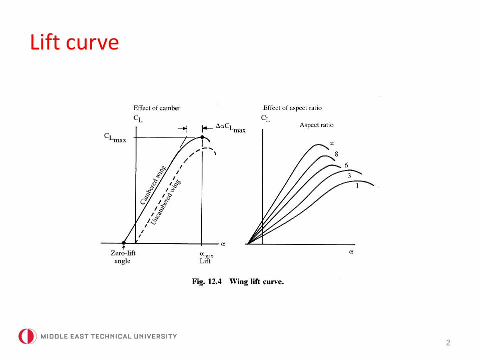
Lift curve
2
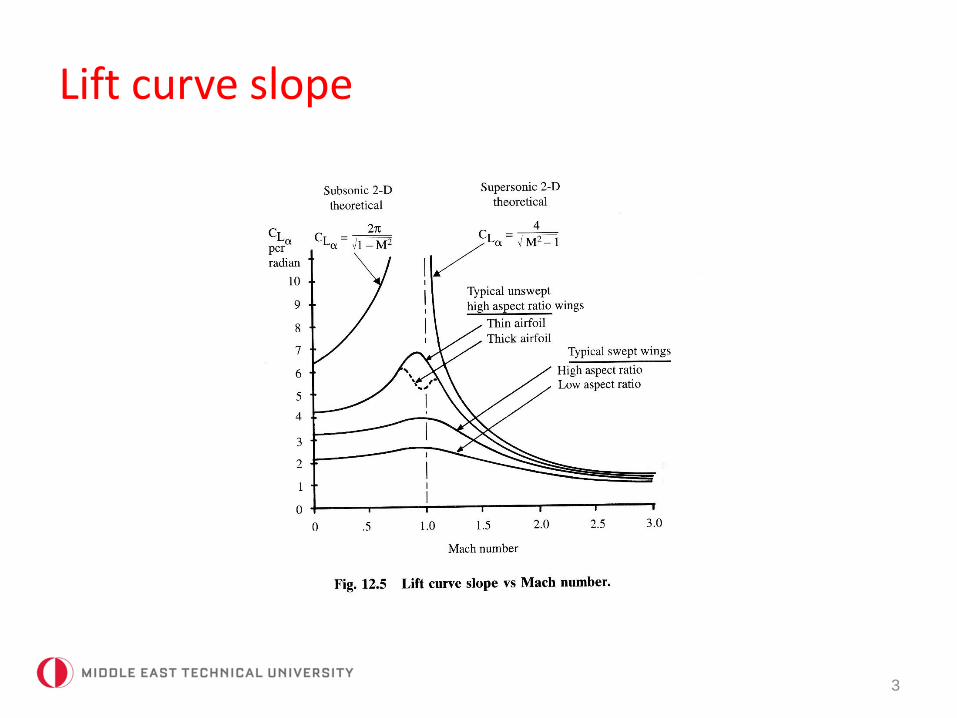
Lift curve slope
3
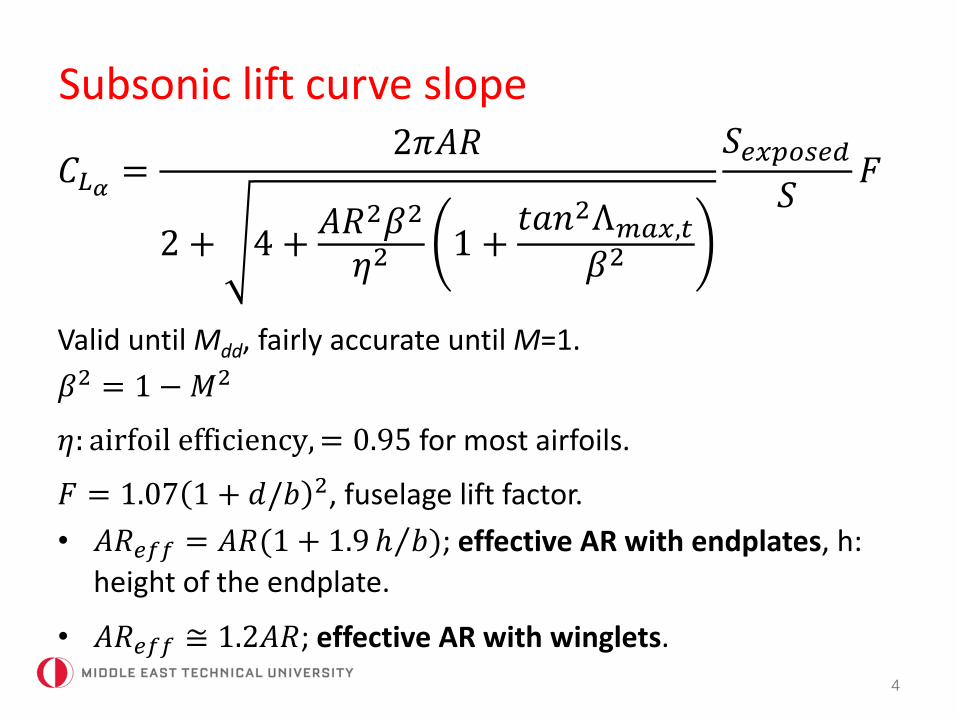
Subsonic lift curve slope
4
𝐶𝐿𝛼 =2𝜋𝐴𝑅
2 + 4 +𝐴𝑅2𝛽2
𝜂21 +
𝑡𝑎𝑛2Λ𝑚𝑎𝑥,𝑡
𝛽2
𝑆𝑒𝑥𝑝𝑜𝑠𝑒𝑑
𝑆𝐹
Valid until Mdd, fairly accurate until M=1.
𝛽2 = 1 −𝑀2
𝜂: airfoil efficiency,= 0.95 for most airfoils.
𝐹 = 1.07 1 + 𝑑/𝑏 2, fuselage lift factor.
• 𝐴𝑅𝑒𝑓𝑓 = 𝐴𝑅(1 + 1.9 ℎ 𝑏); effective AR with endplates, h:
height of the endplate.
• 𝐴𝑅𝑒𝑓𝑓 ≅ 1.2𝐴𝑅; effective AR with winglets.
Supersonic lift curve slope
5
• Theory: 𝐶𝐿𝛼 =4
𝛽
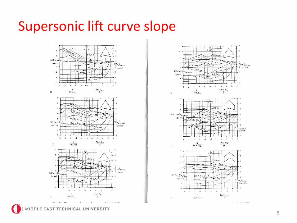
• Practice: use the charts valid for trapezoidal wings.
• Correct the values read with𝑆𝑒𝑥𝑝𝑜𝑠𝑒𝑑
𝑆𝐹
Supersonic lift curve slope
6
Maximum lift (clean)
7
• For moderate to high aspect ratio wings with moderatesweep and high leading edge radius:
𝐶𝐿,𝑚𝑎𝑥 = 0.9𝑐𝑙,𝑚𝑎𝑥𝑐𝑜𝑠Λ𝑐/4
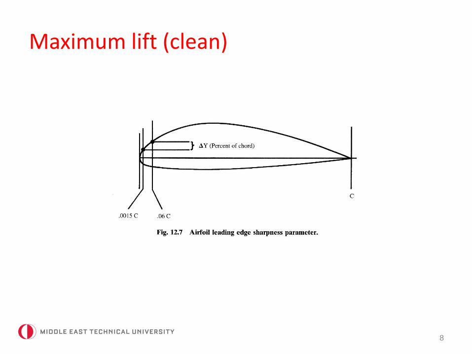
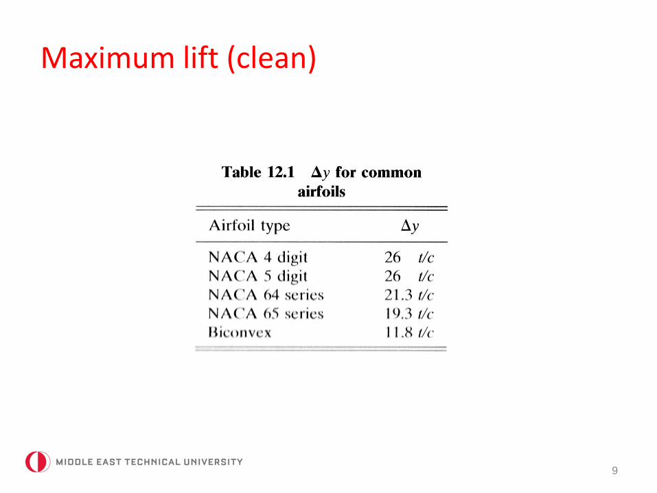
• If a wing has low AR or high sweep and a sharp leading edge, maximum lift will increase due to leading edge vortices. Thisis a function of the shape of the upper surface of the leadingedge:
∆𝑦 = 𝑦0.06𝑐 − 𝑦0.015𝑐
Maximum lift (clean)
8
Maximum lift (clean)
9
Maximum lift (clean)
10
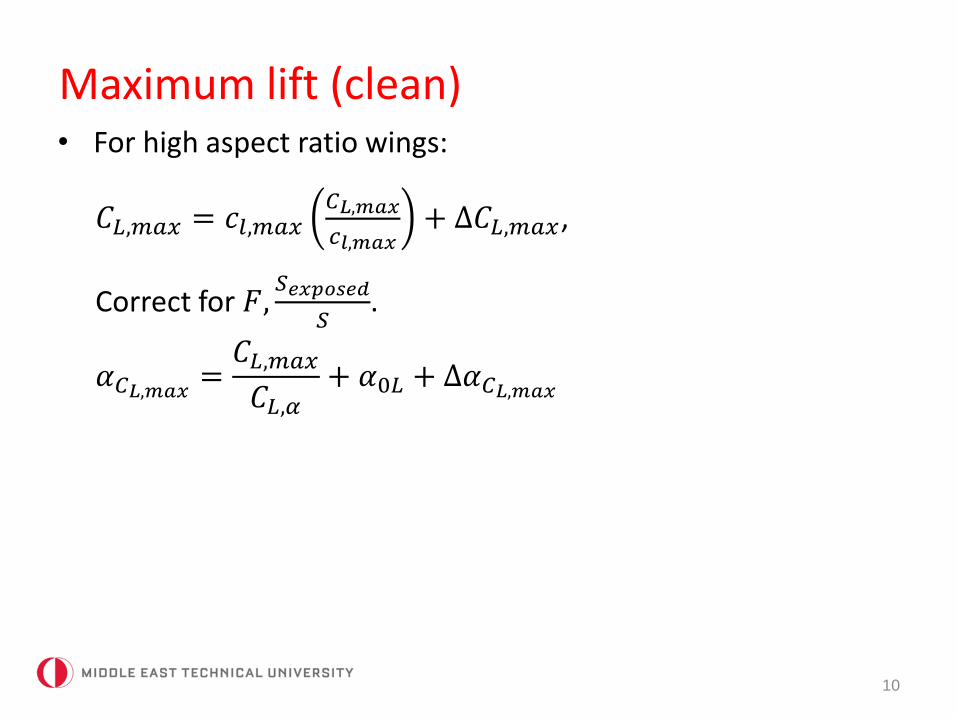
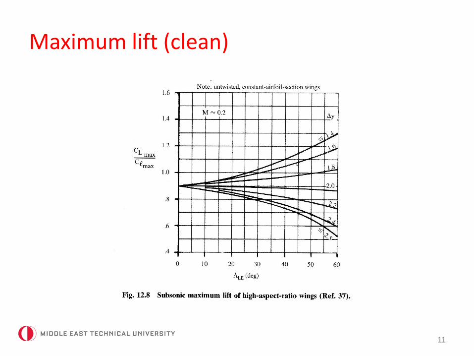
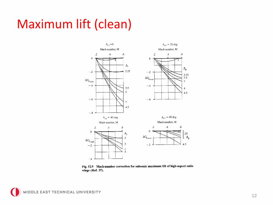
• For high aspect ratio wings:
𝐶𝐿,𝑚𝑎𝑥 = 𝑐𝑙,𝑚𝑎𝑥𝐶𝐿,𝑚𝑎𝑥
𝑐𝑙,𝑚𝑎𝑥+ ∆𝐶𝐿,𝑚𝑎𝑥,
Correct for 𝐹,𝑆𝑒𝑥𝑝𝑜𝑠𝑒𝑑
𝑆.
𝛼𝐶𝐿,𝑚𝑎𝑥=𝐶𝐿,𝑚𝑎𝑥
𝐶𝐿,𝛼+ 𝛼0𝐿 + ∆𝛼𝐶𝐿,𝑚𝑎𝑥
Maximum lift (clean)
11
Maximum lift (clean)
12
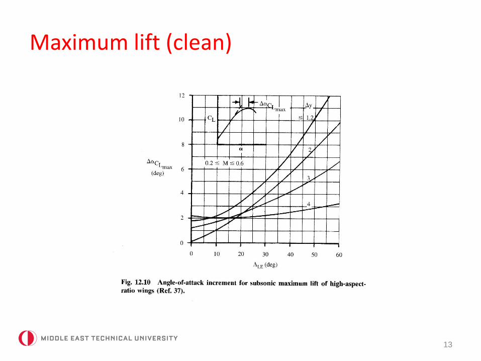
Maximum lift (clean)
13
Maximum lift (clean)
14
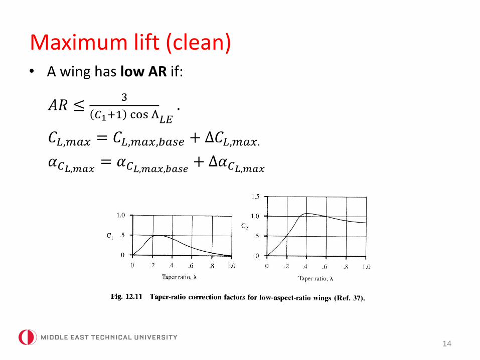
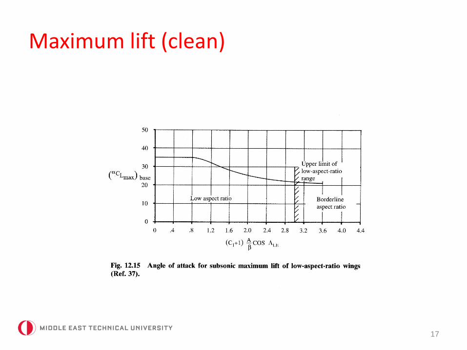
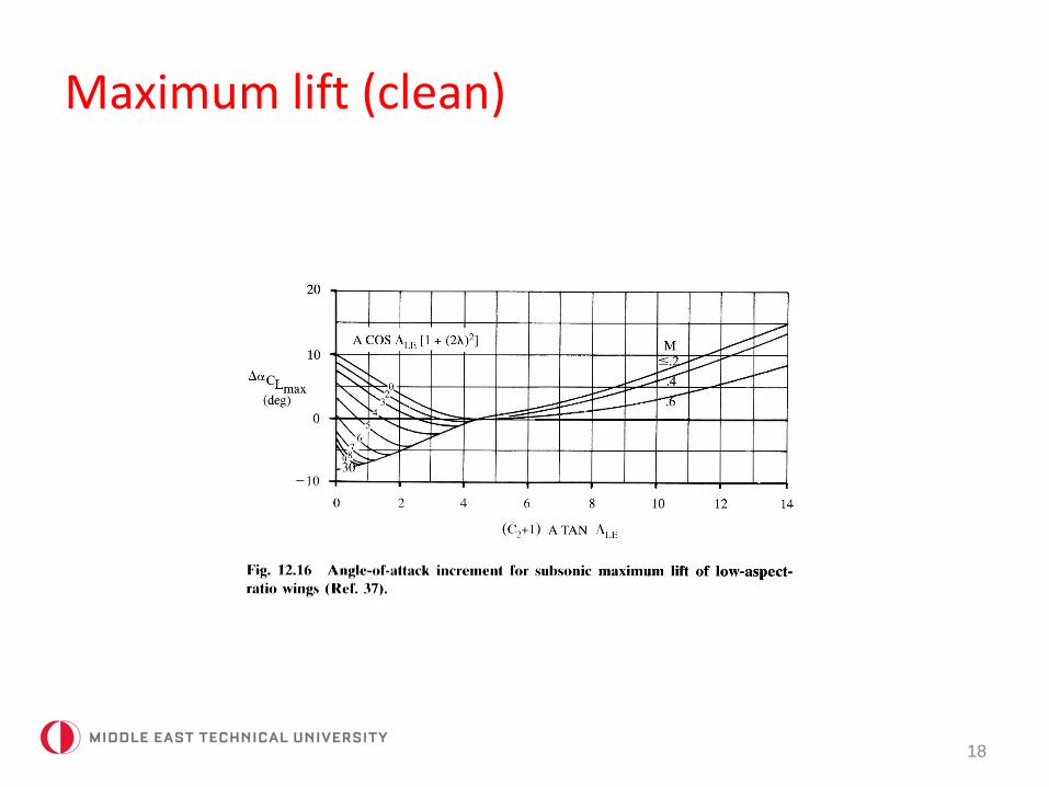
• A wing has low AR if:
𝐴𝑅 ≤3
𝐶1+1 cos Λ𝐿𝐸.
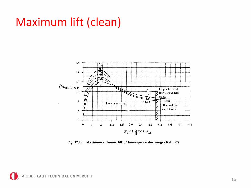
𝐶𝐿,𝑚𝑎𝑥 = 𝐶𝐿,𝑚𝑎𝑥,𝑏𝑎𝑠𝑒 + ∆𝐶𝐿,𝑚𝑎𝑥.
𝛼𝐶𝐿,𝑚𝑎𝑥= 𝛼𝐶𝐿,𝑚𝑎𝑥,𝑏𝑎𝑠𝑒
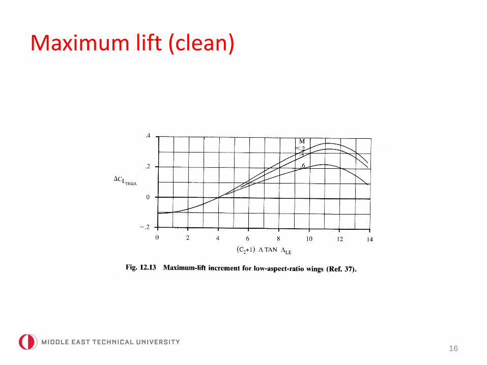
+ ∆𝛼𝐶𝐿,𝑚𝑎𝑥
Maximum lift (clean)
15
Maximum lift (clean)
16
Maximum lift (clean)
17
Maximum lift (clean)
18
Maximum lift (clean)
19
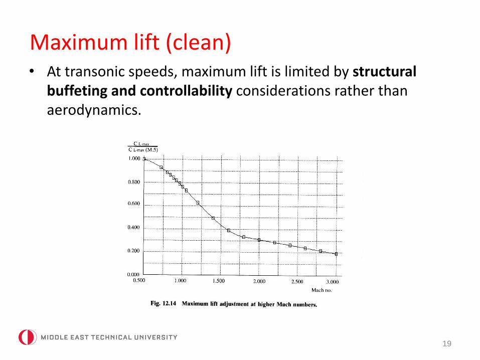
• At transonic speeds, maximum lift is limited by structuralbuffeting and controllability considerations rather thanaerodynamics.
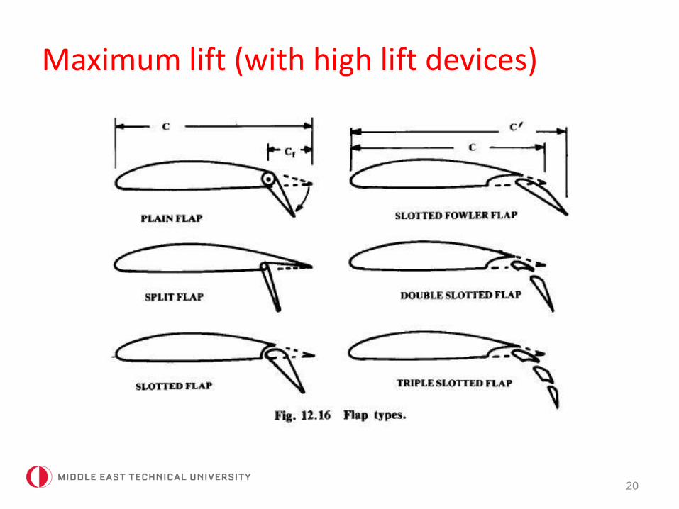
Maximum lift (with high lift devices)
20
Maximum lift (with high lift devices)
21
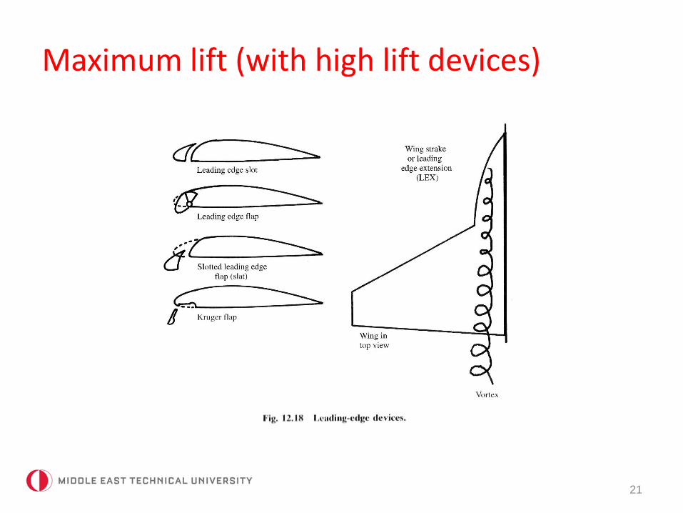
Maximum lift (with high lift devices)
22
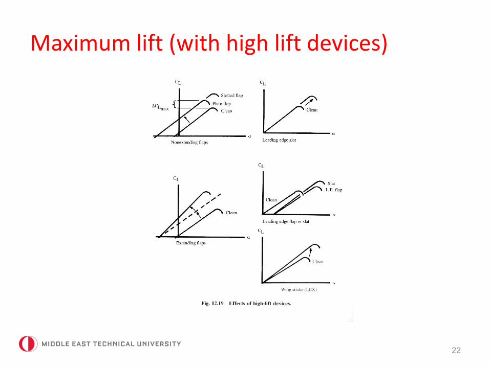
Maximum lift (with high lift devices)
23
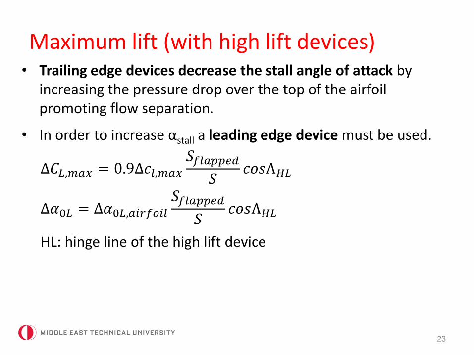
• Trailing edge devices decrease the stall angle of attack byincreasing the pressure drop over the top of the airfoilpromoting flow separation.
• In order to increase αstall a leading edge device must be used.
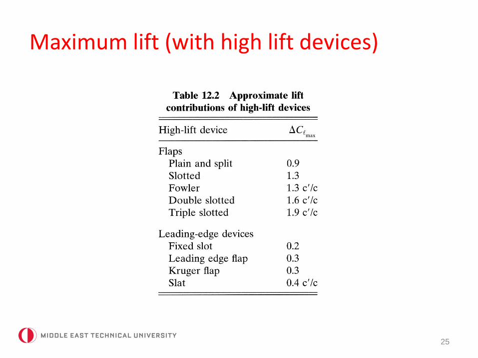
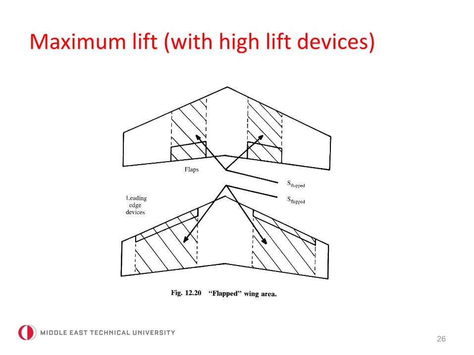
∆𝐶𝐿,𝑚𝑎𝑥 = 0.9∆𝑐𝑙,𝑚𝑎𝑥
𝑆𝑓𝑙𝑎𝑝𝑝𝑒𝑑𝑆
𝑐𝑜𝑠Λ𝐻𝐿
∆𝛼0𝐿 = ∆𝛼0𝐿,𝑎𝑖𝑟𝑓𝑜𝑖𝑙𝑆𝑓𝑙𝑎𝑝𝑝𝑒𝑑
𝑆𝑐𝑜𝑠Λ𝐻𝐿
HL: hinge line of the high lift device
Maximum lift (with high lift devices)
24
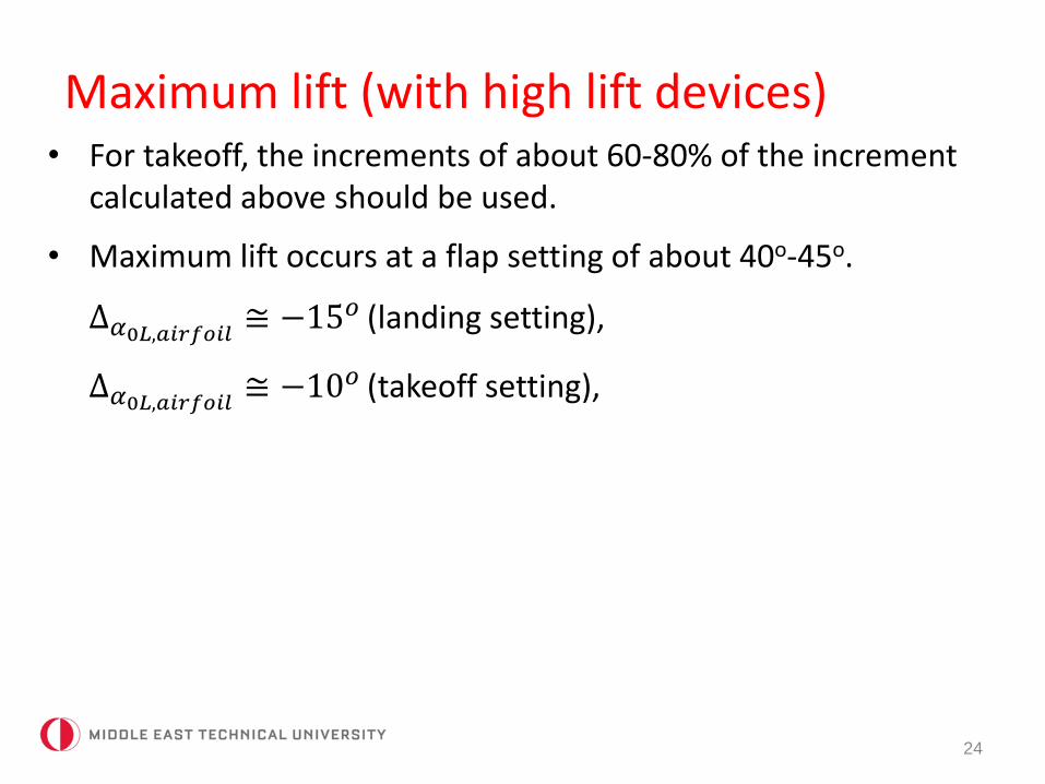
• For takeoff, the increments of about 60-80% of the incrementcalculated above should be used.
• Maximum lift occurs at a flap setting of about 40o-45o.
∆𝛼0𝐿,𝑎𝑖𝑟𝑓𝑜𝑖𝑙 ≅ −15𝑜 (landing setting),
∆𝛼0𝐿,𝑎𝑖𝑟𝑓𝑜𝑖𝑙 ≅ −10𝑜 (takeoff setting),
Maximum lift (with high lift devices)
25
Maximum lift (with high lift devices)
26
Maximum lift (with high lift devices)
27
• Leading edge devices increase lift by:
– Increasing camber,
– Increasing wing area,
– Delaying separation.
• Leading edge devices are particularly useful at high α.
• During takeoff and landing, they are useful when in combinationwith trailing edge devices as they prevent stall.
Estimation of CDo, equivalent skin friction method
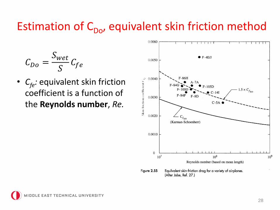
𝐶𝐷𝑜 =𝑆𝑤𝑒𝑡𝑆
𝐶𝑓𝑒
• Cfe: equivalent skin frictioncoefficient is a function of the Reynolds number, Re.
28
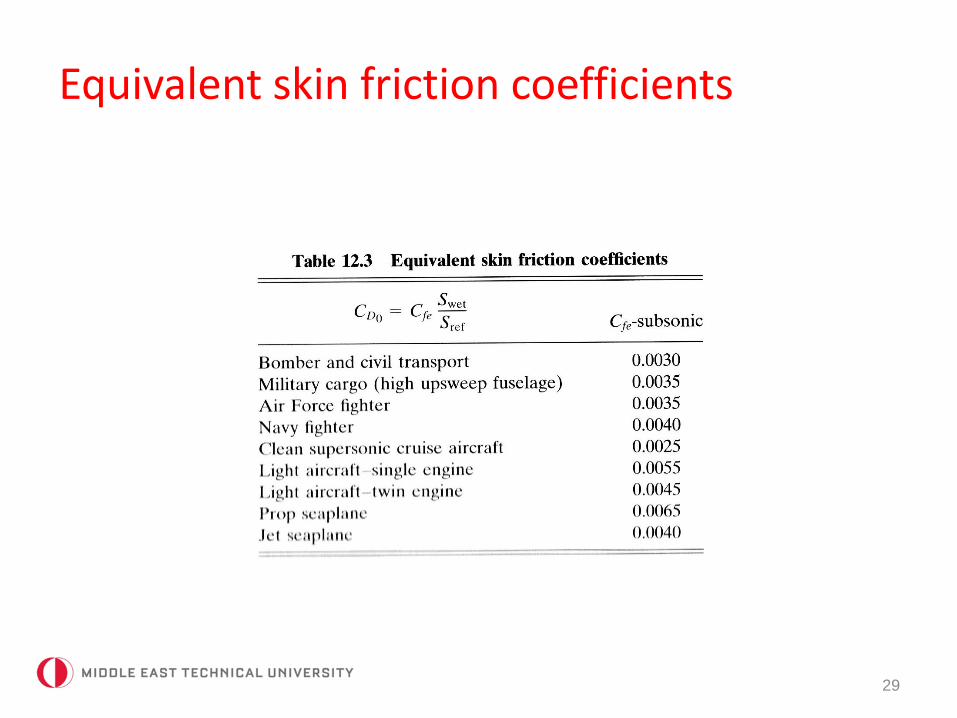
Equivalent skin friction coefficients
29
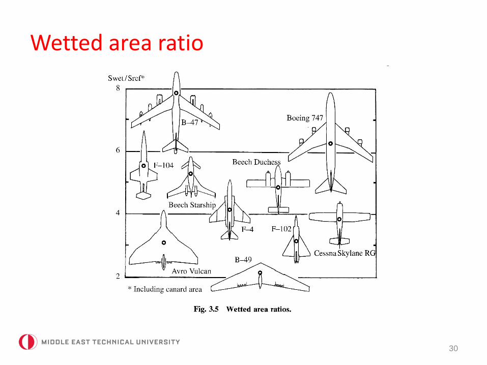
Wetted area ratio
30
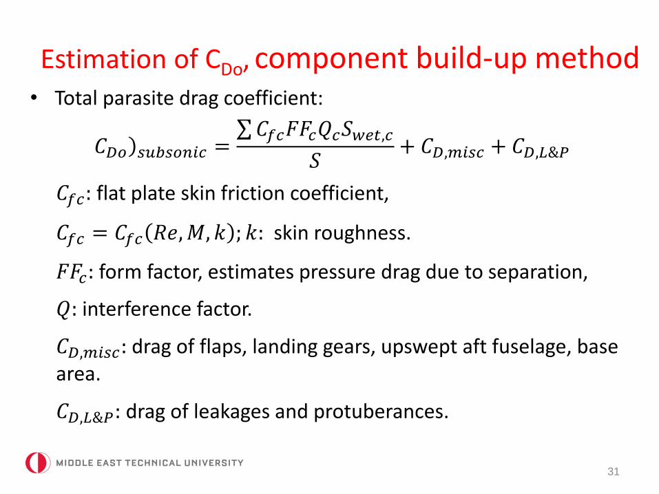
Estimation of CDo, component build-up method
31
• Total parasite drag coefficient:
)𝐶𝐷𝑜 𝑠𝑢𝑏𝑠𝑜𝑛𝑖𝑐 = 𝐶𝑓𝑐𝐹𝐹𝑐𝑄𝑐𝑆𝑤𝑒𝑡,𝑐
𝑆+ 𝐶𝐷,𝑚𝑖𝑠𝑐 + 𝐶𝐷,𝐿&𝑃
𝐶𝑓𝑐: flat plate skin friction coefficient,
𝐶𝑓𝑐 = 𝐶𝑓𝑐 𝑅𝑒,𝑀, 𝑘 ; 𝑘: skin roughness.
𝐹𝐹𝑐: form factor, estimates pressure drag due to separation,
𝑄: interference factor.
𝐶𝐷,𝑚𝑖𝑠𝑐: drag of flaps, landing gears, upswept aft fuselage, basearea.
𝐶𝐷,𝐿&𝑃: drag of leakages and protuberances.
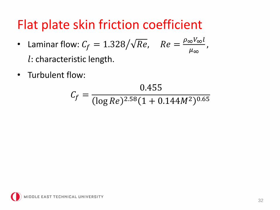
Flat plate skin friction coefficient
32
• Laminar flow: 𝐶𝑓 = 1.328 𝑅𝑒, 𝑅𝑒 =𝜌∞𝑉∞𝑙
𝜇∞,
𝑙: characteristic length.
• Turbulent flow:
𝐶𝑓 =0.455
log𝑅𝑒 2.58 1 + 0.144𝑀2 0.65
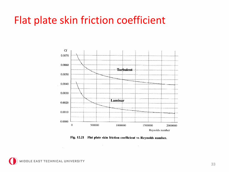
Flat plate skin friction coefficient
33
Flat plate skin friction coefficient
34
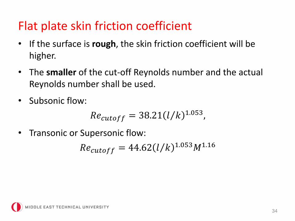
• If the surface is rough, the skin friction coefficient will be higher.
• The smaller of the cut-off Reynolds number and the actualReynolds number shall be used.
• Subsonic flow:
𝑅𝑒𝑐𝑢𝑡𝑜𝑓𝑓 = 38.21 𝑙 𝑘 1.053,
• Transonic or Supersonic flow:
𝑅𝑒𝑐𝑢𝑡𝑜𝑓𝑓 = 44.62 𝑙 𝑘 1.053𝑀1.16

Flat plate skin friction coefficient
35
Component form factors
36
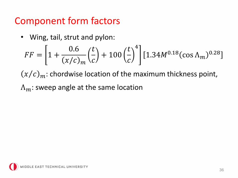
• Wing, tail, strut and pylon:
𝐹𝐹 = 1 +0.6
𝑥/𝑐 𝑚
𝑡
𝑐+ 100
𝑡
𝑐
4
1.34𝑀0.18 cos Λ𝑚0.28
𝑥 𝑐 𝑚: chordwise location of the maximum thickness point,
Λ𝑚: sweep angle at the same location
Component form factors
37
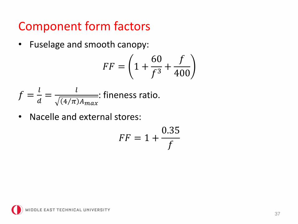
• Fuselage and smooth canopy:
𝐹𝐹 = 1 +60
𝑓3+
𝑓
400
𝑓 =𝑙
𝑑=
𝑙
4 𝜋 𝐴𝑚𝑎𝑥: fineness ratio.
• Nacelle and external stores:
𝐹𝐹 = 1 +0.35
𝑓
Component form factors
38
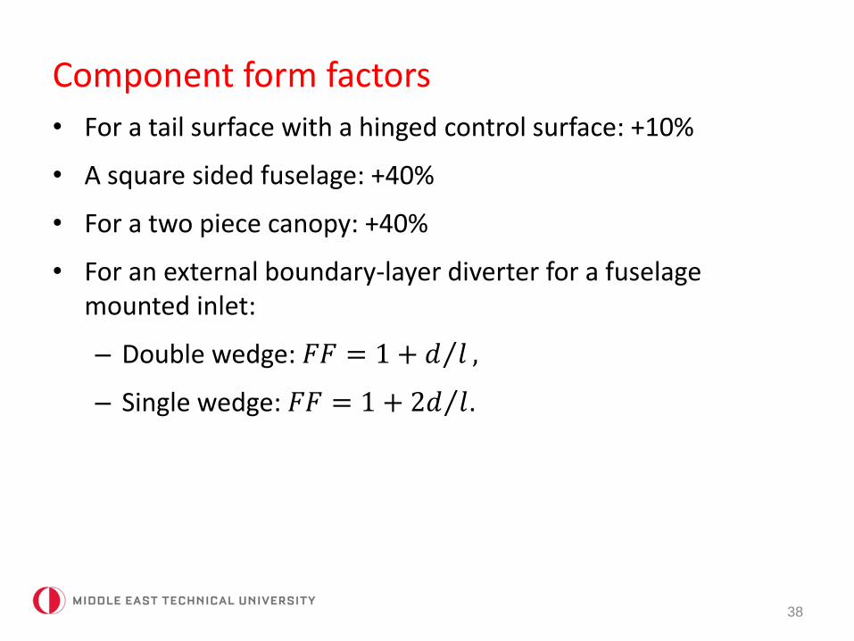
• For a tail surface with a hinged control surface: +10%
• A square sided fuselage: +40%
• For a two piece canopy: +40%
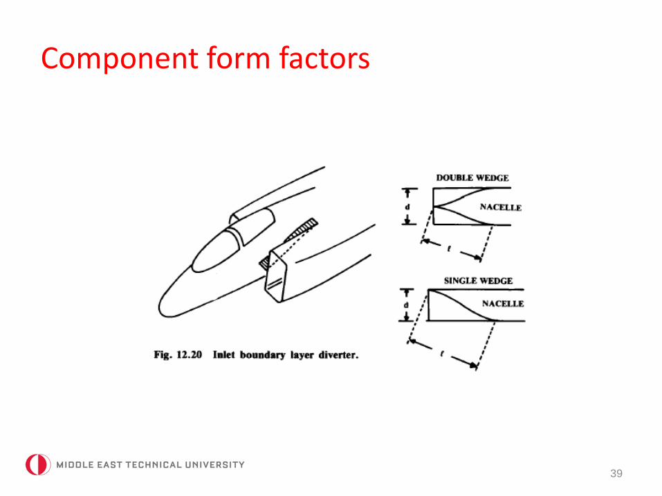
• For an external boundary-layer diverter for a fuselagemounted inlet:
– Double wedge: 𝐹𝐹 = 1 + 𝑑 𝑙 ,
– Single wedge: 𝐹𝐹 = 1 + 2𝑑 𝑙.
Component form factors
39
Component interference factors
40
• Nacelle or external store mounted on wing or fuselage: Q=1.5.
• Nacelle or external store mounted on wing or fuselage: Q=1.3 (if mounted less than one diameter away).
• Nacelle or external store mounted on wing or fuselage: Q=1.1 (if mounted more than one diameter away).
• Wingtip mounted missiles: Q=1.25.
• High-wing, mid-wing or a well-filleted low-wing: Q=1.0.
• Unfilleted low-wing: Q=1.1-1.4.
• Fuselage: Q=1.0.
• Tail surfaces: Q=1.03 (V-tail), 1.08 (H-Tail), 1.04-1.05 (conventional tail).
Miscellaneous drag
41
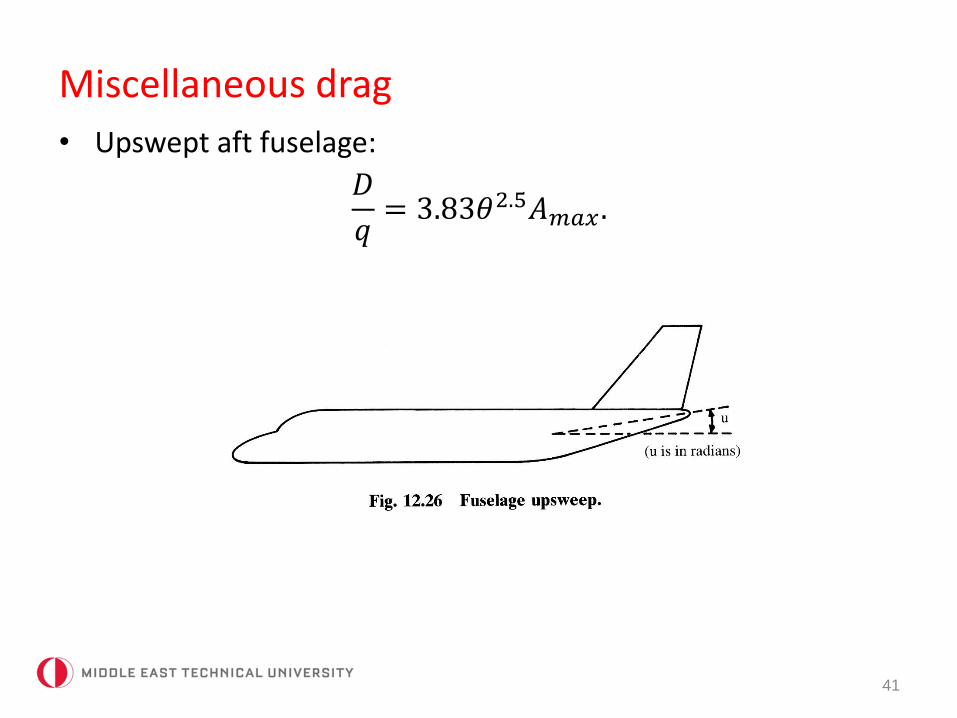
• Upswept aft fuselage:
𝐷
𝑞= 3.83𝜃2.5𝐴𝑚𝑎𝑥 .
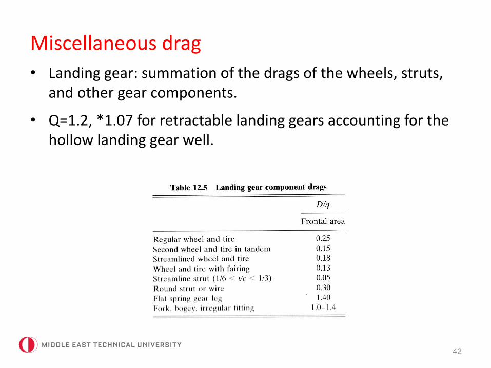
Miscellaneous drag
42
• Landing gear: summation of the drags of the wheels, struts, and other gear components.
• Q=1.2, *1.07 for retractable landing gears accounting for thehollow landing gear well.
Miscellaneous drag
43
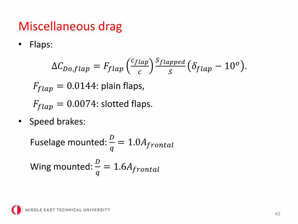
• Flaps:
∆𝐶𝐷𝑜,𝑓𝑙𝑎𝑝 = 𝐹𝑓𝑙𝑎𝑝𝑐𝑓𝑙𝑎𝑝
𝑐
𝑆𝑓𝑙𝑎𝑝𝑝𝑒𝑑
𝑆𝛿𝑓𝑙𝑎𝑝 − 10𝑜 .
𝐹𝑓𝑙𝑎𝑝 = 0.0144: plain flaps,
𝐹𝑓𝑙𝑎𝑝 = 0.0074: slotted flaps.
• Speed brakes:
Fuselage mounted: 𝐷
𝑞= 1.0𝐴𝑓𝑟𝑜𝑛𝑡𝑎𝑙
Wing mounted: 𝐷
𝑞= 1.6𝐴𝑓𝑟𝑜𝑛𝑡𝑎𝑙
Miscellaneous drag
44
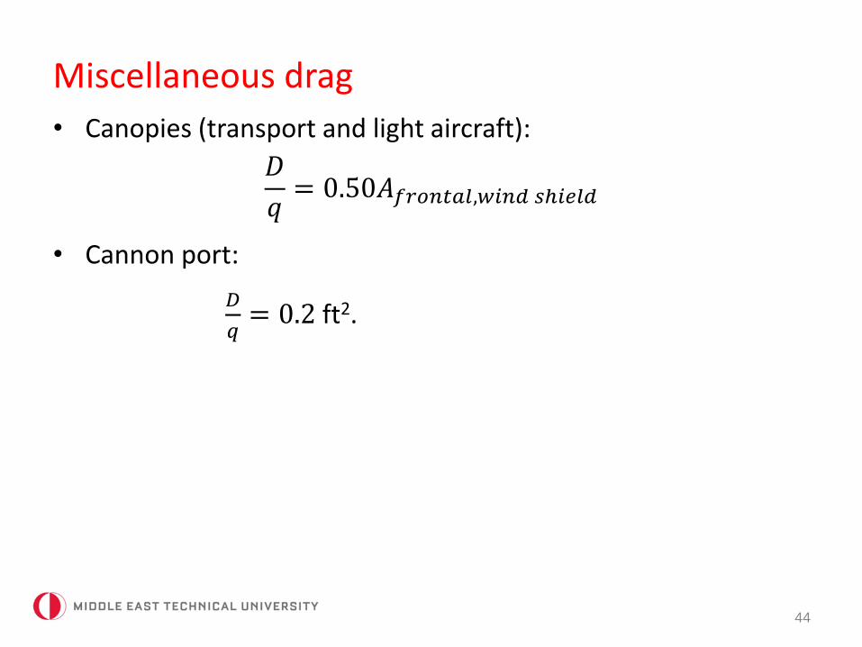
• Canopies (transport and light aircraft):
𝐷
𝑞= 0.50𝐴𝑓𝑟𝑜𝑛𝑡𝑎𝑙,𝑤𝑖𝑛𝑑 𝑠ℎ𝑖𝑒𝑙𝑑
• Cannon port:
𝐷
𝑞= 0.2 ft2.
Leakage and protuberance drag
45
• Antennas, lights, door edges, fuel vents, control surfaceexternal hinges, actuator fairings, rivets, rough or misalignedpanels…
• Jet transports and bombers: 2-5% parasite drag,
• Propeller aircraft: 5-10%,
• Fighters: 10-15% (old), 5-10% (new).
Supersonic Wave Drag
46
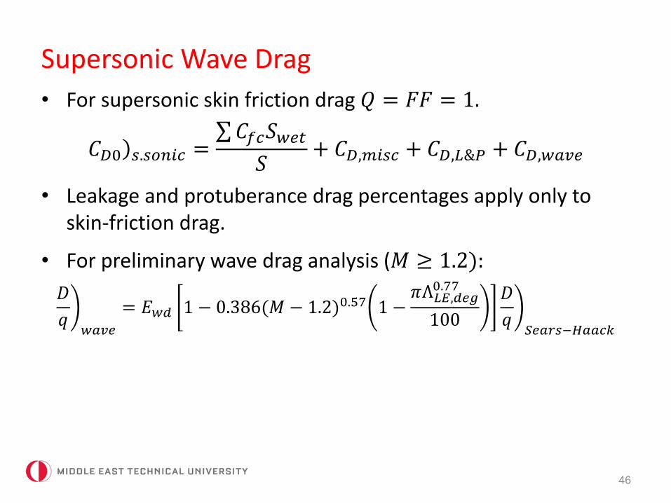
• For supersonic skin friction drag 𝑄 = 𝐹𝐹 = 1.
)𝐶𝐷0 𝑠.𝑠𝑜𝑛𝑖𝑐 = 𝐶𝑓𝑐𝑆𝑤𝑒𝑡
𝑆+ 𝐶𝐷,𝑚𝑖𝑠𝑐 + 𝐶𝐷,𝐿&𝑃 + 𝐶𝐷,𝑤𝑎𝑣𝑒
• Leakage and protuberance drag percentages apply only toskin-friction drag.
• For preliminary wave drag analysis (𝑀 ≥ 1.2):
𝐷
𝑞𝑤𝑎𝑣𝑒
= 𝐸𝑤𝑑 1 − 0.386(𝑀 − 1.2)0.57 1 −𝜋Λ𝐿𝐸,𝑑𝑒𝑔
0.77
100
𝐷
𝑞𝑆𝑒𝑎𝑟𝑠−𝐻𝑎𝑎𝑐𝑘
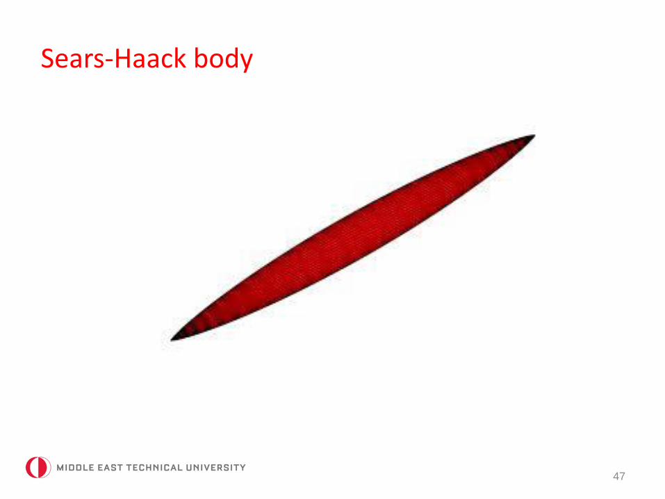
Sears-Haack body
47
Supersonic wave drag
48
• 𝐸𝑤𝑑: wave drag efficiency factor.
=1.0 for a perfect Sears-Haack body,
=1.2 for a smooth volume distribution, blended delta wing,
=1.8-2.2 for a supersonic fighter, bomber.
• 𝐷
𝑞 𝑆𝑒𝑎𝑟𝑠−𝐻𝑎𝑎𝑐𝑘=
9𝜋
2
𝐴𝑚𝑎𝑥
𝑙
2; subtract inlet capture area.
𝑙: aircraft length – length with constant cross sectional area.
Transonic wave drag
49
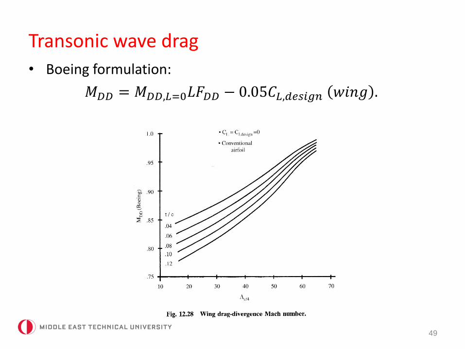
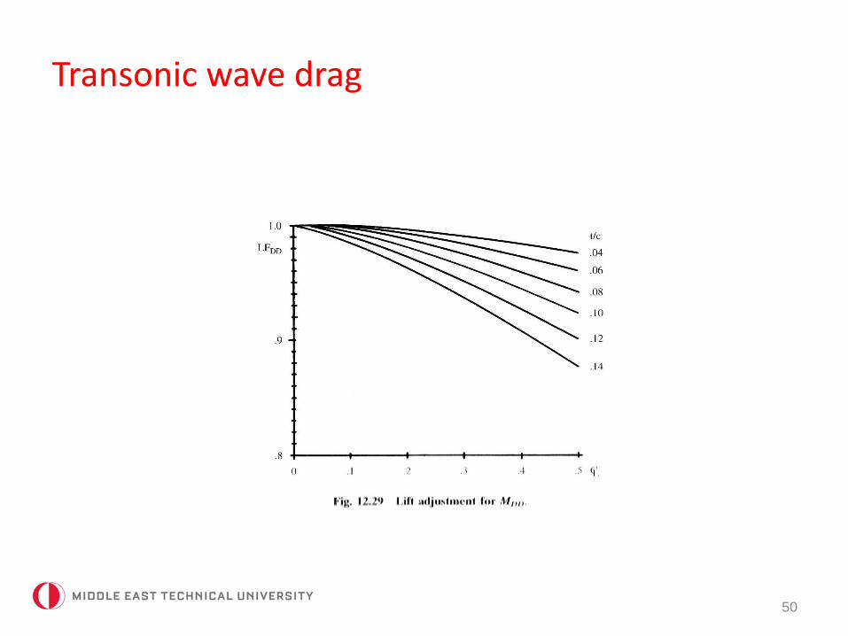
• Boeing formulation:
𝑀𝐷𝐷 = 𝑀𝐷𝐷,𝐿=0𝐿𝐹𝐷𝐷 − 0.05𝐶𝐿,𝑑𝑒𝑠𝑖𝑔𝑛 𝑤𝑖𝑛𝑔 .
Transonic wave drag
50

Transonic wave drag
51
Transonic wave drag
52
𝐿𝑛: length of fuselage from nose to the location where fuselagecross section becomes constant.
𝑑: equivalent diameter of the fuselage there.
Choose the smaller of the 𝑀𝑑𝑑 found for wing and fuselage forthe drag divergence Mach number of the airplane.
Transonic wave drag
53
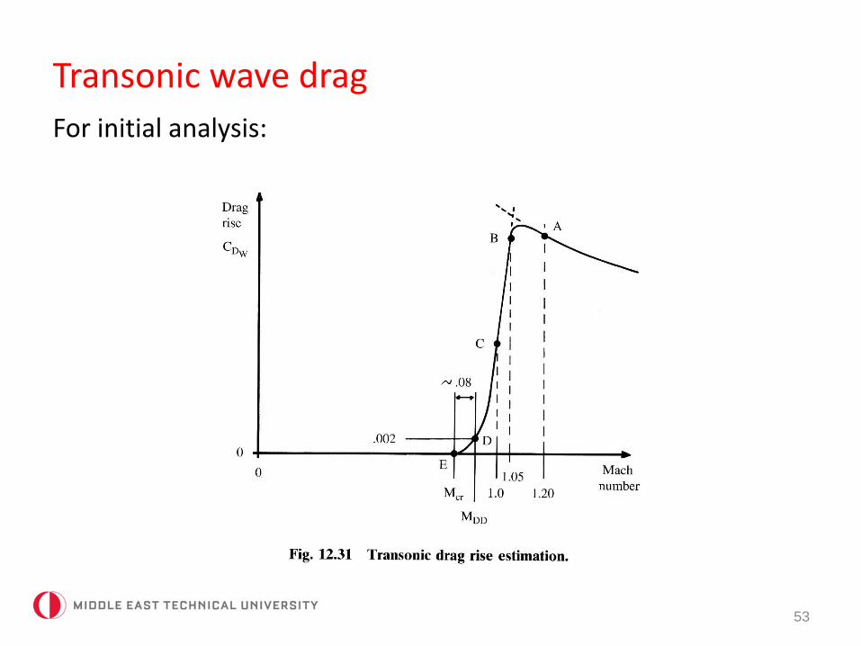
For initial analysis:
Transonic wave drag
54
• 𝑀 ≥ 1.2: use supersonic wave drag expression.
• 𝐶𝐷,𝑤𝑎𝑣𝑒 𝑀 = 1.05 = 𝐶𝐷,𝑤𝑎𝑣𝑒 𝑀 = 1.2 .
• 𝐶𝐷,𝑤𝑎𝑣𝑒 𝑀 = 1.0 =𝐶𝐷,𝑤𝑎𝑣𝑒 𝑀=1.05
2.
• 𝑀𝑐𝑟 = 𝑀𝐷𝐷 − 0.08.
• 𝐶𝐷 𝑀𝐷𝐷 = 𝐶𝐷 𝑀𝑐𝑟 + 0.002.
Complete drag build-up
55
• Subsonic drag: skin friction drag (including form factor andinterference) + miscellaneous drag + leakage & protuberancedrag
• Supersonic drag: skin friction drag + miscellaneous drag + leakage and protuberance drag + wave drag.
Complete drag build-up
56
Complete drag build-up
57
Drag due to lift (induced drag)
58
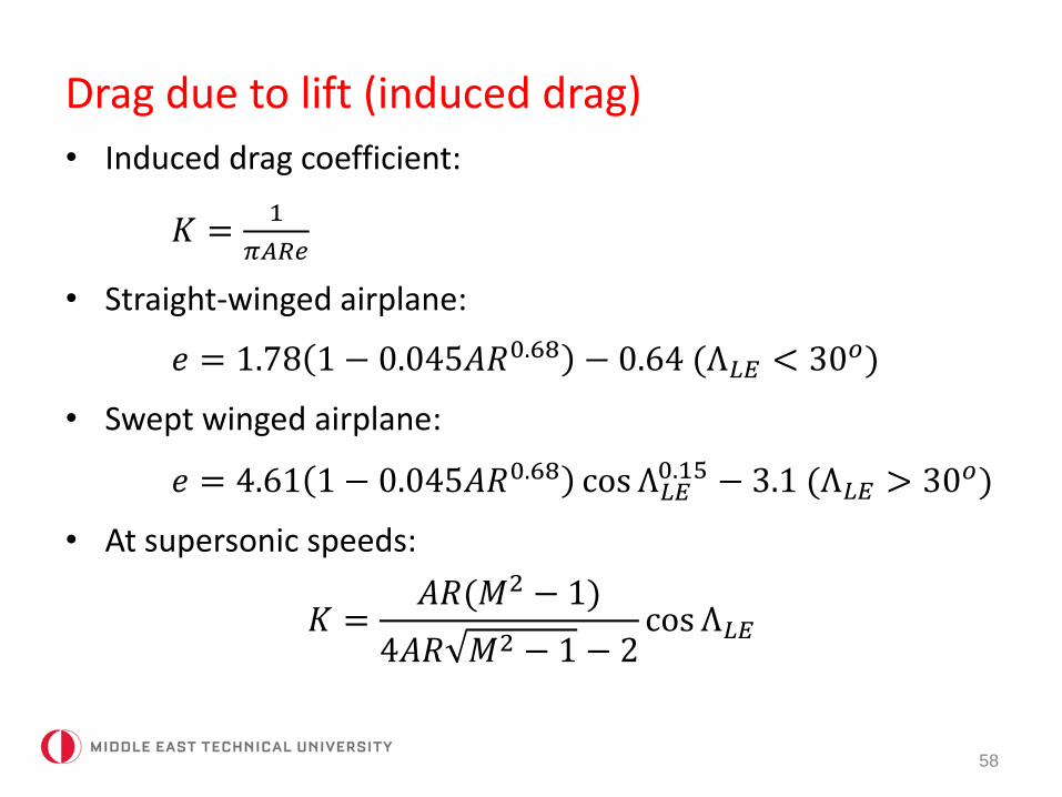
• Induced drag coefficient:
𝐾 =1
𝜋𝐴𝑅𝑒
• Straight-winged airplane:
𝑒 = 1.78 1 − 0.045𝐴𝑅0.68 − 0.64 (Λ𝐿𝐸 < 30𝑜)
• Swept winged airplane:
𝑒 = 4.61 1 − 0.045𝐴𝑅0.68 cos Λ𝐿𝐸0.15 − 3.1 (Λ𝐿𝐸 > 30𝑜)
• At supersonic speeds:
𝐾 =𝐴𝑅(𝑀2 − 1)
4𝐴𝑅 𝑀2 − 1 − 2cos Λ𝐿𝐸
Drag due to lift (induced drag)
59
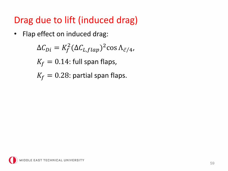
• Flap effect on induced drag:
∆𝐶𝐷𝑖 = 𝐾𝑓2(∆𝐶𝐿,𝑓𝑙𝑎𝑝)
2cos Λ 𝑐 4,
𝐾𝑓 = 0.14: full span flaps,
𝐾𝑓 = 0.28: partial span flaps.