Adaptive Tessellation for Trimmed NURBS Surface
8
Adaptive Tessellation for Trimmed NURBS Surface Ma YingLiang 1 and Terry Hewitt 2 Manchester Visualization Centre, University of Manchester, Manchester, M13 9PL, U.K. 1 [email protected] 2 [email protected] Abstract We present an adaptive method for tessellating the trimmed NURBS surface in the parametric domain. Given a model space tolerance ε, the algorithm first splits the NURBS surface in both the U and V directions to fit within the bounding box of the outer trimming loop. Then we subdivide the surface into Bézier patches recursively until the control net of the Bézier patch is flat enough and within the tolerance ε. By building up the quadtrees of inner trimming loops, we use the scanline algorithm to remove the patches inside the inner trimming loops. Finally, we close the inner trimming loops with a set of triangles. The resulting tessellation contains both quadrilaterals and triangles. 1. Introduction Trimmed surfaces have played a fundamental role in Computer Aided Design and Computer Graphics for many years. Most complex geometrical objects are generated from some sort of trimming process such as fillet, blend and chamfer operations. Trimmed surfaces are the result of a Boolean operation on the solid objects, which is bounded by a set of trimmed NURBS surfaces. Both in Computer Aided Design and Computer Graphics, the trimmed surfaces are tessellated into a set of triangles or quadrilaterals for the purpose of rendering for visualization, area computation and rapid prototyping. There are several tessellating methods which can be classified to two simple categories 1 : 1. Uniform subdivision. This is the simplest case and involves a user specifying a level which uniform subdivision of all patches is to terminate. 2. Non-uniform subdivision. This means stopping the division when the subdivision products meet a patch flatness criterion. The second category is theoretically preferable because it generates fewer polygons than the first one. Therefore, more subdivision takes place in the areas of high surface curvature. Most methods in the second category tessellate the trimmed NURBS surface in parameter space as parametric surfaces are widely used in the CAD/CAM domain. 2. The Definition of Trimmed NURBS Surface A trimmed NURBS surface consists of two things: (1) A NURBS surface. (2) A set of trimming curves lying within the parameter domain 2 . A NURBS surface of degree p in u direction and degree q in v direction is defined by: ) 1 ( ) ( ) ( ) ( ) ( ) , ( 0 0 , , , 0 , , 0 , , ∑∑ ∑∑ = = = = = n i m j j i q j p i n i j i j i m j q j p i w v N u N P w v N u N v u S Where the {P i,j } is the control net, 0≤u,v≤1, the {w i,j } are the weights, and N i,p (u) and N j,q (u) are non- rational B-spline basis functions defined on the knot vectors: { { } 1 ,..., 1 ,..., , 0 ,..., 0 { } 1 ,..., 1 , ,..., , 0 ,..., 0 { 1 , 1 1 1 1 1 1 1 + − − + + + − − + + = = q p s q q p p r p p v v V u u U 3 2 1 3 2 1 Where r = n + p + 1 and s = m + q + 1. The trimming curves are normally in NURBS form so that there will be uniform data structure to describe the whole trimmed surface. Assume that N such curves are given defined as ) 2 ( ,..., 2 , 1 ) ( )) ( ), ( ( ) ( , 0 N k t N P t v t u t C j i n i k i k k k = = = ∑ = These curves form a set of trimming loops: one outer loop and several inner loops. The outer loop
Transcript of Adaptive Tessellation for Trimmed NURBS Surface
Adaptive Tessellation for Trimmed NURBS Surface
Ma YingLiang 1 and Terry Hewitt2
Manchester Visualization Centre, University of Manchester, Manchester, M13 9PL, U.K.
[email protected] [email protected] Abstract We present an adaptive method for tessellating the trimmed NURBS surface in the parametric domain. Given a model space tolerance ε, the algorithm first splits the NURBS surface in both the U and V directions to fit within the bounding box of the outer trimming loop. Then we subdivide the surface into Bézier patches recursively until the control net of the Bézier patch is flat enough and within the tolerance ε. By building up the quadtrees of inner trimming loops, we use the scanline algorithm to remove the patches inside the inner trimming loops. Finally, we close the inner trimming loops with a set of triangles. The resulting tessellation contains both quadrilaterals and triangles. 1. Introduction Trimmed surfaces have played a fundamental role in Computer Aided Design and Computer Graphics for many years. Most complex geometrical objects are generated from some sort of trimming process such as fillet, blend and chamfer operations. Trimmed surfaces are the result of a Boolean operation on the solid objects, which is bounded by a set of trimmed NURBS surfaces. Both in Computer Aided Design and Computer Graphics, the trimmed surfaces are tessellated into a set of triangles or quadrilaterals for the purpose of rendering for visualization, area computation and rapid prototyping. There are several tessellating methods which can be classified to two simple categories 1:
1. Uniform subdivision. This is the simplest case and involves a user specifying a level which uniform subdivision of all patches is to terminate.
2. Non-uniform subdivision. This means stopping the division when the subdivision products meet a patch flatness criterion.
The second category is theoretically preferable because it generates fewer polygons than the first one. Therefore, more subdivision takes place in the areas of high surface curvature. Most methods in the second category tessellate the trimmed NURBS surface in parameter space as parametric surfaces are widely used in the CAD/CAM domain. 2. The Definition of Trimmed NURBS Surface
A trimmed NURBS surface consists of two things: (1) A NURBS surface. (2) A set of trimming curves lying within the parameter domain 2. A NURBS surface of degree p in u direction and degree q in v direction is defined by:
)1()()(
)()(),(
0 0,,,
0,,
0,,
∑∑
∑∑
= =
= == n
i
m
jjiqjpi
n
ijiji
m
jqjpi
wvNuN
PwvNuNvuS
Where the {Pi,j} is the control net, 0≤u,v≤1, the {wi,j} are the weights, and Ni,p(u) and Nj,q(u) are non-rational B-spline basis functions defined on the knot vectors:
{
{}1,...,1,...,,0,...,0{
}1,...,1,,...,,0,...,0{
1,11
1
111
1
+−−+
+
+−−+
+
=
=
qpsq
q
pprp
p
vvV
uuU
321
321
Where r = n + p + 1 and s = m + q + 1. The trimming curves are normally in NURBS form so that there will be uniform data structure to describe the whole trimmed surface. Assume that N such curves are given defined as
)2(,...,2,1
)())(),(()( ,0
Nk
tNPtvtutC ji
n
i
kikkk
=
== ∑=
These curves form a set of trimming loops: one outer loop and several inner loops. The outer loop
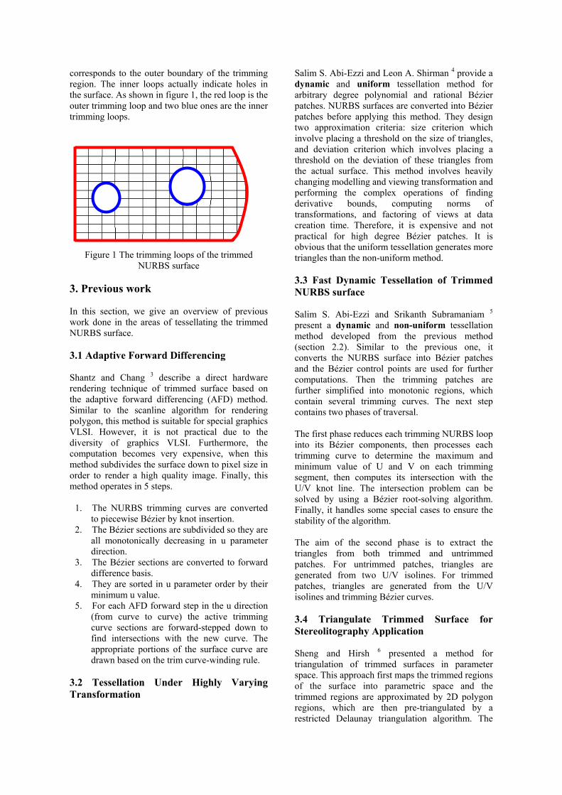
corresponds to the outer boundary of the trimming region. The inner loops actually indicate holes in the surface. As shown in figure 1, the red loop is the outer trimming loop and two blue ones are the inner trimming loops.
Figure 1 The trimming loops of the trimmed NURBS surface
3. Previous work In this section, we give an overview of previous work done in the areas of tessellating the trimmed NURBS surface. 3.1 Adaptive Forward Differencing Shantz and Chang 3 describe a direct hardware rendering technique of trimmed surface based on the adaptive forward differencing (AFD) method. Similar to the scanline algorithm for rendering polygon, this method is suitable for special graphics VLSI. However, it is not practical due to the diversity of graphics VLSI. Furthermore, the computation becomes very expensive, when this method subdivides the surface down to pixel size in order to render a high quality image. Finally, this method operates in 5 steps.
1. The NURBS trimming curves are converted to piecewise Bézier by knot insertion.
2. The Bézier sections are subdivided so they are all monotonically decreasing in u parameter direction.
3. The Bézier sections are converted to forward difference basis.
4. They are sorted in u parameter order by their minimum u value.
5. For each AFD forward step in the u direction (from curve to curve) the active trimming curve sections are forward-stepped down to find intersections with the new curve. The appropriate portions of the surface curve are drawn based on the trim curve-winding rule.
3.2 Tessellation Under Highly Varying Transformation
Salim S. Abi-Ezzi and Leon A. Shirman 4 provide a dynamic and uniform tessellation method for arbitrary degree polynomial and rational Bézier patches. NURBS surfaces are converted into Bézier patches before applying this method. They design two approximation criteria: size criterion which involve placing a threshold on the size of triangles, and deviation criterion which involves placing a threshold on the deviation of these triangles from the actual surface. This method involves heavily changing modelling and viewing transformation and performing the complex operations of finding derivative bounds, computing norms of transformations, and factoring of views at data creation time. Therefore, it is expensive and not practical for high degree Bézier patches. It is obvious that the uniform tessellation generates more triangles than the non-uniform method. 3.3 Fast Dynamic Tessellation of Trimmed NURBS surface Salim S. Abi-Ezzi and Srikanth Subramaniam 5 present a dynamic and non-uniform tessellation method developed from the previous method (section 2.2). Similar to the previous one, it converts the NURBS surface into Bézier patches and the Bézier control points are used for further computations. Then the trimming patches are further simplified into monotonic regions, which contain several trimming curves. The next step contains two phases of traversal. The first phase reduces each trimming NURBS loop into its Bézier components, then processes each trimming curve to determine the maximum and minimum value of U and V on each trimming segment, then computes its intersection with the U/V knot line. The intersection problem can be solved by using a Bézier root-solving algorithm. Finally, it handles some special cases to ensure the stability of the algorithm. The aim of the second phase is to extract the triangles from both trimmed and untrimmed patches. For untrimmed patches, triangles are generated from two U/V isolines. For trimmed patches, triangles are generated from the U/V isolines and trimming Bézier curves. 3.4 Triangulate Trimmed Surface for Stereolitography Application Sheng and Hirsh 6 presented a method for triangulation of trimmed surfaces in parameter space. This approach first maps the trimmed regions of the surface into parametric space and the trimmed regions are approximated by 2D polygon regions, which are then pre-triangulated by a restricted Delaunay triangulation algorithm. The
generated triangles are subdivided further until each edge of the triangles is smaller than the allowed length that results from the surface definition and the specified tolerance. The algorithm contains three steps:
1. Creation of mapping polygons. 2. Evaluation of the flatness of a patch 7. 3. Restricted Delaunay Triangulation.
3.5 Triangulating The Trimmed NURBS Surface in Parameter Domain Piegl and Richard 2 propose a somewhat similar algorithm to triangulate trimmed NURBS surfaces: They use the same criterion for maximum edge length, but the method does not split the surface into several regions representing Bézier patches in parameter space. This tessellation method consists of 5 steps: Step1 is to compute the longest edge size in the parameter domain 8. Step 2 obtains a polygonal approximation of trimming curves. Step 3 selects points inside the valid region. Step 4 triangulates the trimmed region. The final step is to map the triangles onto the surface and build a 3D triangular database for further processing. 3.6 Summary The first method is designed for the special graphic hardware for rendering triangles which are generated from the AFD method. It works for cubic Bézier surface only and it is not practical for tessellating the high degree surface. The second method is a uniform tessellation so that it will generate more triangles than non-uniform methods. The other three methods perform the tessellation in parametric space. The first method is both dynamic and non-uniform tessellation. However, it involves some complex algorithms which could reduce the stability of the whole method. The second method takes special care of the edges of the solid that is being subdivided, and guarantees the absence of cracks. This method has two main disadvantages: it is not adaptive (global bounds for second derivatives are found for every patch), and second, it does not care about the shape of the resulting triangles. The consequence of not being adaptive is that the number of required triangulation vertices is too large. The third method is adaptive and not sensitive to the complexity of the trimmed patch. Unlike the first method, it calculates the bound for second derivatives locally, therefore it achieve more efficient flatness testing. All three methods have common advantages and disadvantages as general tessellation methods in the parametric domain. Advantages:
• Methods that operate on triangles are far easier and numerically more stable than those dealing with freeform geometry.
• The piecewise triangular approximation is a parameter independent representation of the trimmed surface.
Disadvantages: • Adequate representation of a trimmed patch
with high curvature areas requires large numbers of triangles.
• The triangulation, if not done properly, can result in triangles of different sizes, and, in particular, in long and skinny triangles which, in turn, can cause numerical problems.
4. Our Approach Like the two tessellation methods that are discussed in the previous section, our method has most of the advantages that the other tessellation methods in the parametric domain have. Our approach differs by the way of checking the flatness of the desired patches, and the way of subdividing the surface. The subdivision and flatness checking have the same methodology as the solution to the problem of point projection for NURBS curve and surface. The tessellation is based on the individual Bézier patch that is “flat enough”. The whole algorithm consists of the following steps:
• Finding the bounding box for outer trimming loops and spitting the surface to fit the bounding box. The split method uses knot refinement method.
• Subdividing surface into a set of Bézier patches which is “flat enough”.
• Removing the patches outside the boundary of the outer trimming loop and removing the patches inside the boundary of the inner trimming loops.
• Closing the outer and inner boundary with a set of triangles.
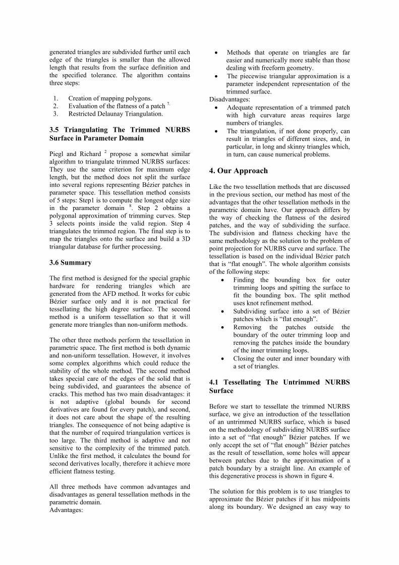
4.1 Tessellating The Untrimmed NURBS Surface Before we start to tessellate the trimmed NURBS surface, we give an introduction of the tessellation of an untrimmed NURBS surface, which is based on the methodology of subdividing NURBS surface into a set of “flat enough” Bézier patches. If we only accept the set of “flat enough” Bézier patches as the result of tessellation, some holes will appear between patches due to the approximation of a patch boundary by a straight line. An example of this degenerative process is shown in figure 4. The solution for this problem is to use triangles to approximate the Bézier patches if it has midpoints along its boundary. We designed an easy way to
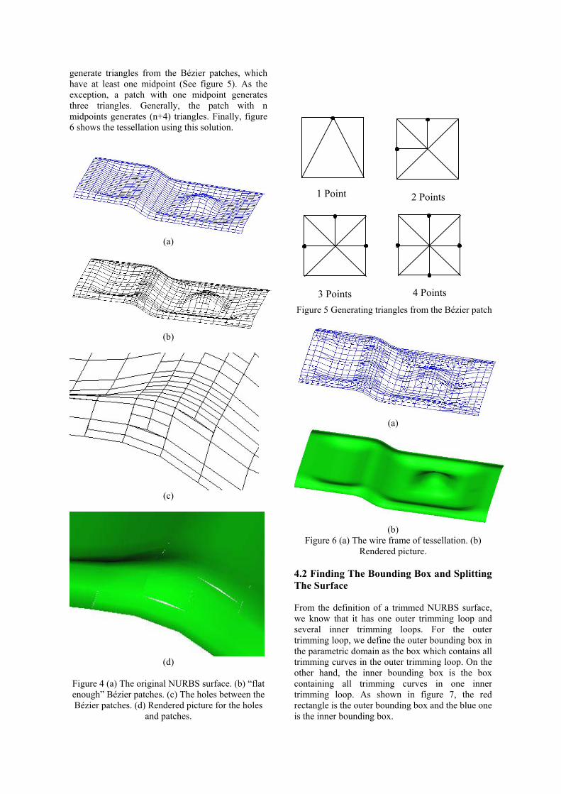
generate triangles from the Bézier patches, which have at least one midpoint (See figure 5). As the exception, a patch with one midpoint generates three triangles. Generally, the patch with n midpoints generates (n+4) triangles. Finally, figure 6 shows the tessellation using this solution.
(a)
(b)
(c)
(d)
Figure 4 (a) The original NURBS surface. (b) “flat enough” Bézier patches. (c) The holes between the Bézier patches. (d) Rendered picture for the holes
and patches.
1 Point 2 Points
4 Points 3 Points Figure 5 Generating triangles from the Bézier patch
(a)
(b)
Figure 6 (a) The wire frame of tessellation. (b) Rendered picture.
4.2 Finding The Bounding Box and Splitting The Surface From the definition of a trimmed NURBS surface, we know that it has one outer trimming loop and several inner trimming loops. For the outer trimming loop, we define the outer bounding box in the parametric domain as the box which contains all trimming curves in the outer trimming loop. On the other hand, the inner bounding box is the box containing all trimming curves in one inner trimming loop. As shown in figure 7, the red rectangle is the outer bounding box and the blue one is the inner bounding box.
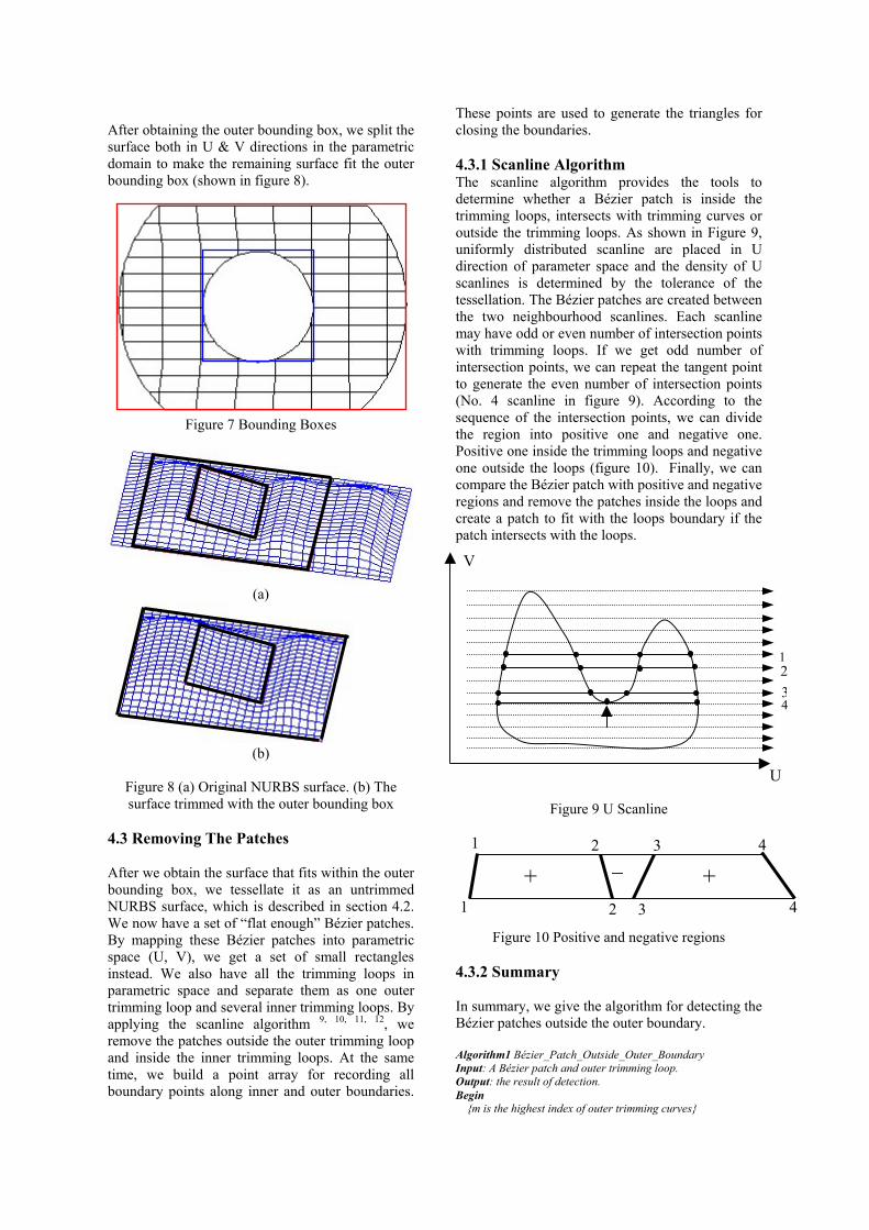
After obtaining the outer bounding box, we split the surface both in U & V directions in the parametric domain to make the remaining surface fit the outer bounding box (shown in figure 8).
Figure 7 Bounding Boxes
(a)
(b)
Figure 8 (a) Original NURBS surface. (b) The surface trimmed with the outer bounding box
4.3 Removing The Patches After we obtain the surface that fits within the outer bounding box, we tessellate it as an untrimmed NURBS surface, which is described in section 4.2. We now have a set of “flat enough” Bézier patches. By mapping these Bézier patches into parametric space (U, V), we get a set of small rectangles instead. We also have all the trimming loops in parametric space and separate them as one outer trimming loop and several inner trimming loops. By applying the scanline algorithm 9, 10, 11, 12, we remove the patches outside the outer trimming loop and inside the inner trimming loops. At the same time, we build a point array for recording all boundary points along inner and outer boundaries.
These points are used to generate the triangles for closing the boundaries. 4.3.1 Scanline Algorithm The scanline algorithm provides the tools to determine whether a Bézier patch is inside the trimming loops, intersects with trimming curves or outside the trimming loops. As shown in Figure 9, uniformly distributed scanline are placed in U direction of parameter space and the density of U scanlines is determined by the tolerance of the tessellation. The Bézier patches are created between the two neighbourhood scanlines. Each scanline may have odd or even number of intersection points with trimming loops. If we get odd number of intersection points, we can repeat the tangent point to generate the even number of intersection points (No. 4 scanline in figure 9). According to the sequence of the intersection points, we can divide the region into positive one and negative one. Positive one inside the trimming loops and negative one outside the loops (figure 10). Finally, we can compare the Bézier patch with positive and negative regions and remove the patches inside the loops and create a patch to fit with the loops boundary if the patch intersects with the loops.
V
Figure 9 U Scanline
Figure 10 Positive and negative regions
4.3.2 Summary In summary, we give the algorithm for detecting the Bézier patches outside the outer boundary. Algorithm1 Bézier_Patch_Outside_Outer_Boundary Input: A Bézier patch and outer trimming loop. Output: the result of detection. Begin {m is the highest index of outer trimming curves}
+ _ + 1 2 3 4
1 2 3 4
1 234
U
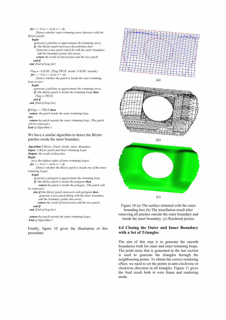
for i = 0 to i < m by i++ do {Detect whether outer trimming curve intersect with the Bézier patch} begin generate a polyline to approximate the trimming curve; if (the Bézier patch intersects the polyline) then Generate a new patch which fit with the outer boundary; Add the boundary points into array; return the result of intersection and the new patch; end if end {End of loop for} Flag ← FALSE; {Flag TRUE: inside; FALSE: outside} for i = 0 to i < m by i++ do {Detect whether the patch is inside the outer trimming loop or not.} begin generate a polyline to approximate the trimming curve; if (the Bézier patch is inside the trimming loop) then Flag ←TRUE; end if end {End of loop for} if Flag == TRUE then return the patch inside the outer trimming loop; else return the patch outside the outer trimming loop; {The patch will be removed;} End of Algorithm 1 We have a similar algorithm to detect the Bézier patches inside the inner boundary. Algorithm 2 Bézier_Patch_Inside_inner_Boundary Input: A Bézier patch and inner trimming loops. Output: the result of detection. Begin {m is the highest index of inner trimming loops} for i = 0 to i < m by i++ do {Detect whether the Bézier patch is inside one of the inner trimming loops} begin generate a polygon to approximate the trimming loop; if (the Bézier patch is inside the polygon) then return the patch is inside the polygon; {The patch will be removed;} else if (the Bézier patch intersects with polygon) then generate a new patch fitting with the inner boundary; add the boundary points into array; return the result of intersection and the new patch; end if end {End of loop for} return the patch outside the inner trimming loops; End of Algorithm 2 Finally, figure 10 gives the illustration of this procedure.
(a)
(b)
(c)
Figure 10 (a) The surface trimmed with the outer
bounding box (b) The tessellation result after removing all patches outside the outer boundary and
inside the inner boundary. (c) Rendered picture
4.4 Closing the Outer and Inner Boundary with a Set of Triangles The aim of this step is to generate the smooth boundaries both for outer and inner trimming loops. The point array that is generated in the last section is used to generate the triangles through the neighbouring points. To obtain the correct rendering effect, we need to set the points in anti-clockwise or clockwise direction in all triangles. Figure 11 gives the final result both in wire frame and rendering mode.
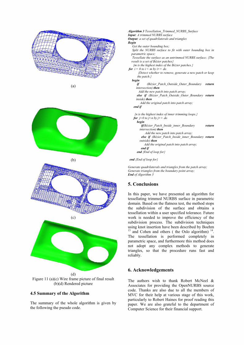
(a)
(b)
(c)
(d)
Figure 11 (a)(c) Wire frame picture of final result (b)(d) Rendered picture
4.5 Summary of the Algorithm The summary of the whole algorithm is given by the following the pseudo code.
Algorithm 3 Tessellation_Trimmed_NURBS_Surface Input: A trimmed NURBS surface Output: a set of quadrilaterals and triangles Begin
Get the outer bounding box; Split the NURBS surface to fit with outer bounding box in parametric space; Tessellate the surface as an untrimmed NURBS surface; {The result is a set of Bézier patches} {m is the highest index of the Bézier patches.}
for i = 0 to i < m by i++ do {Detect whether to remove, generate a new patch or keep the patch.}
begin if (Bézier_Patch_Outside_Outer_Boundary return intersection) then
Add the new patch into patch array; else if (Bézier_Patch_Outside_Outer_Boundary return inside) then
Add the original patch into patch array; end if {n is the highest index of inner trimming loops.} for j=0 to j<n by j++ do begin
if(Bézier_Patch_Inside_inner_Boundary return intersection) then
Add the new patch into patch array; else if (Bézier_Patch_Inside_inner_Boundary return outside) then
Add the original patch into patch array; end if end {End of loop for} end {End of loop for} Generate quadrilaterals and triangles from the patch array; Generate triangles from the boundary point array; End of Algorithm 3 5. Conclusions In this paper, we have presented an algorithm for tessellating trimmed NURBS surface in parametric domain. Based on the flatness test, the method stops the subdivision of the surface and obtains a tessellation within a user specified tolerance. Future work is needed to improve the efficiency of the subdivision process. The subdivision techniques using knot insertion have been described by Boehm 13 and Cohen and others ( the Oslo algorithm) 14. The tessellation is performed completely in parametric space, and furthermore this method does not adopt any complex methods to generate triangles, so that the procedure runs fast and reliably. 6. Acknowledgements The authors wish to thank Robert McNeel & Associates for providing the OpenNURBS source code. Thanks are also due to all the members of MVC for their help at various stage of this work, particularly to Robert Haines for proof reading this paper. We are also grateful to the department of Computer Science for their financial support.
References 1. Alan Watt, 3D Computer Graphics (Third
Edition), Addison-Wesley, pp 128 –129, 2000. 2. Piegl, L.A. and Richard, A.M., Tessellating
trimmed NURBS surface, Computer-Aided Design 27(1), 16-26, 1995.
3. Michael Shantz and Sheue-Ling Chang.,
Rendering trimmed NURBS with adaptive forward differencing, Computer Graphics Proceedings of Siggraph’88, 1988.
4. Salim S. Abi-Ezzi and Leon A. Shirman. ,
Tessellation of curved surfaces under highly varying transformation, Proceedings of EUROGRAPHICS ’93, pp385-397, 1991.
5. Salim S. Abi-Ezzi and Srikanth Subramaniam,
Fast tessellation of trimmed NURBS surface, Proceedings of EUROGRAPHICS ’94, 1994.
6. Sheng, X and Hirsh, B.E. , Triangulation of
trimmed surfaces in parametric space, Computer-Aided Design 24(8), 437-444, 1992.
7. Filip, D, Magedson, R and Markot, R, Surface
algorithm using bounds on derivatives, Computer-Aided Geometric Design Vol. 3, 295-311, 1986.
8. Vigo, M., Directional adaptive surface
triangulation, Computer-Aided Design 16, 107-126, 1999.
9. Jonathan E. Steinhart and James Arvo,
Graphics Gems II, ISBN 0-12-064480-0, Academic Press, Inc, 1991.
10. Samet, Hanan, Applications of Spatial Data
Structures, ISBN 0-201-50300-X, Addison-Wesley, Reading, MA. (I.9 Scanline Coherent Shape Algebra; IV.7 Quadtree /Octree-to-Boundary Conversion), 1990.
11. Samet, Hanan, The Design and Analysis of
Spatial Data Structures. ISBN 0-201-50255-0, Addison-Wesley, Reading, MA (I.9 Scanline Coherent Shape Algebra), 1990.
12. Atkinson, William D., Method and Apparatus
for Image Compression and Manipulation, United States Patent Number 4,622,545. (I.9 Scanline Coherent Shape Algebra), 1986.
13. Wolfgang Boehm, Inserting New Knots into
B-Spline Curves, Computer Aided Design 12, 199-201, 1980.
14. Elaine Cohen, Tom Lyche, and Richard
Riesenfeld, Discrete B-Splines and Subdivision Techniques in Computer-Aided Geometric Design and Computer Graphics, Computer Graphics and Image Processing 14, 1980.