Outline Notes: Diffusive flux Notes: Advection-diffusion Notes:
Prof. David R. JacksonDept. of ECE
Notes 4
ECE 5317-6351 Microwave Engineering
Fall 2019
Transmission LinesPart 3: Baluns
1
Adapted from notes by Prof. Jeffery T. Williams
Baluns
2
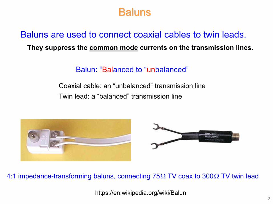
Baluns are used to connect coaxial cables to twin leads.
4:1 impedance-transforming baluns, connecting 75Ω TV coax to 300Ω TV twin lead
Coaxial cable: an “unbalanced” transmission lineTwin lead: a “balanced” transmission line
Balun: “Balanced to “unbalanced”
https://en.wikipedia.org/wiki/Balun
They suppress the common mode currents on the transmission lines.
Baluns (cont.)
3
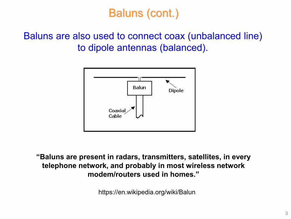
https://en.wikipedia.org/wiki/Balun
“Baluns are present in radars, transmitters, satellites, in every telephone network, and probably in most wireless network
modem/routers used in homes.”
Baluns are also used to connect coax (unbalanced line) to dipole antennas (balanced).
4
Ground (zero volts)
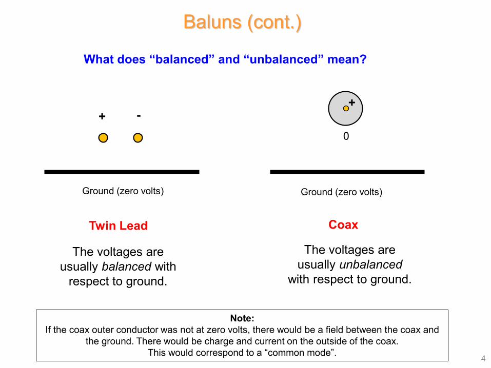
+ -
Ground (zero volts)
+
0
The voltages are usually unbalanced
with respect to ground.
The voltages are usually balanced with
respect to ground.
CoaxTwin Lead
Baluns (cont.)
What does “balanced” and “unbalanced” mean?
Note:If the coax outer conductor was not at zero volts, there would be a field between the coax and
the ground. There would be charge and current on the outside of the coax. This would correspond to a “common mode”.
Baluns (cont.)
5
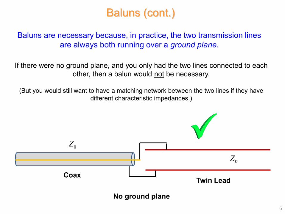
Baluns are necessary because, in practice, the two transmission lines are always both running over a ground plane.
If there were no ground plane, and you only had the two lines connected to each other, then a balun would not be necessary.
(But you would still want to have a matching network between the two lines if they have different characteristic impedances.)
CoaxTwin Lead
No ground plane
0Z
0Z
Baluns (cont.)
6
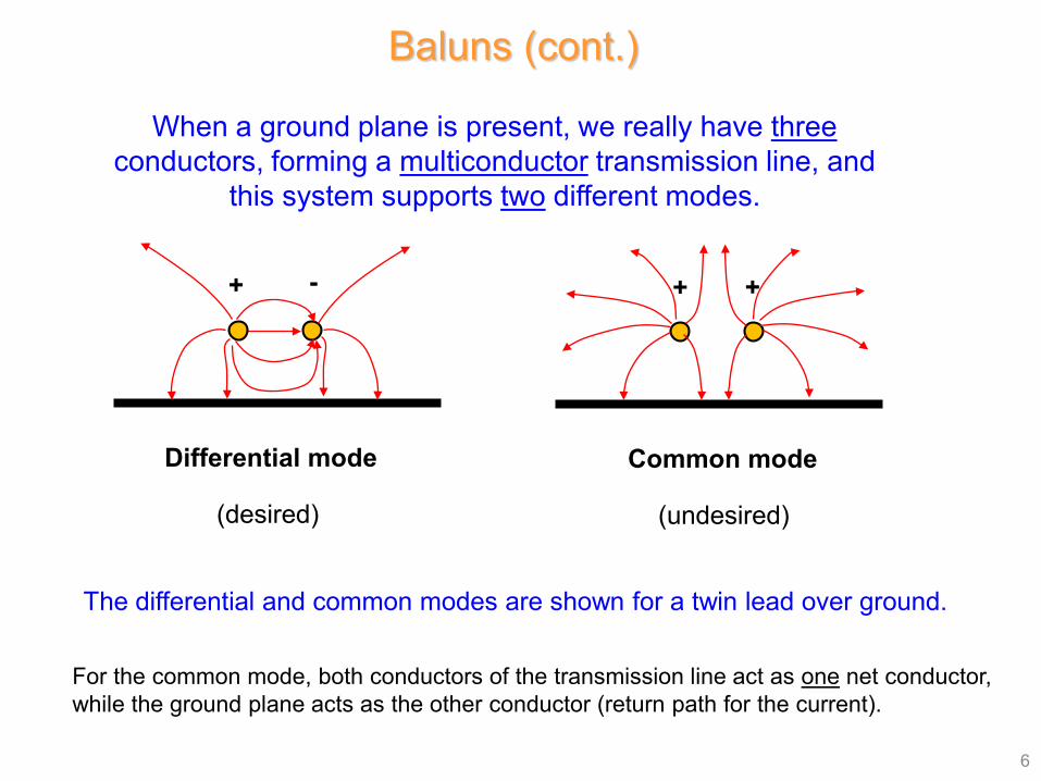
When a ground plane is present, we really have threeconductors, forming a multiconductor transmission line, and
this system supports two different modes.
The differential and common modes are shown for a twin lead over ground.
For the common mode, both conductors of the transmission line act as one net conductor, while the ground plane acts as the other conductor (return path for the current).
Differential mode
(desired)
+ - + +
Common mode
(undesired)
Baluns (cont.)
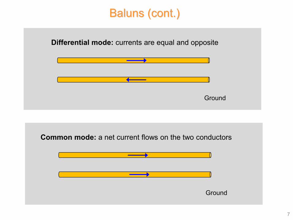
7
Ground
Differential mode: currents are equal and opposite
Ground
Common mode: a net current flows on the two conductors
Baluns (cont.)
8
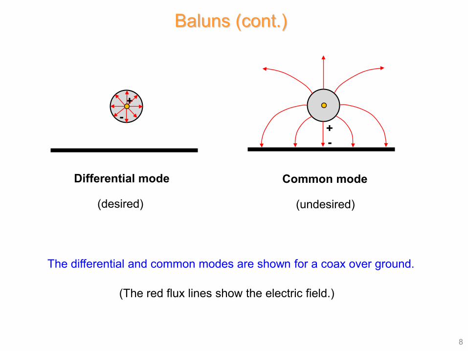
Differential mode
(desired)
Common mode
(undesired)
The differential and common modes are shown for a coax over ground.
+-
+-
(The red flux lines show the electric field.)
Baluns for Coax to Twin Lead
9
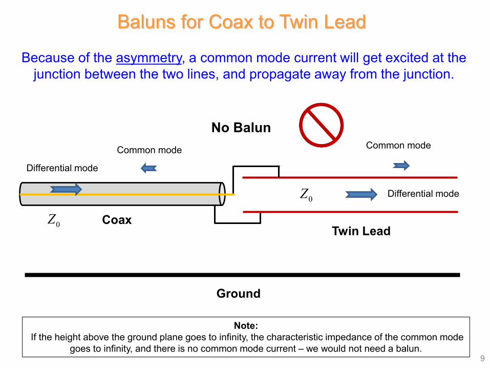
Because of the asymmetry, a common mode current will get excited at the junction between the two lines, and propagate away from the junction.
Ground
Note:If the height above the ground plane goes to infinity, the characteristic impedance of the common mode
goes to infinity, and there is no common mode current – we would not need a balun.
CoaxTwin Lead
Common modeCommon mode
No Balun
Differential mode
Differential mode
0Z0Z
10
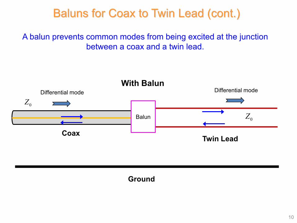
A balun prevents common modes from being excited at the junction between a coax and a twin lead.
Ground
Baluns for Coax to Twin Lead (cont.)
With Balun
CoaxTwin Lead
Differential mode Differential mode
Balun 0Z0Z
11
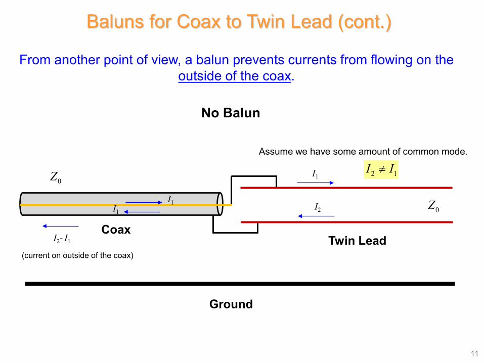
From another point of view, a balun prevents currents from flowing on the outside of the coax.
Baluns for Coax to Twin Lead (cont.)
No Balun
CoaxTwin Lead
Ground
I1
I1
I2I1
I2- I1
(current on outside of the coax)
2 1I I≠
0Z
0Z
Assume we have some amount of common mode.
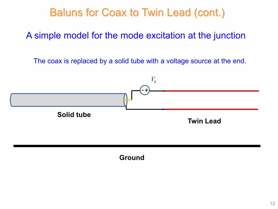
12
A simple model for the mode excitation at the junction
The coax is replaced by a solid tube with a voltage source at the end.
Solid tubeTwin Lead
Ground
+-0V
Baluns for Coax to Twin Lead (cont.)
13
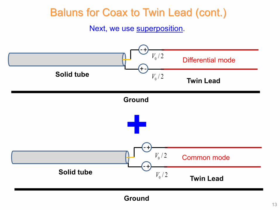
Next, we use superposition.
+Solid tube
Twin Lead
Ground
+-
+-Differential mode0 / 2V
0 / 2V
Solid tubeTwin Lead
Ground
+-
+-Common mode0 / 2V
0 / 2V
Baluns for Coax to Twin Lead (cont.)
14
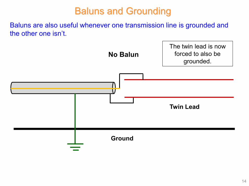
Baluns are also useful whenever one transmission line is grounded and the other one isn’t.
Baluns and Grounding
No Balun
Twin Lead
Ground
The twin lead is now forced to also be
grounded.
15
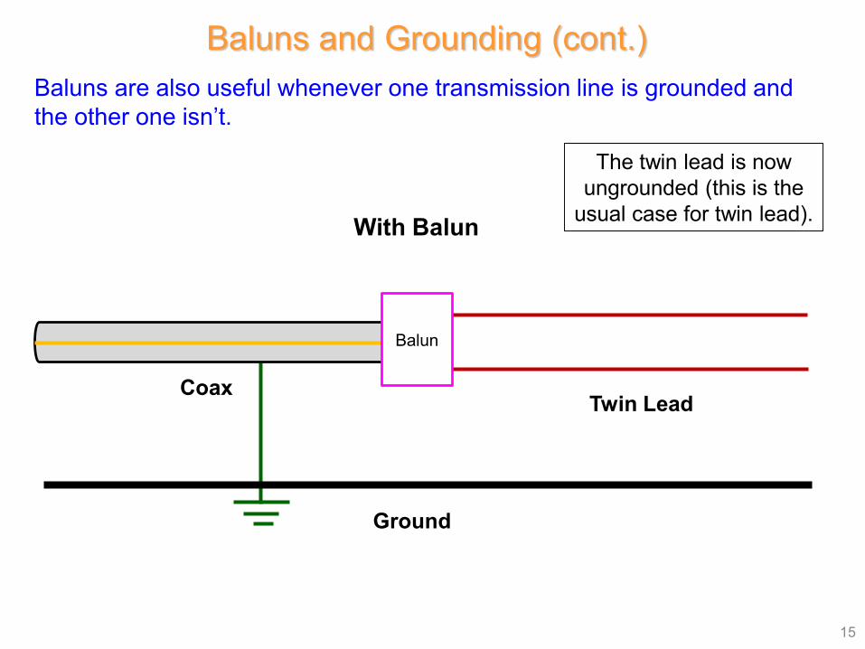
Baluns are also useful whenever one transmission line is grounded and the other one isn’t.
Baluns and Grounding (cont.)
The twin lead is now ungrounded (this is the
usual case for twin lead).With Balun
CoaxTwin Lead
Ground
Balun
Baluns using Transformers
16
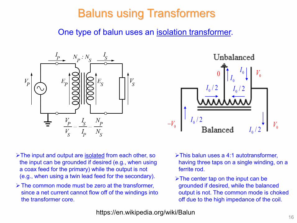
One type of balun uses an isolation transformer.
https://en.wikipedia.org/wiki/Balun
The input and output are isolated from each other, so the input can be grounded if desired (e.g., when using a coax feed for the primary) while the output is not (e.g., when using a twin lead feed for the secondary). The common mode must be zero at the transformer,
since a net current cannot flow off of the windings into the transformer core.
This balun uses a 4:1 autotransformer, having three taps on a single winding, on a ferrite rod.The center tap on the input can be
grounded if desired, while the balanced output is not. The common mode is choked off due to the high impedance of the coil.
0V0
0V0V−
0I0I
0 / 2I
0 / 2I0 / 2I
0 / 2I
17
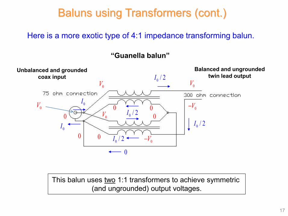
Here is a more exotic type of 4:1 impedance transforming balun.
This balun uses two 1:1 transformers to achieve symmetric (and ungrounded) output voltages.
“Guanella balun”
0V
0V−
0V
0V0V
0V−
0 / 2I
0 / 2I
0I
0I00
00
0
0
0 / 2I
0 / 2I
0
Baluns using Transformers (cont.)
Balanced and ungrounded twin lead output
Unbalanced and grounded coax input
18
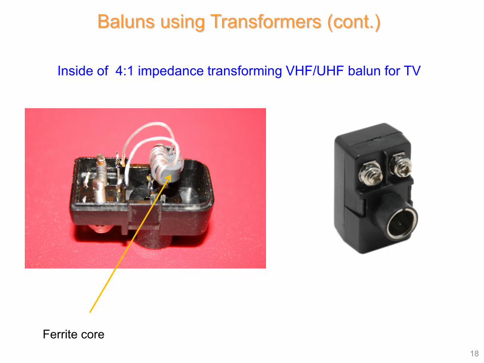
Inside of 4:1 impedance transforming VHF/UHF balun for TV
Ferrite core
Baluns using Transformers (cont.)
19
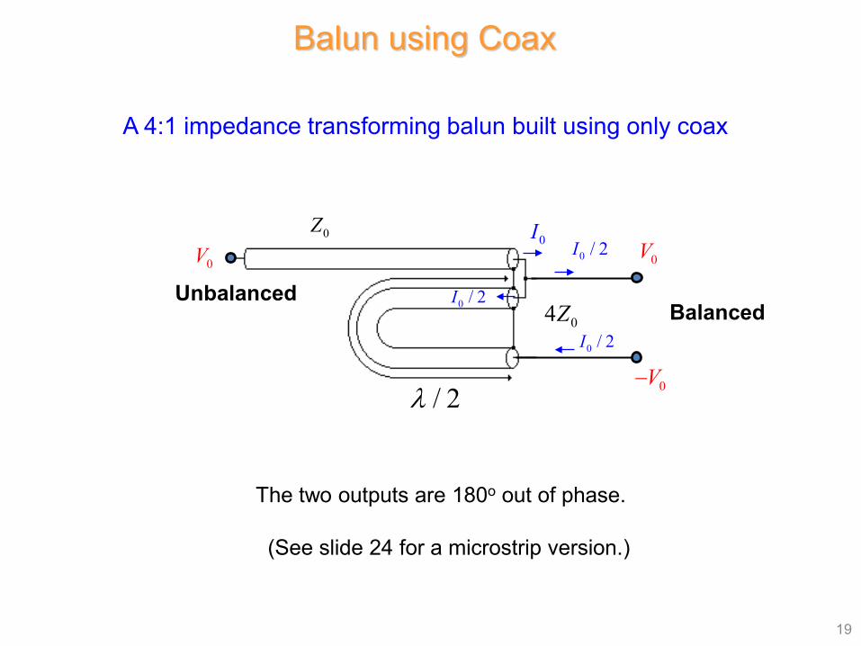
A 4:1 impedance transforming balun built using only coax
Balun using Coax
The two outputs are 180o out of phase.
(See slide 24 for a microstrip version.)
Unbalanced
/ 2λ
0Z
04Z Balanced
0V
0V−
0V0I
0 / 2I
0 / 2I
0 / 2I
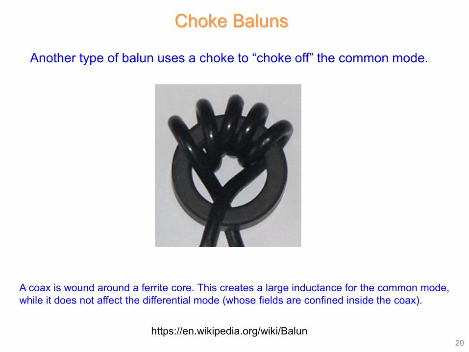
Choke Baluns
20
Another type of balun uses a choke to “choke off” the common mode.
https://en.wikipedia.org/wiki/Balun
A coax is wound around a ferrite core. This creates a large inductance for the common mode, while it does not affect the differential mode (whose fields are confined inside the coax).
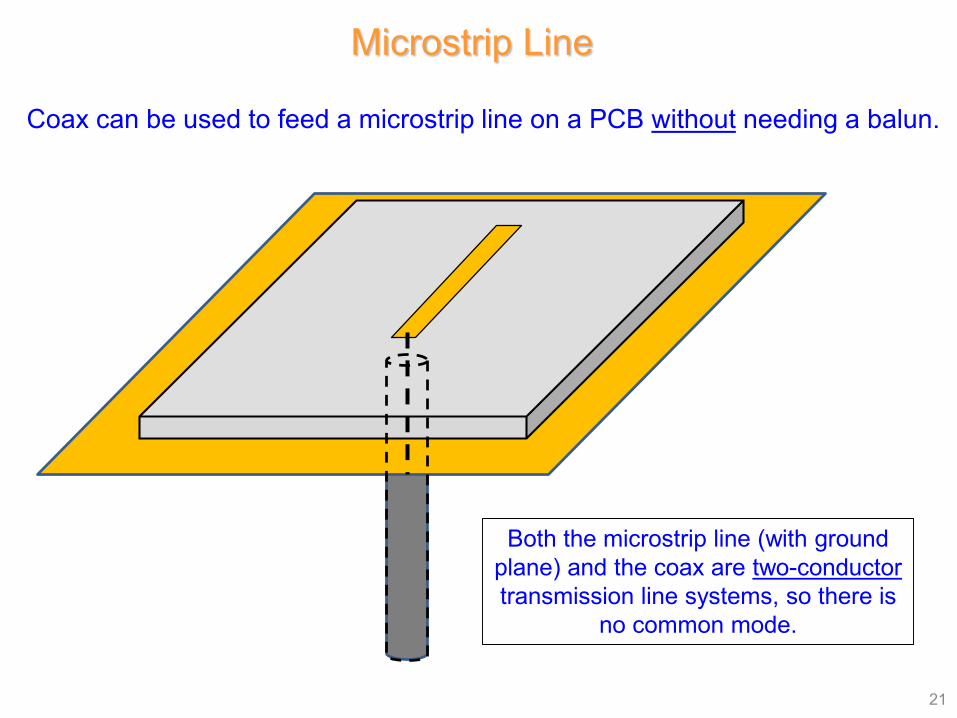
Microstrip Line
21
Coax can be used to feed a microstrip line on a PCB without needing a balun.
Both the microstrip line (with ground plane) and the coax are two-conductortransmission line systems, so there is
no common mode.
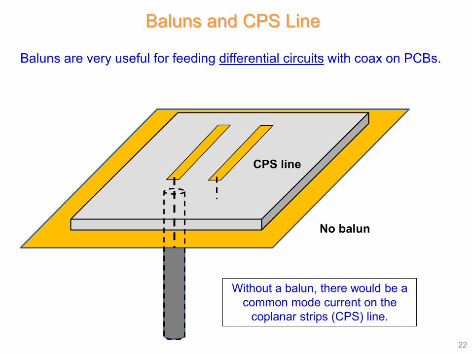
Baluns and CPS Line
22
Baluns are very useful for feeding differential circuits with coax on PCBs.
No balun
Without a balun, there would be a common mode current on the
coplanar strips (CPS) line.
CPS line
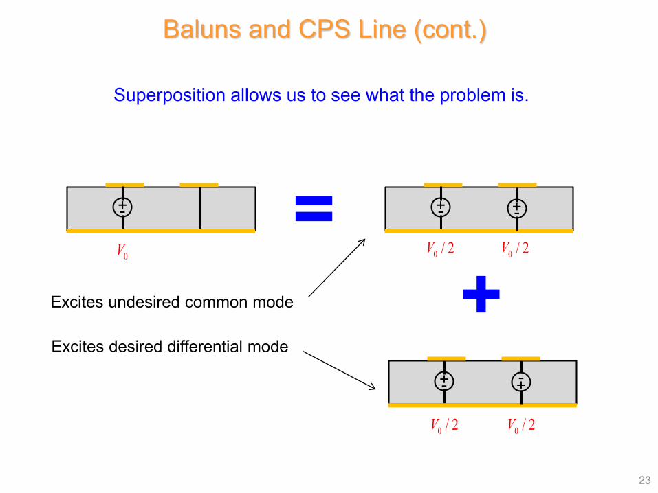
23
=+
Excites desired differential mode
Excites undesired common mode
Superposition allows us to see what the problem is.
+-
0V
+- +-
0 / 2V 0 / 2V
+- -+
0 / 2V 0 / 2V
Baluns and CPS Line (cont.)
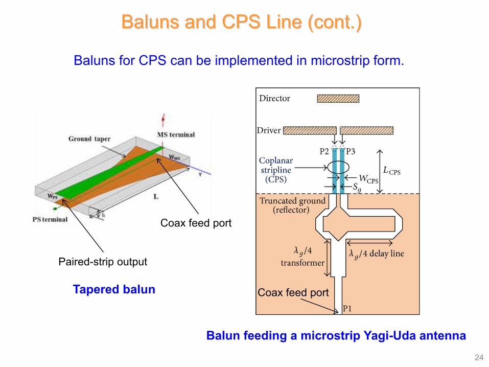
24
Baluns for CPS can be implemented in microstrip form.
Balun feeding a microstrip Yagi-Uda antenna
Tapered balun
Coax feed port
Paired-strip output
Baluns and CPS Line (cont.)
Coax feed port
25
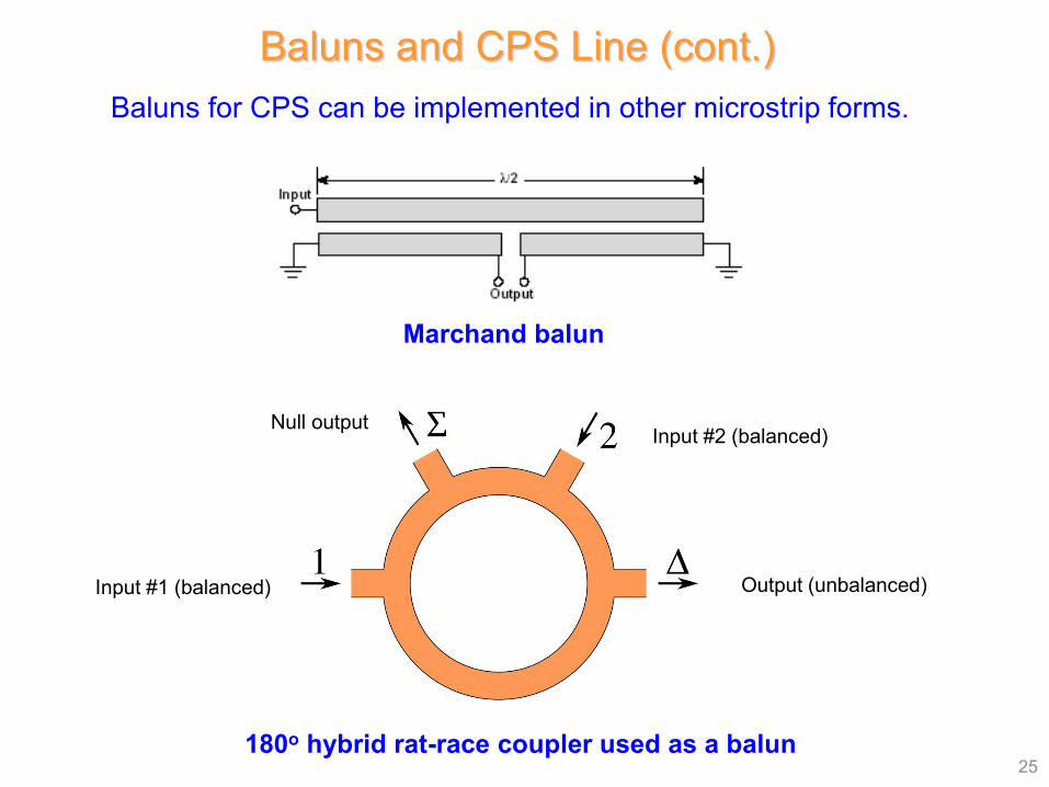
Baluns for CPS can be implemented in other microstrip forms.
Marchand balun
180o hybrid rat-race coupler used as a balun
Output (unbalanced)
Input #2 (balanced)
Input #1 (balanced)
Null output
Baluns and CPS Line (cont.)
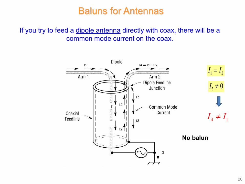
26
If you try to feed a dipole antenna directly with coax, there will be a common mode current on the coax.
No balun
1 2I I=
3 0I ≠
Baluns for Antennas
4 1I I≠
27
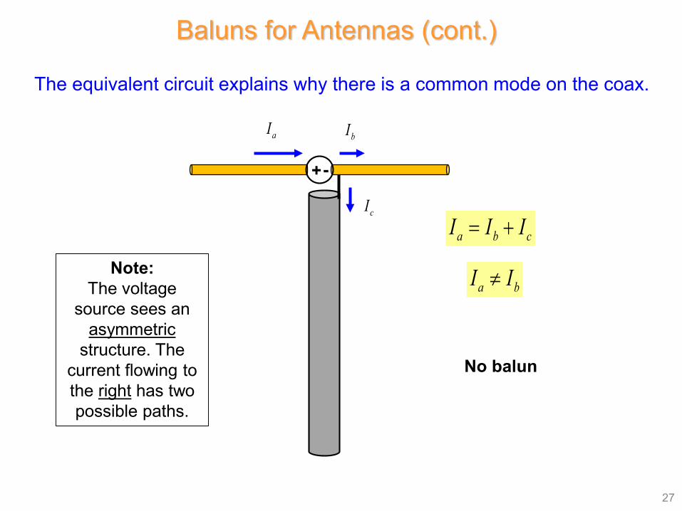
The equivalent circuit explains why there is a common mode on the coax.
No balun
Note:The voltage
source sees an asymmetric
structure. The current flowing to the right has two possible paths.
+-
aI bI
cI
a b cI I I= +
a bI I≠
Baluns for Antennas (cont.)
28
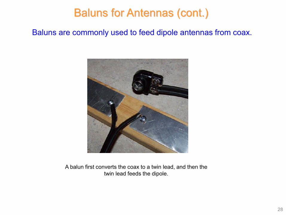
Baluns are commonly used to feed dipole antennas from coax.
A balun first converts the coax to a twin lead, and then the twin lead feeds the dipole.
Baluns for Antennas (cont.)
29
/ 4λ
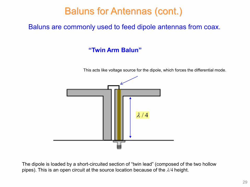
This acts like voltage source for the dipole, which forces the differential mode.
The dipole is loaded by a short-circuited section of “twin lead” (composed of the two hollow pipes). This is an open circuit at the source location because of the λ/4 height.
Baluns are commonly used to feed dipole antennas from coax.
Baluns for Antennas (cont.)
“Twin Arm Balun”
30
0 / 4λ
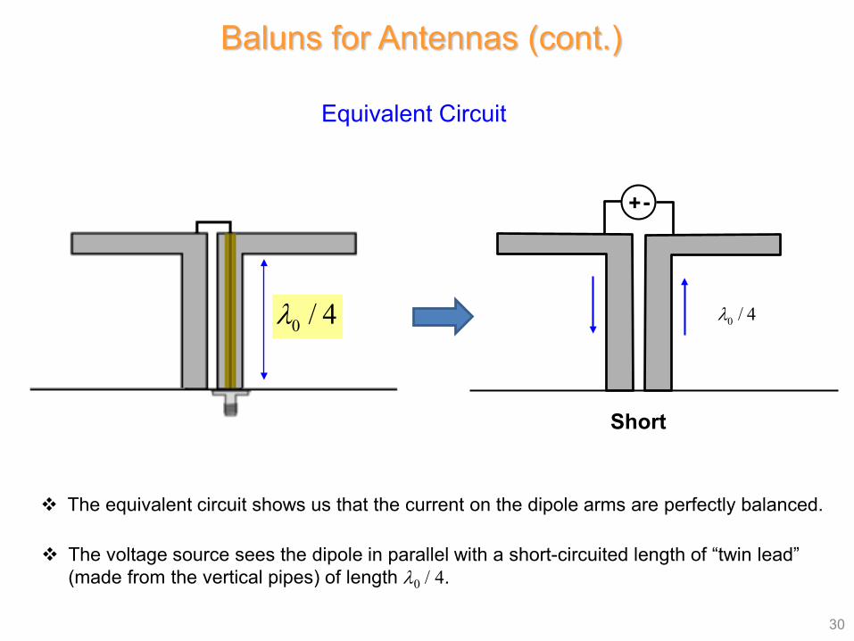
Equivalent Circuit
Baluns for Antennas (cont.)
The equivalent circuit shows us that the current on the dipole arms are perfectly balanced.
+-
Short
0 / 4λ
The voltage source sees the dipole in parallel with a short-circuited length of “twin lead” (made from the vertical pipes) of length λ0 / 4.
31
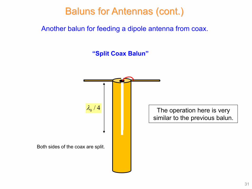
Another balun for feeding a dipole antenna from coax.
“Split Coax Balun”
0 / 4λ
Baluns for Antennas (cont.)
The operation here is very similar to the previous balun.
Both sides of the coax are split.
32
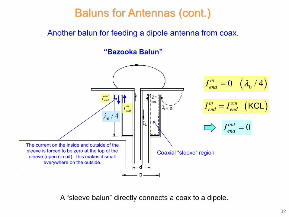
A “sleeve balun” directly connects a coax to a dipole.
“Bazooka Balun”
Baluns for Antennas (cont.)
( )00 / 4inendI λ=
( )in outend endI I= KCL
0outendI =
Another balun for feeding a dipole antenna from coax.
Coaxial “sleeve” regionThe current on the inside and outside of the sleeve is forced to be zero at the top of the sleeve (open circuit). This makes it small
everywhere on the outside.
inendI
outendI
0 / 4λ
33
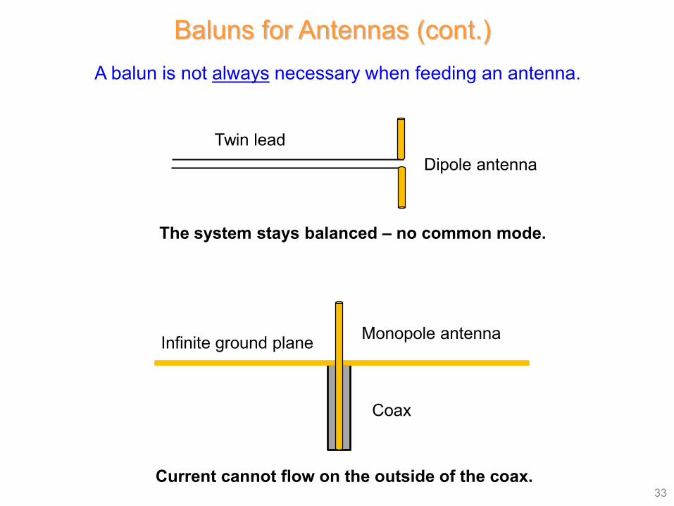
A balun is not always necessary when feeding an antenna.
Dipole antennaTwin lead
Monopole antenna
Coax
Infinite ground plane
The system stays balanced – no common mode.
Current cannot flow on the outside of the coax.
Baluns for Antennas (cont.)
Baluns and Measuring Probes
34
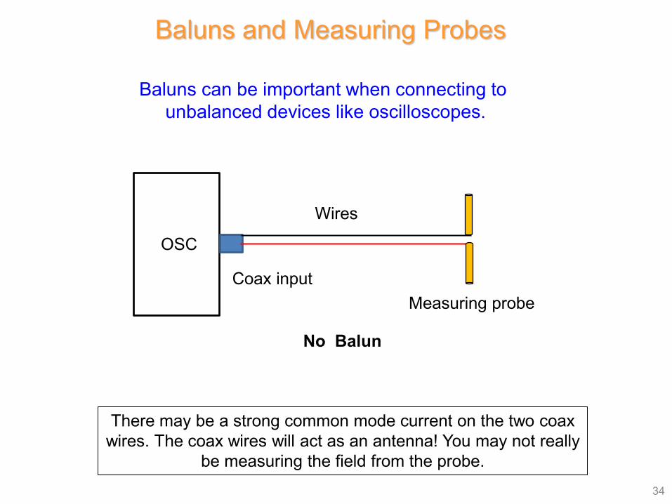
Baluns can be important when connecting to unbalanced devices like oscilloscopes.
OSC
Coax inputMeasuring probe
Wires
No Balun
There may be a strong common mode current on the two coax wires. The coax wires will act as an antenna! You may not really
be measuring the field from the probe.
35
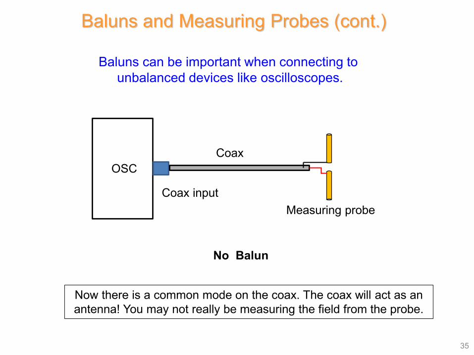
Baluns can be important when connecting to unbalanced devices like oscilloscopes.
No Balun
Now there is a common mode on the coax. The coax will act as an antenna! You may not really be measuring the field from the probe.
Baluns and Measuring Probes (cont.)
OSC
Coax inputMeasuring probe
Coax
36
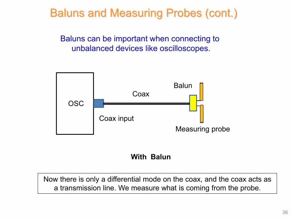
Baluns can be important when connecting to unbalanced devices like oscilloscopes.
With Balun
Now there is only a differential mode on the coax, and the coax acts as a transmission line. We measure what is coming from the probe.
Baluns and Measuring Probes (cont.)
OSC
Coax inputMeasuring probe
CoaxBalun