Active static and seismic earth pressure for c–φ soils · The results based on the proposed...
14
Active static and seismic earth pressure for c–φ soils Magued Iskander n , Zhibo (Chris) Chen , Mehdi Omidvar, Ivan Guzman, Omar Elsherif Polytechnic Institute of New York University, USA Received 1 October 2012; received in revised form 23 April 2013; accepted 15 June 2013 Available online 26 September 2013 Abstract Rankine classic earth pressure solution has been expanded to predict the seismic active earth pressure behind rigid walls supporting c–φ backfill considering both wall inclination and backfill slope. The proposed formulation is based on Rankine's conjugate stress concept, without employing any additional assumptions. The developed expressions can be used for the static and pseudo-static seismic analyses of c–φ backfill. The results based on the proposed formulations are found to be identical to those computed with the Mononobe–Okabe method for cohesionless soils, provided the same wall friction angle is employed. For c–φ soils, the formulation yields comparable results to available solutions for cases where a comparison is feasible. Design charts are presented for calculating the net active horizontal thrust behind a rigid wall for a variety of horizontal pseudo-static accelerations, values of cohesion, soil internal friction angles, wall inclinations, and backfill slope combinations. The effects of the vertical pseudo-static acceleration on the active earth pressure and the depth of tension cracks have also been explored. In addition, examples are provided to illustrate the application of the proposed method. & 2013 The Japanese Geotechnical Society. Production and hosting by Elsevier B.V. All rights reserved. Keywords: Mononabe–Okabe method; Rankine; Retaining wall; Seismic; Limit state analysis 1. Introduction The estimation of seismic active earth pressure on retaining walls from backfill soils is an important problem in earthquake engineering. Pioneering works on seismic earth pressure on a rigid retaining wall have been reported by Okabe (1924) and Mononobe and Matsuo (1929, 1932). Their analyses have provided a popular solution to the problem of cohesionless soils. The Mononobe–Okabe (M–O) method is a pseudo-static approach, which incorporates seismic accelerations in the form of inertial forces into Coulomb's 1776 limit equilibrium analysis (Heyman, 1997). While the original M–O solution did not account for cohesion, several authors have extended the M–O solution to account for c–φ soils. For example, Saran and Prakash (1968) and Saran and Gupta (2003) proposed a solution for seismic earth pressure on a retaining wall supporting c–φ soils, in which the contributions of soil weight and cohesion are optimized separately, in some cases leading to two distinct failure planes. Shukla et al. (2009) developed an expression for the total seismic active force on a retaining wall supporting c–φ backfill based on the Coulomb sliding wedge concept, disregarding the soil–wall friction component. In all Coulomb type of solutions, only force equilibrium is used; and therefore, the distribution of the lateral thrust is not deter- mined. On the other hand, Rankine's (1857) active earth pressure is a stress field-based solution, which does not require specifying failure kinematics (Huntington, 1957). The original Rankine solution considered static lateral earth pressure against The Japanese Geotechnical Society www.sciencedirect.com journal homepage: www.elsevier.com/locate/sandf Soils and Foundations 0038-0806 & 2013 The Japanese Geotechnical Society. Production and hosting by Elsevier B.V. All rights reserved. http://dx.doi.org/10.1016/j.sandf.2013.08.003 n Corresponding author. E-mail address: [email protected] (M. Iskander). Peer review under responsibility of The Japanese Geotechnical Society. Soils and Foundations 2013;53(5):639–652
Transcript of Active static and seismic earth pressure for c–φ soils · The results based on the proposed...
The Japanese Geotechnical Society
Soils and Foundations
Soils and Foundations 2013;53(5):639–652
0038-0http://d
nCorE-mPeer
806 & 201x.doi.org/
respondinail addrereview un
www.sciencedirect.comjournal homepage: www.elsevier.com/locate/sandf
Active static and seismic earth pressure for c–φ soils
Magued Iskandern, Zhibo (Chris) Chen , Mehdi Omidvar, Ivan Guzman, Omar Elsherif
Polytechnic Institute of New York University, USA
Received 1 October 2012; received in revised form 23 April 2013; accepted 15 June 2013Available online 26 September 2013
Abstract
Rankine classic earth pressure solution has been expanded to predict the seismic active earth pressure behind rigid walls supporting c–φbackfill considering both wall inclination and backfill slope. The proposed formulation is based on Rankine's conjugate stress concept, withoutemploying any additional assumptions. The developed expressions can be used for the static and pseudo-static seismic analyses of c–φ backfill.The results based on the proposed formulations are found to be identical to those computed with the Mononobe–Okabe method for cohesionlesssoils, provided the same wall friction angle is employed. For c–φ soils, the formulation yields comparable results to available solutions for caseswhere a comparison is feasible. Design charts are presented for calculating the net active horizontal thrust behind a rigid wall for a variety ofhorizontal pseudo-static accelerations, values of cohesion, soil internal friction angles, wall inclinations, and backfill slope combinations. Theeffects of the vertical pseudo-static acceleration on the active earth pressure and the depth of tension cracks have also been explored. In addition,examples are provided to illustrate the application of the proposed method.& 2013 The Japanese Geotechnical Society. Production and hosting by Elsevier B.V. All rights reserved.
Keywords: Mononabe–Okabe method; Rankine; Retaining wall; Seismic; Limit state analysis
1. Introduction
The estimation of seismic active earth pressure on retainingwalls from backfill soils is an important problem in earthquakeengineering. Pioneering works on seismic earth pressure on arigid retaining wall have been reported by Okabe (1924) andMononobe and Matsuo (1929, 1932). Their analyses haveprovided a popular solution to the problem of cohesionlesssoils. The Mononobe–Okabe (M–O) method is a pseudo-staticapproach, which incorporates seismic accelerations in the form
3 The Japanese Geotechnical Society. Production and hosting by10.1016/j.sandf.2013.08.003
g author.ss: [email protected] (M. Iskander).der responsibility of The Japanese Geotechnical Society.
of inertial forces into Coulomb's 1776 limit equilibriumanalysis (Heyman, 1997). While the original M–O solutiondid not account for cohesion, several authors have extendedthe M–O solution to account for c–φ soils. For example, Saranand Prakash (1968) and Saran and Gupta (2003) proposed asolution for seismic earth pressure on a retaining wallsupporting c–φ soils, in which the contributions of soil weightand cohesion are optimized separately, in some cases leadingto two distinct failure planes. Shukla et al. (2009) developed anexpression for the total seismic active force on a retaining wallsupporting c–φ backfill based on the Coulomb sliding wedgeconcept, disregarding the soil–wall friction component. In allCoulomb type of solutions, only force equilibrium is used; andtherefore, the distribution of the lateral thrust is not deter-mined. On the other hand, Rankine's (1857) active earthpressure is a stress field-based solution, which does not requirespecifying failure kinematics (Huntington, 1957). The originalRankine solution considered static lateral earth pressure against
Elsevier B.V. All rights reserved.
M. Iskander et al. / Soils and Foundations 53 (2013) 639–652640
a vertical rigid wall supporting cohesionless backfill with aground surface unlimited in lateral extent and depth. Chu(1991) extended Rankine's method to account for wallinclination, and Mazindrani and Ganjali (1997) presented asimilar solution for cohesive backfill under static conditions.Limitations of stress-based solutions, as well as a discussion onthe general limitations of Coulomb-type solutions can be foundin Mylonakis et al. (2007).
In addition to Coulomb and Rankine's earth pressure theory,other theoretical solutions have been developed to computelateral earth pressure. Caquot and Kerisel (1948) developedtables of earth pressure coefficients based on the logarithmicspiral failure surface. Sokolovskii (1965) developed a char-acteristic method to compute lateral earth pressure based on afinite-difference solution. Habibagahi and Ghahramani (1979)developed a solution for lateral earth pressure coefficientsbased on the zero extension line theory. Notwithstanding thesignificance of these contributions, none of the aforementionedmethods can be used for c–φ backfill under seismic conditions.Richards and Shi (1994) presented a plasticity-based solutionto calculate seismic lateral earth pressure limited to verticalwalls retaining horizontal c–φ backfill. Due to the complexityof the soil–wall interaction, numerical techniques have recentlybeen adopted to compute the seismic earth pressure against aretaining wall (Al-Homoud and Whitman, 1994; Gazetas et al.,2004; Psarropoulos et al., 2005; Madabhushi and Zeng, 2007;Tiznado and Rodriguez-Roa, 2011). However, numericalmodeling is generally costly, time consuming and difficult toimplement.
In practice, when computing earth pressure against retainingwalls, it is often assumed that the backfill is cohesionless.However, most natural deposits have some fines content thatexhibits some degree of cohesion (Sitar et al., 2012). Andersonet al. (2008) found that the contribution of cohesion to areduction in seismic earth pressure on retaining walls could be
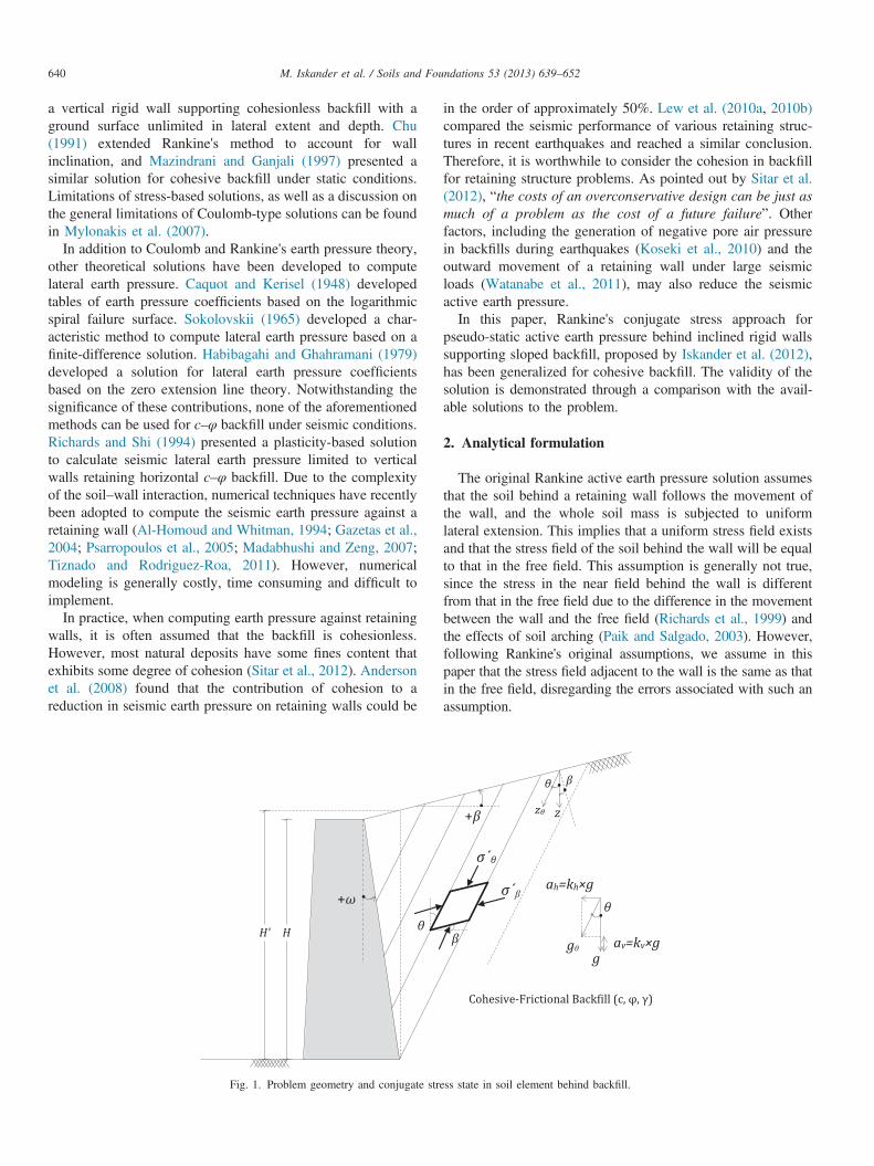
Fig. 1. Problem geometry and conjugate str
in the order of approximately 50%. Lew et al. (2010a, 2010b)compared the seismic performance of various retaining struc-tures in recent earthquakes and reached a similar conclusion.Therefore, it is worthwhile to consider the cohesion in backfillfor retaining structure problems. As pointed out by Sitar et al.(2012), “the costs of an overconservative design can be just asmuch of a problem as the cost of a future failure”. Otherfactors, including the generation of negative pore air pressurein backfills during earthquakes (Koseki et al., 2010) and theoutward movement of a retaining wall under large seismicloads (Watanabe et al., 2011), may also reduce the seismicactive earth pressure.In this paper, Rankine's conjugate stress approach for
pseudo-static active earth pressure behind inclined rigid wallssupporting sloped backfill, proposed by Iskander et al. (2012),has been generalized for cohesive backfill. The validity of thesolution is demonstrated through a comparison with the avail-able solutions to the problem.
2. Analytical formulation
The original Rankine active earth pressure solution assumesthat the soil behind a retaining wall follows the movement ofthe wall, and the whole soil mass is subjected to uniformlateral extension. This implies that a uniform stress field existsand that the stress field of the soil behind the wall will be equalto that in the free field. This assumption is generally not true,since the stress in the near field behind the wall is differentfrom that in the free field due to the difference in the movementbetween the wall and the free field (Richards et al., 1999) andthe effects of soil arching (Paik and Salgado, 2003). However,following Rankine's original assumptions, we assume in thispaper that the stress field adjacent to the wall is the same as thatin the free field, disregarding the errors associated with such anassumption.
ess state in soil element behind backfill.
M. Iskander et al. / Soils and Foundations 53 (2013) 639–652 641
The pseudo-static method is adopted in our formulation toanalyze the seismic response of backfill on the retaining wall,which ignores the time effect of the applied earthquake load.As a result, it cannot represent the actual complex seismicbehavior of the soil during an earthquake (Nakamura, 2006;Ghosh and Sharma, 2010). Nevertheless, it is still one ofthe most popular approaches used in earthquake engineering.In the pseudo-static approach, seismic forces are represented asinertial body forces acting on the wall, in addition to otherstatic forces. These seismic forces are computed using uniformpseudo-static horizontal and vertical accelerations, ah=khg andav=kvg, where kh and kv are the horizontal and vertical seismiccoefficients, respectively.
Consider the problem shown in Fig. 1, namely, a rigid,inclined wall with an inclination of ω retaining a c–φ backfillof surface slope β and unit weight γ, internal friction angle φand cohesion c. The combined action of gravitational accel-eration, g, and the horizontal and vertical pseudo-staticaccelerations, ah and av, can be represented by a singleacceleration field acting at an angle θ to the vertical, asdenoted in Fig. 1 (Lancellotta, 2007). Therefore, the effect ofthe inertial forces can be incorporated into the static problemby modifying the acceleration field to a modified value of gθ,oriented at an angle θ to the vertical. It then follows that γ isalso modified to γθ. Modified acceleration field gθ has amodified unit weight γθ and is inclined to the vertical axis
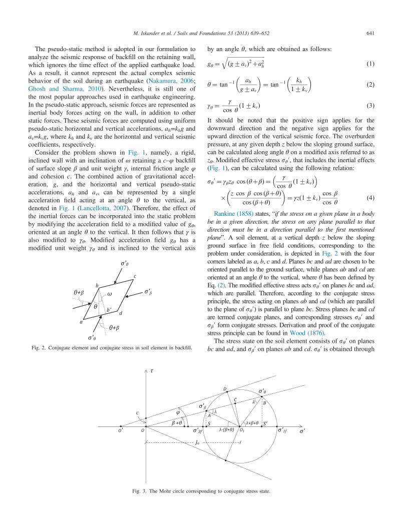
Fig. 2. Conjugate element and conjugate stress in soil element in backfill.
Fig. 3. The Mohr circle correspon
by an angle θ, which are obtained as follows:
gθ ¼ffiffiffiffiffiffiffiffiffiffiffiffiffiffiffiffiffiffiffiffiffiffiffiffiffiffiffiðg7avÞ2þa2h
qð1Þ
θ¼ tan �1 ahg7av
� �¼ tan �1 kh
17kv
� �ð2Þ
γθ ¼γ
cos θð17kvÞ ð3Þ
It should be noted that the positive sign applies for thedownward direction and the negative sign applies for theupward direction of the vertical seismic force. The overburdenpressure, at any given depth z below the sloping ground surface,can be calculated along angle θ on a modified axis referred to aszθ. Modified effective stress sθ 0, that includes the inertial effects(Fig. 1), can be calculated using the following relation:
sθ 0 ¼ γθzθ cos ðθþβÞ ¼ γ
cos θð17kvÞ
� �� z cos β cos ðβþθÞ
cos ðβþθÞ
� �¼ γzð17kvÞ
cos β
cos θð4Þ
Rankine (1858) states, “if the stress on a given plane in a bodybe in a given direction, the stress on any plane parallel to thatdirection must be in a direction parallel to the first mentionedplane”. A soil element, at a vertical depth z below the slopingground surface in free field conditions, corresponding to theproblem under consideration, is depicted in Fig. 2 with the fourcorners labeled as a, b, c and d. Planes bc and ad are chosen to beoriented parallel to the ground surface, while planes ab and cd areoriented at an angle θ to the vertical, where θ has been defined byEq. (2). The modified effective stress acts sθ 0 on planes bc and ad,which are parallel. Therefore, according to the conjugate stressprinciple, the stress acting on planes ab and cd (which are parallelto the plane of sθ 0) is parallel to plane bc. Stress planes bc and cdare termed conjugate planes, and corresponding stresses sθ 0 andsβ 0 form conjugate stresses. Derivation and proof of the conjugatestress principle can be found in Wood (1876).The stress state on the soil element consists of sθ 0 on planes
bc and ad, and sβ 0 on planes ab and cd. sθ 0 is obtained through
ding to conjugate stress state.
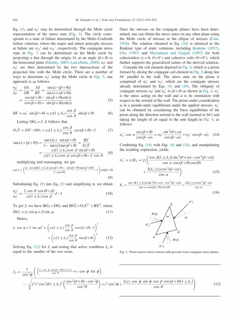
Fig. 4. Prism used to derive lateral earth pressure from conjugate stress planes.
M. Iskander et al. / Soils and Foundations 53 (2013) 639–652642
Eq. (4), and sβ 0 may be determined through the Mohr circlerepresentation of the stress state (Fig. 3). The circle corre-sponds to a state of failure determined by the Mohr–Coulombfailure criterion, where the major and minor principle stressesat failure are s1f 0 and s3f 0, respectively. The conjugate stressstate in Fig. 3 can be determined on the Mohr circle byprojecting a line through the origin, O, at an angle (βþθ) tothe horizontal plane (Murthy, 2003; Lancellotta, 2009). sθ 0 andsβ 0 are then determined by the two intersections of theprojected line with the Mohr circle. There are a number ofways to determine sβ 0 using the Mohr circle in Fig. 3; oneapproach is as follows:
sβ 0
sθ 0¼ OA
OB¼ AS
BS0¼ sin ðλ�ðβþθÞÞ
sin ðλþðβþθÞÞ¼ cos ðβþθÞ� sin ðβþθÞcotðλÞ
cos ðβþθÞþ sin ðβþθÞcotðλÞ ð5Þ
BS0 ¼ sθ 0 sin ðβþθÞ ¼ γzð17kvÞcos β
cos θsin ðβþθÞ ð6Þ
Letting OO1¼J, it follows that
O1S0 ¼OS0�OO1 ¼ γzð17kvÞ
cos β
cos θcos ðβþθÞ�J ð7Þ
tan ðλþðβþθÞÞ ¼ tan ðλÞþ tan ðβþθÞ1� tan ðλÞ tan ðβþθÞ ¼
BS0
O1S0
¼ γzð17kvÞ cos β sin ðβþθÞγzð17kvÞ cos β cos ðβþθÞ�J cos θ
ð8Þ
multiplying and rearranging, we get
cot λ¼ γz cos ðβÞð17kvÞð cos ðβþθÞþ sin ðβþθÞ tan ðβþθÞÞJ cos ðθÞ �1
� �cotðβþθÞ
ð9ÞSubstituting Eq. (9) into Eq. (5) and simplifying it, we obtain
sβ 0
sθ 0¼ 2 cos θ cos ðθþβÞ
γzð17kvÞ cos βJ�1 ð10Þ
To get J, we have BO1¼DO1 and BO12¼O1S'
2 þBS'2, where
DO1 ¼ ðc cot φþJÞ sin φ ð11ÞHence,
ðc cos φþJ sin φÞ2 ¼ γzð17kvÞcos β
cos θcos ðβþθÞ�J
� �2
þ γzð17kvÞcos β
cos θsin ðβþθÞ
� �2
ð12Þ
Solving Eq. (12) for J, and noting that active condition Ja isequal to the smaller of the two roots,
Ja ¼1
cos 2ϕγz cos β cos ðβþθÞð17 kvÞ
cos θ þc cos ϕ sin ϕ� ��
�ffiffiffiffiffiffiffiffiffiffiffiffiffiffiffiffiffiffiffiffiffiffiffiffiffiffiffiffiffiffiffiffiffiffiffiffiffiffiffiffiffiffiffiffiffiffiffiffiffiffiffiffiffiffiffiffiffiffiffiffiffiffiffiffiffiffiffiffiffiffiffiffiffiffiffiffiffiffiffiffiffiffiffiffiffiffiffiffiffiffiffiffiffiffiffiffiffiffiffiffiffiffiffiffiffiffiγ2z2 cos 2βð17kvÞ2
cos 2ðβþθÞ� cos 2ϕcos 2θ
� �þc2 cos 2ϕ
s
Once the stresses on the conjugate planes have been deter-mined, one can obtain the stress states on any other plane usingthe Mohr circle of stresses or the ellipse of stresses (Cain,1916). The solution obtained in Eq. (10) is identical to theRankine type of static solutions, including Rankine (1857),Chu (1991) and Mazindrani and Ganjali (1997) for bothcohesionless (c¼0, θ¼01) and cohesive soils (θ¼01), whichfurther supports the generalized nature of the derived solution.Consider the soil element depicted in Fig. 4, which is a prism
formed by slicing the conjugate soil element in Fig. 2 along linebb´ parallel to the wall. The stress state on the prism iscomprised of sθ 0 and sβ 0, which are the conjugate stressesalready determined by Eqs. (4) and (10). The obliquity ofconjugate stresses sθ 0 and sβ 0 is (βþθ) as shown in Fig. 4. sa0
is the stress acting on the wall and α is its orientation withrespect to the normal of the wall. The prism under considerationis in a pseudo-static equilibrium under the applied stresses. sa0
can be obtained by considering the force equilibrium of theprism along the direction normal to the wall (normal to bb') andtaking the length of ab equal to the unit length in Fig. 4, asfollows:
sa0 cos αcos ðβþθÞcos ðβ�ωÞ ¼ sθ 0
sin 2ðθþωÞcos ðβ�ωÞ þsβ 0 cos ðβ�ωÞ ð14Þ
Combining Eq. (14) with Eqs. (4) and (10), and manipulatingthe resulting expression, yields
sa0 ¼ γzKa ¼ γzcos βð17kvÞð sin 2ðθþωÞ� cos 2ðβ�ωÞÞ
cos α cos ðβþθÞ cos ðθÞ
�
þ 2ðJa=γzÞ cos 2ðβ�ωÞcos α
�ð15Þ
Ka ¼ cos βð17kvÞð sin 2ðθþωÞ� cos 2ðβ�ωÞÞcos α cos ðβþθÞ cos ðθÞ þ 2ðJa=γzÞ cos 2ðβ�ωÞ
cos α
ð16Þ
ffiffiffiffiffiffiffiffiffiffiffiffiffiffiffiffiffiffiffiffiffiffiffiffiffiffiffiffiffiffiffiffiffiffiffiffiffiffiffiffiffiffiffiffiffiffiffiffiffiffiffiffiffiffiffiffiffiffiffiffiffiffiffiffiffiffiffiffiffiffiffiffiffiffiffiffiffiffiffiffiffiffiffiffiffiffiffiffiffiffiþ 2cγz cos ϕ sin ϕ cos β cos ðβþθÞð17kvÞ
cos θ
!ð13Þ
M. Iskander et al. / Soils and Foundations 53 (2013) 639–652 643
The obliquity of the earth thrust, αa, can be obtained byconsidering the equilibrium of the prism in the vertical direction,as follows:
sa0 sin αcos ðβþθÞcos ðβ�ωÞ ¼ sθ 0
cos ðθþωÞ sin ðθþωÞcos ðβ�ωÞ þsβ 0 sin ðβ�ωÞ ð17Þ
αa is assumed to be constant in most earth pressure solutions (e.g., Coulomb assumes α=δ=2/3φ). The obliquity can becalculated in the proposed formulation by dividing Eq. (17)by Eq. (14) yielding αa for the active condition as
αa ¼ tan�1
2 cos θ cos ðβþθÞcos βð17 kvÞ
Jaγz�1
� �sin 2ðβ�ωÞþ sin 2ðθþωÞ
2 2 cos θ cos ðβþ θÞcos βð17 kvÞ
Jaγz�1
� �cos 2ðβ�ωÞþ sin 2ðθþωÞ
� �0@
1Að18Þ
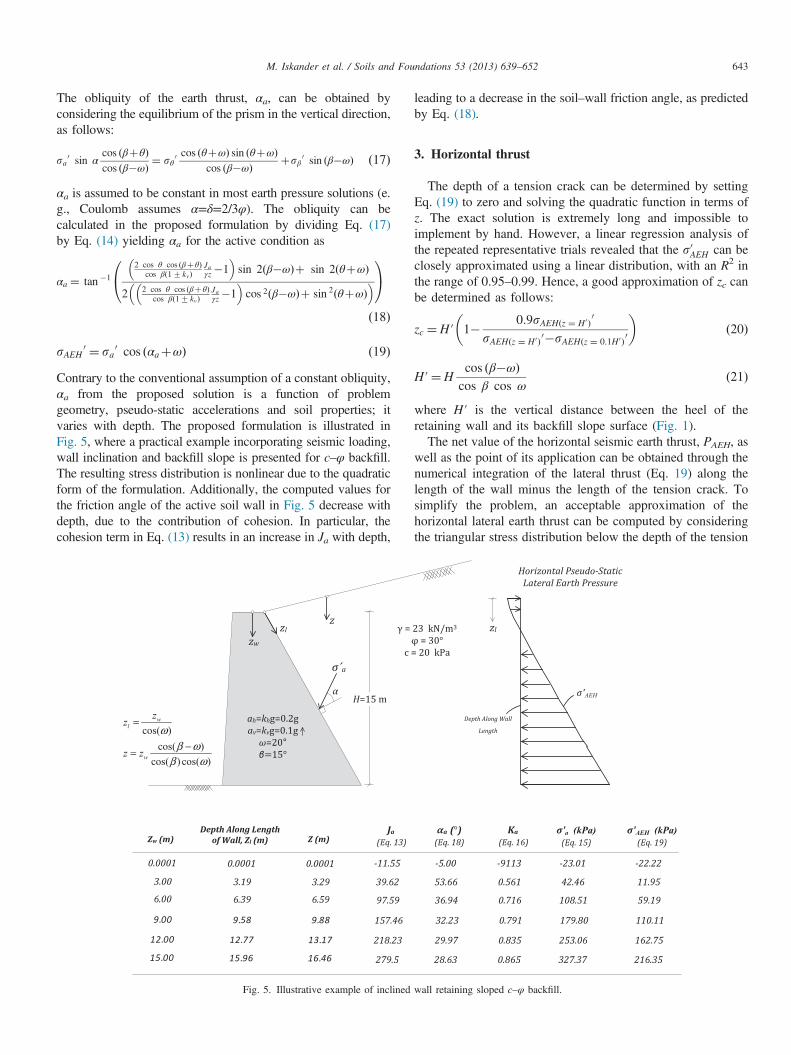
sAEH 0 ¼ sa0 cos ðαaþωÞ ð19ÞContrary to the conventional assumption of a constant obliquity,αa from the proposed solution is a function of problemgeometry, pseudo-static accelerations and soil properties; itvaries with depth. The proposed formulation is illustrated inFig. 5, where a practical example incorporating seismic loading,wall inclination and backfill slope is presented for c–φ backfill.The resulting stress distribution is nonlinear due to the quadraticform of the formulation. Additionally, the computed values forthe friction angle of the active soil wall in Fig. 5 decrease withdepth, due to the contribution of cohesion. In particular, thecohesion term in Eq. (13) results in an increase in Ja with depth,
Fig. 5. Illustrative example of inclined
leading to a decrease in the soil–wall friction angle, as predictedby Eq. (18).
3. Horizontal thrust
The depth of a tension crack can be determined by settingEq. (19) to zero and solving the quadratic function in terms ofz. The exact solution is extremely long and impossible toimplement by hand. However, a linear regression analysis ofthe repeated representative trials revealed that the s0AEH can beclosely approximated using a linear distribution, with an R2 inthe range of 0.95–0.99. Hence, a good approximation of zc canbe determined as follows:
zc ¼H′ 1� 0:9sAEHðz ¼ H0Þ0
sAEHðz ¼ H0Þ0�sAEHðz ¼ 0:1H0Þ0
� �ð20Þ
H′¼Hcos ðβ�ωÞcos β cos ω
ð21Þ
where H′ is the vertical distance between the heel of theretaining wall and its backfill slope surface (Fig. 1).The net value of the horizontal seismic earth thrust, PAEH, as
well as the point of its application can be obtained through thenumerical integration of the lateral thrust (Eq. 19) along thelength of the wall minus the length of the tension crack. Tosimplify the problem, an acceptable approximation of thehorizontal lateral earth thrust can be computed by consideringthe triangular stress distribution below the depth of the tension
wall retaining sloped c–φ backfill.
M. Iskander et al. / Soils and Foundations 53 (2013) 639–652644
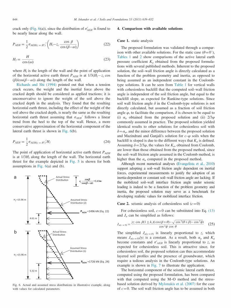
crack only (Fig. 6(a)), since the distribution of s0AEH is found tobe nearly linear along the wall.
PAEH ¼ 12sAEHðz ¼ H0Þ
0 Hl�zccos β
cos ðβ�ωÞ
� �ð22Þ
Hl ¼H
cos ðωÞ ð23Þ
where Hl is the length of the wall and the point of applicationof the horizontal active earth thrust PAEH is at 1/3(Hl�zc cos(β)/cos(β�ω)) along the length of the wall.
Richards and Shi (1994) pointed out that when a tensioncrack occurs, the weight and the inertial force above thecracked depth should be considered as applied tractions; it isunconservative to ignore the weight of the soil above thecracked depth in the analysis. They found that the resultinghorizontal earth thrust, including the effect of the weight of thesoil above the cracked depth, is nearly the same as the resultinghorizontal earth thrust assuming that sAEH 0 follows a lineartrend from the heel to the top of the wall. Hence, a moreconservative approximation of the horizontal component of thelateral earth thrust is shown in Fig. 6(b).
PAEH ¼ 12sAEHðz ¼ H0Þ
0Hl ð24Þ
The point of application of horizontal active earth thrust PAEH
is at 1/3Hl along the length of the wall. The horizontal earththrust for the example depicted in Fig. 5 is shown for bothassumptions in Fig. 6(a) and (b).
Fig. 6. Actual and assumed stress distributions in illustrative example, alongwith values for calculated parameters.
4. Comparison with available solutions
Case 1. static analysis
The proposed formulation was validated through a compar-ison with other available solutions. For the static case (θ¼01),Tables 1 and 2 show comparisons of the active lateral earthpressure coefficient Ka obtained from the proposed formula-tions with several published methods. Inherent to the proposedsolution, the soil–wall friction angle is directly calculated as afunction of the problem geometry and inertia, as opposed tobeing assumed as an independent constant in the Coulomb-type solutions. It can be seen from Table 1 for vertical wallswith cohesionless backfill that the computed soil–wall frictionangle is independent of the soil friction angle, but equal to thebackfill slope, as expected for Rankine-type solutions. Sincesoil wall friction angle δ in the Coulomb-type solutions is notdirectly calculated, but assumed as a fraction of soil frictionangle φ, to facilitate the comparison, δ is chosen to be equal to(i) αa obtained from the proposed solution and (ii) 2/3φcommonly assumed in practice. The proposed solution yieldedidentical results to other solutions for cohesionless soil withδ¼αa, and the minor difference between the proposed solutionand Mazindrani and Ganjali's solution for c–φ soils when thebackfill is sloped is due to the different ways that Ka is defined.Assuming δ¼2/3φ, the values for Ka, obtained from Coulomb,are lower than those obtained from the proposed method, sincethe soil–wall friction angle assumed in the Coulomb method, ishigher than the αa computed in the proposed method.Although recent numerical analyses (Evangelista et al., 2010)
support adopting a soil–wall friction angle dependent on inertialforces, experimental measurements to justify the adoption of aninertia-dependent or constant soil–wall friction angle are lacking. Ifthe mobilized soil–wall interface friction angle under seismicloading is indeed to be a function of the problem geometry andinertia, the proposed solution may serve as a benchmark fordeveloping realistic values for mobilized interface friction.
Case 2. seismic analysis of cohesionless soil (c¼0)
For cohesionless soil, c¼0 can be substituted into Eq. (13)and Ja can be simplified as follows:
Jaðc ¼ 0Þ ¼ γz cos βð17kvÞð cos ðβþθÞ�ffiffiffiffiffiffiffiffiffiffiffiffiffiffiffiffiffiffiffiffiffiffiffiffiffiffiffiffiffiffiffiffiffiffiffiffiffiffiffifficos 2ðθþβÞ� cos 2ϕ
pÞ
cos 2ϕ cos θð25Þ
The simplified Ja(c¼0) is linearly proportional to z, whichmeans Ja(c¼0)/γz is a constant. As a result, both αa and Ka
become constants and s'AEH is linearly proportional to z, asexpected for cohesionless soil. This is attractive since, forcohesionless soil, the proposed solution can thus accommodatelayered soil profiles and the presence of groundwater, whichrequire a tedious analysis in the Coulomb-type solutions. Anexample is shown in Fig. 7 to illustrate the application.The horizontal component of the seismic lateral earth thrust,
computed using the proposed formulation, has been comparedwith that computed using the M–O method and the stress-based solution derived by Mylonakis et al. (2007) for the caseof c¼0. The soil wall friction angle has to be assumed in both
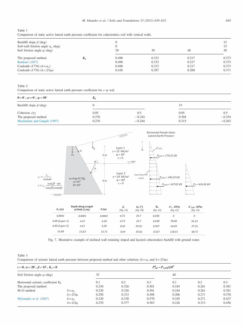
Fig. 7. Illustrative example of inclined wall retaining sloped and layered cohesionless backfill with ground water.
Table 1Comparison of static active lateral earth pressure coefficient for cohesionless soil with vertical walls.
Backfill slope β (deg) 0 15Soil-wall friction angle αa (deg) 0 15Soil friction angle φ (deg) 20 30 40 30
The proposed method Ka 0.490 0.333 0.217 0.373Rankine (1857) 0.490 0.333 0.217 0.373Coulomb (1776) (δ¼αa) 0.490 0.333 0.217 0.373Coulomb (1776) (δ¼2/3φ) 0.438 0.297 0.200 0.371
Table 3Comparison of seismic lateral earth pressure between proposed method and other solutions (δ¼αa and δ¼2/3φ).
c¼0, ω¼201, β¼151, Kv¼0 PnAE¼PAEH/γH
2
Soil friction angle φ (deg) 35 40
Horizontal seismic coefficient Kh 0.1 0.2 0.3 0.1 0.2 0.3The proposed method 0.230 0.326 0.501 0.184 0.261 0.381M–O method δ¼αa 0.230 0.326 0.501 0.184 0.261 0.381
δ¼2/3φ 0.250 0.333 0.498 0.206 0.271 0.378Mylonakis et al. (2007) δ¼αa 0.230 0.338 0.570 0.185 0.271 0.427
δ¼2/3φ 0.270 0.377 0.583 0.226 0.313 0.456
Table 2Comparison of static active lateral earth pressure coefficient for c–φ soil.
θ¼01, ω¼01, φ¼301 Ka
Backfill slope β (deg) 0 15
Cohesion c/γz 0.05 0.5 0.05 0.5The proposed method 0.276 �0.244 0.304 �0.254Mazindrani and Ganjali (1997) 0.276 �0.244 0.315 �0.263
M. Iskander et al. / Soils and Foundations 53 (2013) 639–652 645
M. Iskander et al. / Soils and Foundations 53 (2013) 639–652646
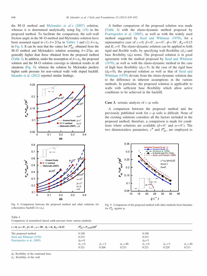
the M–O method and Mylonakis et al.'s (2007) solution,whereas it is determined analytically using Eq. (18) in theproposed method. To facilitate the comparison, the soil–wallfriction angle in the M–O method and Mylonakis solution havebeen assumed equal to (1) δ¼2/3φ in Tables 3 and (2) δ¼αain Fig. 8. It can be seen that the values for Pn
AE , obtained from theM–O method and Mylonakis's solution assuming δ¼2/3φ, aregenerally higher than those obtained from the proposed method(Table 3). In addition, under the assumption of δ¼αa, the proposedsolution and the M–O solution converge to identical results in allsituations (Fig. 8), whereas the solution by Mylonakis predictshigher earth pressure for non-vertical walls with sloped backfill.Iskander et al. (2012) reported similar findings.
Fig. 8. Comparison between the proposed method and other solutions forcohesionless backfill (δ¼αa).
Table 4Comparison of normalized lateral earth pressure from various methods.
c¼0, ω¼01, β¼01, φ¼301, Kv¼0, Kh¼0.15 PnAE¼PAEH/γH
2
The proposed method 0.190Seed and Whitman (1970) 0.223Psarropoulos et al. (2005) dθ¼0
dw¼0 dw¼0.321 0.26
dθ: flexibility of the rotational base.dw: flexibility of the wall.
A further comparison of the proposed solution was made(Table 4) with the elasto-dynamic method proposed byPsarropoulos et al. (2005), as well as with the widely usedmethod suggested by Seed and Whitman (1970), for arepresentative case of c¼0, β¼01, ω¼01, ϕ¼301, Kh¼0.15and Kv¼0. The elasto-dynamic solution can be applied to bothrigid and flexible walls, by specifying wall flexibility (dw) andbase flexibility (dθ) terms. The proposed solution is in goodagreement with the method proposed by Seed and Whitman(1970), as well as with the elasto-dynamic method in the caseof high base flexibility (dθ¼5). In the case of the rigid base(dθ¼0), the proposed solution as well as that of Seed andWhitman (1970) deviate from the elasto-dynamic solution dueto the difference in inherent assumptions in the variousmethods. In particular, the proposed solution is applicable towalls with sufficient base flexibility which allow activeconditions to be achieved in the backfill.
Case 3. seismic analysis of c–φ soils
A comparison between the proposed method and thepreviously published work for c–φ soils is difficult. None ofthe existing solutions considers all the factors included in theproposed method; therefore, a comparison is made for condi-tions where solutions are available (β¼01 and ω¼01). Thetwo dimensionless parameters, cn and Pn
AE , are employed to
0.1900.223dθ¼5
5 dw¼40 dw¼0 dw¼5 dw¼408 0.233 0.221 0.220 0.213
Fig. 9. Comparison of the proposed method with other methods from literaturefor Pn
AE against φ.
M. Iskander et al. / Soils and Foundations 53 (2013) 639–652 647
facilitate comparisons as follows:
cn ¼ c
γHð26Þ
Pn
AE ¼PAEH
γH2 ð27Þ
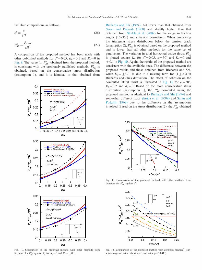
A comparison of the proposed method has been made withother published methods for cn¼0.05, Kh¼0.1 and Kv¼0 inFig. 9. The value for Pn
AE, obtained from the proposed method,is consistent with the previously published methods. Pn
AE isobtained, based on the conservative stress distribution(assumption 1), and it is identical to that obtained from
Fig. 10. Comparison of the proposed method with other methods fromliterature for Pn
AE against Kh for Kv¼0 and Kv¼70.1.
Richards and Shi (1994), but lower than that obtained fromSaran and Prakash (1968) and slightly higher than thatobtained from Shukla et al. (2009) for the range in frictionangles (15–351) and cohesion considered. When employingthe triangular stress distribution below the tension crack(assumption 2), Pn
AE is obtained based on the proposed methodand is lower than all other methods for the same set ofparameters. The variation in total horizontal active thrust Pn
AEis plotted against Kh for cn¼0.05, φ¼301 and Kv¼0 and70.1 in Fig. 10. Again, the results of the proposed method areconsistent with the available ones. The difference between theproposed results and those obtained from Richards and Shi,when Kv¼70.1, is due to a missing term for (17Kv) inRichards and Shi's derivation. The effect of cohesion on thecomputed lateral thrust is illustrated in Fig. 11 for φ¼301,Kh¼0.2 and Kv¼0. Based on the more conservative stressdistribution (assumption 1), the Pn
AE computed using theproposed method is identical to Richards and Shi (1994) andsomewhat different from Shukla et al. (2009) and Saran andPrakash (1968) due to the difference in the assumptionsinvolved. Based on the stress distribution (2), the Pn
AE obtained
Fig. 11. Comparison of the proposed method with other methods fromliterature for Pn
AE against cn.
Fig. 12. Comparison of the proposed method with common practicen (sub-stitute c–φ soil with cohesionless soil with φ¼33.411).
M. Iskander et al. / Soils and Foundations 53 (2013) 639–652648
from the present study is lower than all other methods, exceptwhen cn is greater than 0.15 where it is higher than that ofShukla et al. (2009). Huntington (1957) noted: “For manyyears it was almost universal practice to compute the earthpressure against a retaining wall on the assumption that thesoil was cohesionless and that the value of φ could beconsidered equivalent to the angle of repose…. The mostcommon assumption according to this practice was that theslope of the angle of repose was 1.5 horizontal: 1 Vertical” (i.e., 33.41). Fig. 12 shows that the aforementioned practice leadsto the significant overdesign for low walls and under-designfor high walls.
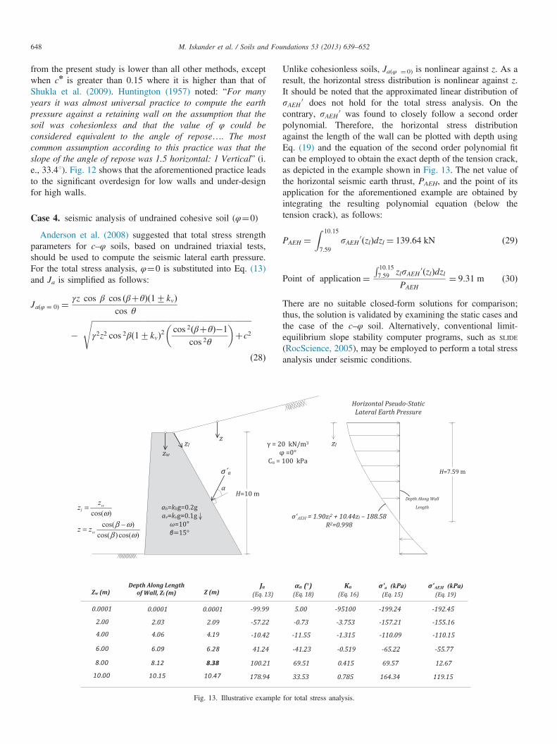
Case 4. seismic analysis of undrained cohesive soil (φ¼0)
Anderson et al. (2008) suggested that total stress strengthparameters for c–φ soils, based on undrained triaxial tests,should be used to compute the seismic lateral earth pressure.For the total stress analysis, φ¼0 is substituted into Eq. (13)and Ja is simplified as follows:
Jaðφ ¼ 0Þ ¼γz cos β cos ðβþθÞð17kvÞ
cos θ
�ffiffiffiffiffiffiffiffiffiffiffiffiffiffiffiffiffiffiffiffiffiffiffiffiffiffiffiffiffiffiffiffiffiffiffiffiffiffiffiffiffiffiffiffiffiffiffiffiffiffiffiffiffiffiffiffiffiffiffiffiffiffiffiffiffiffiffiffiffiffiffiffiffiffiffiffiffiffiffiffiffiffiγ2z2 cos 2βð17kvÞ2 cos 2ðβþθÞ�1
cos 2θ
� �þc2
s
ð28Þ
Fig. 13. Illustrative example
Unlike cohesionless soils, Ja(φ ¼0) is nonlinear against z. As aresult, the horizontal stress distribution is nonlinear against z.It should be noted that the approximated linear distribution ofsAEH 0 does not hold for the total stress analysis. On thecontrary, sAEH 0 was found to closely follow a second orderpolynomial. Therefore, the horizontal stress distributionagainst the length of the wall can be plotted with depth usingEq. (19) and the equation of the second order polynomial fitcan be employed to obtain the exact depth of the tension crack,as depicted in the example shown in Fig. 13. The net value ofthe horizontal seismic earth thrust, PAEH, and the point of itsapplication for the aforementioned example are obtained byintegrating the resulting polynomial equation (below thetension crack), as follows:
PAEH ¼Z 10:15
7:59sAEH 0ðzlÞdzl ¼ 139:64 kN ð29Þ
Point of application¼R 10:157:59 zlsAEH 0ðzlÞdzl
PAEH¼ 9:31 m ð30Þ
There are no suitable closed-form solutions for comparison;thus, the solution is validated by examining the static cases andthe case of the c–φ soil. Alternatively, conventional limit-equilibrium slope stability computer programs, such as SLIDE
(RocScience, 2005), may be employed to perform a total stressanalysis under seismic conditions.
for total stress analysis.
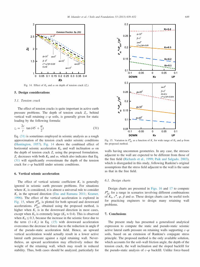
Fig. 15. Variation in PnAE as a function of Kv for wide range of Kh and φ from
the proposed method.
Fig. 14. Effect of Kh and ω on depth of tension crack (Zc).
M. Iskander et al. / Soils and Foundations 53 (2013) 639–652 649
5. Design considerations
5.1. Tension crack
The effect of tension cracks is quite important in active earthpressure problems. The depth of tension crack Zc, behindvertical wall retaining c–φ soils, is generally given for staticloading by the following formula:
zc ¼2cγ
tan ð451þ φ
2Þ ð31Þ
Eq. (31) is sometimes employed in seismic analysis as a roughapproximation of the tension crack under seismic conditions(Huntington, 1957). Fig. 14 shows the combined effect ofhorizontal seismic acceleration Kh and wall inclination ω onthe depth of tension crack Zc using the proposed formulation.Zc decreases with both Kh and ω, which also indicates that Eq.(31) will significantly overestimate the depth of the tensioncrack for c–φ backfill under seismic conditions.
6. Vertical seismic acceleration
The effect of vertical seismic coefficient Kv is generallyignored in seismic earth pressure problems. For situationswhere Kv is considered, it is almost a universal rule to considerKv in the upward direction (Das and Ramana 2011; Kramer,1996). The effect of the vertical acceleration is explored inFig. 15, where Pn
AE is plotted for both upward and downwardaccelerations. Pn
AE, obtained using the proposed method, ishigher when Kv is in the downward direction in most cases,except when Kh is extremely large (KhE0.4). This is observedwhen Khr0.3, because the increase in the seismic force due tothe term (1þKv) in Eq. (15) with downward accelerationovercomes the decrease in force due to the reduction in angle θof the pseudo-static acceleration field. Hence, an upwardvertical acceleration would actually result in a lower activelateral earth pressure against a rigid retaining wall. Never-theless, an upward acceleration may effectively reduce theweight of the retaining wall, which may result in reducedstability. Thus, both cases should be analyzed, particularly for
walls having uncommon geometries. In any case, the stressesadjacent to the wall are expected to be different from those ofthe free field (Richards et al., 1999; Paik and Salgado, 2003),which is disregarded in this study, following Rankine's originalassumptions that the stress field adjacent to the wall is the sameas that in the free field.
6.1. Design charts
Design charts are presented in Figs. 16 and 17 to computePnAE for a range in scenarios involving different combinations
of Kh, cn, φ, β and ω. These design charts can be useful tools
for practicing engineers to design many retaining wallproblems.
7. Conclusions
The present study has presented a generalized analyticalexpression to compute the static and pseudo-static seismicactive lateral earth pressure on retaining walls supporting c–φsoils, based on an extension of Rankine's conjugate stressprinciple. The proposed method is the only available solution,which accounts for the soil–wall friction angle, the depth of thetension crack, the wall inclination and the sloped backfill forthe pseudo-static analysis of c–φ backfill. Unlike force-based
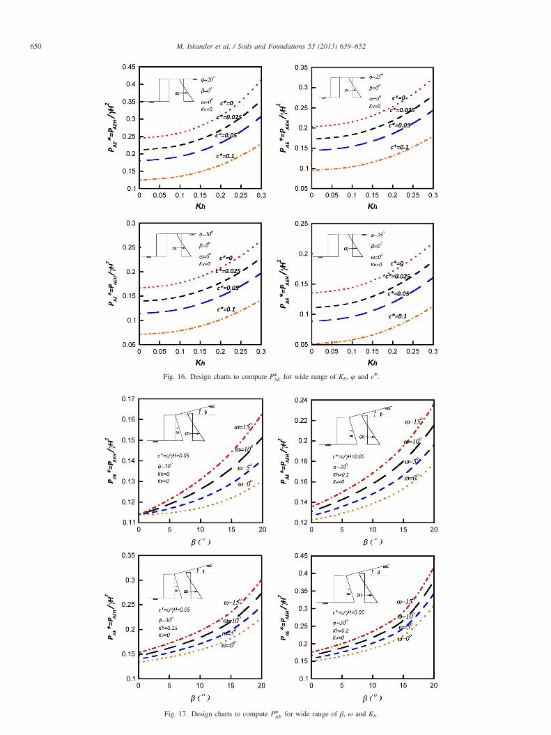
Fig. 17. Design charts to compute PnAE for wide range of β, ω and Kh.
Fig. 16. Design charts to compute PnAE for wide range of Kh, φ and cn.
M. Iskander et al. / Soils and Foundations 53 (2013) 639–652650
M. Iskander et al. / Soils and Foundations 53 (2013) 639–652 651
methods, the proposed method provides a stress-based solutionwhere the distribution of the net active thrust is easilyobtained. The results from the proposed formulation comparefavorably with existing methods for situations where acomparison is feasible. In addition, both depth of the tensioncrack and the soil–wall friction angle are calculated directlywithin the proposed expressions, whereas they must beapproximated or assumed in most formulations. Design chartshave been presented to calculate the net active horizontal thrustfrom c–φ backfill on retaining walls for different scenarios.
Acknowledgments
The authors gratefully acknowledge the support of theDefense Threat Reduction Agency (DTRA) Grant no.HDTRA1-10-1-0049 and the National Science Foundation(NSF) grant DGE 0741714.
Appendix
Nomenclature
ah horizontal accelerationav vertical accelerationkh horizontal seismic coefficientkv vertical seismic coefficientαa active soil–wall friction angle in the proposed methodβ backfill surface slopeδ soil wall friction angle in Mononobe–Okabe methodγ soil unit weightγθ soil unit weight in the direction of zθ (see Fig. 1)θ orientation of the pseudo-static acceleration field (see
Fig. 1)φ soil internal friction anglec soil cohesionω wall inclination with respect to the verticalg gravitational accelerationgθ resultant of the gravitational acceleration and pseudo-
static vertical and horizontal acceleration (see Fig. 1)H wall heightHl wall lengthH' distance between heel of retaining wall and its backfill
slope (see Fig. 1)Ja simplifying term for active lateral earth pressureKa active seismic lateral earth pressure coefficientsa0 resultant stress acting on soil prism adjacent to wall
(see Fig. 4)W weight of soil over conjugate stress elementsβ 0 lateral component of effective stress on conjugate
stress element parallel to backfill slope surface (seeFig. 2)
sθ 0 conjugate component of effective stress on conjugatestress element along θ axis (see Fig. 2)
s1f 0 major principle stress at failure under active condi-tions (see Fig. 3)
s3f 0 minor principle stress at failure under active condi-tions (see Fig. 3)
z vertical depth of soil element from backfill surfacezl vertical depth along wall lengthzw vertical depth from top of wall surfacezθ Z axis direction rotated clockwise to angle of θ
References
Al-Homoud, A.S., Whitman, R.V., 1994. Comparison between FE predictionand results from dynamic centrifuge tests on tilting gravity walls. SoilDynamics and Earthquake Engineering 14 (323), 259–268.
Anderson, D.G., Martin, G.R., Lam, I.P., Wang, J.N., 2008. Seismic Designand Analysis of Retaining Walls, Buried Structures, Slopes and Embank-ments, NCHRP Report 611. Transportation Research Board, NationalCooperative Highway Research Program, Washington DC.
Cain, W., 1916. Earth Pressure, Retaining Walls and Bins, John Wiley andSons, New York. Available from: ⟨books.google.com⟩ (accessed03.07.11.).
Caquot, A., Kerisel, J., 1948. Tables for the Calculation of the PassivePressure, Active Pressure and Bearing Capacity of Foundations. Gauthier-Villars, Paris.
Chu, S.C., 1991. Rankine's analysis of active and passive pressures in drysands. Soils and Foundations 31 (4), 115–120.
Das, B.M., Ramana, G.V., 2011. Principles of Soil Dynamics. SengageLearning, Stamford, CT.
Evangelista, A., Santolo, A.S., Simonelli, A.L., 2010. Evaluation of pseudo-static active earth pressure coefficient of cantilever retaining walls. SoilDynamics and Earthquake Engineering 30, 1119–1128.
Gazetas, G., Psarropoulos, P.N., Anastasapoulos, I., Gerolymos, N., 2004. Soilbehavior of flexible retaining systems subjected to short-duration moder-ately strong excitation. Soil Dynamics and Earthquake Engineering 24,537–550.
Ghosh, S., Sharma, R.P., 2010. Pseudo-dynamic active response of non-vertical retaining wall supporting c–φ backfill. Geotechnical and Geologi-cal Engineering 28 (5), 633–641.
Habibagahi, K., Ghahramani, A., 1979. Zero extension line theory of earthpressure. Journal of the Geotechnical Engineering Division, ASCE 105(GT7), 881–896.
Heyman, J., 1997. Coulomb's Memoir on Statics: An Essay in the History ofCivil Engineering. Imperial College Press, London.
Huntington, W.C., 1957. Earth Pressures and Retaining Walls. John Wiley andSons, New York.
Iskander, M., Omidvar, M., Elsherif, O., 2012. Conjugate stress approach forRankine seismic active earth pressure in cohesionless soils. Journal ofGeotechnical and Geoenvironmental Engineering 139 (7), 1205–1210.
Koseki, J., Hong, K., Nakajima, S., Mulmi, S., Watanabe, K., Tateyama, M.,2010. Negative pore air pressure generation in backfill of retaining wallsduring earthquakes and its effect on seismic earth pressure. Soils andFoundations 50 (5), 747–755.
Kramer, S.L., 1996. Geotechnical Earthquake Engineering. Prentice Hall, NewJersey.
Lancellotta, R., 2007. Lower-bound approach for seismic passive earthresistance. Geotechnique 57 (3), 319–321.
Lancellotta, R., 2009. Geotechnical Engineering, second ed. Taylor & Francis,New York.
Lew, M., Sitar, N., Al Atik, L., Pourzanjani, M., Hudson, M.B., 2010a.Seismic earth pressure on deep building basements. In: Proceedings of theAnnual Convention 2010, Structural Engineers Association of California.
Lew, M., Sitar, N., Al Atik, L., 2010b. Seismic earth pressures: fact or fiction.Invited Keynote Paper. In: Proceedings of Earth Retention Conference, ER2010, ASCE, Seattle.
Madabhushi, S.P.G., Zeng, X., 2007. Simulating seismic response of cantileverretaining walls. Journal of Geotechnical and Geoenvironmental Engineer-ing 133 (5), 539–549.
M. Iskander et al. / Soils and Foundations 53 (2013) 639–652652
Mazindrani, Z.H., Ganjali, M.H., 1997. Lateral earth pressure problem ofcohesive backfill with inclined surface. Journal of Geotechnical andGeoenvironmental Engineering 123 (2), 110–112.
Mononobe, N., Matsuo, M., 1932. Experimental Investigation of Lateral EarthPressure During Earthquakes. Earthquake Research Institute and ResearchOffice of Public Works, pp. 884–902.
Mononobe, N., Matsuo, O., 1929. On the determination of earth pressureduring earthquakes. In: Proceeding of the World Engineering Congress,vol. 9, Tokyo, Japan, pp. 179–187.
Mylonakis, G., Kloukinas, P., Papantonopoulos, C., 2007. An alternative to theMononobe–Okabe equations for seismic earth pressures. Soil Dynamicsand Earthquake Engineering 27, 957–969.
Murthy, V.N.S., 2003. Geotechnical Engineering: Principles and Practices ofSoil Mechanics and Foundation Engineering. Marcel Dekker, New York.
Nakamura, S., 2006. Reexamination of Mononobe–Okabe theory of gravityretaining walls using centrifuge model tests. Soils and Foundations 46 (2),135–146.
Okabe, S., 1924. General theory on earth pressure and seismic stability ofretaining walls and dams. Journal of Japanese Society of Civil Engineers10 (6), 1277–1323.
Paik, K.H., Salgado, R., 2003. Estimation of active earth pressure against rigidretaining walls considering arching effects. Geotechnique 53 (7), 643–653.
Psarropoulos, P.N., Klonaris, G., Gazetas, G., 2005. Seismic earth pressures onrigid and flexible earth retaining walls. Soil Dynamics and EarthquakeEngineering 25, 795–809.
Rankine, W.J.M., 1857. On the stability of loose earth. PhilosophicalTransactions of the Royal Society of London 147, 9–27.
Rankine, W.J.M., 1858. A Manual of Applied Mechanics, Glasgow UniversityPress. Available from: ⟨books.google.com⟩ (accessed 03.07.11.).
Richards, R., Shi, X., 1994. Seismic lateral pressures in soils with cohesion.Journal of Geotechnical Engineering 120 (7), 1230–1251.
Richards, R., Huang, C., Fishman, K.L., 1999. Seismic earth pressure onretaining structures. Journal of Geotechnical and Geoenvironmental Engi-neering 125 (9), 771–778.
RocScience, 2005. Slide: Stability Analysis for Soil and Rock Slopes. ⟨www.rocscience.com⟩.
Saran, S., Gupta, R.P., 2003. Seismic earth pressures behind retaining walls.Indian Geotechnical Journal 33 (3), 195–213.
Saran, S., Prakash, S., 1968. Dimensionless parameters for static and dynamic earthpressures behind retaining walls. Indian Geotechnical Journal 7 (3), 295–310.
Seed, H.B., Whitman, R.V., 1970. Design of earth retaining structures fordynamic loads. In: Proceedings of the Specialty Conference on LateralStresses in the Ground and Design of Earth Retaining Structures, ASCE.
Shukla, S.J., Gupta, S.K., Sivakugan, N., 2009. Active earth pressure onretaining wall for c–φ soil backfill under seismic loading conditions. Journalof Geotechnical and Geoenvironmental Engineering 135 (5), 690–696.
Sitar, N., Mikola R., Candia, G., 2012. Seismically induced lateral earthpressure on retaining structures and basement walls. In: Proceedings ofGSP no. 226, pp. 335–358.
Sokolovskii, V.V., 1965. Statics of Granular Media. Pergamon Press, New York.Tiznado, J.C., Rodriguez-Roa, F., 2011. Seismic lateral movement prediction
for gravity retaining walls on granular soils. Soil Dynamics and EarthquakeEngineering 31, 391–400.
Watanabe, K., Koseki, J., Tateyama, M., 2011. Seismic earth pressure exertedon retaining walls under a large seismic load. Soils and Foundations 51 (3),379–394.
Wood, de V., 1876. The Elements of Analytical Mechanics, John Wiley andSons, New York. Available from: ⟨books.google.com⟩ (accessed 03.07.11.).


![Author's personal copyscholar.cu.edu.eg/?q=nehalafifi/files/17.pdf · 2021. 2. 13. · cosmetic formulations using HPLC were reported in the literatures [2527, ]. Pedro et al. validated](https://static.fdocument.org/doc/165x107/6125901cc49ed829027bd4cd/authors-personal-2021-2-13-cosmetic-formulations-using-hplc-were-reported.jpg)

![FurtherStudiesonAntioxidantPotentialandProtectionof ...downloads.hindawi.com/journals/jdr/2007/015803.pdf · formulations [13, 14]. Ayurveda also describes vidanga as pungent and](https://static.fdocument.org/doc/165x107/5e983cb5ea21fc1c66732cb3/furtherstudiesonantioxidantpotentialandprotectionof-formulations-13-14-ayurveda.jpg)