Accelerators Ideal Case
18
Accelerators Ideal Case Goal of an accelerator: increase energy of CHARGED par:cles • Increase energy • The par:cle trajectory direc:on dr parallel to v • …increase of energy with electric fields • Magne:c fields are used for control of trajectories ΔE = Fd r r 1 r 2 ∫ = q ( E + v × B ) d r r 1 r 2 ∫ ΔE = ! Fd ! r ! r 1 ! r 2 ∫ = q ! Ed ! r = qU ! r 1 ! r 2 ∫
Transcript of Accelerators Ideal Case
AcceleratorsIdealCase
Goalofanaccelerator:increaseenergyofCHARGEDpar:cles
• Increaseenergy
• Thepar:cletrajectorydirec:ondrparalleltov
• …increaseofenergywithelectricfields• Magne:cfieldsareusedforcontroloftrajectories
ΔE =F dr
r1
r2
∫ = q (E + v ×
B)dr
r1
r2
∫
ΔE =!F d!r!r1
!r2
∫ = q!Ed!r = qU!r1
!r2
∫
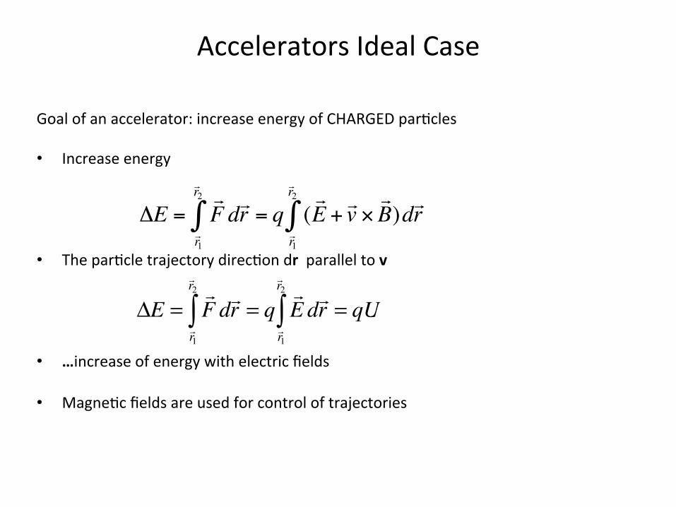
Energyvsvelocity
• Accelera:onincreasesvelocityofapar:cleatsmallβ=v/c.• Forhighβvelocitydoesnotchange.Thereisachangeofmomentum/
energythatcanbeexpressedasachangeofeffec:vemass
γ =EE0
=mm0
Par'clerestmass:electron0.511MeVproton938MeV239U~220000MeV
1GeV1MeV
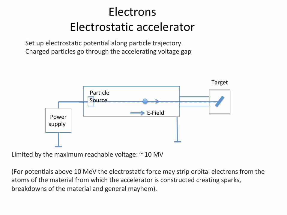
ElectronsElectrostaticaccelerator
Setupelectrosta:cpoten:alalongpar:cletrajectory.Chargedparticlesgothroughtheacceleratingvoltagegap
Limitedbythemaximumreachablevoltage:~10MV(Forpoten:alsabove10MeVtheelectrosta:cforcemaystriporbitalelectronsfromtheatomsofthematerialfromwhichtheacceleratorisconstructedcrea:ngsparks,breakdownsofthematerialandgeneralmayhem).
T
Powersupply
E---Field
Par:cleSource
Target
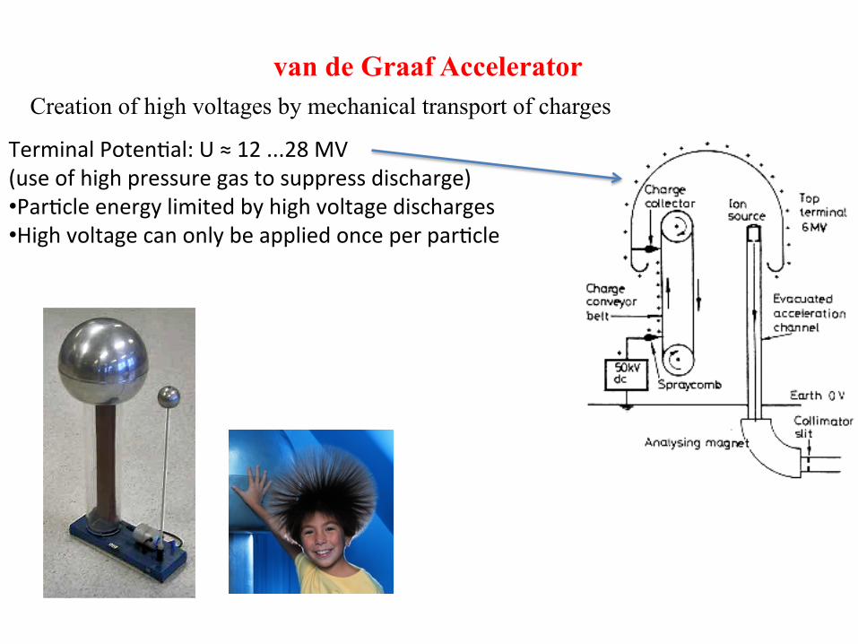
van de Graaf Accelerator Creation of high voltages by mechanical transport of charges
TerminalPoten:al:U≈12...28MV(useofhighpressuregastosuppressdischarge)• Par:cleenergylimitedbyhighvoltagedischarges• Highvoltagecanonlybeappliedonceperpar:cle
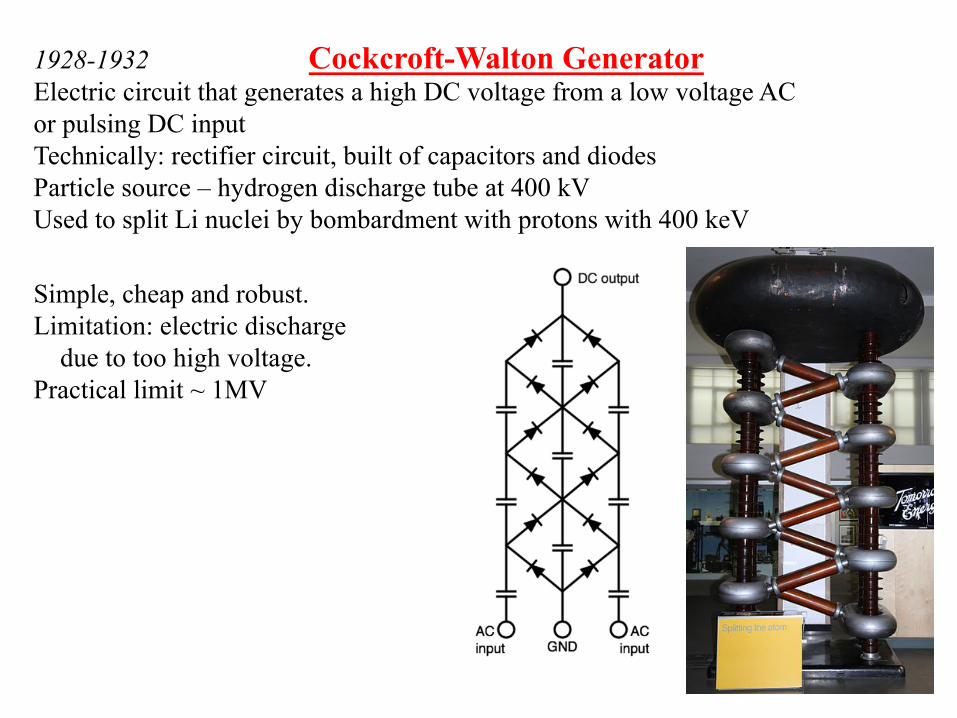
1928-1932 Cockcroft-Walton Generator Electric circuit that generates a high DC voltage from a low voltage AC or pulsing DC input Technically: rectifier circuit, built of capacitors and diodes Particle source – hydrogen discharge tube at 400 kV Used to split Li nuclei by bombardment with protons with 400 keV Simple, cheap and robust. Limitation: electric discharge due to too high voltage. Practical limit ~ 1MV
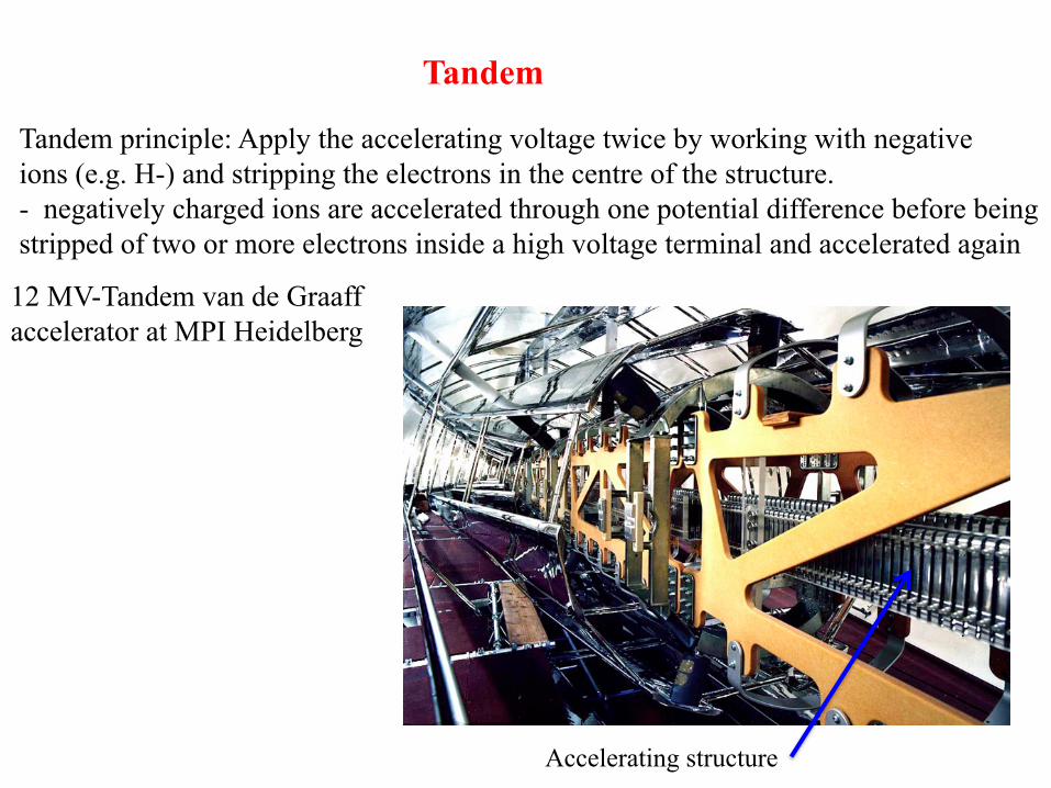
Tandem
Tandem principle: Apply the accelerating voltage twice by working with negative ions (e.g. H-) and stripping the electrons in the centre of the structure. - negatively charged ions are accelerated through one potential difference before being stripped of two or more electrons inside a high voltage terminal and accelerated again
Accelerating structure
12 MV-Tandem van de Graaff accelerator at MPI Heidelberg
7
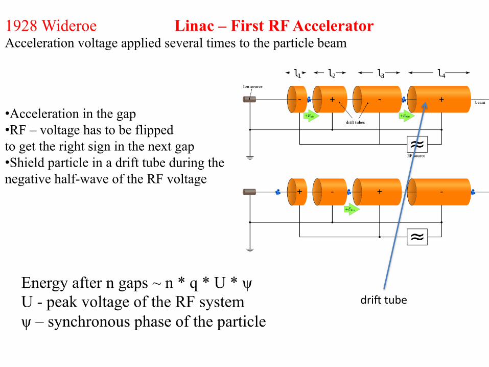
1928 Wideroe Linac – First RF Accelerator Acceleration voltage applied several times to the particle beam
• Acceleration in the gap • RF – voltage has to be flipped to get the right sign in the next gap • Shield particle in a drift tube during the negative half-wave of the RF voltage
Energy after n gaps ~ n * q * U * ψ U - peak voltage of the RF system ψ – synchronous phase of the particle
dri_tube
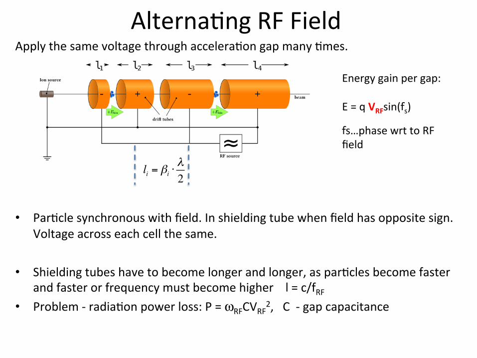
Alterna:ngRFFieldApplythesamevoltagethroughaccelera:ongapmany:mes.
• Par:clesynchronouswithfield.Inshieldingtubewhenfieldhasoppositesign.Voltageacrosseachcellthesame.
• Shieldingtubeshavetobecomelongerandlonger,aspar:clesbecomefasterandfasterorfrequencymustbecomehigherl=c/fRF
• Problem-radia:onpowerloss:P=ωRFCVRF2,C-gapcapacitance
li = βi ⋅λ2
Energygainpergap:E=qVRFsin(fs)fs…phasewrttoRFfield
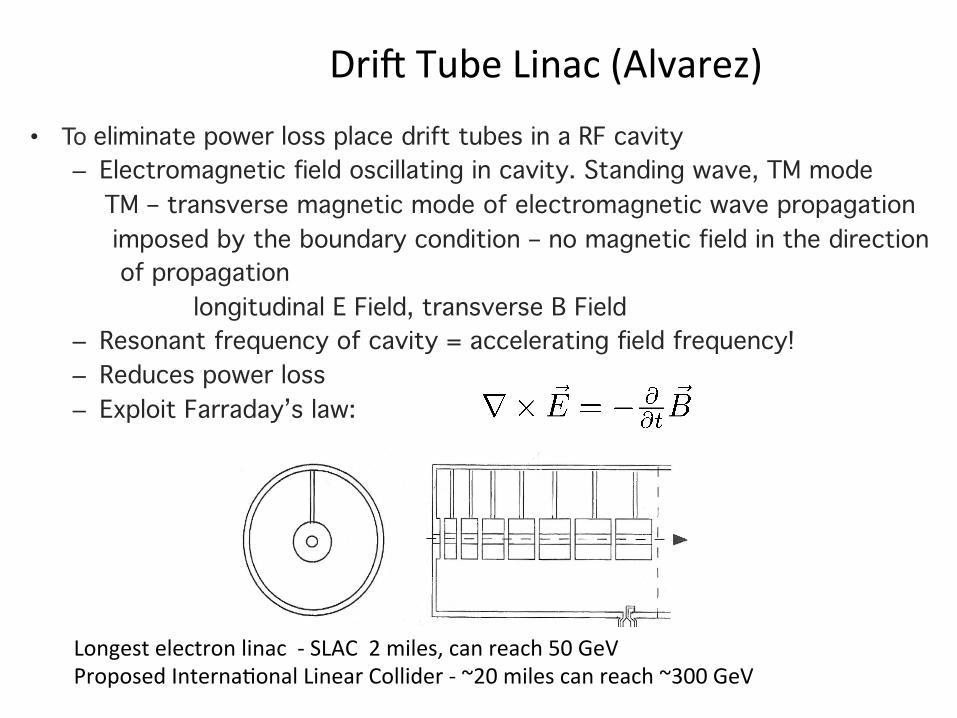
• To eliminate power loss place drift tubes in a RF cavity– Electromagnetic field oscillating in cavity. Standing wave, TM mode TM – transverse magnetic mode of electromagnetic wave propagation imposed by the boundary condition – no magnetic field in the direction of propagation
longitudinal E Field, transverse B Field– Resonant frequency of cavity = accelerating field frequency!– Reduces power loss– Exploit Farraday’s law:
Dri_TubeLinac(Alvarez)
Longestelectronlinac-SLAC2miles,canreach50GeVProposedInterna:onalLinearCollider-~20milescanreach~300GeV
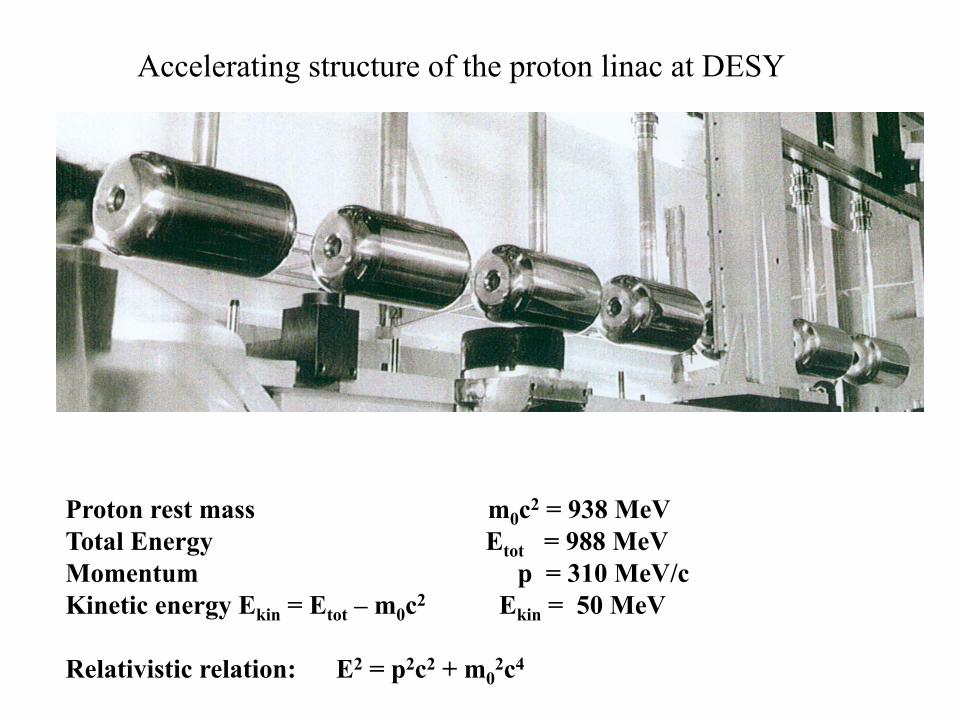
Accelerating structure of the proton linac at DESY
Proton rest mass m0c2 = 938 MeV Total Energy Etot = 988 MeV Momentum p = 310 MeV/c Kinetic energy Ekin = Etot – m0c2 Ekin = 50 MeV Relativistic relation: E2 = p2c2 + m0
2c4
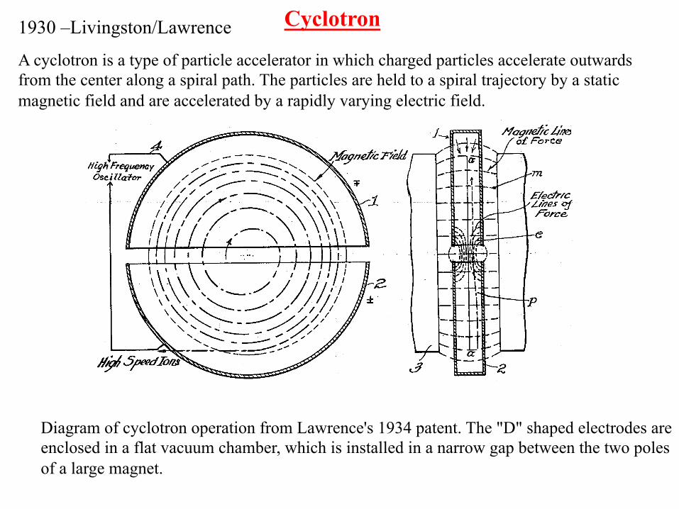
Cyclotron
A cyclotron is a type of particle accelerator in which charged particles accelerate outwards from the center along a spiral path. The particles are held to a spiral trajectory by a static magnetic field and are accelerated by a rapidly varying electric field.
1930 –Livingston/Lawrence
Diagram of cyclotron operation from Lawrence's 1934 patent. The "D" shaped electrodes are enclosed in a flat vacuum chamber, which is installed in a narrow gap between the two poles of a large magnet.
�
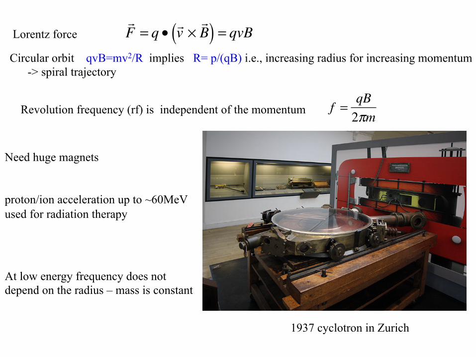
! F = q • ! v ×
! B ( ) = qvBLorentz force
Circular orbit qvB=mv2/R implies R= p/(qB) i.e., increasing radius for increasing momentum -> spiral trajectory
Revolution frequency (rf) is independent of the momentum
�
f =qB2πm
Need huge magnets proton/ion acceleration up to ~60MeV used for radiation therapy
1937 cyclotron in Zurich
At low energy frequency does not depend on the radius – mass is constant
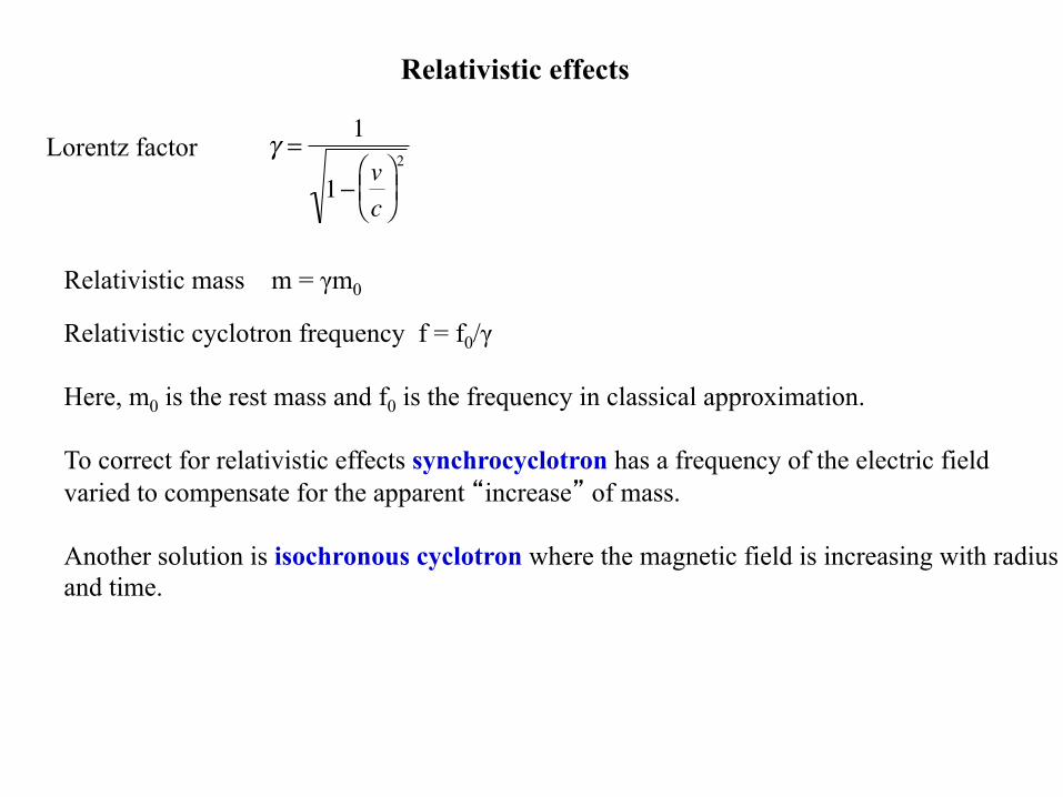
Relativistic effects
�
γ =1
1− vc⎛ ⎝ ⎜
⎞ ⎠ ⎟ 2Lorentz factor
Relativistic mass m = γm0 Relativistic cyclotron frequency f = f0/γ Here, m0 is the rest mass and f0 is the frequency in classical approximation. To correct for relativistic effects synchrocyclotron has a frequency of the electric field varied to compensate for the apparent “increase” of mass. Another solution is isochronous cyclotron where the magnetic field is increasing with radius and time.
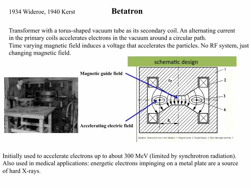
Betatron 1934 Wideroe, 1940 Kerst
Transformer with a torus-shaped vacuum tube as its secondary coil. An alternating current in the primary coils accelerates electrons in the vacuum around a circular path. Time varying magnetic field induces a voltage that accelerates the particles. No RF system, just changing magnetic field.
schema:cdesign
Magnetic guide field
Accelerating electric field
Initially used to accelerate electrons up to about 300 MeV (limited by synchrotron radiation). Also used in medical applications: energetic electrons impinging on a metal plate are a source of hard X-rays.
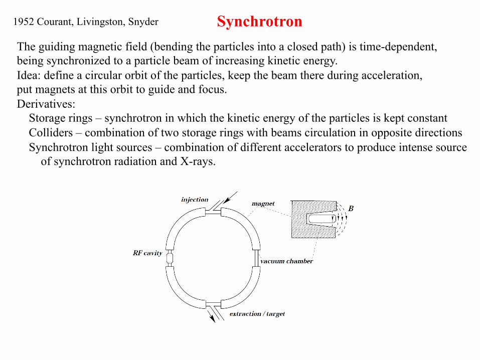
Synchrotron The guiding magnetic field (bending the particles into a closed path) is time-dependent, being synchronized to a particle beam of increasing kinetic energy. Idea: define a circular orbit of the particles, keep the beam there during acceleration, put magnets at this orbit to guide and focus. Derivatives: Storage rings – synchrotron in which the kinetic energy of the particles is kept constant Colliders – combination of two storage rings with beams circulation in opposite directions Synchrotron light sources – combination of different accelerators to produce intense source
of synchrotron radiation and X-rays.
1952 Courant, Livingston, Snyder
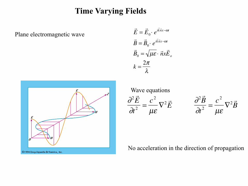
Time Varying Fields
Plane electromagnetic wave
�
! E =! E 0 ⋅ ei
! k ! n x−ωt
! B =! B 0 ⋅ ei
! k ! n x−ωt
! B 0 = µε ⋅ ! n x
! E o
k =2πλ
No acceleration in the direction of propagation
�
∂ 2! E
∂t 2=
c 2
µε∇2 ! E ∂ 2
! B
∂t 2=
c 2
µε∇2 ! B
Wave equations
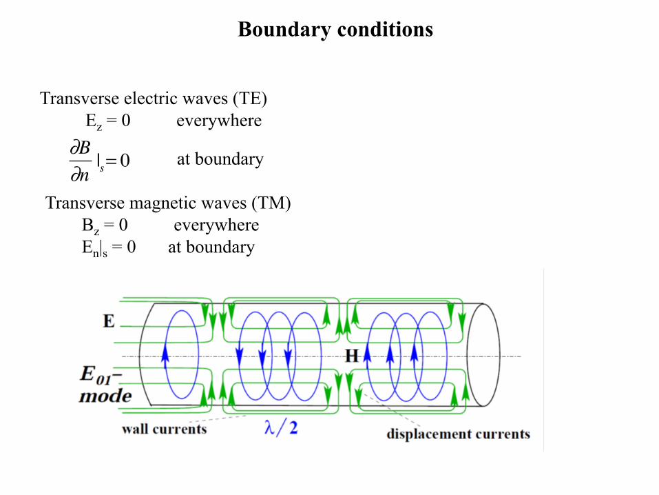
Boundary conditions
Transverse electric waves (TE) Ez = 0 everywhere
�
∂B∂n|s= 0 at boundary
Transverse magnetic waves (TM) Bz = 0 everywhere En|s = 0 at boundary


![a,b a arXiv:1804.00653v1 [physics.ins-det] 31 Mar 2018 · The double beta decay projects require as much as possible low, in ideal case zero, back-ground of a detector in a region](https://static.fdocument.org/doc/165x107/60b471cce5b9a47b380460af/ab-a-arxiv180400653v1-31-mar-2018-the-double-beta-decay-projects-require.jpg)