
Construction of a 1 MeV Electron Accelerator for High Precision Beta-Decay Studies
Accelerator Aspects of the Precision Mass
Measurement Experiments at the VEPP-4M
Collider with the KEDR Detector
S. A. Nikitin
for the VEPP-4 Team
BINP SB RAS
S. Nikitin Budker INP 2
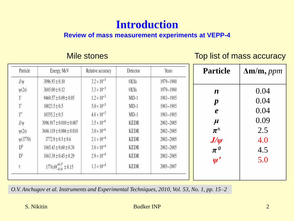
IntroductionReview of mass measurement experiments at VEPP-4
O.V. Anchugov et al. Instruments and Experimental Techniques, 2010, Vol. 53, No. 1, pp. 15–2
Particle Δm/m, ppm
n
p
e
μ
π±
J/ψ
π 0
ψ′
0.04
0.04
0.04
0.09
2.5
4.0
4.5
5.0
Mile stones Top list of mass accuracy
S. Nikitin Budker INP 3
Beam polarization measurement and beam energy
monitoring methods developed and applied
Problems on accuracy of energy calibration by spin
precession frequency studied at new level
Questions on optimal tuning of VEPP-4 systems and
operation modes for obtaining and application of
beam polarization in mass measurements set and
solved
What contributed
S. Nikitin Budker INP 4
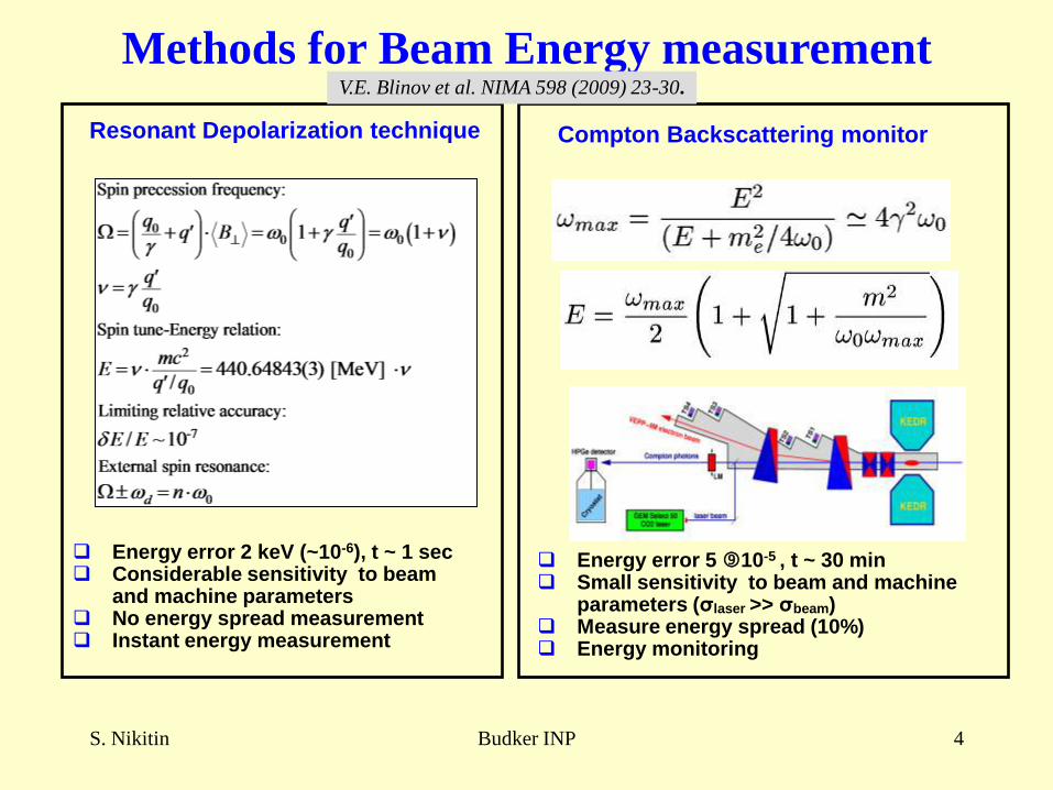
Compton Backscattering monitorResonant Depolarization technique
Energy error 5 10-5 , t ~ 30 min Small sensitivity to beam and machine
parameters (σlaser >> σbeam) Measure energy spread (10%) Energy monitoring
Energy error 2 keV (~10-6), t ~ 1 sec Considerable sensitivity to beam
and machine parameters No energy spread measurement Instant energy measurement
Methods for Beam Energy measurementV.E. Blinov et al. NIMA 598 (2009) 23-30.
S. Nikitin Budker INP 5
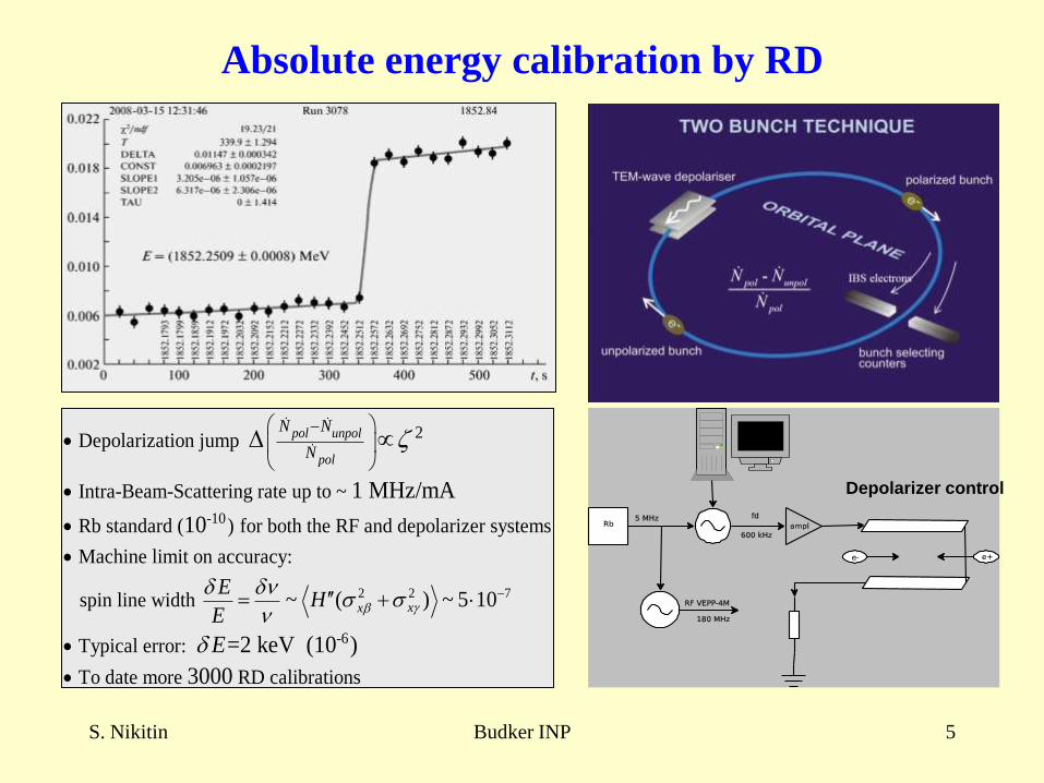
Absolute energy calibration by RD
Depolarizer control
-10
2 Depolarization jump
Intra-Beam-Scattering rate up to ~
Rb standard ( ) for both the RF and depolarizer systems
Machine limit on accuracy:
spin line w
1 MHz/mA
10
pol unpol
pol
N N
N
2 2 7
-6
idth
Typical error:
To date more RD calibrations
~ ( ) ~ 5 10
=2 keV (10 )
3000
xx
EH
E
E
S. Nikitin Budker INP 6
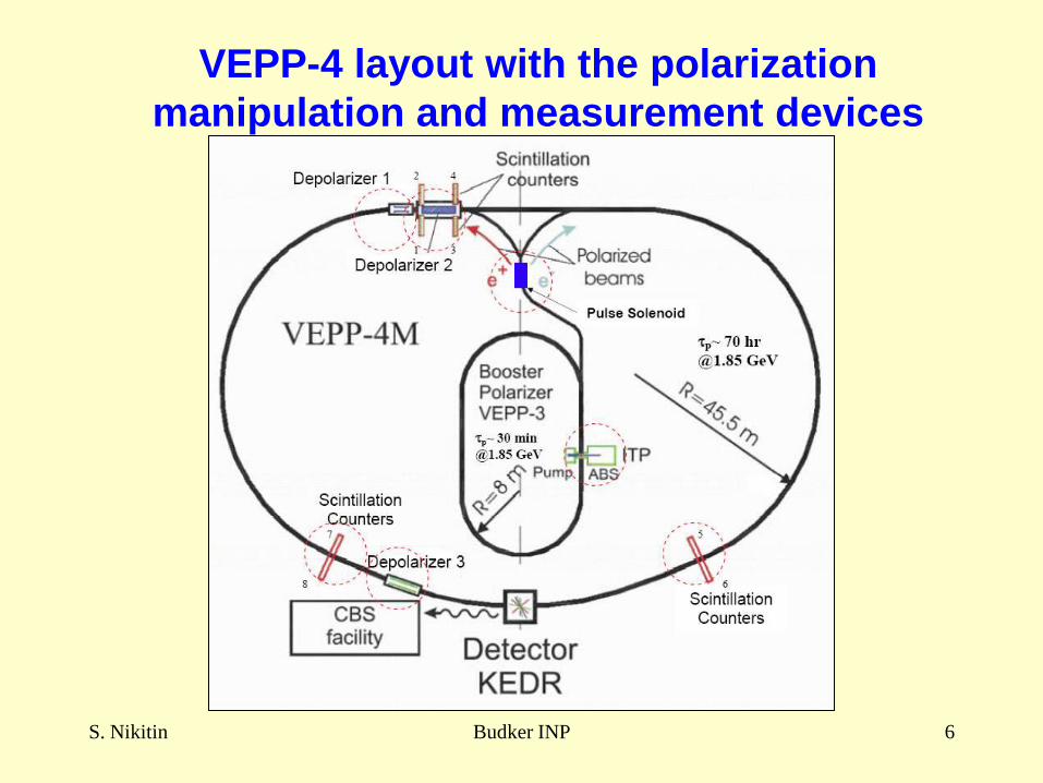
VEPP-4 layout with the polarization
manipulation and measurement devices
S. Nikitin Budker INP 7
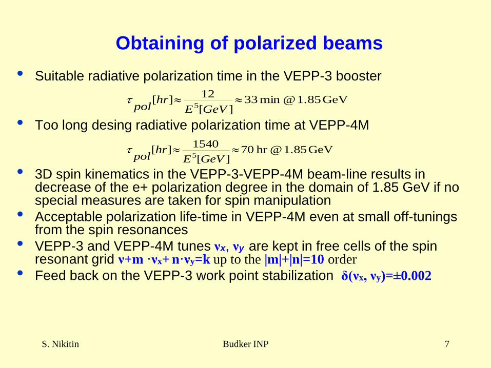
Obtaining of polarized beams
• Suitable radiative polarization time in the VEPP-3 booster
• Too long desing radiative polarization time at VEPP-4M
• 3D spin kinematics in the VEPP-3-VEPP-4M beam-line results in decrease of the e+ polarization degree in the domain of 1.85 GeV if no special measures are taken for spin manipulation
• Acceptable polarization life-time in VEPP-4M even at small off-tunings from the spin resonances
• VEPP-3 and VEPP-4M tunes νx, νy are kept in free cells of the spin resonant grid ν+m ·νx+ n·νy=k up to the |m|+|n|=10 order
• Feed back on the VEPP-3 work point stabilization δ(νx, νy)=±0.002
GeV 1.85 @hr 70][
1540][
5
GeVEhr
pol
GeV 1.85 @ min 33][
12][
5
GeVEhr
pol
S. Nikitin Budker INP 8
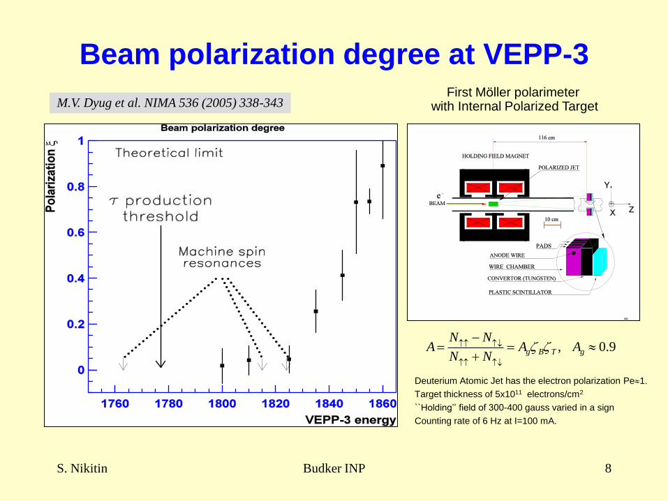
Beam polarization degree at VEPP-3
M.V. Dyug et al. NIMA 536 (2005) 338-343
, 0.9g B T g
N NA A A
N N
Deuterium Atomic Jet has the electron polarization Pe1.
Target thickness of 5x10¹¹ electrons/cm2
``Holding’’ field of 300-400 gauss varied in a sign
Counting rate of 6 Hz at I=100 mA.
First Möller polarimeter with Internal Polarized Target
S. Nikitin Budker INP 9
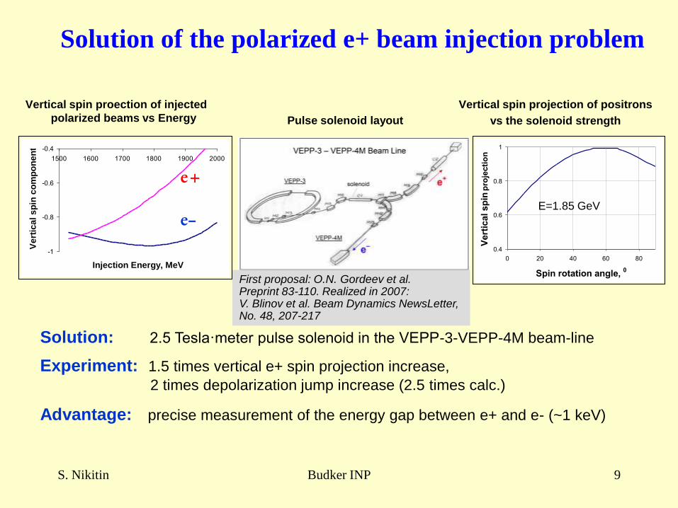
Solution of the polarized e+ beam injection problem
Vertical spin proection of injected
polarized beams vs Energy
Vertical spin projection of positrons
vs the solenoid strength
-1
-0.8
-0.6
-0.4
1500 1600 1700 1800 1900 2000
Injection Energy, MeV
Ve
rtic
al
sp
in c
om
po
ne
nt
e–
e+
0.4
0.6
0.8
1
0 20 40 60 80
Spin rotation angle, 0
Vert
ical sp
in p
roje
cti
on
Solution: 2.5 Tesla·meter pulse solenoid in the VEPP-3-VEPP-4M beam-line
Experiment: 1.5 times vertical e+ spin projection increase,
2 times depolarization jump increase (2.5 times calc.)
Advantage: precise measurement of the energy gap between e+ and e- (~1 keV)
First proposal: O.N. Gordeev et al. Preprint 83-110. Realized in 2007: V. Blinov et al. Beam Dynamics NewsLetter, No. 48, 207-217
Pulse solenoid layout
E=1.85 GeV
S. Nikitin Budker INP 10
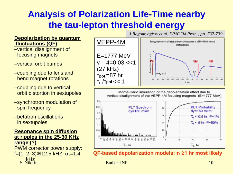
Analysis of Polarization Life-Time nearby
the tau-lepton threshold energy
VEPP-4M
E=1777 MeV
ν – 4=0.03 <<1(27 kHz)τpol =87 hrτr /τpol << 1
Depolarization by quantum fluctuations (QF)–vertical disalignment of
focusing magnets
–vertical orbit bumps
–coupling due to lens and bend magnet rotations
–coupling due to vertical orbit distortion in sextupoles
–synchrotron modulation of spin frequency
–betatron oscillations in sextupoles
Resonance spin diffusion at ripples in the 25-30 KHzrange (?)PWM corrector power supply:f=(1, 2, 3)12.5 kHZ, σν=1.4
kHz
QF-based depolarization models: τr ≥1 hr most likely
A.Bogomyagkov et al. EPAC’04 Proc. , pp. 737-739
S. Nikitin Budker INP 11
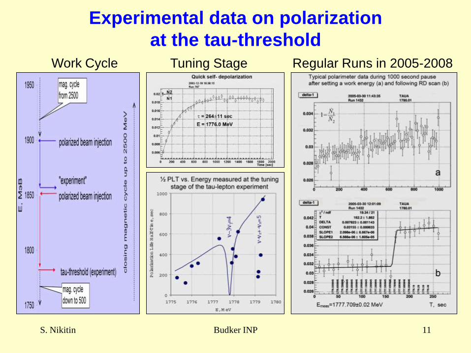
Experimental data on polarization
at the tau-threshold
Work Cycle Tuning Stage Regular Runs in 2005-2008
S. Nikitin Budker INP 12
Questions on Accuracy
Accuracy of instant absolute energy calibration
Modulation spin resonances
Spin tune shift not conserving the “spin tune - energy” ratio
Effect of orbit corrections on energy
Central mass energy determination
Energy and energy spread stability
S. Nikitin Budker INP 13
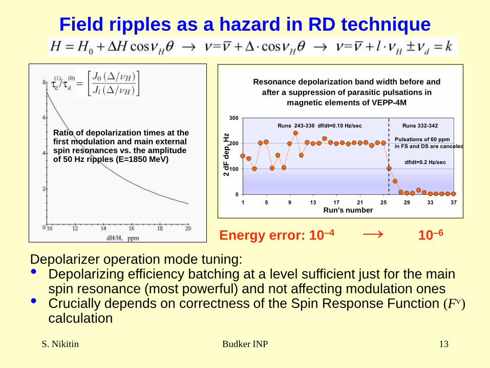
Field ripples as a hazard in RD technique
Resonance depolarization band width before and
after a suppression of parasitic pulsations in
magnetic elements of VEPP-4M
0
100
200
300
1 5 9 13 17 21 25 29 33 37
Run's number
2 d
F d
ep
, H
z
Runs 243-330 df/dt=0.10 Hz/sec Runs 332-342
Pulsations of 60 ppm
in FS and DS are canceled
df/dt=0.2 Hz/sec
Ratio of depolarization times at the first modulation and main externalspin resonances vs. the amplitude of 50 Hz ripples (E=1850 MeV)
Depolarizer operation mode tuning:• Depolarizing efficiency batching at a level sufficient just for the main
spin resonance (most powerful) and not affecting modulation ones• Crucially depends on correctness of the Spin Response Function (F)
calculation
Energy error: 10–4 → 10–6
S. Nikitin Budker INP 14
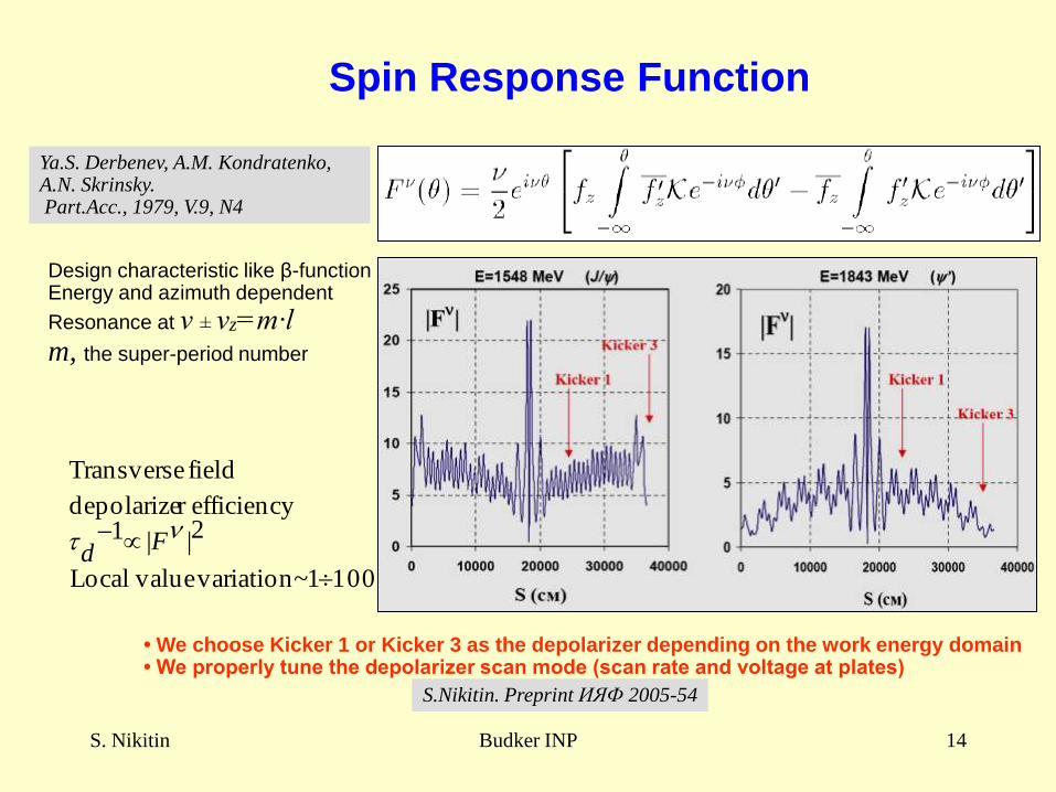
Spin Response Function
1001~ variation valueLocal
2|| 1efficiencyr depolarize
field Transverse
Fd
Ya.S. Derbenev, A.M. Kondratenko, A.N. Skrinsky.Part.Acc., 1979, V.9, N4
• We choose Kicker 1 or Kicker 3 as the depolarizer depending on the work energy domain• We properly tune the depolarizer scan mode (scan rate and voltage at plates)
Design characteristic like β-functionEnergy and azimuth dependent
Resonance at ν ± νz=m·lm, the super-period number
S.Nikitin. Preprint ИЯФ 2005-54
S. Nikitin Budker INP 15
FD
Z0
i+1
i
DH H
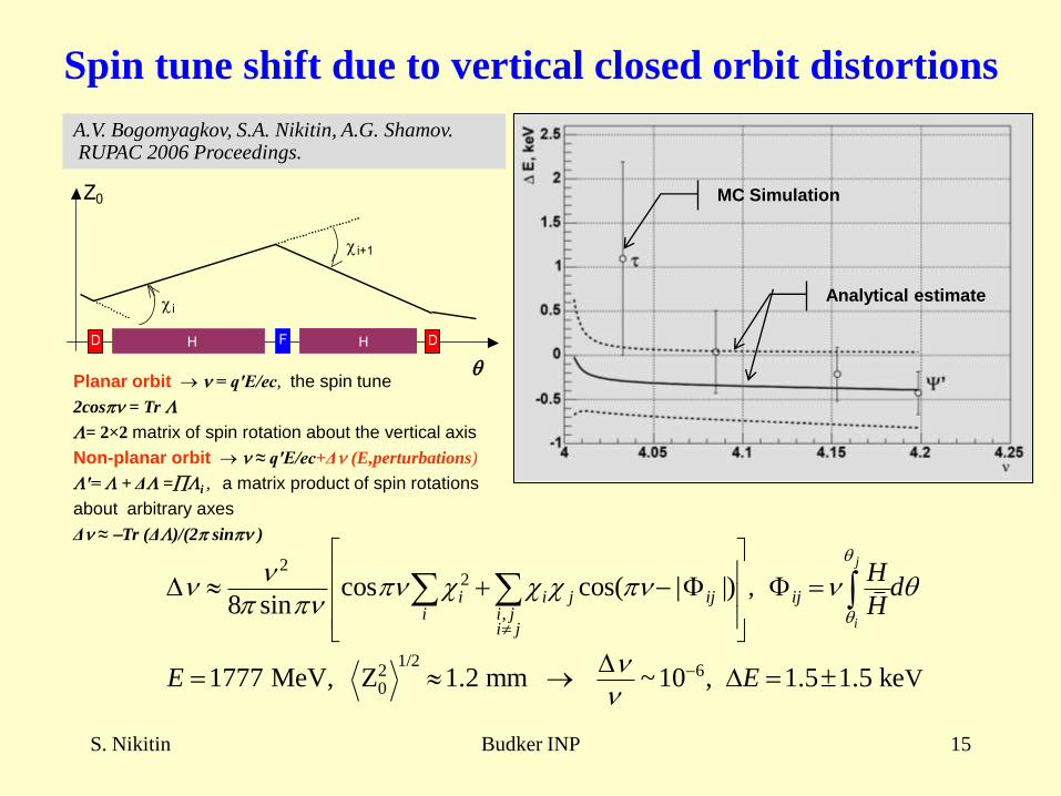
Spin tune shift due to vertical closed orbit distortions
MC Simulation
Analytical estimate
A.V. Bogomyagkov, S.A. Nikitin, A.G. Shamov.RUPAC 2006 Proceedings.
22
,
1/22 60
,
V
cos cos( | |)8 sin
1777 MeV, Z 1.2 mm ~10 , 1.5 1.5 ke
j
i
i i j ij iji i j
i j
Hd
H
E E
Planar orbit = q′E/ec, the spin tune
2cos = Tr L
L= 2×2 matrix of spin rotation about the vertical axis
Non-planar orbit ≈ q′E/ec+Δ (E,perturbations)
L′= L + ΔL =Li , a matrix product of spin rotations
about arbitrary axes
Δ ≈ Tr (ΔL)/(2 sin )
S. Nikitin Budker INP 16
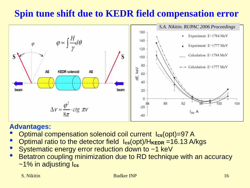
Spin tune shift due to KEDR field compensation error
Advantages:• Optimal compensation solenoid coil current Ics(opt)=97 A• Optimal ratio to the detector field Ics(opt)/HKEDR =16.13 A/kgs• Systematic energy error reduction down to ~1 keV• Betatron coupling minimization due to RD technique with an accuracy
~1% in adjusting Ics
S.A. Nikitin. RUPAC 2006 Proceedings
S. Nikitin Budker INP 17
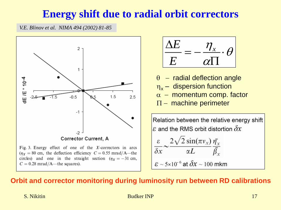
Energy shift due to radial orbit correctors
xE
E
radial deflection angle
x – dispersion function
momentum comp. factor
machine perimeter
V.E. Blinov et al. NIMA 494 (2002) 81-85
Orbit and corrector monitoring during luminosity run between RD calibrations
S. Nikitin Budker INP 18
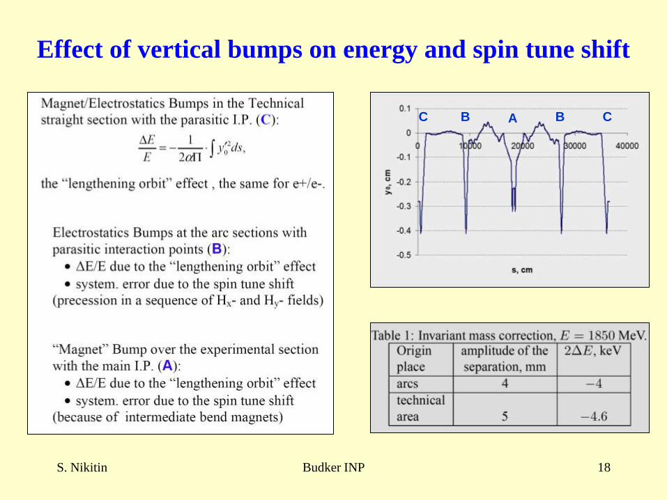
Effect of vertical bumps on energy and spin tune shift
C CAB B
S. Nikitin Budker INP 19
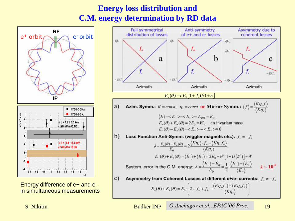
Energy loss distribution and
C.M. energy determination by RD data
e+ orbit e- orbitRF
0( ) 1 ( )E E f
IP
Energy difference of e+ and e-in simultaneous measurements
O.Anchugov et al., EPAC’06 Proc.
S. Nikitin Budker INP 20
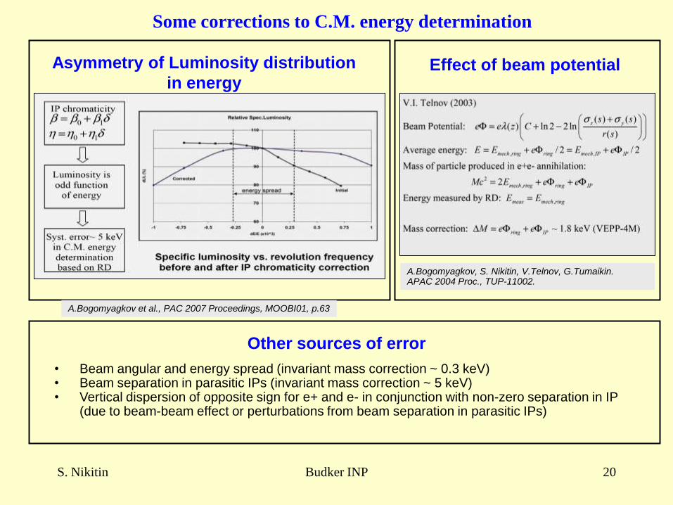
Asymmetry of Luminosity distribution
in energyEffect of beam potential
A.Bogomyagkov, S. Nikitin, V.Telnov, G.Tumaikin.APAC 2004 Proc., TUP-11002.
• Beam angular and energy spread (invariant mass correction ~ 0.3 keV)• Beam separation in parasitic IPs (invariant mass correction ~ 5 keV)• Vertical dispersion of opposite sign for e+ and e- in conjunction with non-zero separation in IP
(due to beam-beam effect or perturbations from beam separation in parasitic IPs)
A.Bogomyagkov et al., PAC 2007 Proceedings, MOOBI01, p.63
Some corrections to C.M. energy determination
Other sources of error
S. Nikitin Budker INP 21
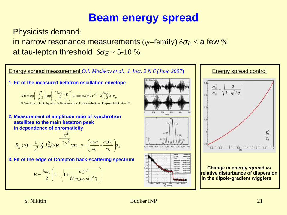
Beam energy spread
87.76 ÈßÔ Preprint entsev. E.Perevednov,V.Korchuga v,G.Kulipano v,N.Vinokuro
221 ,)cos(1
2
exp22
2exp)(
yb
ats
s
EE
ttA
Change in energy spread vs relative disturbance of dispersion in the dipole-gradient wigglers
Physicists demand:
in narrow resonance measurements (ψ–family) δσE < a few %
at tau-lepton threshold δσE ~ 5-10 %
Energy spread measurement O.I. Meshkov et al., J. Inst. 2 N 6 (June 2007)
1. Fit of the measured betatron oscillation envelope
Energy spread control
2. Measurement of amplitude ratio of synchrotron
satellites to the main betatron peak
in dependence of chromaticity
E
s
y
s
Cyxdx
y
x
exmJy
ym
R
0
,0
22
2
)(22
1)(
2
2
0
2
42
sin11
2
m
em cmE
3. Fit of the edge of Compton back-scattering spectrum
S. Nikitin Budker INP 22
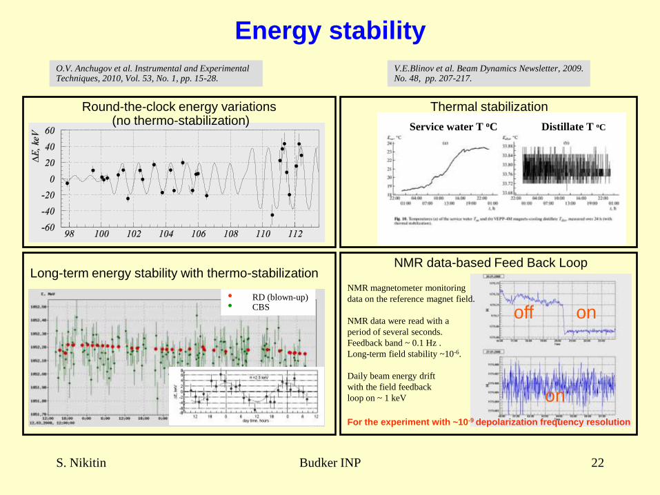
Energy stability
NMR magnetometer monitoring
data on the reference magnet field.
NMR data were read with a
period of several seconds.
Feedback band ~ 0.1 Hz .
Long-term field stability ~10-6.
Daily beam energy drift
with the field feedback
loop on ~ 1 keV
Round-the-clock energy variations (no thermo-stabilization)
Long-term energy stability with thermo-stabilization
Thermal stabilization
NMR data-based Feed Back Loop
off on
on
O.V. Anchugov et al. Instrumental and Experimental Techniques, 2010, Vol. 53, No. 1, pp. 15-28.
V.E.Blinov et al. Beam Dynamics Newsletter, 2009. No. 48, pp. 207-217.
Service water T oC Distillate T oC
• RD (blown-up)• CBS
For the experiment with ~10-9 depolarization frequency resolution
S. Nikitin Budker INP 23
Acknowledgements
Thanks to V.Smaluk, S.Karnaev and
V.Kiselev for help in material preparation.
S. Nikitin Budker INP 24
Thank you for attention!