AC SERVO DRIVES Σ-S SERIES - YASKAWA Asean · AC SERVO DRIVES SERIES Easy! ... A magnetic encoder...
16
AC SERVO DRIVES SERIES Easy! Compact! and Low Price! SGPSS SERVOPACKs SGMSL Servomotors Certified for ISO9001 and ISO14001 JQA-EM0202 JQA-0422
Transcript of AC SERVO DRIVES Σ-S SERIES - YASKAWA Asean · AC SERVO DRIVES SERIES Easy! ... A magnetic encoder...
AC SERVO DRIVESSERIES
Easy! Compact! and Low Price!
SGPSS SERVOPACKs
SGMSL Servomotors
Certified for
ISO9001 and
ISO14001
JQA-EM0202JQA-0422

SERVOPACK with Contact Commands (Program Table Method)
-Series Servos Easily Handle Applicationsbeyond Those of Conventional Servo Drives!Although compact and low-priced, the -Series Servos also provide real servo capabilities.They provide the capabilities of positioning servos that are ideal for converting pneumaticequipment to Servomotors.If you thought a servo system could not handle your application,think again and try the Series.
SGMSL-A3
SGMSL-A5
30 W
50 W
Rated Output
85 mm
92 mm
Model
25 mm
40 mm
180g350g
Compact and Lightweight
Low Prices and Greater Savings in Energy and Costs
Easy Operation and Increased Productivity
The PCB format (80 mm × 123 mm) provides a high degree of
installation freedom and helps you downsize equipment.
SGPSS SERVOPACKs
SGMSL Servomotors
and tryrr the Series.SGPSS SERVOPACKs
SGMSL Servomotors
Models are available with 25 mm × 25 mm or 40 mm × 40 mm flanges to
help you downsize equipment.
DC power supply input.
Two types of reference interfaces:
Contact commands (program table method)
and pulse train references.
Rated output of 30 W or 50 W.
Rated Motor Speed/Maximum Motor Speed:
3,000 min-1/6,000 min-1 (30 W) or
3,000 min-1/3,000,min-1 (50 W)
Total Length Shaft DiameterSquare Flange
DimensionsMass
5 dia.0−0.013
8 dia.0−0.013
A magnetic encoder is used and general-purpose AC Servo Drive performances and functions have been
reduced to only those necessary to replace pneumatic equipment to achieve an amazingly low price.
And AC Servo Drive technology has been put to work to greatly reduce energy usage in comparison with
pneumatic equipment or stepping motors to cut equipment running costs.
With the rated motor speed of 3,000 min-1 and acceleration/deceleration control, you can reduce takt time.
You can use Yaskawa’s SigmaWin+ Engineering Tool (free of charge) from trial operation to servo tuning
and programming to easily complete setup.
You can use flexible drive patterns to eliminate the need for changeovers for different workpieces.
Positioning functions are built in, eliminating the need for motion programming in the host controller.
Just enter numeric values into the tables provided by SigmaWin+ to easily program operation.
Compliance with EC Directives
2
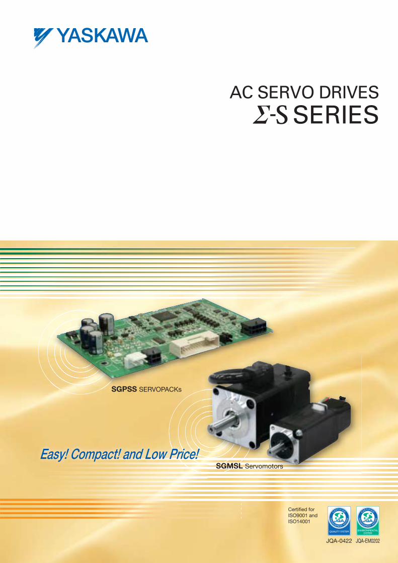
SGPSS 3R1̶ C H1 A
Pneumatic Actuator
Electric Actuator
Motor
Compressor
Air purifierAir-pressureauxiliary device
Directionalcontrol device
Pneumaticactuator
Energy conversion loss: High Energy conversion loss: High
Electric power conversion loss: Low
Pressure transmission loss: High
Replacing Pneumatic Equipment with the Series
AC Servomotor
Applications for Electric Chucks
Replacing Pneumatic Equipment with Servo Drives
PotentialApplication
1
PotentialApplication
2
SGMSL A3 C K A A 1̶
Maximumapplicablemotor capacity 3R1: 50 W
Voltage: 24 VDC
Designrevisionorder
Designrevisionorder
Voltage: 24 VDC
Rated outputA3: 30 WA5: 50 W
Shaft end2: Straight, A: Straight with flat seat
No options
InterfaceH1: Contact commands, rotaryP1: Pulse train references, rotary
-SeriesSERVOPACK
-SeriesServomotor
Encoder specifications:
10-bit magnetic incremental encoder
Low heat generation and low-level operating noise.
Impressive reference tracking capability to reduce takt time.
Multi-point positioning for easy application to different types
of workpieces.
Torque limit settings to adjust chucking holding power.
The need for pneumatic equipment is eliminated to save space and costs.
Low heat generation and low-level operating noise.
High-speed rotation and high torque characteristics improve work
efficiency and quality.
Impressive reference tracking capability and acceleration/
deceleration control to reduce takt time.
Convenient functions to replace pneumatic equipment
enable easy programming.
Low energy conversion loss to reduce running costs.Electricity
Electric Actuator
AC Servomotor
d costs.
Elect iccit
Model Designations
SERVOPACKs Servomotors
Compliance with EC Directives
SERVOPACKs: SGPSS-3R1C Servomotors: SGMSL
European Directive
EMC Directive
2004/108/EC
Low Voltage Directive
2006/95/EC
EN 55011 group1, class A
EN 61000-6-2
EN 61000-6-4, EN 61800-3
EN 61800-5-1
Harmonized Standards European Directive
EMC Directive
2004/108/EC
Low Voltage Directive
2006/95/EC
EN 55011 group1, class A
EN 61000-6-2
EN 61000-6-4, EN 61800-3
EN 60034-1
EN 60034-5
Harmonized Standards
3
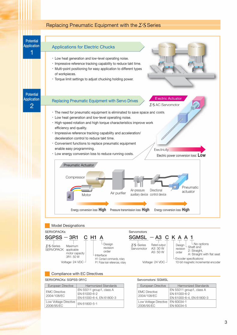
Control Performance
Program Table Operation (for SERVOPACKs with Contact Commands only)
By using the Series in equipment, you can use the superior performance of an AC Servo Drive to increase equipment value.
Pressing Operation
Zone Outputs
Multi-point Positioning
Acceleration/Deceleration Control
PGMSTEP
POS
SPD
ACC
DEC
TLIMT
PLIMT
CLLV
PSPD
INPOS
AREA1
AREA2
EVENT
NEXT
Program step
Target position
Positioning speed specification
Acceleration specification
Deceleration specification
Torque limit specification for positioning
Torque limit specification for pressing operation
Torque threshold (INPOS output level during pressing operation)
Movement speed during pressing operation
Positioning completed width
Reverse area boundary position
Forward area boundary position
End criteria
Program step to execute next (PGMSTEP)
You can set (program) positioning operation patterns in tables in advance and then use input signals from the host controller to specify the
operation patterns to achieve automatic operation. Two types of programmed operations are provided: positioning and pressing operation.
After a movement to the target position with positioning operation,actuator pressing operation is performed at the specified torque.
Example of Positioning Operation
Example of Pressing Operation
Travel distance:
100,000 reference units
Origin Position
100,000
Speed[reference units/s]
Speed PGMSTEP 1 PGMSTEP 1PGMSTEP 2
10,000
Time
Travel distance:
5,000 reference units
Actual traveldistance
SPD Movement at 100,000 reference units/s
Movementwith PSPD
Pressing
operation with
PTLIMT
Pressing operationstating position
Pressing OperationPositioning Operation
PGMSTEP
3
POS
A+100000
SPD
100000
ACC
:
DEC
:
TLIMT
:
PTLIMT
50
CLLV
40
PSPD
10000
INPOS
5000
AREA1
0
AREA2
0
EVENT
IT0
NEXT
END
PGMSTEP
1
2
POS
I+300000
I-300000
SPD
15000
30000
ACC
:
:
DEC
:
:
TLIMT
:
:
PTLIMT
0
0
CLLV
:
:
PSPD
:
:
INPOS
10
10
AREA1
0
0
AREA2
0
0
EVENT
IT2000
IT2000
NEXT
2
1
Time
Waitingtime:2 s
Waitingtime:2 s
Waitingtime:2 s
The workpiece can be pressed or held in place at any force (torque). Workpiece damage and omissions are reduced
because even fragile workpieces can be held or workpieces
can be held securely, which increases work quality.
You can perform positioning to different target positions. You can
set the target positions required for the workpieces to eliminate the
need for machine changeover operations to match workpiece size.
This allows you to easily handle different types of workpieces.
Workpieces are detected in realtime when they reach a specified zone
and a digital signal is output. For example, with pneumatic equipment,
there is no way to tell when the workpiece has reached the target zone,
and waiting time becomes necessary to allow for time differences that
result from changes in load mass and friction. You can use the zone
outputs of the Series to time starting the next operation, eliminating
waiting time and increasing manufacturing throughput.
Acceleration at startup and deceleration when stopping can
be controlled to the required values. With pneumatic
equipment, rapid changes in speed when starting and
stopping can have adverse effects on workpieces, which
can fly out of control. By using the acceleration/deceleration
control of the Series, impact is reduced when starting
and stopping to prevent that type of problem.
Program Table
Program Table
Operation Pattern
Operation Pattern Program Settings
4
Rotary Servomotors
SGMSL
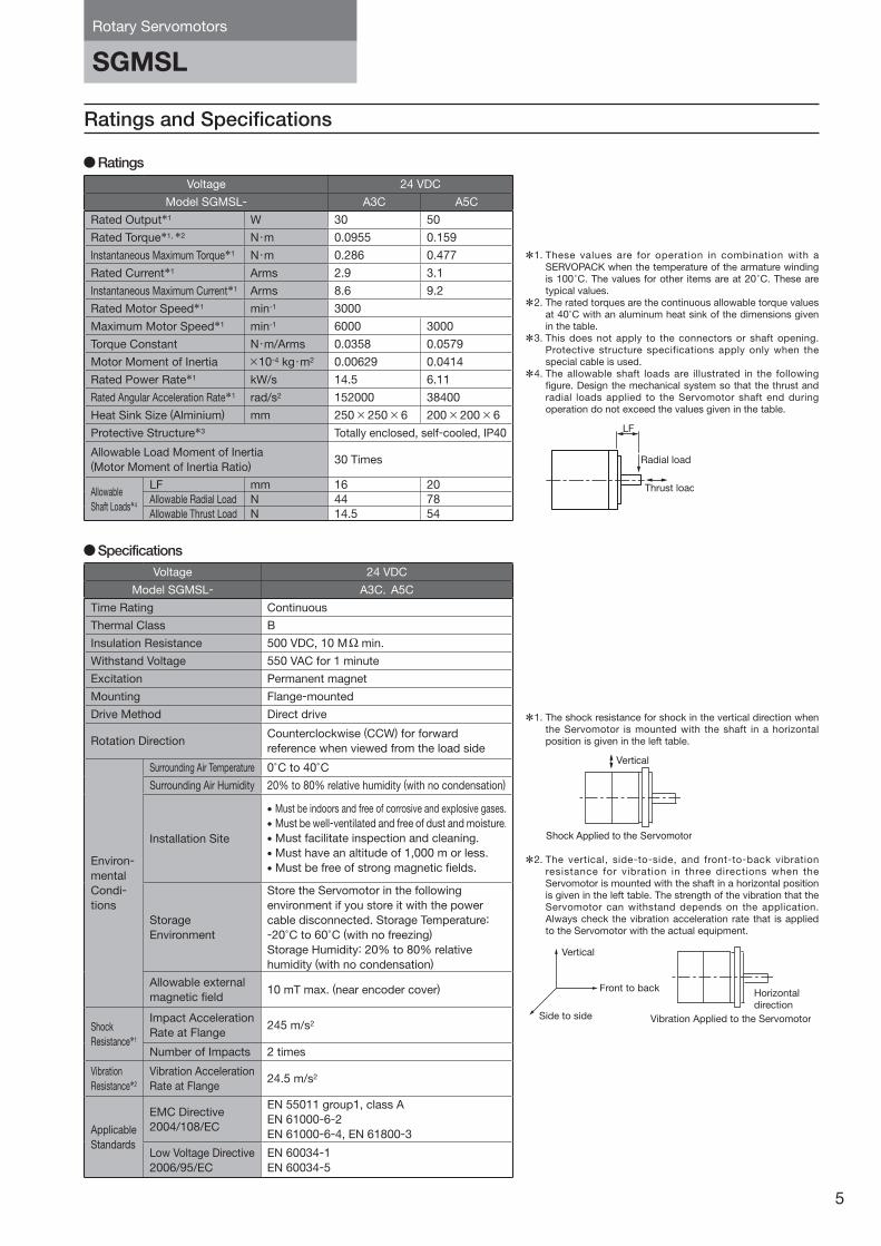
Ratings and Specifications
Ratings
SpecificationsVoltage 24 VDC
Model SGMSL- A3C,A5C
Time Rating Continuous
Thermal Class B
Insulation Resistance 500 VDC, 10 MΩ min.
Withstand Voltage 550 VAC for 1 minute
Excitation Permanent magnet
Mounting Flange-mounted
Drive Method Direct drive
Rotation DirectionCounterclockwise (CCW) for forward
reference when viewed from the load side
Environ-
mental
Condi-
tions
Surrounding Air Temperature 0°C to 40°CSurrounding Air Humidity 20% to 80% relative humidity (with no condensation)
Installation Site
• Must be indoors and free of corrosive and explosive gases.
• Must be well-ventilated and free of dust and moisture.• Must facilitate inspection and cleaning.
• Must have an altitude of 1,000 m or less.
• Must be free of strong magnetic fields.
Storage
Environment
Store the Servomotor in the following
environment if you store it with the power
cable disconnected. Storage Temperature:
-20°C to 60°C (with no freezing)
Storage Humidity: 20% to 80% relative
humidity (with no condensation)
Allowable external
magnetic field10 mT max. (near encoder cover)
Shock
Resistance*1
Impact Acceleration
Rate at Flange245 m/s2
Number of Impacts 2 times
Vibration
Resistance*2
Vibration Acceleration
Rate at Flange24.5 m/s2
Applicable
Standards
EMC Directive
2004/108/EC
EN 55011 group1, class A
EN 61000-6-2
EN 61000-6-4, EN 61800-3
Low Voltage Directive
2006/95/EC
EN 60034-1
EN 60034-5
Voltage 24 VDC
Model SGMSL- A3C A5C
Rated Output*1 W 30 50
Rated Torque*1, *2 N・m 0.0955 0.159
Instantaneous Maximum Torque*1 N・m 0.286 0.477
Rated Current*1 Arms 2.9 3.1
Instantaneous Maximum Current*1 Arms 8.6 9.2
Rated Motor Speed*1 min-1 3000
Maximum Motor Speed*1 min-1 6000 3000
Torque Constant N・m/Arms 0.0358 0.0579
Motor Moment of Inertia ×10-4 kg・m2 0.00629 0.0414
Rated Power Rate*1 kW/s 14.5 6.11
Rated Angular Acceleration Rate*1 rad/s2 152000 38400
Heat Sink Size (Alminium) mm 250 × 250 × 6 200 × 200 × 6
Protective Structure*3 Totally enclosed, self-cooled, IP40
Allowable Load Moment of Inertia(Motor Moment of Inertia Ratio)
30 Times
Allowable
Shaft Loads*4
LF mm 16 20
Allowable Radial Load N 44 78
Allowable Thrust Load N 14.5 54
*1. These values are for operation in combination with a SERVOPACK when the temperature of the armature winding is 100°C. The values for other items are at 20°C. These are typical values.
*2. The rated torques are the continuous allowable torque values at 40°C with an aluminum heat sink of the dimensions given in the table.
*3. This does not apply to the connectors or shaft opening. Protective structure specifications apply only when the special cable is used.
*4. The allowable shaft loads are illustrated in the following figure. Design the mechanical system so that the thrust and radial loads applied to the Servomotor shaft end during operation do not exceed the values given in the table.
Radial load
Thrust load
LF
*1. The shock resistance for shock in the vertical direction when the Servomotor is mounted with the shaft in a horizontal position is given in the left table.
*2. The vertical, side-to-side, and front-to-back vibration resistance for vibration in three directions when the Servomotor is mounted with the shaft in a horizontal position is given in the left table. The strength of the vibration that the Servomotor can withstand depends on the application. Always check the vibration acceleration rate that is applied to the Servomotor with the actual equipment.
Vertical
Shock Applied to the Servomotor
Horizontaldirection
Vibration Applied to the ServomotorSide to side
Vertical
Front to back
5
P05-15_KAEPS80000140B_1_0.indd 5 15.3.3 9:03:12 AM
SGMSL
Rotary Servomotors
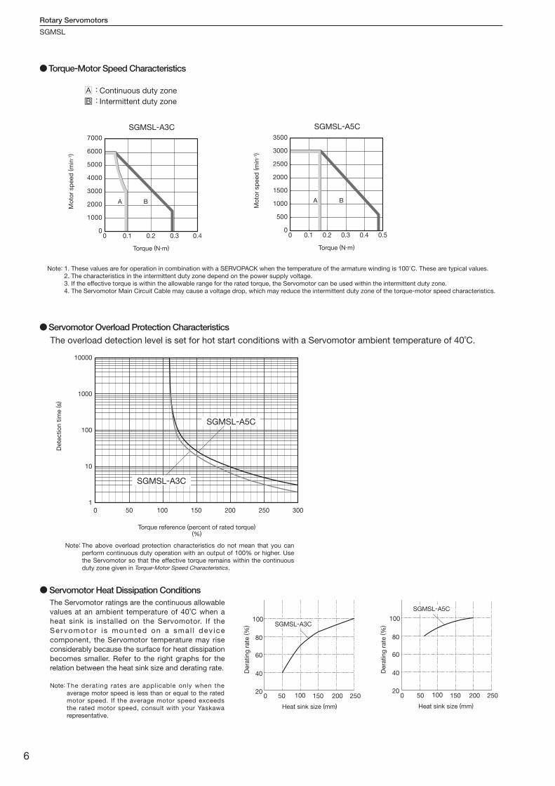
Torque-Motor Speed Characteristics
A B
A : Continuous duty zone
B : Intermittent duty zone
0
1000
2000
3000
4000
5000
6000
7000
0 0.40.30.20.1
SGMSL-A3C
Mo
tor
sp
eed
(m
in-1
)
Torque (N m)
A B
3500
3000
2500
2000
1500
1000
500
00 0.1 0.2 0.3 0.4 0.5
SGMSL-A5C
Mo
tor
sp
eed
(m
in-1
)
Torque (N m)
1. These values are for operation in combination with a SERVOPACK when the temperature of the armature winding is 100°C. These are typical values.2. The characteristics in the intermittent duty zone depend on the power supply voltage.3. If the effective torque is within the allowable range for the rated torque, the Servomotor can be used within the intermittent duty zone.4. The Servomotor Main Circuit Cable may cause a voltage drop, which may reduce the intermittent duty zone of the torque-motor speed characteristics.
Note:
The above overload protection characteristics do not mean that you can perform continuous duty operation with an output of 100% or higher. Use the Servomotor so that the effective torque remains within the continuous duty zone given in Torque-Motor Speed Characteristics.
Note:
The derating rates are applicable only when the average motor speed is less than or equal to the rated motor speed. If the average motor speed exceeds the rated motor speed, consult with your Yaskawa representative.
Note:
Servomotor Overload Protection CharacteristicsThe overload detection level is set for hot start conditions with a Servomotor ambient temperature of 40˚C.
● Servomotor Heat Dissipation ConditionsThe Servomotor ratings are the continuous allowable
values at an ambient temperature of 40˚C when a
heat sink is installed on the Servomotor. If the
Servomotor i s mounted on a smal l dev ice
component, the Servomotor temperature may rise
considerably because the surface for heat dissipation
becomes smaller. Refer to the right graphs for the
relation between the heat sink size and derating rate.
100
80
60
40
20150 250200100500
Heat sink size (mm)
SGMSL-A5C
150 250200100500
Heat sink size (mm)
100
80
60
40
20
Dera
tin
g r
ate
(%
)
Dera
tin
g r
ate
(%
)SGMSL-A3C
Torque reference (percent of rated torque)(%)
Dete
ctio
n t
ime (s)
10000
1000
100
10
1
0 50 100 150 200 250 300
SGMSL-A3C
SGMSL-A5C
6
P05-15_KAEPS80000140B_1_0.indd 6 15.3.3 9:03:13 AM
Rotary Servomotors
SGMSL
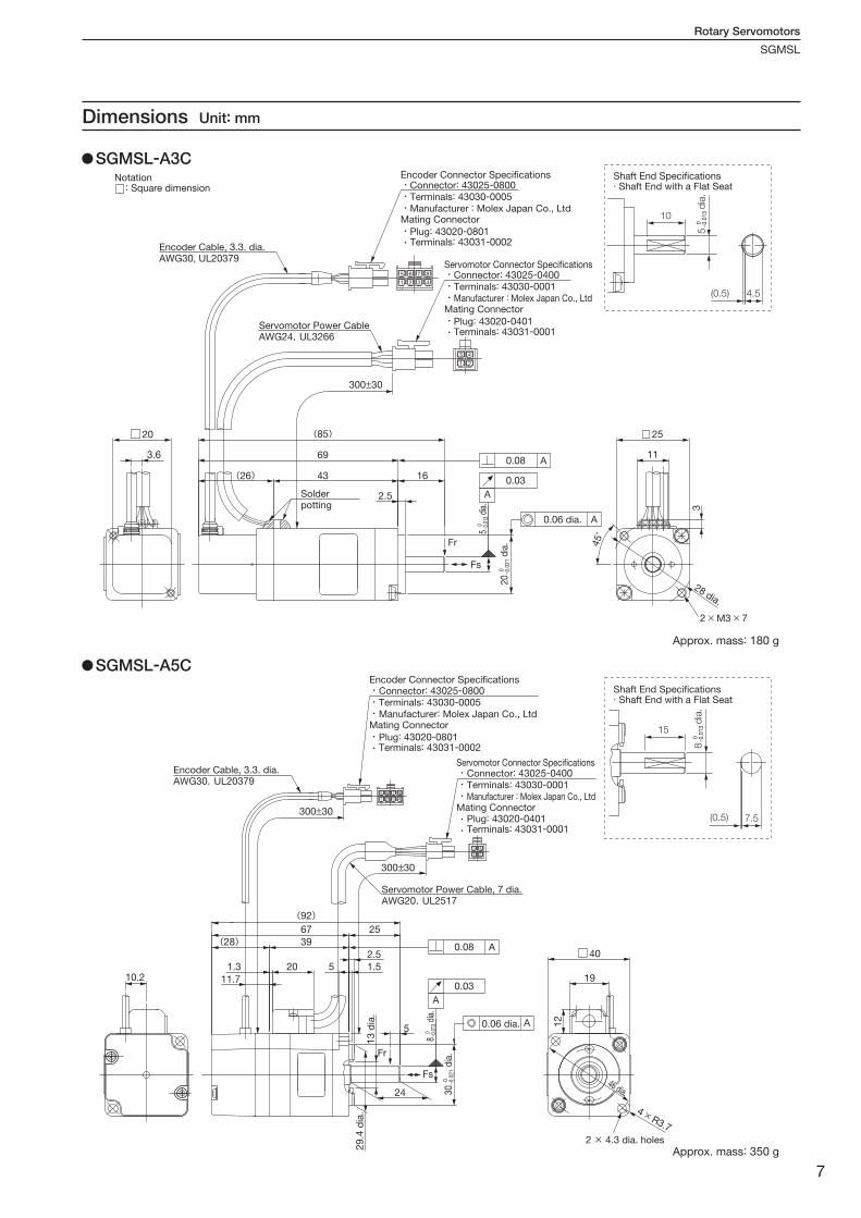
Dimensions Unit: mm
AWG30, UL20379
Solderpotting
Servomotor Power CableAWG24,UL3266
Connector: 43025-0800Terminals: 43030-0005Manufacturer : Molex Japan Co., Ltd
Encoder Connector Specifications
Mating Connector
Plug: 43020-0801Terminals: 43031-0002
(85)
300±30
69
(26) 43 16
2.5
Fr
Fs
0.08
0.03
A
A
A
20 25
3.6 11
3
45゚
2 × M3 × 7
Connector: 43025-0400Terminals: 43030-0001Manufacturer : Molex Japan Co., Ltd
Servomotor Connector Specifications
Mating Connector
Plug: 43020-0401Terminals: 43031-0001
Encoder Cable, 3.3. dia.
0.06 dia.
28 dia.
Notation : Square dimension
5
d
ia.
0 − 0.0
13
20
d
ia.
0 − 0.0
21
AWG30,UL20379
Connector: 43025-0800Terminals: 43030-0005Manufacturer: Molex Japan Co., Ltd
Connector: 43025-0400Terminals: 43030-0001Manufacturer : Molex Japan Co., Ltd
Encoder Connector Specifications
Mating Connector
Plug: 43020-0801Terminals: 43031-0002
Servomotor Connector Specifications
Mating ConnectorPlug: 43020-0401Terminals: 43031-0001
Servomotor Power Cable, 7 dia.AWG20,UL2517
Encoder Cable, 3.3. dia.
10.2
(92)67
(28) 39
25
1.3
11.7
20 5
2.5
1.5
A5
Fr
24
Fs
40
19
12
4 × R3.7
300±30
46 dia.
0.08
0.03
A
A
300±30
0.06 dia.
2 × 4.3 dia. holes
13
dia
.2
9.4
dia
.
8
d
ia.
0 − 0.0
13
30
d
ia.
0 − 0.0
21
SGMSL-A3C
SGMSL-A5C
Approx. mass: 180 g
Approx. mass: 350 g
10
(0.5)
Shaft End Specifications Shaft End with a Flat Seat
4.5
5 d
ia.
0 − 0.0
13
(0.5) 7.5
15
8
dia
. 0 − 0.0
13
Shaft End Specifications Shaft End with a Flat Seat
7
P05-15_KAEPS80000140B_1_0.indd 7 15.3.3 9:03:14 AM
SERVOPACKs
SGPSS
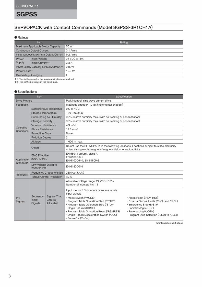
SERVOPACK with Contact Commands (Model SGPSS-3R1CH1A)
Item Rating
Maximum Applicable Motor Capacity 50 W
Continuous Output Current 3.1 Arms
Instantaneous Maximum Output Current 9.2 Arms
Power
Supply
Input Voltage 24 VDC ±15%
Input Current*2 3.3 A
Power Supply Capacity per SERVOPACK*1 215 W
Power Loss*2 10.9 W
Overvoltage Category I
Item Specification
Drive Method PWM control, sine wave current drive
Feedback Magnetic encoder: 10-bit (incremental encoder)
Operating
Conditions
Surrounding Air Temperature 0˚C to 40˚C
Storage Temperature −20˚C to 85˚C
Surrounding Air Humidity 90% relative humidity max. (with no freezing or condensation)
Storage Humidity 90% relative humidity max. (with no freezing or condensation)
Vibration Resistance 4.9 m/s2
Shock Resistance 19.6 m/s2
Protection Class None
Pollution Degree 2
Altitude 1,000 m max.
OthersDo not use the SERVOPACK in the following locations: Locations subject to static electricity
noise, strong electromagnetic/magnetic fields, or radioactivity.
Applicable
Standards
EMC Directive
2004/108/EC
EN 55011 group1, class A
EN 61000-6-2
EN 61000-6-4, EN 61800-3
Low Voltage Directive
2006/95/ECEN 61800-5-1
PerformancesFrequency Characteristics 250 Hz(JL=JM)Torque Control Precision* ±2%
I/O
Signals
Sequence
Input
Signals
Signals That
Can Be
Allocated
Allowable voltage range: 24 VDC ±10%
Number of input points: 13
Input method: Sink inputs or source inputs
Input signals:
Ratings
Specifications
・Mode Switch (/MODE)
・Program Table Operation Start (/START)
・Program Table Operation Stop (/STOP)
・Origin Return (/HOME)
・Program Table Operation Reset (/PGMRES)
・Origin Return Deceleration Switch (/DEC)
・Servo ON (/S-ON)
・Alarm Reset (/ALM-RST)
・External Torque Limits (/P-CL and /N-CL)
・Emergency Stop (E-STP)
・Forward Jog (/JOGP)
・Reverse Jog (/JOGN)
・Program Step Selection (/SEL0 to /SEL5)
*1: This is the value for the maximum instantaneous load.
*2: This is the net value at the rated load.
(Continued on next page.)
8
P05-15_KAEPS80000140B_1_0.indd 8 15.3.3 9:03:15 AM
SERVOPACKs
SGPSS
*: This is the repeatability of the output current from the SERVOPACK.
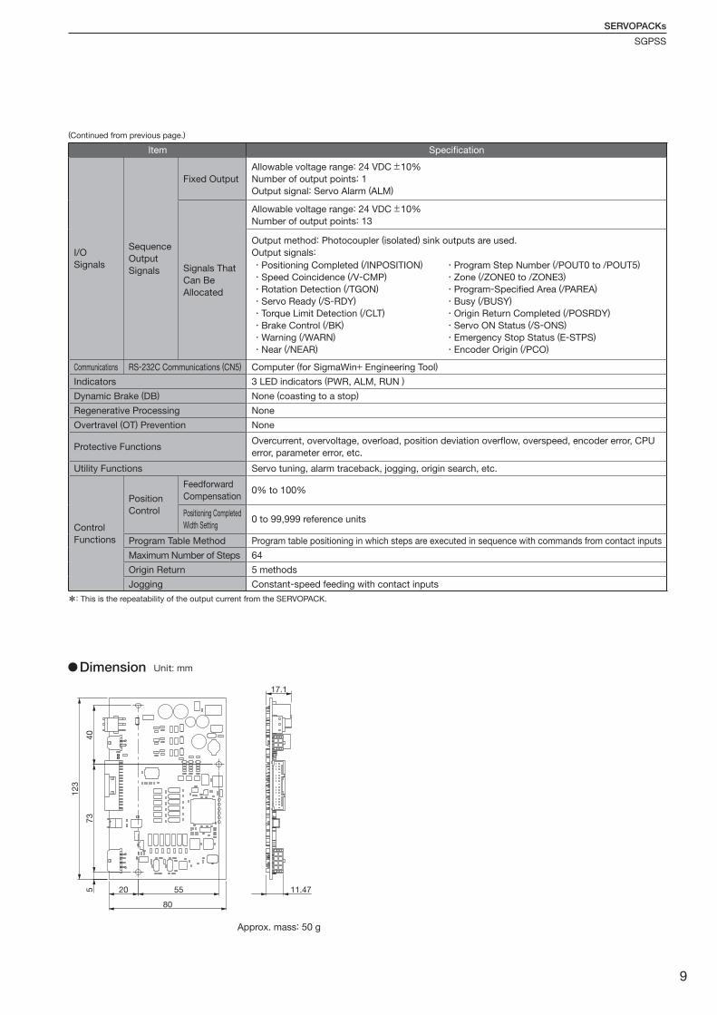
123
40
73
5 20 55
80
11.47
17.1
Dimension Unit: mm
Item Specification
I/O
Signals
Sequence
Output
Signals
Fixed Output
Allowable voltage range: 24 VDC ±10%
Number of output points: 1
Output signal: Servo Alarm (ALM)
Signals That
Can Be
Allocated
Allowable voltage range: 24 VDC ±10%
Number of output points: 13
Output method: Photocoupler (isolated) sink outputs are used.
Output signals:
Communications RS-232C Communications (CN5) Computer (for SigmaWin+ Engineering Tool)
Indicators 3 LED indicators (PWR, ALM, RUN )
Dynamic Brake (DB) None (coasting to a stop)
Regenerative Processing None
Overtravel (OT) Prevention None
Protective FunctionsOvercurrent, overvoltage, overload, position deviation overflow, overspeed, encoder error, CPU
error, parameter error, etc.
Utility Functions Servo tuning, alarm traceback, jogging, origin search, etc.
Control
Functions
Position
Control
Feedforward
Compensation0% to 100%
Positioning Completed
Width Setting0 to 99,999 reference units
Program Table Method Program table positioning in which steps are executed in sequence with commands from contact inputs
Maximum Number of Steps 64
Origin Return 5 methods
Jogging Constant-speed feeding with contact inputs
・Positioning Completed (/INPOSITION)
・Speed Coincidence (/V-CMP)
・Rotation Detection (/TGON)
・Servo Ready (/S-RDY)
・Torque Limit Detection (/CLT)
・Brake Control (/BK)
・Warning (/WARN)
・Near (/NEAR)
・Program Step Number (/POUT0 to /POUT5)
・Zone (/ZONE0 to /ZONE3)
・Program-Specified Area (/PAREA)
・Busy (/BUSY)
・Origin Return Completed (/POSRDY)
・Servo ON Status (/S-ONS)
・Emergency Stop Status (E-STPS)
・Encoder Origin (/PCO)
(Continued from previous page.)
Approx. mass: 50 g
9
P05-15_KAEPS80000140B_1_0.indd 9 15.3.3 9:03:15 AM
SERVOPACKs
SGPSS
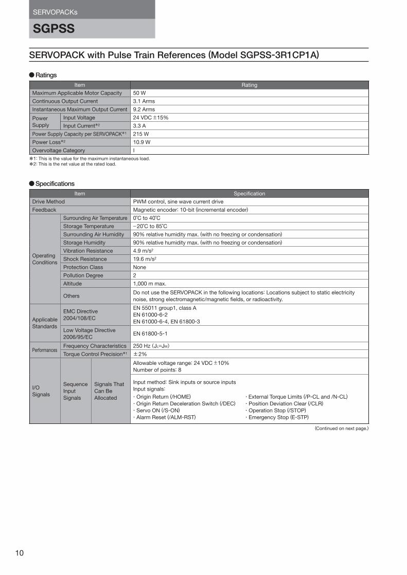
SERVOPACK with Pulse Train References (Model SGPSS-3R1CP1A)
Item Specification
Drive Method PWM control, sine wave current drive
Feedback Magnetic encoder: 10-bit (incremental encoder)
Operating
Conditions
Surrounding Air Temperature 0˚C to 40˚C
Storage Temperature −20˚C to 85˚C
Surrounding Air Humidity 90% relative humidity max. (with no freezing or condensation)
Storage Humidity 90% relative humidity max. (with no freezing or condensation)
Vibration Resistance 4.9 m/s2
Shock Resistance 19.6 m/s2
Protection Class None
Pollution Degree 2
Altitude 1,000 m max.
OthersDo not use the SERVOPACK in the following locations: Locations subject to static electricity
noise, strong electromagnetic/magnetic fields, or radioactivity.
Applicable
Standards
EMC Directive
2004/108/EC
EN 55011 group1, class A
EN 61000-6-2
EN 61000-6-4, EN 61800-3
Low Voltage Directive
2006/95/ECEN 61800-5-1
PerformancesFrequency Characteristics 250 Hz(JL=JM)Torque Control Precision*1 ±2%
I/O
Signals
Sequence
Input
Signals
Signals That
Can Be
Allocated
Allowable voltage range: 24 VDC ±10%
Number of points: 8
Input method: Sink inputs or source inputs
Input signals:
Specifications
・Origin Return (/HOME)
・Origin Return Deceleration Switch (/DEC)
・Servo ON (/S-ON)
・Alarm Reset (/ALM-RST)
・External Torque Limits (/P-CL and /N-CL)
・Position Deviation Clear (/CLR)
・Operation Stop (/STOP)
・Emergency Stop (E-STP)
Item Rating
Maximum Applicable Motor Capacity 50 W
Continuous Output Current 3.1 Arms
Instantaneous Maximum Output Current 9.2 Arms
Power
Supply
Input Voltage 24 VDC ±15%
Input Current*2 3.3 A
Power Supply Capacity per SERVOPACK*1 215 W
Power Loss*2 10.9 W
Overvoltage Category I
Ratings
*1: This is the value for the maximum instantaneous load.
*2: This is the net value at the rated load.
(Continued on next page.)
10
P05-15_KAEPS80000140B_1_0.indd 10 15.3.3 9:03:15 AM
SERVOPACKs
SGPSS
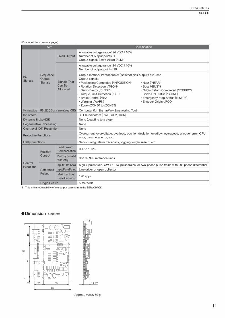
123
40
73
5 20 55
80
11.47
17.1
*: This is the repeatability of the output current from the SERVOPACK.
Dimension Unit: mm
Item Specification
I/O
Signals
Sequence
Output
Signals
Fixed Output
Allowable voltage range: 24 VDC ±10%
Number of output points: 1
Output signal: Servo Alarm (ALM)
Signals That
Can Be
Allocated
Allowable voltage range: 24 VDC ±10%
Number of output points: 10
Output method: Photocoupler (isolated) sink outputs are used.
Output signals:
Communications RS-232C Communications (CN5) Computer (for SigmaWin+ Engineering Tool)
Indicators 3 LED indicators (PWR, ALM, RUN)
Dynamic Brake (DB) None (coasting to a stop)
Regenerative Processing None
Overtravel (OT) Prevention None
Protective FunctionsOvercurrent, overvoltage, overload, position deviation overflow, overspeed, encoder error, CPU
error, parameter error, etc.
Utility Functions Servo tuning, alarm traceback, jogging, origin search, etc.
Control
Functions
Position
Control
Feedforward
Compensation0% to 100%
Positioning Completed
Width Setting0 to 99,999 reference units
Reference
Pulses
Input Pulse Types Sign + pulse train, CW + CCW pulse trains, or two-phase pulse trains with 90° phase differential
Input Pulse Forms Line driver or open collector
Maximum Input
Pulse Frequency120 kpps
Origin Return 5 methods
・Positioning Completed (/INPOSITION)
・Rotation Detection (/TGON)
・Servo Ready (/S-RDY)
・Torque Limit Detection (/CLT)
・Brake Control (/BK)
・Warning (/WARN)
・Zone (/ZONE0 to /ZONE3)
・Near (/NEAR)
・Busy (/BUSY)
・Origin Return Completed (/POSRDY)
・Servo ON Status (/S-ONS)
・Emergency Stop Status (E-STPS)
・Encoder Origin (/PCO)
(Continued from previous page.)
Approx. mass: 50 g
11
P05-15_KAEPS80000140B_1_0.indd 11 15.3.3 9:03:15 AM
Capacity Selection for Servomotors
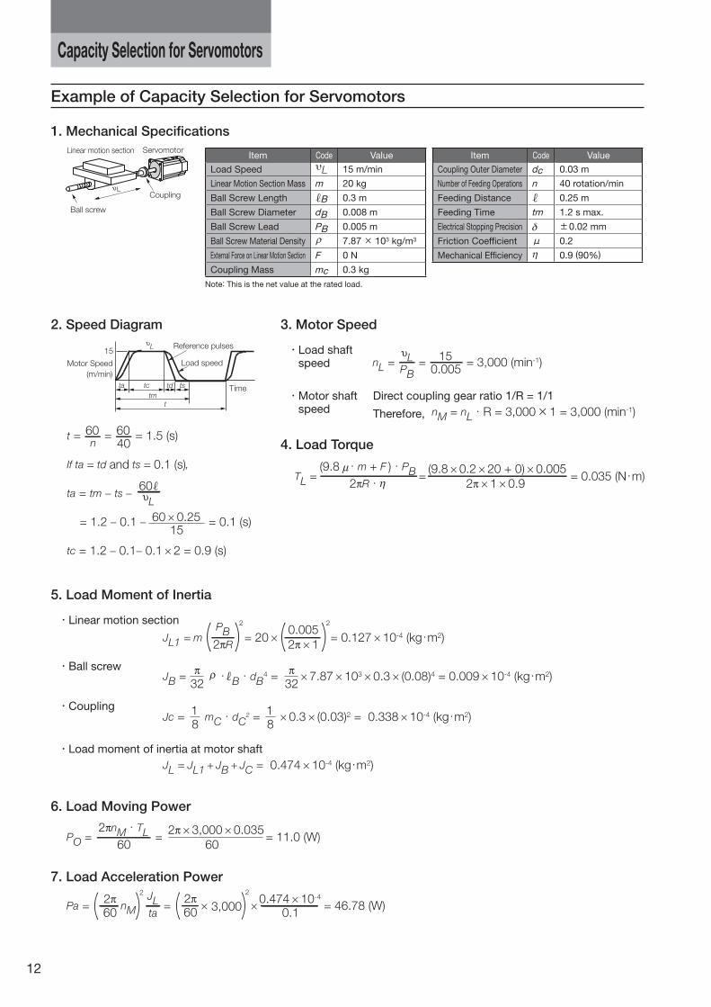
2. Speed Diagram 3. Motor Speed
・ Load shaftspeed
・ Motor shaft speed
Direct coupling gear ratio 1/R = 1/1
Therefore,
Item Code Value
Load Speed 15 m/min
Linear Motion Section Mass m 20 kg
Ball Screw Length B 0.3 m
Ball Screw Diameter dB 0.008 m
Ball Screw Lead PB 0.005 m
Ball Screw Material Density 7.87 × 10³ kg/m3
External Force on Linear Motion Section F 0 N
Coupling Mass mc 0.3 kg
Item Code Value
Coupling Outer Diameter dc 0.03 m
Number of Feeding Operations n 40 rotation/min
Feeding Distance 0.25 m
Feeding Time tm 1.2 s max.
Electrical Stopping Precision δ ±0.02 mm
Friction Coefficient μ 0.2
Mechanical Efficiency 0.9 (90%)
1. Mechanical Specifications
Note: This is the net value at the rated load.
Ball screw
ServomotorLinear motion section
CouplingL
Load speed
Reference pulses
(m/min)
Motor Speed
Timetm
15
tcta td ts
t
L
t = = = 1.5 (s)
If ta = td and ts = 0.1 (s),
ta = tm ts
= 1.2 0.1 = 0.1 (s)
tc = 1.2 0.1 0.1 2 = 0.9 (s)
60n
6040
60 0.2515
L60
nL = = = 3,000 (min-1)PB
150.005
L
TL = = = 0.035 (N・m)2 R・
(9.8 ・m + F )・PB2 1 0.9
(9.8 0.2 20 + 0) 0.005
nM = nL・R = 3,000 × 1 = 3,000 (min-1)
4. Load Torque
5. Load Moment of Inertia
・Linear motion section
・Ball screw
・Coupling
・Load moment of inertia at motor shaft
JL1 = m = 20 = 0.127 10-4 (kg・m2)
2
2 R
PB2
2 1
0.005
JB = ・ B・dB4 = 7.87 103 0.3 (0.08)4 = 0.009 10-4 (kg・m2)
32 32
Jc = mC・dC2 = 0.3 (0.03)2 = 0.338 10-4 (kg・m2)
81
81
JL = JL1 JB JC = 0.474 10-4 (kg・m2)
7. Load Acceleration Power
Pa = = = 46.78 (W)nM
2
602
ta
JL3,000
2
602
0.10.474 10-4
6. Load Moving Power
PO = = = 11.0 (W)60
2 nM・TL60
2 3,000 0.035
Example of Capacity Selection for Servomotors
12
P05-15_KAEPS80000140B_1_0.indd 12 15.3.3 9:03:16 AM
Capacity Selection for Servomotors
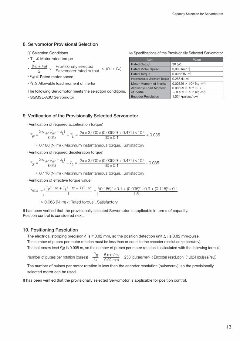
9. Verification of the Provisionally Selected Servomotor
・Verification of required acceleration torque:
It has been verified that the provisionally selected Servomotor is applicable in terms of capacity.
Position control is considered next.
・Verification of required deceleration torque:
・Verification of effective torque value:
8. Servomotor Provisional Selection
Selection Conditions Specifications of the Provisionally Selected Servomotor
・TL ≦ Motor rated torque
・nM≦ Rated motor speed
・SGMSL-A3C Servomotor
・JL≦ Allowable load moment of inertia
The following Servomotor meets the selection conditions.
・ < <2
(Po + Pa)(Po + Pa)
Provisionally selectedServomotor rated output
Item Value
Rated Output 30 (W)
Rated Motor Speed 3,000 (min-1)
Rated Torque 0.0955 (N m)
Instantaneous Maximum Torque 0.286 (N m)
Motor Moment of Inertia 0.00629 × 10⁻⁴ (kg m2)
Allowable Load Moment
of Inertia
0.00629 × 10-4 × 30
= 0.189 × 10⁻⁴ (kg m2)
Encoder Resolution 1,024 (pulses/rev)
TP = + TL = + 0.03560ta
2 nM (JM + JL)
60 0.1
2 3,000 (0.00629 + 0.474) 10-4
0.186 (N・m) <Maximum instantaneous torque...Satisfactory≈
TS = TL = 0.03560td
2 nM (JM + JL)
60 0.1
2 3,000 (0.00629 + 0.474) 10-4
0.116 (N・m) <Maximum instantaneous torque...Satisfactory≈
Trms = =t
TP2・ta + TL
2・tc + Ts2・td
1.5
(0.186)2 0.1 + (0.035)2 0.9 + (0.115)2 0.1
0.063 (N・m) < Rated torque...Satisfactory≈
10. Positioning ResolutionThe electrical stopping precision δ is ±0.02 mm, so the position detection unit is 0.02 mm/pulse.
The number of pulses per motor rotation must be less than or equal to the encoder resolution (pulses/rev).
The ball screw lead PB is 0.005 m, so the number of pulses per motor rotation is calculated with the following formula.
The number of pulses per motor rotation is less than the encoder resolution (pulses/rev), so the provisionally
selected motor can be used.
Number of pulses per rotation (pulses) = = = 250 (pulses/rev) < Encoder resolution〔1,024 (pulses/rev)〕PB
0.02 mm
5 mm/rev
It has been verified that the provisionally selected Servomotor is applicable for position control.
13
P05-15_KAEPS80000140B_1_0.indd 13 15.3.3 9:03:16 AM
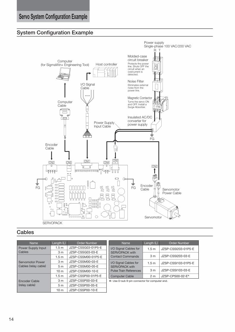
System Configuration Example
Cables
Servo System Configuration Example
Computer(for SigmaWin+ Engineering Tool)
FG FG
FG
I/O SignalCable
ComputerCable
EncoderCable
SERVOPACK
Host controller
Molded-casecircuit breaker
Power supplySingle-phase 100 VAC/200 VAC
R T
Insulated AC/DCconverter forpower supply
Power SupplyInput Cable
Servomotor
ServomotorPower Cable
EncoderCable
CN2
CN2
CN5 CN4CN1 CN3
Protects the power line. Shuts OFF the circuit when an overcurrent is detected.
Noise FilterEliminates external noise from the power line.
Magnetic ContactorTurns the servo ON and OFF. Install a Surge Absorber.
Name Length (L) Order Number
Power Supply Input
Cables
1.5 m JZSP-CSSG03-01P5-E
3 m JZSP-CSSG03-03-E
Servomotor Power
Cables (relay cable)
1.5 m JZSP-CSSM00-01P5-E
3 m JZSP-CSSM00-03-E
5 m JZSP-CSSM00-05-E
10 m JZSP-CSSM00-10-E
Encoder Cable(relay cable)
1.5 m JZSP-CSSP00-01P5-E
3 m JZSP-CSSP00-03-E
5 m JZSP-CSSP00-05-E
10 m JZSP-CSSP00-10-E
Name Length (L) Order Number
I/O Signal Cables for
SERVOPACK with
Contact Commands
1.5 m JZSP-CSSI203-01P5-E
3 m JZSP-CSSI203-03-E
I/O Signal Cables for
SERVOPACK with
Pulse Train References
1.5 m JZSP-CSSI103-01P5-E
3 m JZSP-CSSI103-03-E
Computer Cable 2 m JZSP-CPS00-02-E*
*: Use D-sub 9-pin connector for computer end.
14
P05-15_KAEPS80000140B_1_0.indd 14 15.3.3 9:03:17 AM
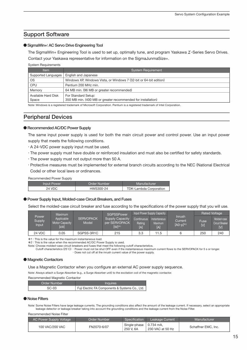
Servo System Configuration Example
Peripheral Devices
Support Software
Power Supply Input, Molded-case Circuit Breakers, and Fuses
Magnetic Contactors
Noise Filters
Input Power Order Number Manufacturer
24 VDC HWS300-24 TDK-Lambda Corporation
Order Number Inquires
SC-03 Fuji Electric FA Components & Systems Co., Ltd.
AC Power Supply Voltage Order Number Specification Leakage Current Manufacturer
100 VAC/200 VAC FN2070-6/07Single-phase
250 V, 6A
0.734 mA,
230 VAC at 50 HzSchaffner EMC, Inc.
Item System Requirement
Supported Languages English and Japanese
OS Windows XP, Windows Vista, or Windows 7 (32-bit or 64-bit edition)
CPU Pentium 200 MHz min.
Memory 64 MB min. (96 MB or greater recommended)
Available Hard Disk
Space
For Standard Setup:
350 MB min. (400 MB or greater recommended for installation)
Power
Supply
Input
Maximum
Applicable
Motor Capacity[kW]
SERVOPACK
Model
SGPSSPower
Supply Capacity
per SERVOPACK[W]*1
Input Power Supply CapacityInrush
Current[A0-p]*2
Rated Voltage
Continuous
Rating[A]
Instantaneous
Maximum[A]
Fuse[V]
Molded-case
Circuit Breaker[V]
24 VDC 0.05 SGPSS-3R1C 215 3.3 11.5 6 250 240
Recommended AC/DC Power Supply
SigmaWin+: AC Servo Drive Engineering Tool
The same input power supply is used for both the main circuit power and control power. Use an input power
supply that meets the following conditions.
・ A 24-VDC power supply input must be used.
・ The power supply must have double or reinforced insulation and must also be certified for safety standards.
・ The power supply must not output more than 50 A.
・ Protective measures must be implemented for external branch circuits according to the NEC (National Electrical
Code) or other local laws or ordinances.
The SigmaWin+ Engineering Tool is used to set up, optimally tune, and program Yaskawa -Series Servo Drives.
Contact your Yaskawa representative for information on the SigmaJunmaSize+.
Select the molded-case circuit breaker and fuse according to the specifications of the power supply that you will use.
Use a Magnetic Contactor when you configure an external AC power supply sequence.
Note: Always attach a Surge Absorber (e.g., a Surge Absorber unit) to the excitation coil of the magnetic contactor.
Note: Some Noise Filters have large leakage currents. The grounding conditions also affect the amount of the leakage current. If necessary, select an appropriate leakage detector or leakage breaker taking into account the grounding conditions and the leakage current from the Noise Filter.
Recommended Power Supply
Recommended Magnetic Contactor
Recommended Noise Filter
System Requirements
*1 : This is the value for the maximum instantaneous load.
*2 : This is the value when the recommended AC/DC Power Supply is used.Note: Choose molded-case circuit breakers and fuses that meet the following cutoff characteristics.
Cutoff characteristics (25°C): ・ Power must not be shut OFF even if the instantaneous maximum current flows to the SERVOPACK for 5 s or longer.・ Does not cut off at the inrush current value of the power supply.
Note: Windows is a registered trademark of Microsoft Corporation. Pentium is a registered trademark of Intel Corporation.
15
P05-15_KAEPS80000140B_1_0.indd 15 15.3.3 9:03:17 AM
LITERATURE NO. KAEP S800001 40B
14-11-12Published in Japan March 2015 14-7
In the event that the end user of this product is to be the military and said product is to be employed in any weapons systems or the manufacture thereof, the export will fall under the relevant regulations as stipulated in the Foreign Exchange and Foreign Trade Regulations. Therefore, be sure to follow all procedures and submit all relevant documentation according to any and all rules, regulations and laws that may apply.
Specifications are subject to change without notice for ongoing product modifications and improvements.
© 2014-2015 YASKAWA ELECTRIC CORPORATION. All rights reserved.
YASKAWA ELECTRIC CORPORATION
SERIES
1 -0
IRUMA BUSINESS CENTER (SOLUTION CENTER)480, Kamifujisawa, Iruma, Saitama, 358-8555, Japan
Phone 81-4-2962-5151 Fax 81-4-2962-6138
http://www.yaskawa.co.jp
YASKAWA AMERICA, INC.2121, Norman Drive South, Waukegan, IL 60085, U.S.A.
Phone 1-800-YASKAWA (927-5292) or 1-847-887-7000 Fax 1-847-887-7310
http://www.yaskawa.com
YASKAWA ELÉTRICO DO BRASIL LTDA.777, Avenida Piraporinha, Diadema, São Paulo, 09950-000, Brasil
Phone 55-11-3585-1100 Fax 55-11-3585-1187
http://www.yaskawa.com.br
YASKAWA EUROPE GmbH185, Hauptstraβe, Eschborn, 65760, Germany
Phone 49-6196-569-300 Fax 49-6196-569-398
http://www.yaskawa.eu.com
YASKAWA ELECTRIC KOREA CORPORATION9F, Kyobo Securities Bldg., 26-4, Yeouido-dong, Yeongdeungpo-gu, Seoul, 150-737, Korea
Phone 82-2-784-7844 Fax 82-2-784-8495
http://www.yaskawa.co.kr
YASKAWA ELECTRIC (SINGAPORE) PTE. LTD.151, Lorong Chuan, #04-02A, New Tech Park 556741, Singapore
Phone 65-6282-3003 Fax 65-6289-3003
http://www.yaskawa.com.sg
YASKAWA ELECTRIC (THAILAND) CO., LTD.252/125-126, 27th Floor, Muang Thai-Phatra Tower B, Rachadapisek Road, Huaykwang, Bangkok, 10310, Thailand
Phone 66-2693-2200 Fax 66-2693-4200
http://www.yaskawa.co.th
YASKAWA ELECTRIC (CHINA) CO., LTD.22F, One Corporate Avenue, No.222, Hubin Road, Shanghai, 200021, China
Phone 86-21-5385-2200 Fax 86-21-5385-3299
http://www.yaskawa.com.cn
YASKAWA ELECTRIC (CHINA) CO., LTD. BEIJING OFFICERoom 1011, Tower W3 Oriental Plaza, No.1, East Chang An Ave.,
Dong Cheng District, Beijing, 100738, China
Phone 86-10-8518-4086 Fax 86-10-8518-4082
YASKAWA ELECTRIC TAIWAN CORPORATION9F, 16, Nanking E. Rd., Sec. 3, Taipei, 104, Taiwan
Phone 886-2-2502-5003 Fax 886-2-2505-1280
http://www.yaskawa-taiwan.com.tw