AC & RLC Circuits...ACT: AC Circuit Voltages An AC circuit with R = 2 Ω, C = 15 mF, and L = 30 mH...
19
Physics 102: Lecture 12 AC & RLC Circuits L L R Physics 102: Lecture 12, Slide 1 C
Transcript of AC & RLC Circuits...ACT: AC Circuit Voltages An AC circuit with R = 2 Ω, C = 15 mF, and L = 30 mH...
Physics 102: Lecture 12
AC & RLC Circuits
LL
R
Physics 102: Lecture 12, Slide 1C
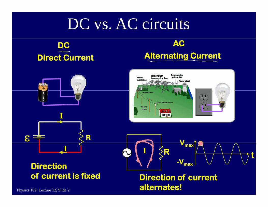
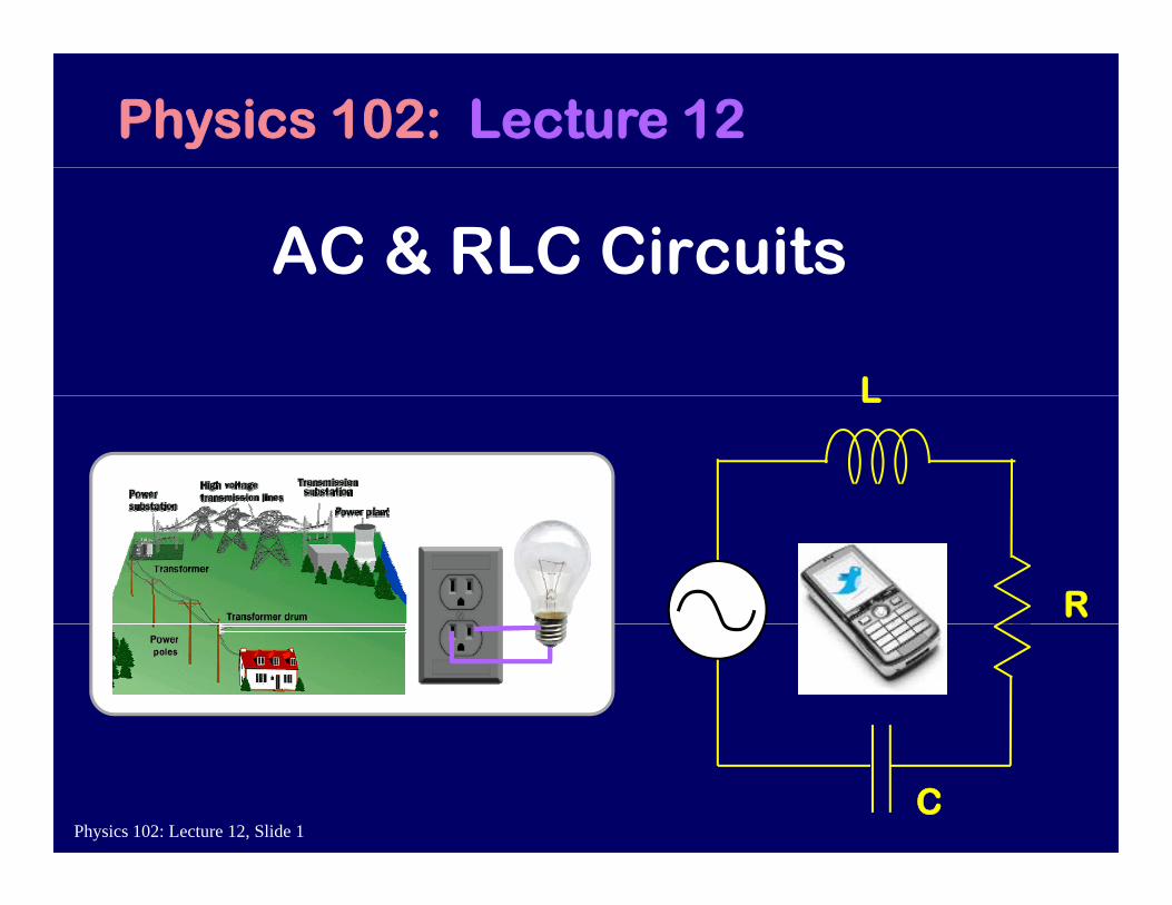
DC vs. AC circuitsAC
Alternating CurrentDC
Direct Current
I
Rε
I
VI
Direction
R t
Vmax
-Vmax
I
Physics 102: Lecture 12, Slide 2
Directionof current is fixed Direction of current
alternates!
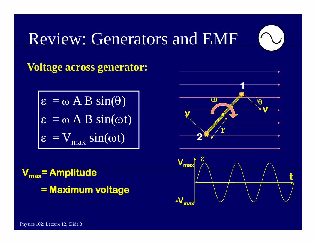
Review: Generators and EMFVoltage across generator:
•θωε = ω A B sin(θ)
1
vv
x r
( )ε = ω A B sin(ωt)ε = V sin(ωt) 2ε = Vmax sin(ωt) 2
εVmax
tVmax= Amplitude
= Maximum voltageV
Physics 102: Lecture 12, Slide 3
-Vmax
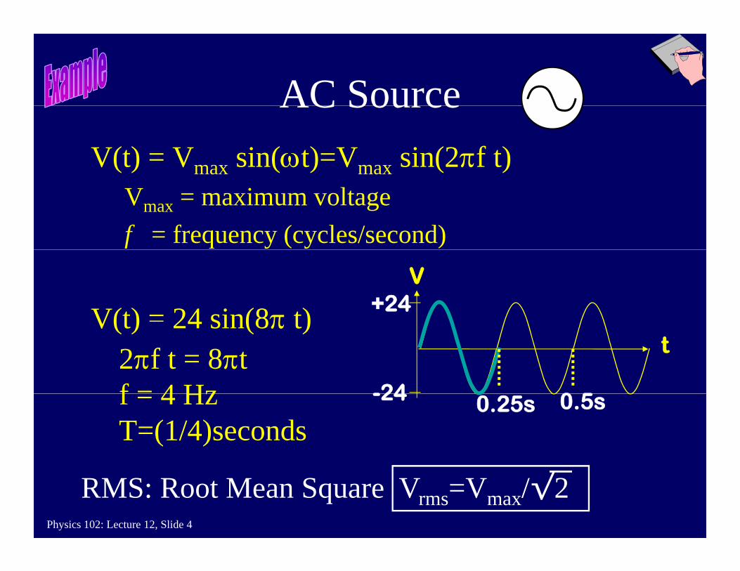
AC SourceAC Source V(t) = Vmax sin(ωt)=Vmax sin(2πf t)
Vmax = maximum voltagef = frequency (cycles/second)
+24V(t) = 24 sin(8π t)V
0 5
2πf t = 8πtf = 4 Hz -24
V(t) 24 sin(8π t)t
0.25s 0.5sf = 4 HzT=(1/4)seconds
-24
Physics 102: Lecture 12, Slide 4
RMS: Root Mean Square Vrms=Vmax/√2
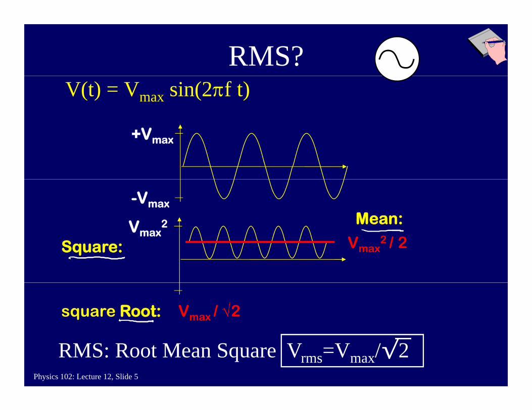
RMS?V(t) = Vmax sin(2πf t)
+Vmax
-Vmax
Vmax2 Mean:Vmax
Square: Vmax2 / 2
square Root: Vmax / √2
Physics 102: Lecture 12, Slide 5
RMS: Root Mean Square Vrms=Vmax/√2
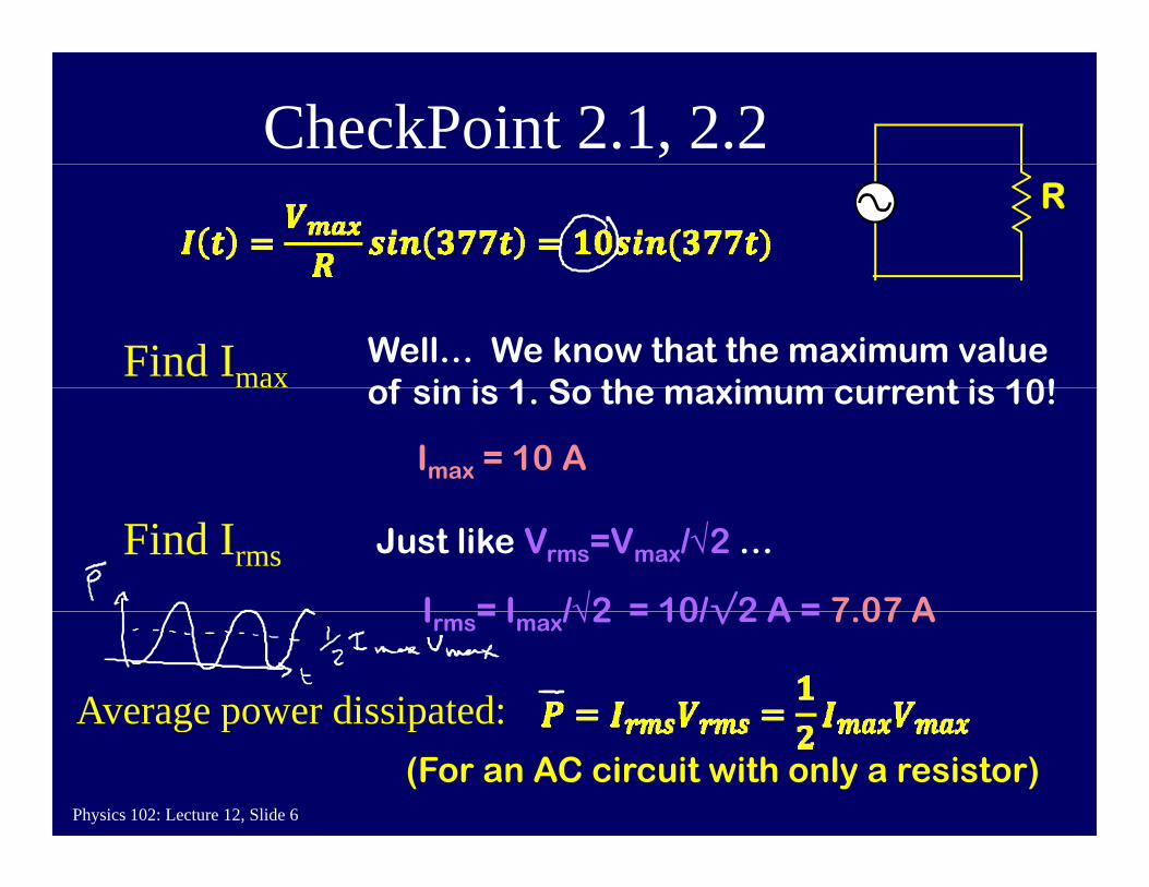
CheckPoint 2.1, 2.2R
Find ImaxWell… We know that the maximum value of sin is 1 So the maximum current is 10!of sin is 1. So the maximum current is 10!
Imax = 10 A
Find Irms Just like Vrms=Vmax/√2 …
I = I /√2 = 10/√2 A = 7 07 AIrms= Imax/√2 = 10/√2 A = 7.07 A
Average power dissipated:
Physics 102: Lecture 12, Slide 6
Average power dissipated:(For an AC circuit with only a resistor)
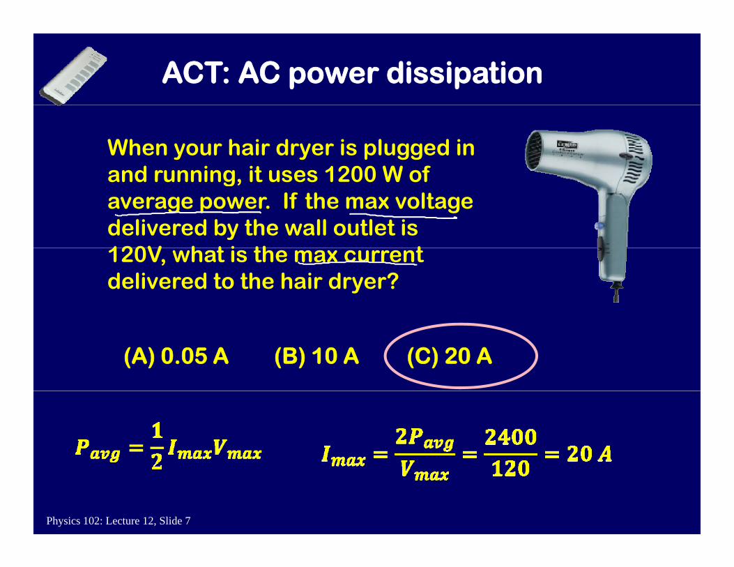
ACT: AC power dissipation
When your hair dryer is plugged in and running it uses 1200 W of and running, it uses 1200 W of average power. If the max voltage delivered by the wall outlet is 120V h t i th t 120V, what is the max current delivered to the hair dryer?
(C) 20 A(A) 0.05 A (B) 10 A
Physics 102: Lecture 12, Slide 7
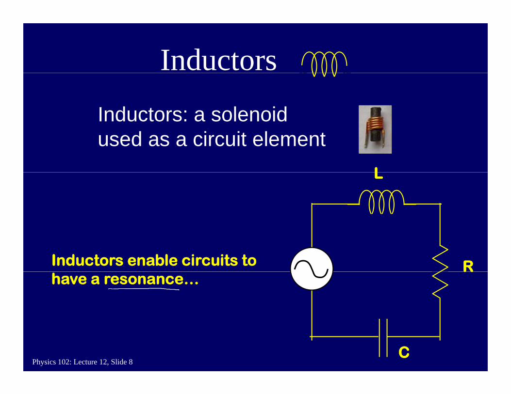
Inductors
Inductors: a solenoid
L
used as a circuit elementL
RInductors enable circuits to Rhave a resonance…
Physics 102: Lecture 12, Slide 8C
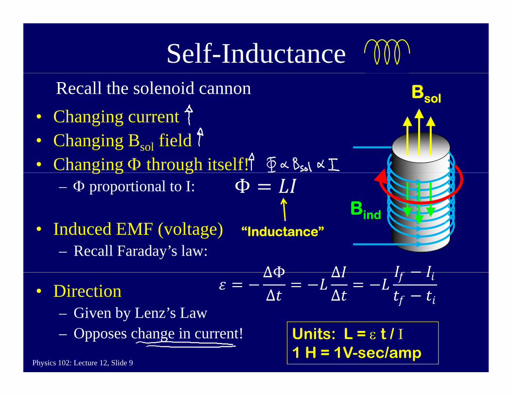
Self-Inductance
• Changing current Bsol
Recall the solenoid cannong g
• Changing Bsol field• Changing Φ through itself!g g g
– Φ proportional to I:
d d ( l )Bind
• Induced EMF (voltage)– Recall Faraday’s law:
“Inductance”
∆Φ ∆• Direction
– Given by Lenz’s Law
∆ΦΔ
∆Δ
Physics 102: Lecture 12, Slide 9
– Opposes change in current! Units: L = ε t / I1 H = 1V-sec/amp
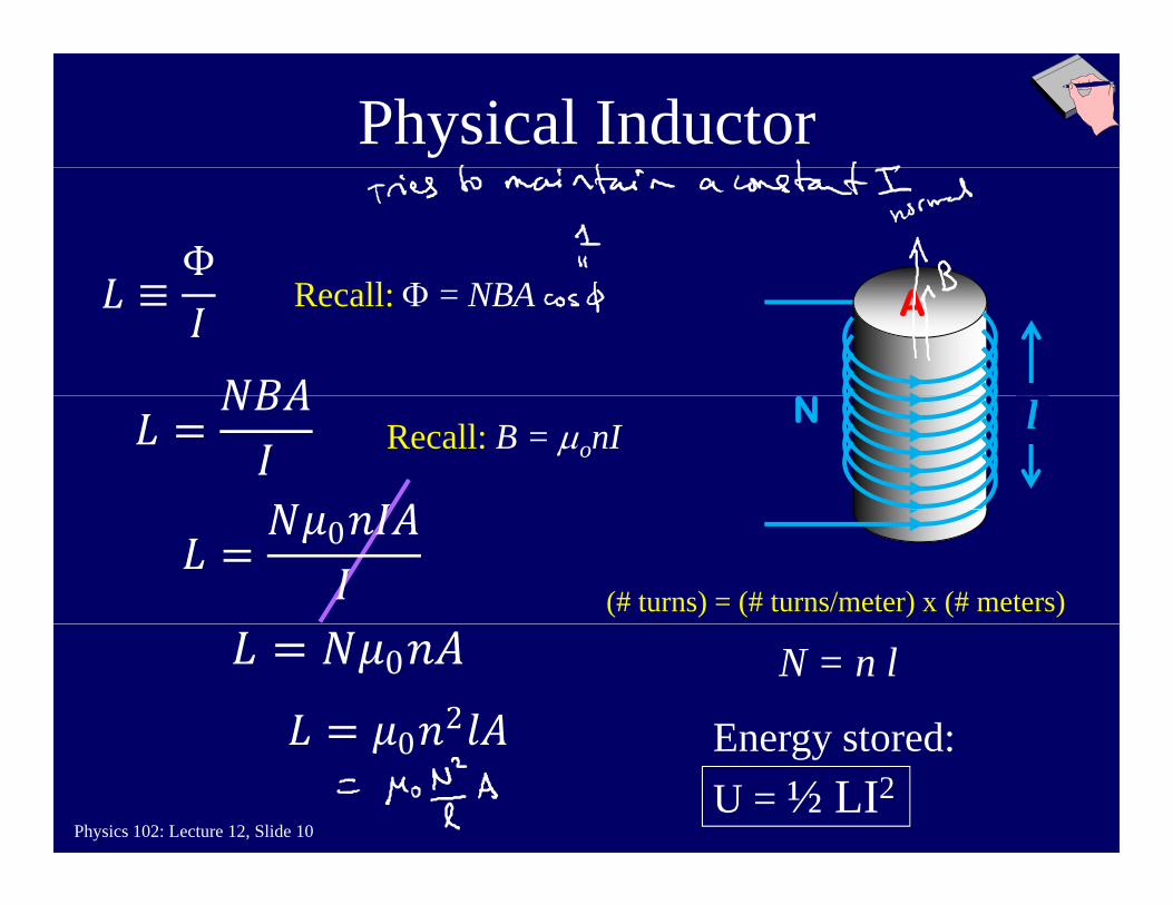
Physical Inductor
Recall: Φ = NBA A
Recall: B = μonIN l
(# turns) = (# turns/meter) x (# meters)
0
N = n l
Energy stored:
0
02
Physics 102: Lecture 12, Slide 10
Energy stored:U = ½ LI2
0
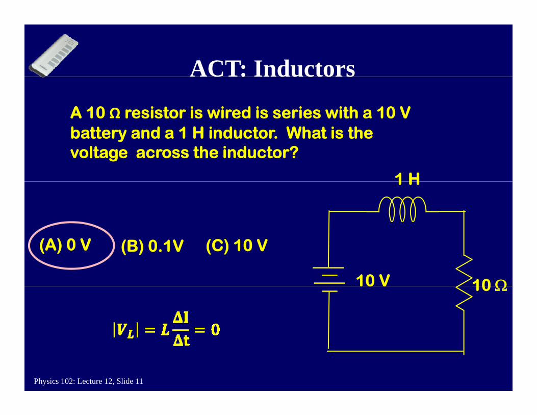
ACT: InductorsC : duc o s
A 10 Ω resistor is wired is series with a 10 V b tt d 1 H i d t Wh t i th
1 H
battery and a 1 H inductor. What is the voltage across the inductor?
1 H
10 Ω10 V
(A) 0 V (C) 10 V(B) 0.1V
10 Ω10 V
Physics 102: Lecture 12, Slide 11
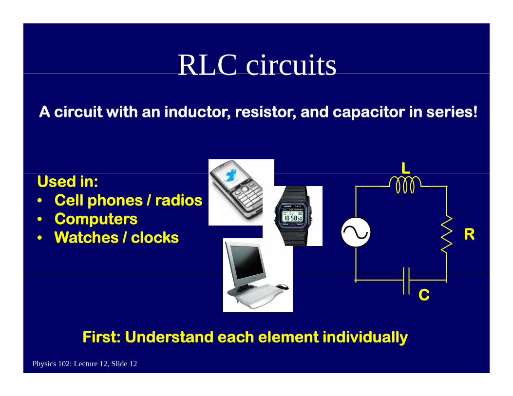
RLC circuitsRLC circuitsA circuit with an inductor, resistor, and capacitor in series!
LLUsed in:• Cell phones / radios• Computers
RComputers
• Watches / clocks
C
Physics 102: Lecture 12, Slide 12
First: Understand each element individually

Resistors in AC circuitVR = I R always true – Ohm’s Law R
• VR,max = ImaxR• Voltage across resistor is “IN PHASE” with current.
– VR goes up and down at the same times as I does.
I
tt
e (
R)
t
VR
ista
nc
e
Frequency does notff t R i t !
Physics 102: Lecture 12, Slide 13FrequencyR
es affect Resistance!
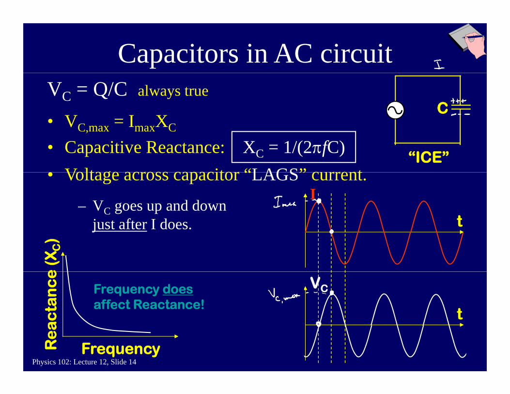
Capacitors in AC circuit
CVC = Q/C always true
• V = I X
• Voltage across capacitor “LAGS” current
• VC,max = ImaxXC
• Capacitive Reactance: XC = 1/(2πfC)“ICE”
I
t
• Voltage across capacitor “LAGS” current.
– VC goes up and down j t ft I d tjust after I does.
e (
XC)
t
VC
cta
nc
e
Frequency doesaffect Reactance!
Physics 102: Lecture 12, Slide 14FrequencyR
ea
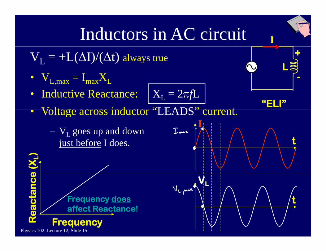
Inductors in AC circuit I
LVL = +L(ΔI)/(Δt) always true
• V = I X
+
-
• Voltage across inductor “LEADS” current
• VL,max = ImaxXL
• Inductive Reactance: XL = 2πfL“ELI”
I
t
• Voltage across inductor “LEADS” current.
– VL goes up and down j t b f I d tjust before I does.
e (
XL)
t
VL
cta
nc
e
Frequency does
Physics 102: Lecture 12, Slide 15FrequencyR
ea affect Reactance!
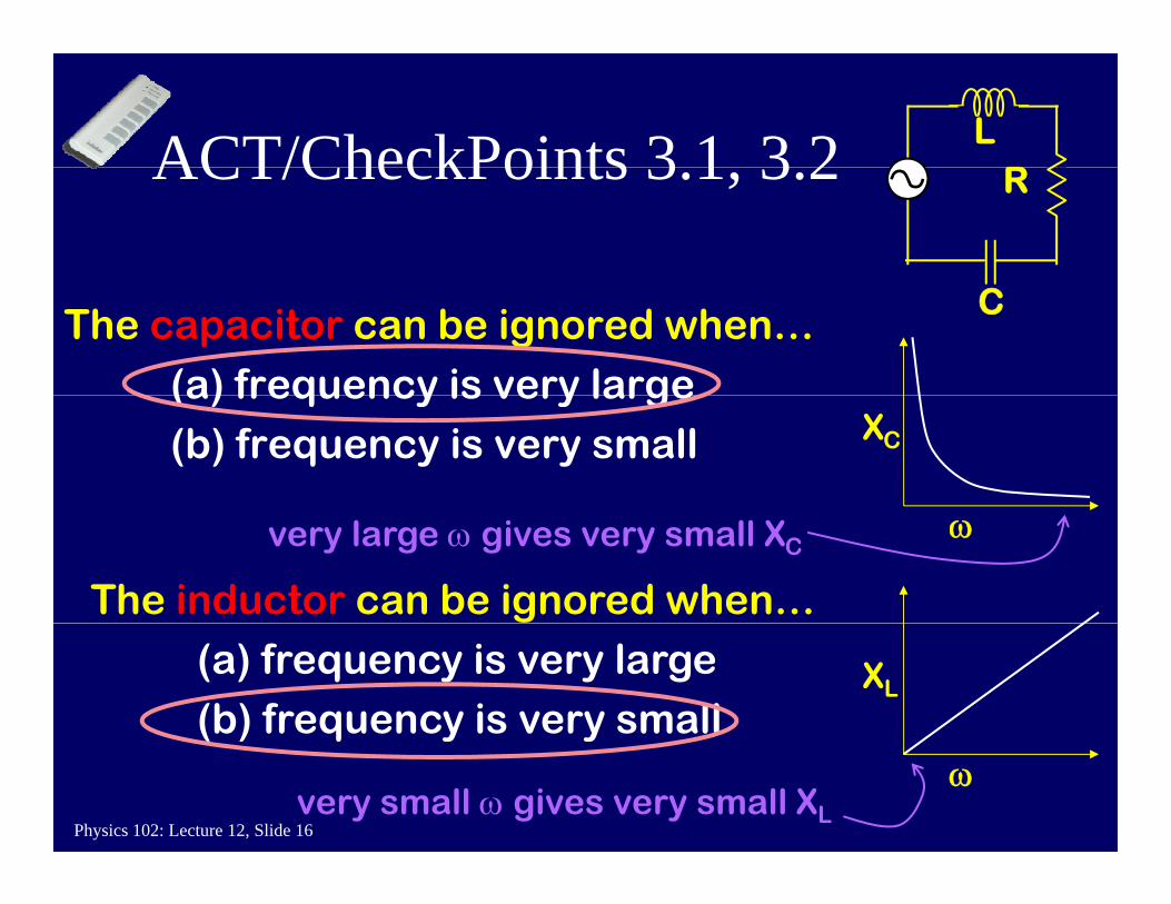
ACT/CheckPoints 3 1 3 2 LRACT/CheckPoints 3.1, 3.2 R
The capacitor can be ignored when…(a) frequency is very large
C
(a) frequency is very large(b) frequency is very small XC
The inductor can be ignored when…
ωvery large ω gives very small XC
(a) frequency is very large(b) frequency is very small
XL
Physics 102: Lecture 12, Slide 16
( ) q y yω
very small ω gives very small XL
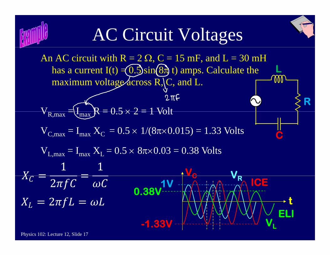
AC Circuit VoltagesAn AC circuit with R = 2 Ω, C = 15 mF, and L = 30 mH
has a current I(t) = 0.5 sin(8π t) amps. Calculate the i lt R C d L
Lmaximum voltage across R, C, and L.
V = I R = 0 5 × 2 = 1 VoltR
VR,max = Imax R = 0.5 × 2 = 1 Volt
= 0.5 × 1/(8π×0.015) = 1.33 VoltsVC,max = Imax XC C
= 0.5 × 8π×0.03 = 0.38 VoltsVL,max = Imax XL
VC V
t
C VR ICE1V0.38V
Physics 102: Lecture 12, Slide 17
VL
ELI-1.33V
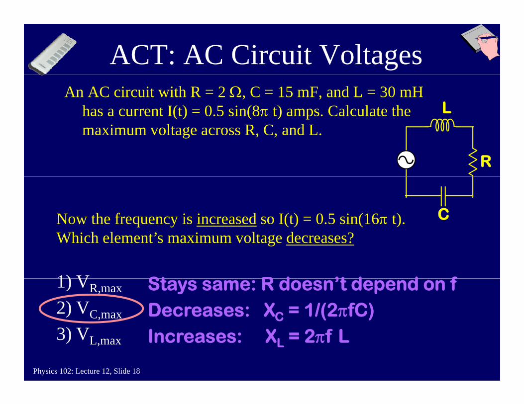
ACT: AC Circuit VoltagesAn AC circuit with R = 2 Ω, C = 15 mF, and L = 30 mH
has a current I(t) = 0.5 sin(8π t) amps. Calculate the i lt R C d L
Lmaximum voltage across R, C, and L.
R
Now the frequency is increased so I(t) = 0.5 sin(16π t). C
Which element’s maximum voltage decreases?
1) V St R d ’t d d f1) VR,max
2) VC,max
3) V
Stays same: R doesn’t depend on fDecreases: XC = 1/(2πfC)I X 2 f L
Physics 102: Lecture 12, Slide 18
3) VL,max Increases: XL = 2πf L
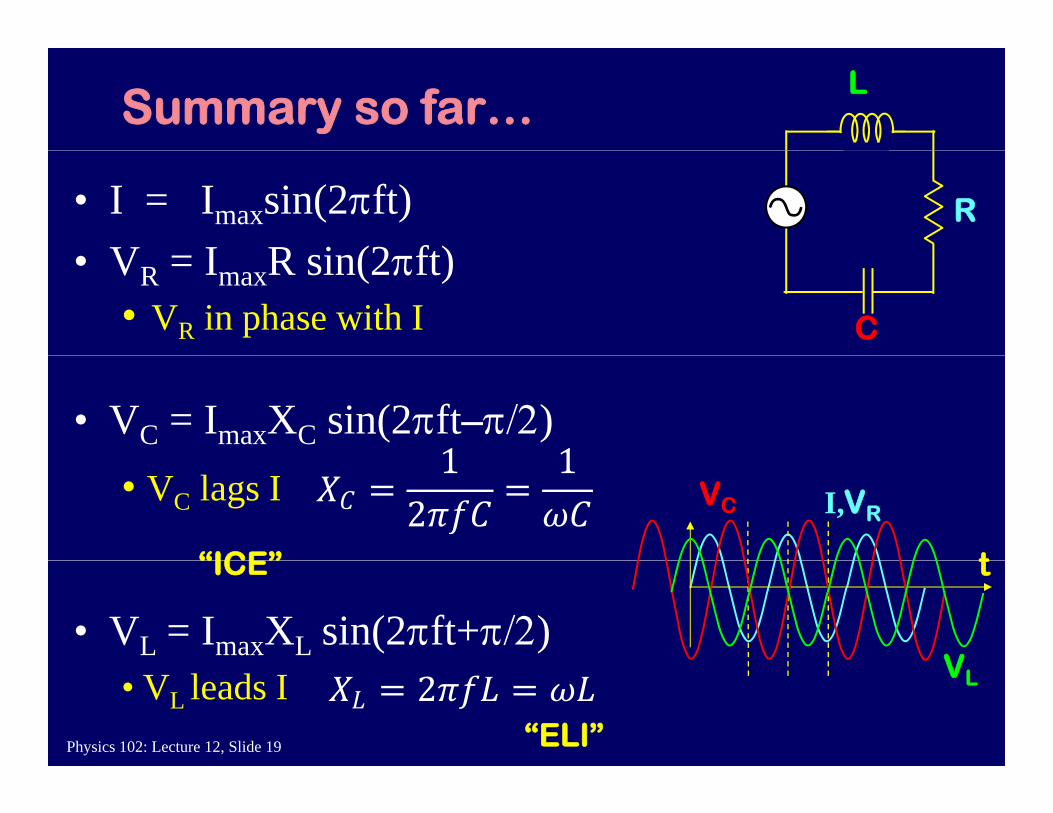
Summary so far…L
R• I = Imaxsin(2πft)V I R i (2 ft)
C
• VR = ImaxR sin(2πft) • VR in phase with I
• VC = ImaxXC sin(2πft–π/2) • VC lags I I,
t
VC VR
“ICE”
• VL = ImaxXL sin(2πft+π/2) t
V
“ICE”
Physics 102: Lecture 12, Slide 19
• VL leads I VL
“ELI”