A gravitational wave is a differential strain in spacetime ...A gravitational wave is a differential...
26
Transcript of A gravitational wave is a differential strain in spacetime ...A gravitational wave is a differential...
2
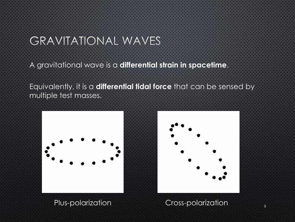
A gravitational wave is a differential strain in spacetime.
Equivalently, it is a differential tidal force that can be sensed by
multiple test masses.
Plus-polarization Cross-polarization
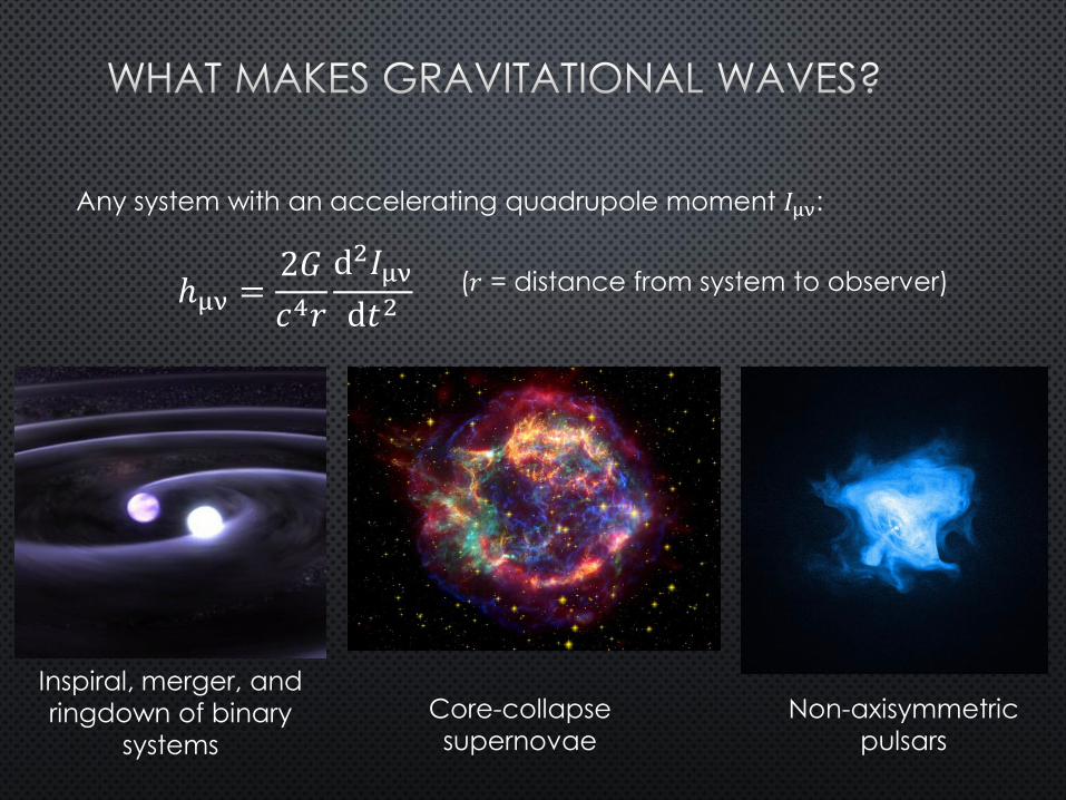
Any system with an accelerating quadrupole moment 𝐼μν:
ℎμν =2𝐺
𝑐4𝑟
d2𝐼μν
d𝑡2 (𝑟 = distance from system to observer)
Inspiral, merger, and
ringdown of binary
systems
Core-collapse
supernovae
Non-axisymmetric
pulsars
4
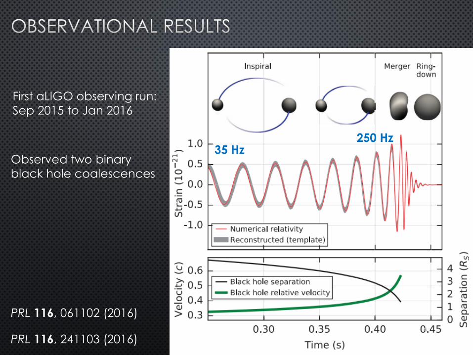
35 Hz 250 Hz
First aLIGO observing run:
Sep 2015 to Jan 2016
Observed two binary
black hole coalescences
PRL 116, 061102 (2016)
PRL 116, 241103 (2016)
5
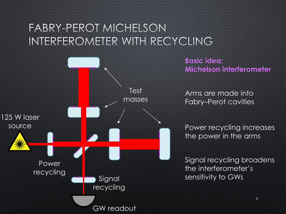
Test
masses
Power
recycling
Power recycling increases
the power in the arms
Signal
recycling
Signal recycling broadens
the interferometer’s
sensitivity to GWs
GW readout
125 W laser
source
Basic idea:
Michelson interferometer
Arms are made into
Fabry–Perot cavities
6
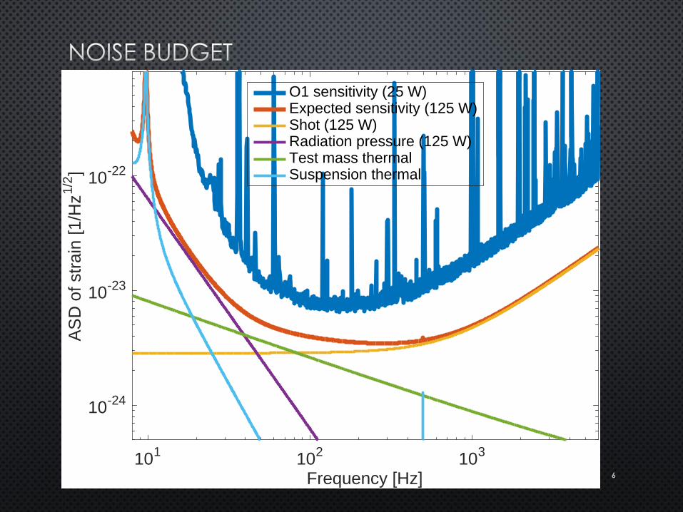
101
102
103
Frequency [Hz]
10-24
10-23
10-22
AS
D o
f str
ain
[1
/Hz
1/2
]O1 sensitivity (25 W)Expected sensitivity (125 W)Shot (125 W)Radiation pressure (125 W)Test mass thermalSuspension thermal
7
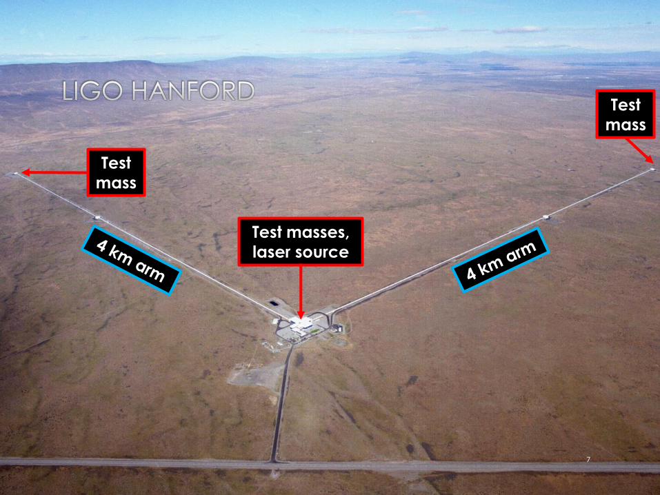
Test
mass
Test
mass
Test masses,
laser source
8
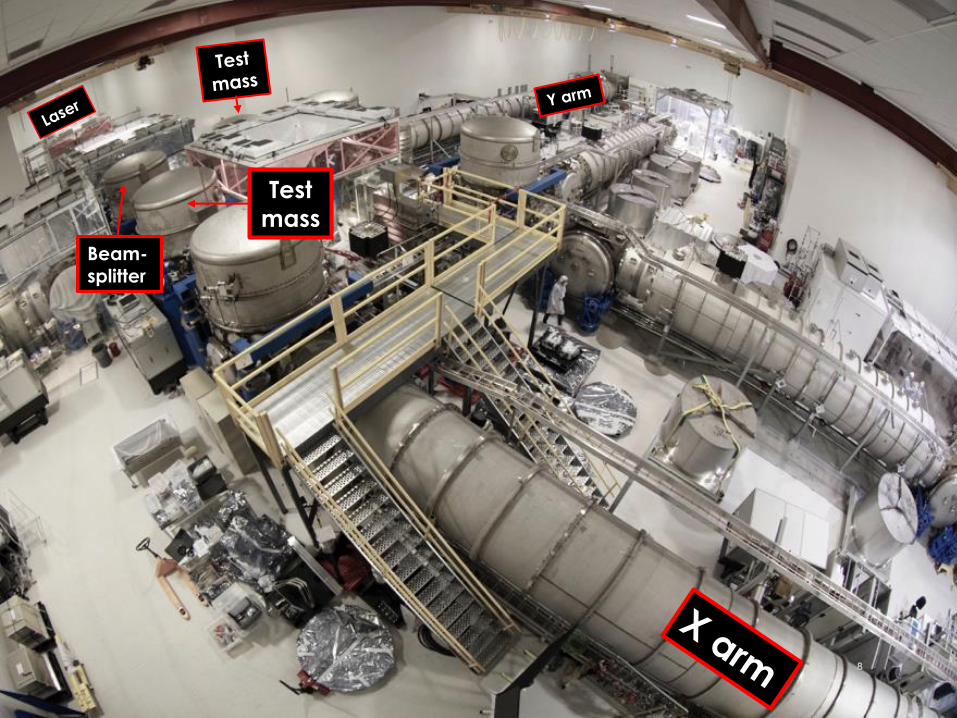
Test
mass
Beam- splitter
9
10
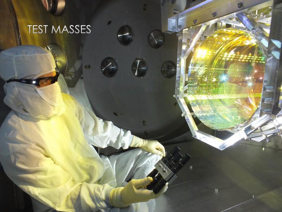
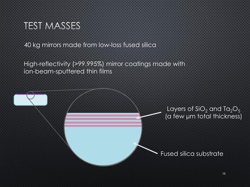
Layers of SiO2 and Ta2O5
(a few µm total thickness)
High-reflectivity (>99.995%) mirror coatings made with
ion-beam-sputtered thin films
Fused silica substrate
40 kg mirrors made from low-loss fused silica
11
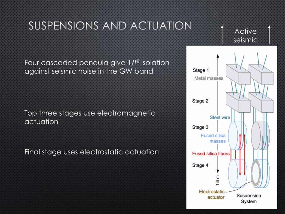
Active
seismic
isolation
Four cascaded pendula give 1/f8 isolation
against seismic noise in the GW band
Top three stages use electromagnetic
actuation
Final stage uses electrostatic actuation
12
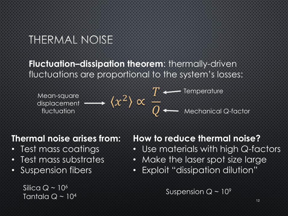
Fluctuation–dissipation theorem: thermally-driven
fluctuations are proportional to the system’s losses:
How to reduce thermal noise?
• Use materials with high Q-factors
• Make the laser spot size large
• Exploit “dissipation dilution”
𝑥2 ∝ 𝑇
𝑄
Mean-square
displacement
fluctuation
Temperature
Mechanical Q-factor
Thermal noise arises from: • Test mass coatings
• Test mass substrates
• Suspension fibers
Silica Q ~ 106
Tantala Q ~ 104 Suspension Q ~ 109
13
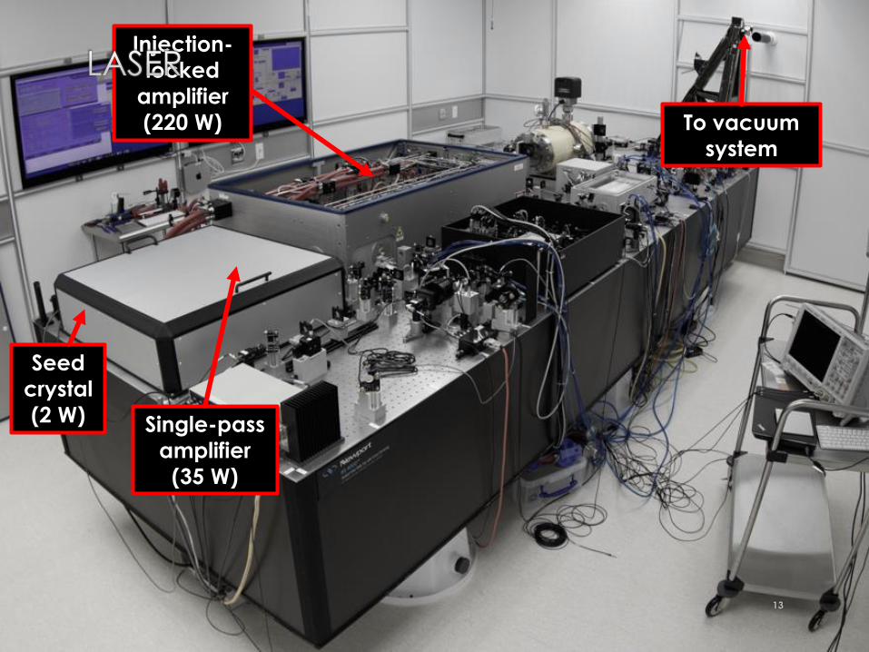
Seed
crystal
(2 W) Single-pass
amplifier
(35 W)
Injection-
locked
amplifier
(220 W) To vacuum
system
14
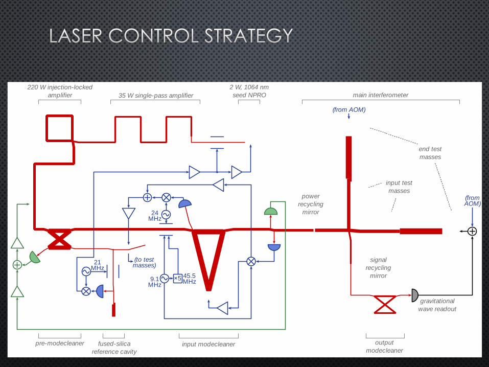
35 W single-pass amplifier
220 W injection-locked
amplifier
input modecleaner output
modecleaner
2 W, 1064 nm
seed NPRO main interferometer
fused-silica
reference cavity
24MHz
×59.1MHz
45.5MHz
21MHz
(to test masses)
(from AOM)
(fromAOM)
power
recycling
mirror
signal
recycling
mirror
pre-modecleaner
input test
masses
end test
masses
gravitational
wave readout
Laser power: 125 W of 1064 nm light into interferometer
Laser noise: must contribute no more than one tenth of
the total GW strain ASD
Laser noise affects GW readout because of arm
imbalances:
• Different input test mass reflectivties
• Different arm losses
• Beamsplitter not perfectly 50/50
• Differential arm length offset
15
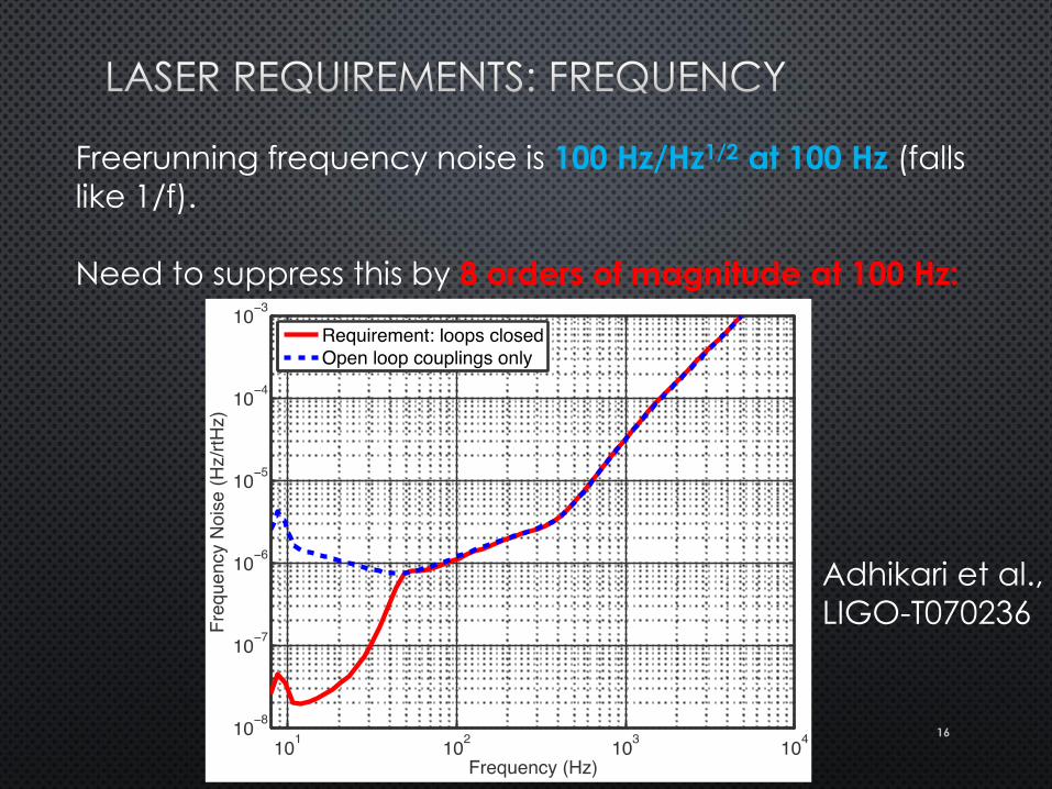
Freerunning frequency noise is 100 Hz/Hz1/2 at 100 Hz (falls
like 1/f).
Need to suppress this by 8 orders of magnitude at 100 Hz:
Adhikari et al.,
LIGO-T070236
16
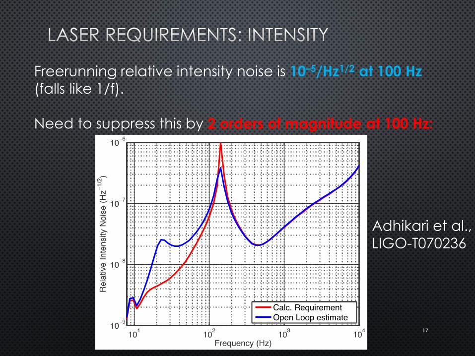
Freerunning relative intensity noise is 10–5/Hz1/2 at 100 Hz
(falls like 1/f).
Need to suppress this by 2 orders of magnitude at 100 Hz:
Adhikari et al.,
LIGO-T070236
17
18
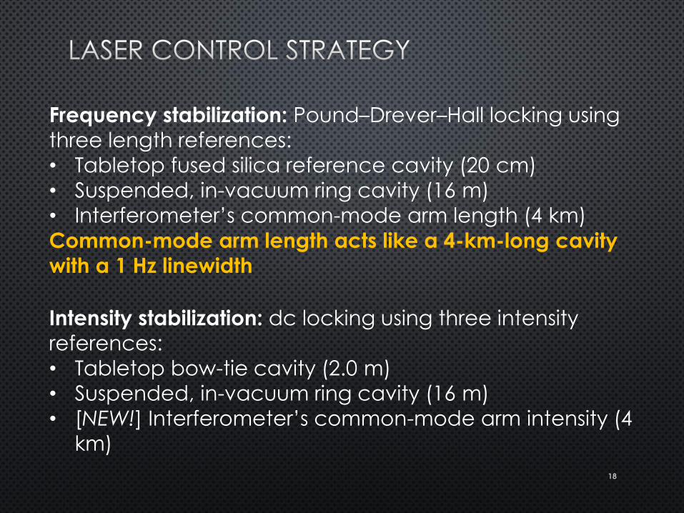
Frequency stabilization: Pound–Drever–Hall locking using
three length references:
• Tabletop fused silica reference cavity (20 cm)
• Suspended, in-vacuum ring cavity (16 m)
• Interferometer’s common-mode arm length (4 km)
Common-mode arm length acts like a 4-km-long cavity
with a 1 Hz linewidth
Intensity stabilization: dc locking using three intensity
references:
• Tabletop bow-tie cavity (2.0 m)
• Suspended, in-vacuum ring cavity (16 m)
• [NEW!] Interferometer’s common-mode arm intensity (4
km)
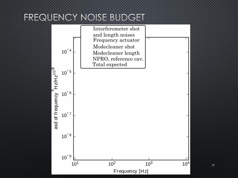
19 101 102 103 104
Frequency [Hz]
10° 9
10° 8
10° 7
10° 6
10° 5
10° 4
asd
of
freq
uen
cy£ H
z/H
z1/2§
Modecleaner shot
Modecleaner length
Interferometer shot
and length noisesFrequency actuator
NPRO, reference cav.Total expected
20
Interferometer optics must be actively controlled in order to maintain
resonance:
• 5 length DOFs
• 20 angular DOFs
In total, there are about 300 servo loops that keep the interferometer
running.
Lowest bandwidth is ~10 mHz (hydraulic compensation of ground
tides)
Highest bandwidth is ~1 MHz (laser noise eater)
21
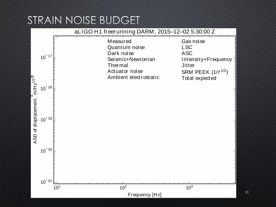
101 102 103
Frequency [Hz]
10° 21
10° 20
10° 19
10° 18
10° 17
AS
Dof
dis
pla
cem
en
t£ m
/Hz
1/2§
aLIGO H1 freer unning DARM, 2015–12–02 5:30:00 Z
MeasuredQuantum noiseDark noiseSeismic+NewtonianTher malActuator noiseAmbient elect rostat ic
Gas noiseLSCASCIntensi ty+FrequencyJit ter
SRM PEEK (1/ f 1/2)Total expected
22
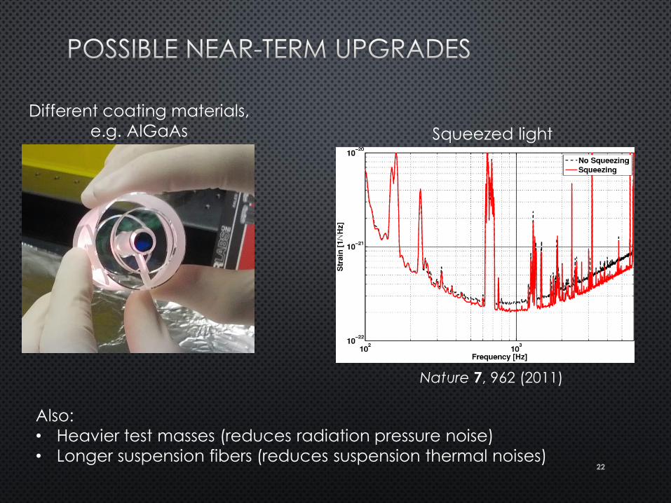
Different coating materials,
e.g. AlGaAs Squeezed light
Also:
• Heavier test masses (reduces radiation pressure noise)
• Longer suspension fibers (reduces suspension thermal noises)
Nature 7, 962 (2011)
23
Use silicon instead of silica
Operate at 120 K (where thermal expansion
coefficient of silicon is zero)
Use 1.5 µm or 2 µm laser
24
Design with shot noise, radiation pressure noise,
and thermal noise in mind
Laser noise rejection is never perfect in an
interferometer, so crush it with servo loops
The common-mode arm length makes a great
reference cavity
Need better coatings, and possibly a different
laser wavelength
25
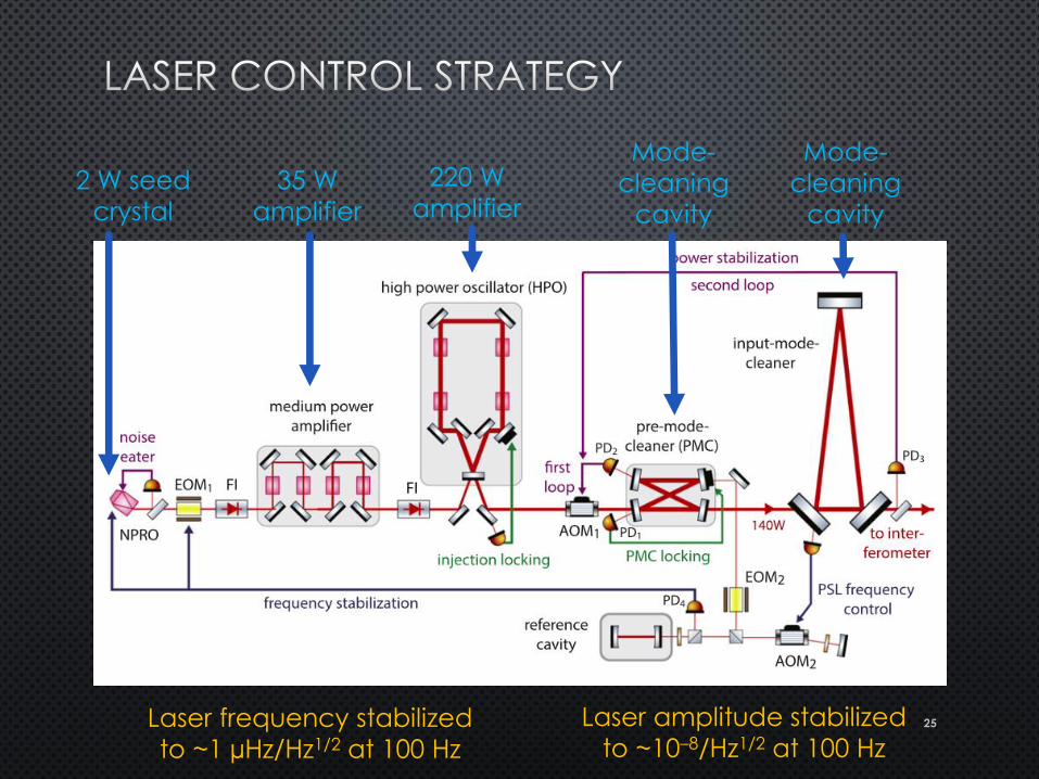
2 W seed
crystal
35 W
amplifier
220 W
amplifier
Mode-
cleaning
cavity
Mode-
cleaning
cavity
Laser frequency stabilized
to ~1 µHz/Hz1/2 at 100 Hz
Laser amplitude stabilized
to ~10–8/Hz1/2 at 100 Hz
26
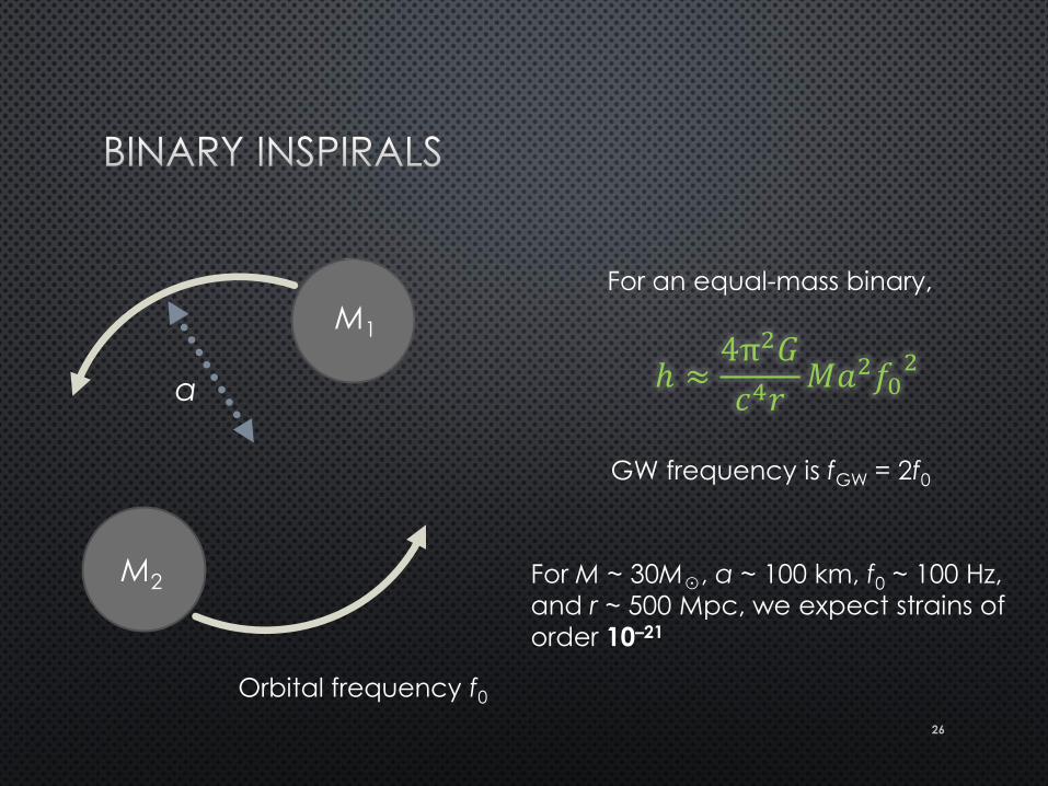
M1
M2
a
For an equal-mass binary,
ℎ ≈4π2𝐺
𝑐4𝑟𝑀𝑎2𝑓0
2
Orbital frequency f0
GW frequency is fGW = 2f0
For M ~ 30M☉, a ~ 100 km, f0 ~ 100 Hz,
and r ~ 500 Mpc, we expect strains of
order 10–21