9000 Plus -710750-Manual Rev C - Corrosion … PLUS CORRATER® INSTRUMENT ... Like all LPR...
29
9000 PLUS CORRATER ® INSTRUMENT Reference Manual Rohrback Cosasco Systems Inc. 11841 East Smith Avenue Santa Fe Springs, CA 90670 Tel: (1) 562-949-0123 Fax: (1) 562-949-3065 E-mail: [email protected] Web Site: www.rohrbackcosasco.com P/N: 710750-Manual Rev C Microcor®, μcor®, Corrdata®, Corrosometer®, Corrater®, Corrotemp® and Aquamate™ are trademarks of Rohrback Cosasco Systems, Inc.
Transcript of 9000 Plus -710750-Manual Rev C - Corrosion … PLUS CORRATER® INSTRUMENT ... Like all LPR...
9000 PLUS
CORRATER® INSTRUMENT Reference Manual
Rohrback Cosasco Systems Inc. 11841 East Smith Avenue Santa Fe Springs, CA 90670
Tel: (1) 562-949-0123 Fax: (1) 562-949-3065 E-mail: [email protected] Web Site: www.rohrbackcosasco.com P/N: 710750-Manual Rev C
Microcor®, μcor®, Corrdata®, Corrosometer®, Corrater®, Corrotemp® and Aquamate™ are trademarks of Rohrback Cosasco Systems, Inc.
© 1991- 2007 Rohrback Cosasco Systems, Inc. All rights reserved. Windows® is a trademark of Microsoft Corporation. No part of this manual may be reproduced or transmitted in any form or by any means, electronic or mechanical, including photocopying and recording, for any purpose, without the express written permission of Rohrback Cosasco Systems, Inc.
i
Table of Contents CHAPTER 1 INTRODUCTION ....................................................................................................1
CHAPTER 2 SPECIFICATIONS .................................................................................................3 OPERATIONAL..............................................................................................................................................3
CHAPTER 3 CORRATER PROBE INSTALLATION ..................................................................5 PROBE CONNECTION ...................................................................................................................................6
CHAPTER 4 OPERATION ..........................................................................................................7 GENERAL ....................................................................................................................................................7 CONFIGURATION ..........................................................................................................................................8 MULTIPLIER LIST..........................................................................................................................................9 INITIAL START UP PARAMETER LIST ..............................................................................................................9 INTERPRETATION OF OPERATING PARAMETERS AND READING .....................................................................10
CHAPTER 5 MAINTENANCE ...................................................................................................11 INTRODUCTION ..........................................................................................................................................11 INSTRUMENT AND PROBE CABLE TEST........................................................................................................11 PROBE REPLACEMENT ...............................................................................................................................11 PROBE CLEANING AND ELECTRODE REPLACEMENT .....................................................................................11 ELECTRODE PRETREATMENT......................................................................................................................13 CORRELATION WITH ELECTRODES AS COUPONS..........................................................................................13
APPENDIX A ..............................................................................................................................15 THEORY OF OPERATION OF CORRATER SYSTEMS....................................................................................15
APPENDIX B ..............................................................................................................................22
APPENDIX C ..............................................................................................................................25
ii 9000 Plus Reference Manual
Figures and Drawings Figure Page Figure 1-1 General View of 9000 Plus Unit................................................................................................1 Figure 3-1 Probe Orientation Relative to Flow...........................................................................................5 Figure 3-2 Probe Orientation at a Tee Fitting ............................................................................................6 Figure 4-1 Front Panel of 9000 Plus ..........................................................................................................7 Figure 4-2 Battery Compartment ...............................................................................................................8 Table 5-1 Corrater Multiplier Factors ......................................................................................................12 Figure A-1 Equivalent Circuit of LPR Probe.............................................................................................16 Figure A-2 Typical LPR Current vs. Time Decay Curve ..........................................................................17 Figure A-3 Operating Range of LPR Instruments - Corrosion Rate vs. Solution Conductivity................18 Figure A-4 Rohrback Cosasco 3-Electrode Probe Configuration ............................................................19 Figure B-1 Conductivity Correction Factor (mpy / µS/cm) .......................................................................22 Figure B-2 Conductivity Correction Factor (mmpy / µS/cm) ....................................................................23 Figure B-3 Conductivity Correction Factor (µmpy / µS/cm) .....................................................................24
1
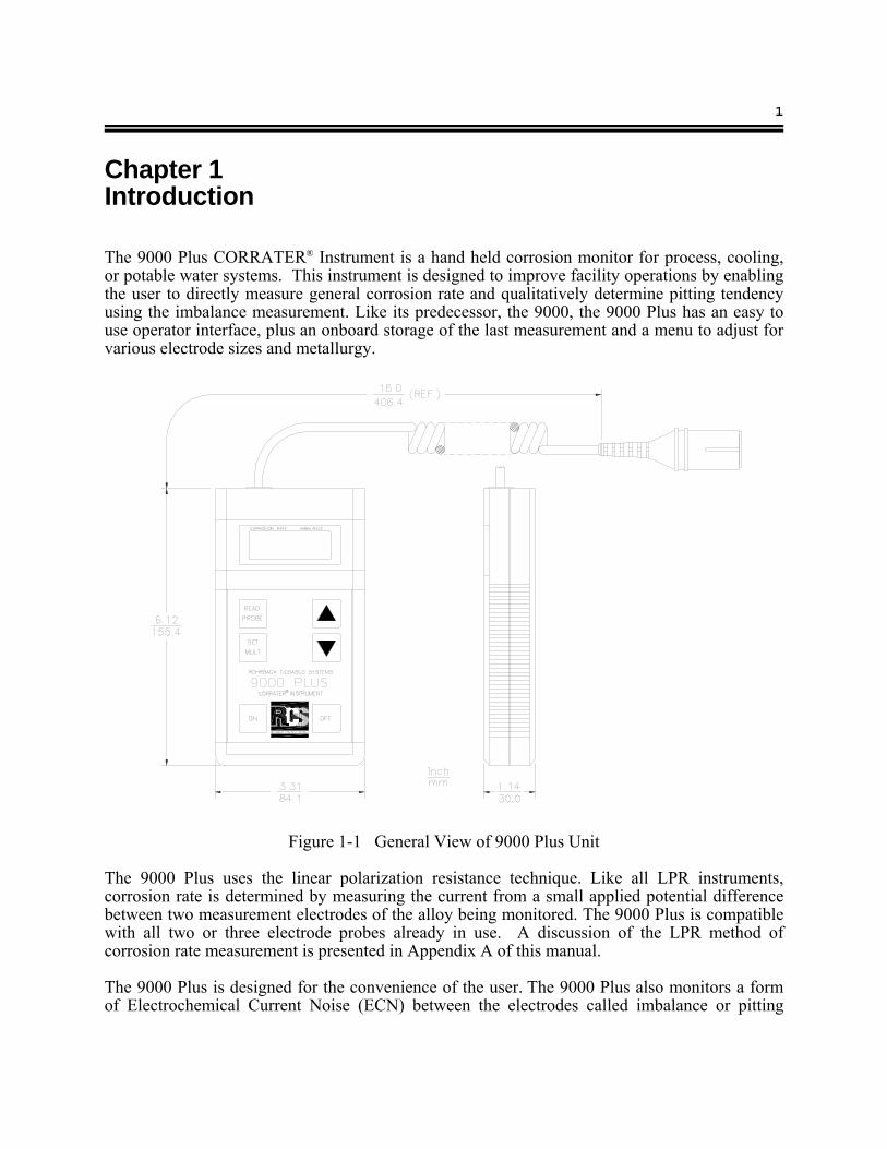
Chapter 1 Introduction The 9000 Plus CORRATER® Instrument is a hand held corrosion monitor for process, cooling, or potable water systems. This instrument is designed to improve facility operations by enabling the user to directly measure general corrosion rate and qualitatively determine pitting tendency using the imbalance measurement. Like its predecessor, the 9000, the 9000 Plus has an easy to use operator interface, plus an onboard storage of the last measurement and a menu to adjust for various electrode sizes and metallurgy.
Figure 1-1 General View of 9000 Plus Unit
The 9000 Plus uses the linear polarization resistance technique. Like all LPR instruments, corrosion rate is determined by measuring the current from a small applied potential difference between two measurement electrodes of the alloy being monitored. The 9000 Plus is compatible with all two or three electrode probes already in use. A discussion of the LPR method of corrosion rate measurement is presented in Appendix A of this manual. The 9000 Plus is designed for the convenience of the user. The 9000 Plus also monitors a form of Electrochemical Current Noise (ECN) between the electrodes called imbalance or pitting
2 9000 Plus Reference Manual
tendency. This is a qualitative and very useful indication of instability in the material surface consistent with pitting or localized corrosion. The operator only needs to perform an initial setup to set the engineering units for corrosion rate, and set the probe multiplier to the size and/or alloy of the electrodes as appropriate. Initial setup is performed via front panel keys while monitoring the liquid crystal display. A description of user definable parameters is given in the operation section of this manual and on a flow chart located on the back of the instrument. In some cases, initial setup will not be required since factory defaults have been set.
3
Chapter 2 Specifications Operational Input:
Single Channel CORRATER® Probe
Corrosion Rate Ranges: Autoranging 0.01 to 200 mpy or 0 to 5.08 mmpy or 0 to 5080 μmpy
Imbalance Ranges: (Pitting Index)
0.01 to 100 pitting units or 0.025 to 250 μA
Probe Compatibility
Two Electrode CORRATER® Probe Three Electrode CORRATER® Probe
Probe Connectors:
6 ft. Coiled Cable with Standard 6 Pin Probe Connector 200 ft. measurement capability
Calibrated Probes:
One point calibrated test probe (P/N: 011000-5) Measurement Cycle Time:
Factory set at 3 minutes, polarization time is 1 minute Multiplier Range:
Menu driven for most common alloys and geometries Instrument Operating Temperature:
32 °F to 122 °F (0 °C to 55 °C) Instrument Storage Temperature:
-4 °F to 131 °F (-20 °C to 55 °C)
4 9000 Plus Reference Manual
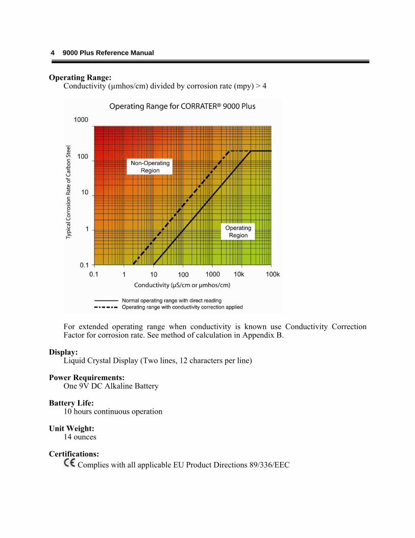
Operating Range: Conductivity (µmhos/cm) divided by corrosion rate (mpy) > 4
For extended operating range when conductivity is known use Conductivity Correction Factor for corrosion rate. See method of calculation in Appendix B.
Display:
Liquid Crystal Display (Two lines, 12 characters per line)
Power Requirements: One 9V DC Alkaline Battery
Battery Life: 10 hours continuous operation
Unit Weight:
14 ounces Certifications:
Complies with all applicable EU Product Directions 89/336/EEC
5
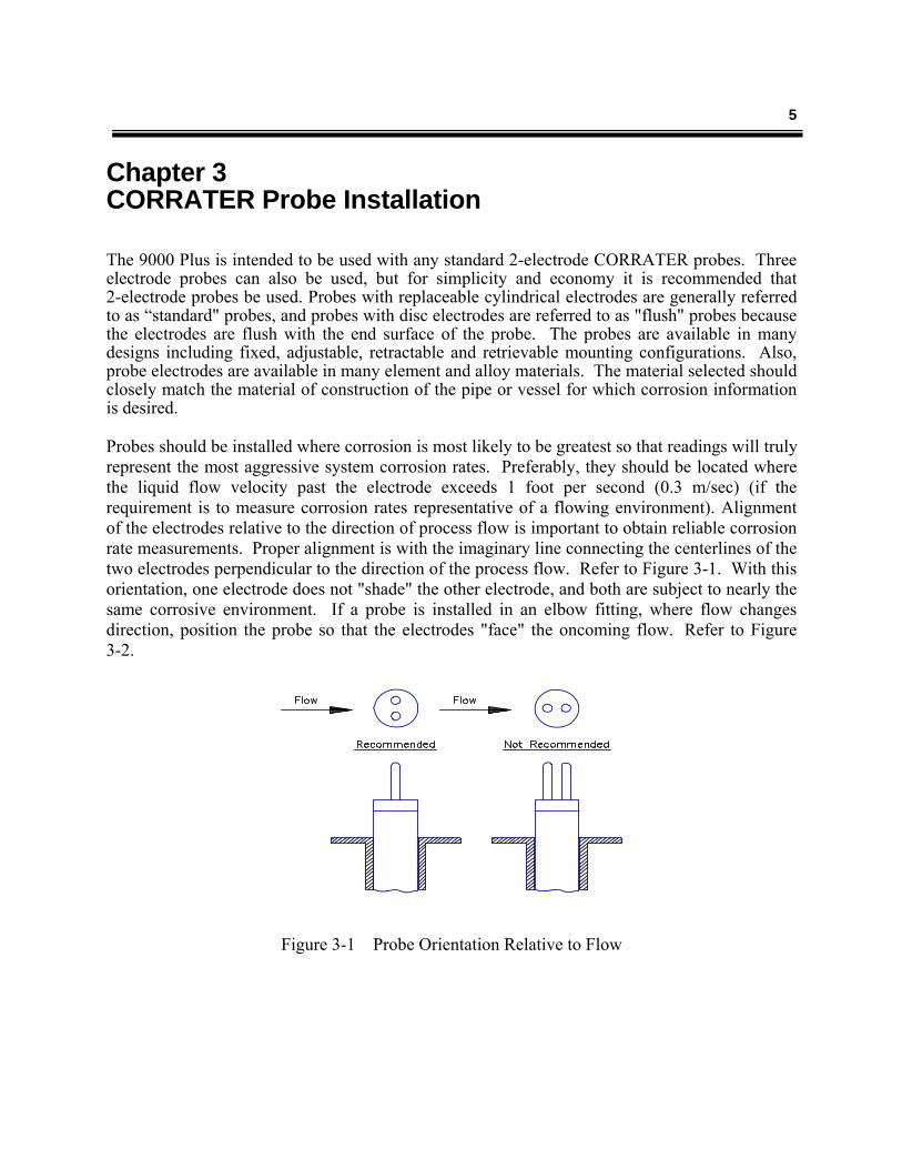
Chapter 3 CORRATER Probe Installation The 9000 Plus is intended to be used with any standard 2-electrode CORRATER probes. Three electrode probes can also be used, but for simplicity and economy it is recommended that 2-electrode probes be used. Probes with replaceable cylindrical electrodes are generally referred to as “standard" probes, and probes with disc electrodes are referred to as "flush" probes because the electrodes are flush with the end surface of the probe. The probes are available in many designs including fixed, adjustable, retractable and retrievable mounting configurations. Also, probe electrodes are available in many element and alloy materials. The material selected should closely match the material of construction of the pipe or vessel for which corrosion information is desired. Probes should be installed where corrosion is most likely to be greatest so that readings will truly represent the most aggressive system corrosion rates. Preferably, they should be located where the liquid flow velocity past the electrode exceeds 1 foot per second (0.3 m/sec) (if the requirement is to measure corrosion rates representative of a flowing environment). Alignment of the electrodes relative to the direction of process flow is important to obtain reliable corrosion rate measurements. Proper alignment is with the imaginary line connecting the centerlines of the two electrodes perpendicular to the direction of the process flow. Refer to Figure 3-1. With this orientation, one electrode does not "shade" the other electrode, and both are subject to nearly the same corrosive environment. If a probe is installed in an elbow fitting, where flow changes direction, position the probe so that the electrodes "face" the oncoming flow. Refer to Figure 3-2.
Figure 3-1 Probe Orientation Relative to Flow
6 9000 Plus Reference Manual
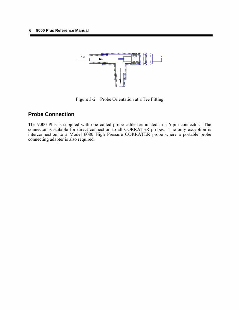
Figure 3-2 Probe Orientation at a Tee Fitting
Probe Connection
The 9000 Plus is supplied with one coiled probe cable terminated in a 6 pin connector. The connector is suitable for direct connection to all CORRATER probes. The only exception is interconnection to a Model 6080 High Pressure CORRATER probe where a portable probe connecting adapter is also required.
7
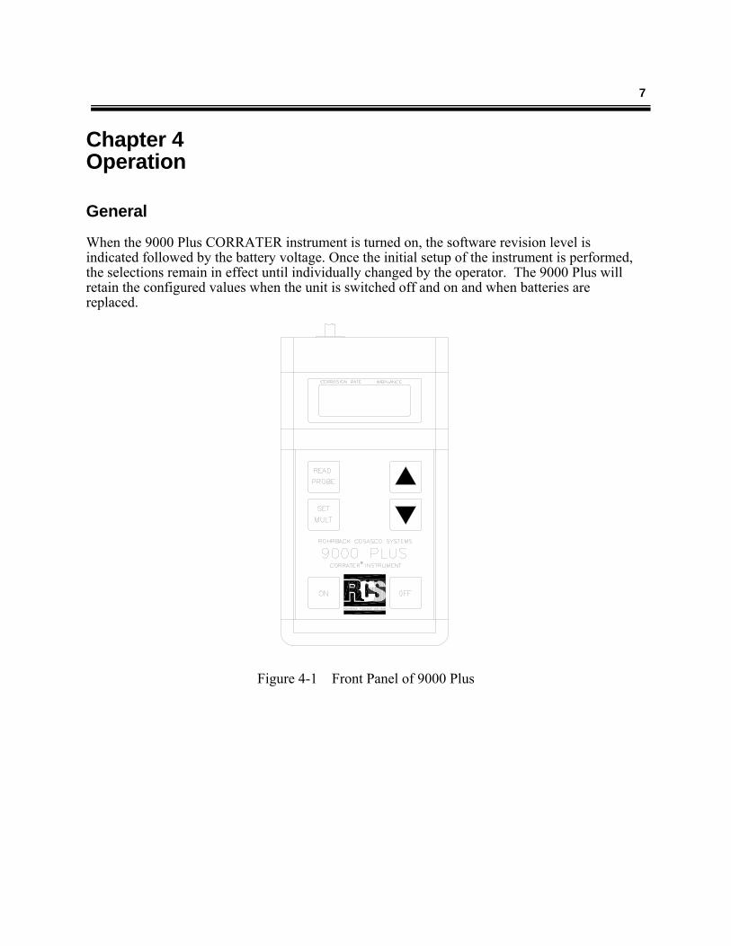
Chapter 4 Operation General When the 9000 Plus CORRATER instrument is turned on, the software revision level is indicated followed by the battery voltage. Once the initial setup of the instrument is performed, the selections remain in effect until individually changed by the operator. The 9000 Plus will retain the configured values when the unit is switched off and on and when batteries are replaced.
Figure 4-1 Front Panel of 9000 Plus
8 9000 Plus Reference Manual
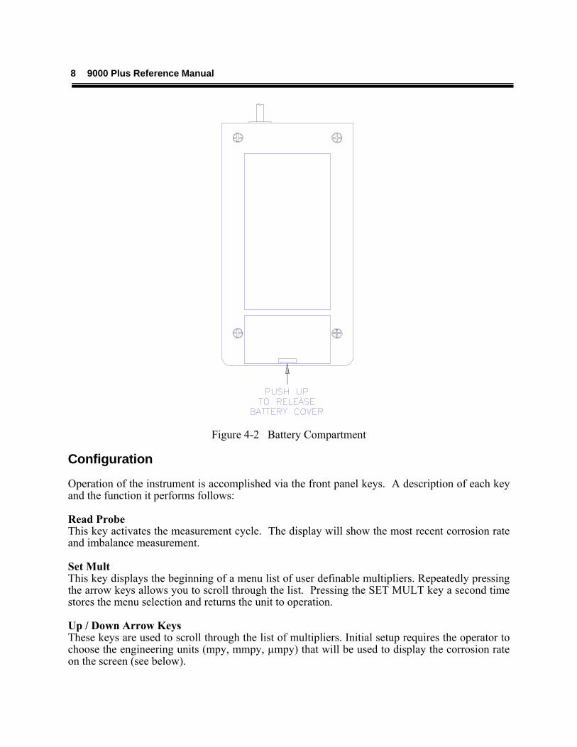
Figure 4-2 Battery Compartment
Configuration
Operation of the instrument is accomplished via the front panel keys. A description of each key and the function it performs follows: Read Probe This key activates the measurement cycle. The display will show the most recent corrosion rate and imbalance measurement. Set Mult This key displays the beginning of a menu list of user definable multipliers. Repeatedly pressing the arrow keys allows you to scroll through the list. Pressing the SET MULT key a second time stores the menu selection and returns the unit to operation. Up / Down Arrow Keys These keys are used to scroll through the list of multipliers. Initial setup requires the operator to choose the engineering units (mpy, mmpy, µmpy) that will be used to display the corrosion rate on the screen (see below).
9
Multiplier List PROBE MULTIPLIER The alloy correction and geometry multipliers are selectable from the Set Mult menu. Use the arrow keys to scroll through the following options and press the Set Mult key when the correct choice is displayed.
Mild Steel Admiralty Brass Copper 304 Stainless Steel 316 Stainless Steel 90/10 Copper/Nickel 70/30 Copper/Nickel Zinc Lead 1100 Aluminum 2024 Aluminum Flush (Mild Steel) 9 cm Area (Mild Steel)
If it is necessary to check the current setting of the multiplier, press the Set Mult key, and the current setting is displayed. If it is the desired selection, press Set Mult again to return to normal operation. If a measurement is taken with an incorrect multiplier, simply change the multiplier to the desired option and the measurement on the display will be changed to the correct value. Conversely, when you change the multiplier for a new probe, the displayed measurement will be inaccurate until a new measurement cycle is completed. The factory default setting is at Mild Steel. Initial Start Up Parameter List ENGINEERING UNITS The selectable units are mils per year (mpy), millimeters per year (mmpy) or micrometers per year (µmpy). The factory default is set at mpy. SETTING ENGINEERING UNITS The engineering unit menu is accessed by holding down both arrow keys simultaneously when the instrument is off and then applying power to the unit by pressing the on key. The 9000 Plus will display the current setting for engineering units. Use the arrow keys to scroll through the three options. When the desired option is displayed, press the Set Mult key to save your selection and initiate normal operation.
10 9000 Plus Reference Manual
Interpretation of Operating Parameters and Reading Imbalance Readings: Imbalance is often referred to as "pitting tendency". It is actually a sample of Electrochemical Current Noise (ECN) between the two electrodes when the electrodes are connected to a zero-impedance ammeter effectively measuring the short circuit current. The 9000 Plus measures this current and displays the results in units of 0.5 µA per square centimeter of surface area of each electrode (with mpy units and at a multiplier of 1.00). Regular electrodes are 5.0 square centimeters and therefore one imbalance or pitting unit is 2.5 µA of current (with mpy units and at a multiplier of 1.00). Scaling of this reading is modified by the probe multiplier and metric unit conversion. The purpose for this scaling is to make the imbalance reading meaningful when compared to the corrosion rate reading. It has been found empirically that when the imbalance reading is less than the corrosion rate reading or close to zero, corrosion is general corrosion with insignificant pitting. If the imbalance becomes more erratic and similar to or greater than the corrosion rate value, this is indicative of increased pitting. If the imbalance is up to ten times greater than the corrosion rate or very erratic this is indicative of a significant pitting which should be verified by visual inspection of the probe electrodes. Imbalance can be caused by several factors: 1. Severe pitting. Pitting is generally irregular and non-uniform, consequently the greater this
irregularity or non-uniformity, the greater is the probability of imbalance between the two electrodes. Pitting is generally accompanied by an increase in imbalance and also greater irregularity and fluctuation of the reading.
. 2. Improper or inadequate inhibitor film formation. Where filming inhibitors are used and are
not established due to inadequate flow or quantity of inhibitor, imbalance is greater and shows greater fluctuation. This will often anticipate an increasing corrosion rate with reducing inhibitor film.
3. Differential scaling or fouling of the electrode. 4. Damage to an electrode or a loosened electrode.
NOTE: Imbalance readings will typically increase when corrosion rate values increase. There should be concern for pitting when the imbalance increases significantly without a similar increase in corrosion rate.
11
Chapter 5 Maintenance Introduction
Routine maintenance of 9000 Plus is not required except for battery replacement. Probes, however, should be inspected at intervals and electrodes replaced when required. If a problem is suspected with the 9000 Plus instrument, the following tests can be performed to verify proper operation of the instrument. Instrument and Probe Cable Test The instrument is shipped from the factory with a test probe, RCS part number 011000-5. The test probe will simulate a corrosion rate of 5 mpy (±1) at a multiplier of 1.0. If acceptable readings are performed on test probes, then problems are likely to be caused by the process itself or the probe in service. A fouling problem, for example, can bridge the electrodes and yield readings outside the normal measurement range of the instrument.
NOTE: Be sure to set the multiplier parameter to mild steel when measuring test probes and to return it to its previous setting when completed.
Probe Replacement Probe replacement is not required except due to damage or deterioration. Replace the probe if there is physical damage or a low resistance (less than 1 Meg-Ohm) between the electrodes when disconnected from the electronics. Probe Cleaning and Electrode Replacement As supplied from the factory, CORRATER electrodes have grit blasted surfaces and require no further cleaning before they are used. Probes should be checked at intervals particularly for conductive debris "shorting" out the electrodes which may be indicated by a very high corrosion rate reading. They should be cleaned and polished to a dull shine with an emery cloth. After cleaning, the electrodes should be thoroughly degreased in a suitable solvent, and handled with a clean cloth or paper towel to prevent contamination. The important factor is that the electrodes should be REPRESENTATIVE of the conditions to be monitored. New electrodes may be more responsive to changes in the corrosivity of the fluid. Electrodes which have been in use for sometime will be more representative of corrosion rates of the more aged plant/system material, which will have some film build-up.
12 9000 Plus Reference Manual
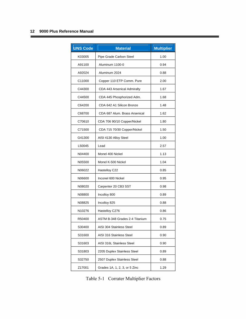
UNS Code Material Multiplier
K03005 Pipe Grade Carbon Steel 1.00
A91100 Aluminum 1100-0 0.94
A92024 Aluminum 2024 0.88
C11000 Copper 110 ETP Comm. Pure 2.00
C44300 CDA 443 Arsenical Admiralty 1.67
C44500 CDA 445 Phosphorized Adm. 1.68
C64200 CDA 642 A1 Silicon Bronze 1.48
C68700 CDA 687 Alum. Brass Arsenical 1.62
C70610 CDA 706 90/10 Copper/Nickel 1.80
C71500 CDA 715 70/30 Copper/Nickel 1.50
G41300 AISI 4130 Alloy Steel 1.00
L50045 Lead 2.57
N04400 Monel 400 Nickel 1.13
N05500 Monel K-500 Nickel 1.04
N06022 Hastelloy C22 0.85
N06600 Inconel 600 Nickel 0.95
N08020 Carpenter 20 CB3 SST 0.98
N08800 Incolloy 800 0.89
N08825 Incolloy 825 0.88
N10276 Hastelloy C276 0.86
R50400 ASTM B-348 Grades 2-4 Titanium 0.75
S30400 AISI 304 Stainless Steel 0.89
S31600 AISI 316 Stainless Steel 0.90
S31603 AISI 316L Stainless Steel 0.90
S31803 2205 Duplex Stainless Steel 0.89
S32750 2507 Duplex Stainless Steel 0.88
Z17001 Grades 1A, 1, 2, 3, or 5 Zinc 1.29
Table 5-1 Corrater Multiplier Factors
13
NOTE: These factors are stored in the memory and are accessed when setting the MULTIPLIER value as described in Section 4. Metallurgy Values are based upon use of CORRATER electrodes which have surface areas of 5cm2 for "standard" probes and 0.5 cm2 for "flush" probes. When metallurgy is used that is not preprogrammed in the 9000 Plus, select mild steel and manually multiply the factor below.
Electrodes should be replaced when the diameter is reduced 1/32 inch (0.794 mm) or more. CORRATER electrodes are nominally 3/16 inch (4.76 mm) diameter and 1 1/4 inch (31.75 mm) in length when new. As corrosion occurs on the electrodes, their diameter decreases and begins to significantly affect the accuracy of the corrosion readings. Do not use pliers when installing new or cleaned electrodes on a standard probe body. They should be screwed onto each mounting stud only "finger-tight", slightly compressing the rubber O-rings at the base of the stud. Handle the electrodes with a clean cloth or paper towel to avoid depositing any contaminating oily film. In the event of contamination, a suitable degreaser can be used to clean the electrodes. Electrode Pretreatment Pretreatment of the electrodes may be done is some instances, but is only recommended if the same type of treatment is used on the plant/system whenever new material is installed. Generally, a full strength sample of the treatment chemical is used. The new electrodes are carefully placed into the solution for a 6-12 hour period and then threaded onto the probe and placed into service. Some systems employ an initial, high-level treatment procedure before the inhibitor rate is reduced to a maintenance level. The treatment should be selected relative to the probe electrodes being used. If the electrodes are installed without pretreatment, the corrosion rate indicated will be that of which would occur on new material put in the system. This may typically take a few hours to a few days to decrease to the normal on-going value. Pretreatment may artificially protect the material so that it is unrepresentative of any new material that may be put in the system. Correlation with Electrodes as Coupons Weigh the electrodes in the same manner as a coupon would be weighed on a balance scale graduated to 0.0001 gram before placing them in service. The coupon should be placed into service at the same time. After a 30, 60 or 90 day period, remove, clean and analyze them in the same manner. The readings from the instrument integrated over a period of time and the data from the electrodes and coupons should correlate.

14 9000 Plus Reference Manual
15
Appendix A
Theory of Operation of CORRATER Systems CORRATER systems measure the instantaneous corrosion rate of a metal in a conductive fluid using the linear polarization resistance ("LPR") measurement technique. Corrosion is an electrochemical process in which electrons are transferred between anodic and cathodic areas on the corroding metal resulting in oxidation (corrosion) of the metal at the anode and reduction of cations in the fluid at the cathode. Sterns and Geary originally demonstrated that the application of a small polarizing potential difference (ΔE) from the corrosion potential (Ecorr) of a corroding electrode resulted in a measured current density (imeas) which is related to the corrosion current density (icorr) by equation (1):
ΔE = ba bc (1) imeas (2.303 icorr) (ba + bc)
where: ba = Anodic Tafel Slope bc = Cathodic Tafel Slope
Since the Tafel coefficients are more or less constant for a given metal/fluid combination, imeas is proportional to icorr which is proportional to the corrosion rate. Equation (1) and the entire LPR technique are only valid when the polarizing potential difference is very low (typically up to 20 mV). In this region the curves are linear, hence the term LPR. Inspection of Equation (1) shows that the result is a resistance, the Polarization Resistance, Rp. While strictly speaking, there are both anodic and cathodic Rp values, which can differ, they are usually assumed to be equal. The resistance to current flow between anode and cathode on the LPR probe is the sum of both polarization resistance values and the resistance of the solution between the electrodes (RS) as shown in Equation (2):
E = imeas (2Rp + RS) (2) where: Rs = Resistance of the solution
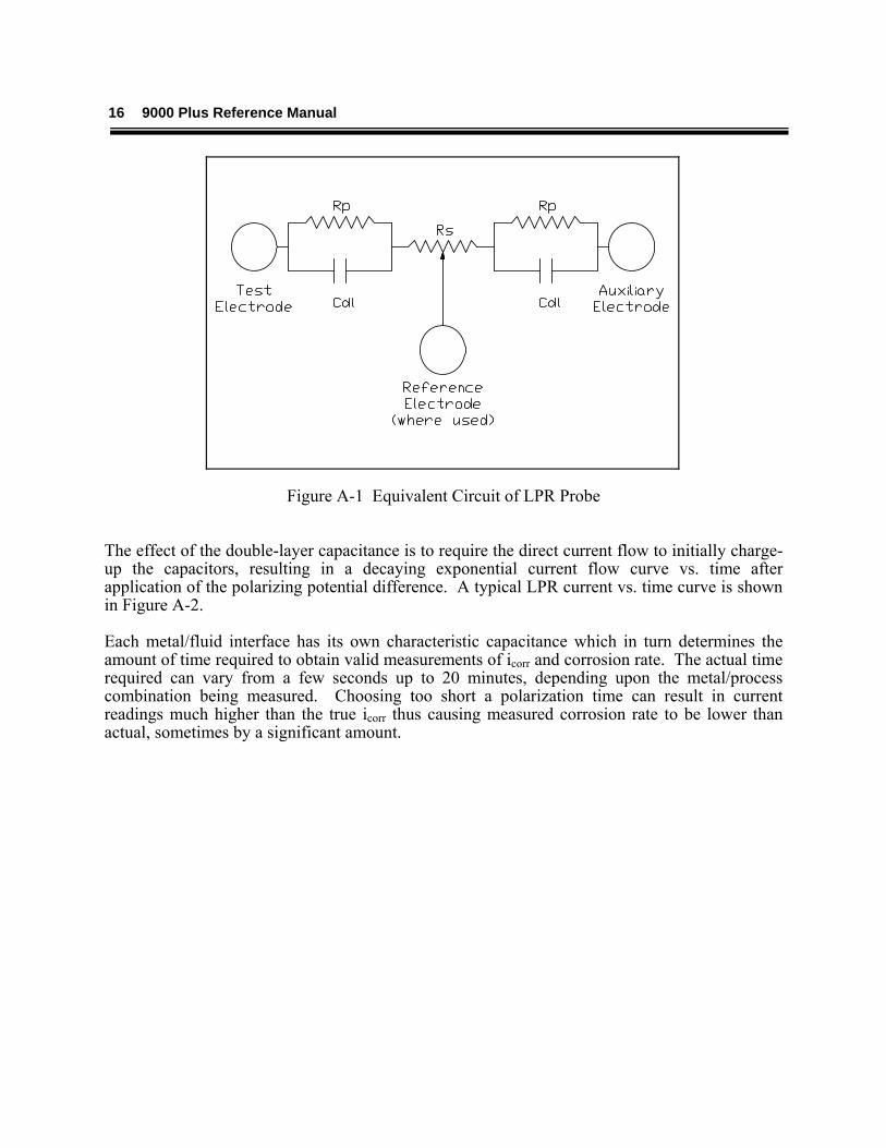
between the two electrodes From Equations (1) and (2), obtaining results from the LPR technique would seem to require only instantaneous readings of resistance. In practice, however, the determination of polarization resistance is complicated by a capacitance effect at the metal-fluid interface (double-layer capacitance (Cdl)). Figure A-1 is an equivalent electrical circuit of the corrosion cell formed by the measuring electrodes and the fluid, showing the importance of RS and double-layer capacitance effects.
16 9000 Plus Reference Manual
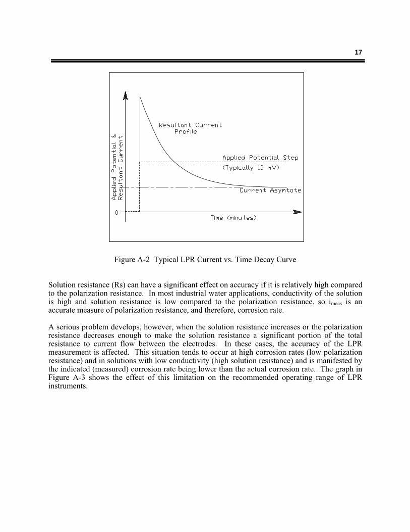
Figure A-1 Equivalent Circuit of LPR Probe The effect of the double-layer capacitance is to require the direct current flow to initially charge-up the capacitors, resulting in a decaying exponential current flow curve vs. time after application of the polarizing potential difference. A typical LPR current vs. time curve is shown in Figure A-2. Each metal/fluid interface has its own characteristic capacitance which in turn determines the amount of time required to obtain valid measurements of icorr and corrosion rate. The actual time required can vary from a few seconds up to 20 minutes, depending upon the metal/process combination being measured. Choosing too short a polarization time can result in current readings much higher than the true icorr thus causing measured corrosion rate to be lower than actual, sometimes by a significant amount.
17
Figure A-2 Typical LPR Current vs. Time Decay Curve
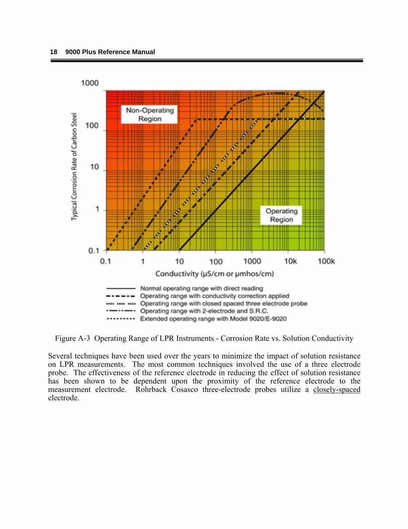
Solution resistance (Rs) can have a significant effect on accuracy if it is relatively high compared to the polarization resistance. In most industrial water applications, conductivity of the solution is high and solution resistance is low compared to the polarization resistance, so imeas is an accurate measure of polarization resistance, and therefore, corrosion rate. A serious problem develops, however, when the solution resistance increases or the polarization resistance decreases enough to make the solution resistance a significant portion of the total resistance to current flow between the electrodes. In these cases, the accuracy of the LPR measurement is affected. This situation tends to occur at high corrosion rates (low polarization resistance) and in solutions with low conductivity (high solution resistance) and is manifested by the indicated (measured) corrosion rate being lower than the actual corrosion rate. The graph in Figure A-3 shows the effect of this limitation on the recommended operating range of LPR instruments.
18 9000 Plus Reference Manual
Figure A-3 Operating Range of LPR Instruments - Corrosion Rate vs. Solution Conductivity Several techniques have been used over the years to minimize the impact of solution resistance on LPR measurements. The most common techniques involved the use of a three electrode probe. The effectiveness of the reference electrode in reducing the effect of solution resistance has been shown to be dependent upon the proximity of the reference electrode to the measurement electrode. Rohrback Cosasco three-electrode probes utilize a closely-spaced electrode.
19
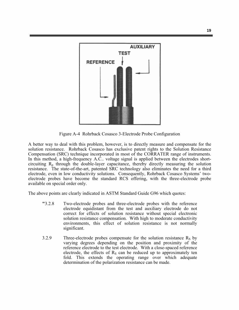
Figure A-4 Rohrback Cosasco 3-Electrode Probe Configuration A better way to deal with this problem, however, is to directly measure and compensate for the solution resistance. Rohrback Cosasco has exclusive patent rights to the Solution Resistance Compensation (SRC) technique incorporated in most of the CORRATER range of instruments. In this method, a high-frequency A.C.. voltage signal is applied between the electrodes short-circuiting Rp through the double-layer capacitance, thereby directly measuring the solution resistance. The state-of-the-art, patented SRC technology also eliminates the need for a third electrode, even in low conductivity solutions. Consequently, Rohrback Cosasco Systems’ two-electrode probes have become the standard RCS offering, with the three-electrode probe available on special order only. The above points are clearly indicated in ASTM Standard Guide G96 which quotes:
"3.2.8 Two-electrode probes and three-electrode probes with the reference electrode equidistant from the test and auxiliary electrode do not correct for effects of solution resistance without special electronic solution resistance compensation. With high to moderate conductivity environments, this effect of solution resistance is not normally significant.
3.2.9 Three-electrode probes compensate for the solution resistance RS by
varying degrees depending on the position and proximity of the reference electrode to the test electrode. With a close-spaced reference electrode, the effects of RS can be reduced up to approximately ten fold. This extends the operating range over which adequate determination of the polarization resistance can be made.
20 9000 Plus Reference Manual
3.2.10 A two-electrode probe with electrochemical impedance measurement technique at high frequency short circuits the double-layer capacitance, Cdl, so that a measurement of solution resistance RS can be made for application as a correction. This also extends the operating range over which adequate determination of polarization resistance can be made."
Imbalance (or Pitting/Index) Metal surfaces, no matter how uniform they may appear, have numerous microscopic imperfections. Metals such as iron alloys are crystalline in structure but surface imperfections such as small intergranular cavities tend to grow, especially in liquids that have large concentrations of dissolved oxygen. The corrosion processes (iron oxidation) for iron alloys can be described by the following anodic reaction:
Fe Fe+2 + 2e
this, in an oxygen rich environment, can be “driven” by the following cathodic reaction:
O2 + 2H2O + 4e 4 OH
When large amounts of oxygen are available at a portion of a metal surface, oxygen not only maintains this cathodic reaction, but it promotes the reaction. At other locations on the metal surface where oxygen is less available, the anodic reaction proceeds to balance the cathodic reaction. A small intergranular cavity would represent an excellent site for the anodic reaction to take place because there is less available oxygen. In the case of an iron alloy, the reaction causes the rapid localized conversion of iron atoms to ferrous ions since a small anodic area can be supported by the larger cathodic area. As this iron oxidation proceeds, the small cavity grows, which in turn exposes a larger iron surface that is essentially void of oxygen causing it to be a very active anode. This process which has the natural tendency to accelerate describes the growth of a corrosion pit. Since susceptible pitting sites tend to be randomly distributed and generally are not too numerous on a metal surface, there is a high probability that on two seemingly identical metal electrodes, one of the electrodes will have a greater number of susceptible pitting sites than the other electrode. If these two electrodes are the electrodes of a two-electrode CORRATER probe and they are submersed in a conductive solution which tends to promote pitting, one electrode will exhibit a more positive corrosion potential (Ecorr) than the other. The polarity of the open-circuit potential difference (Eoc) will indicate which electrode has the greater pitting tendency. That electrode will be the more negative of the two. If these electrodes are electrically connected through a zero-resistance ammeter (ZRA), the measured short-circuit current is a measure of the pitting tendency of the electrode material in the aqueous environment. This is the measurement technique that it is utilized in CORRATER
21
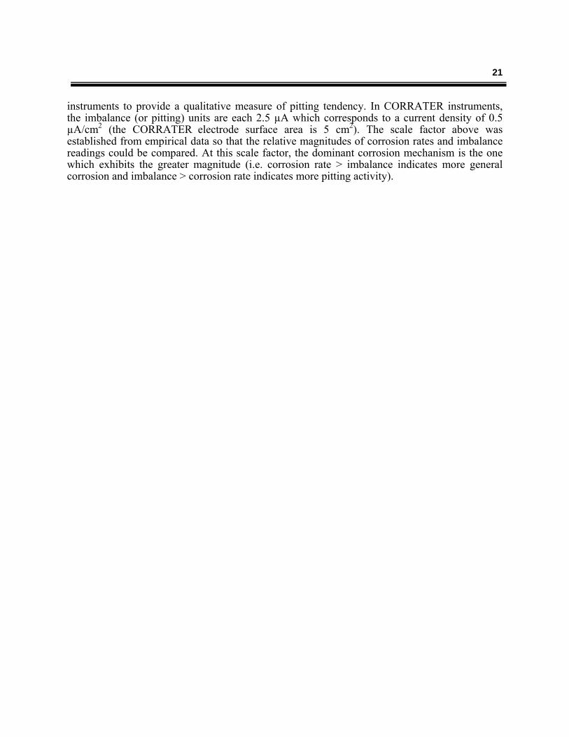
instruments to provide a qualitative measure of pitting tendency. In CORRATER instruments, the imbalance (or pitting) units are each 2.5 µA which corresponds to a current density of 0.5 µA/cm2 (the CORRATER electrode surface area is 5 cm2). The scale factor above was established from empirical data so that the relative magnitudes of corrosion rates and imbalance readings could be compared. At this scale factor, the dominant corrosion mechanism is the one which exhibits the greater magnitude (i.e. corrosion rate > imbalance indicates more general corrosion and imbalance > corrosion rate indicates more pitting activity).
22 9000 Plus Reference Manual
Appendix B
Figure B-1 Conductivity Correction Factor (mpy / µS/cm)
23
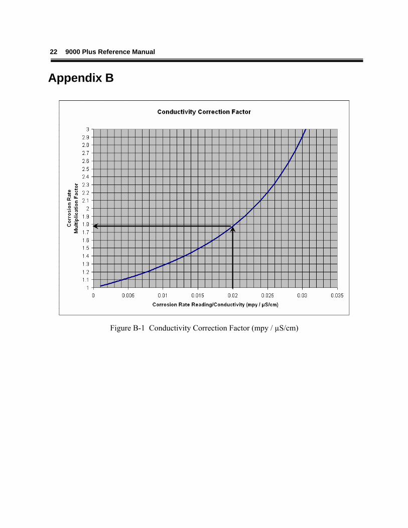
Figure B-2 Conductivity Correction Factor (mmpy / µS/cm)
24 9000 Plus Reference Manual
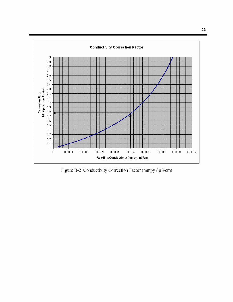
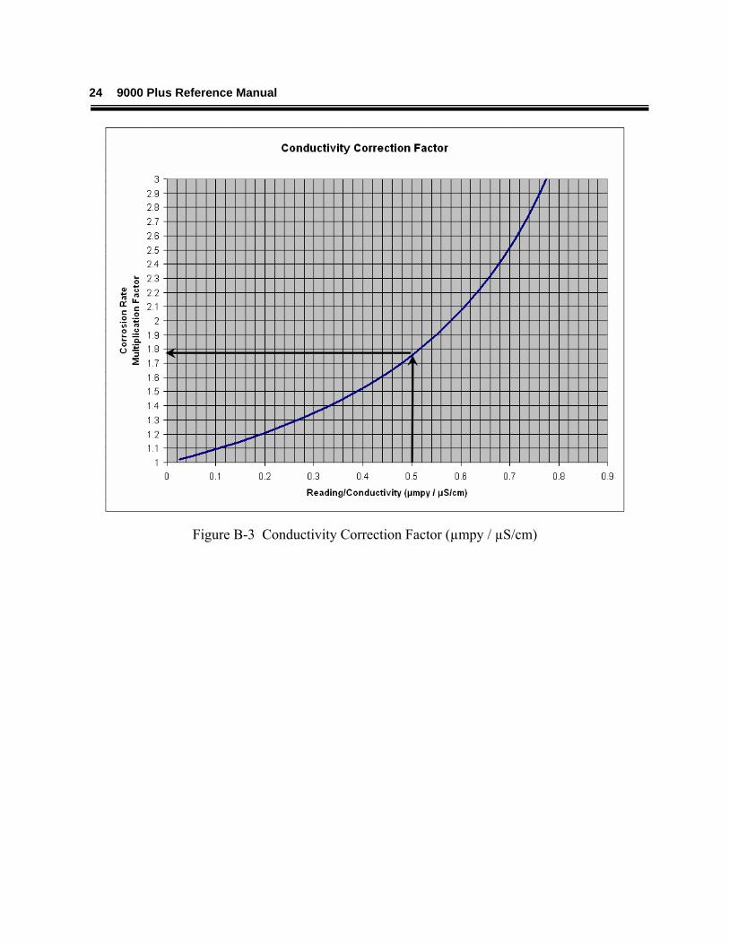
Figure B-3 Conductivity Correction Factor (µmpy / µS/cm)
25
Appendix C
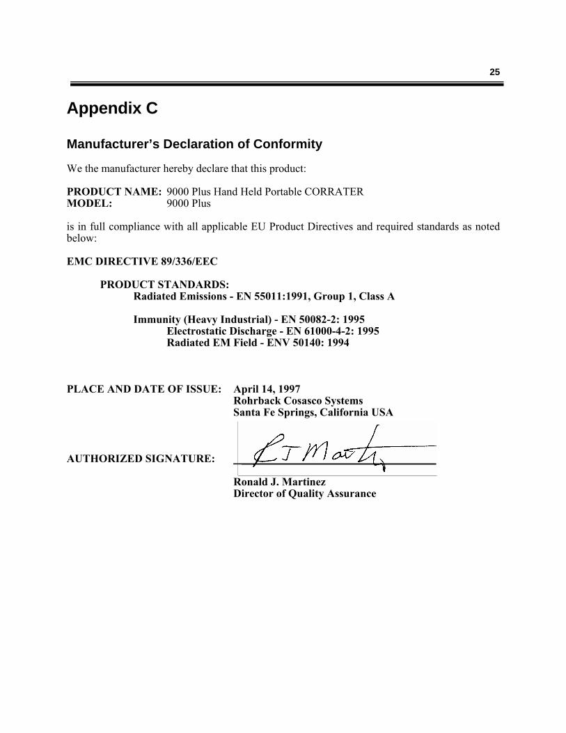
Manufacturer’s Declaration of Conformity We the manufacturer hereby declare that this product: PRODUCT NAME: 9000 Plus Hand Held Portable CORRATER MODEL: 9000 Plus is in full compliance with all applicable EU Product Directives and required standards as noted below: EMC DIRECTIVE 89/336/EEC
PRODUCT STANDARDS: Radiated Emissions - EN 55011:1991, Group 1, Class A
Immunity (Heavy Industrial) - EN 50082-2: 1995
Electrostatic Discharge - EN 61000-4-2: 1995 Radiated EM Field - ENV 50140: 1994
PLACE AND DATE OF ISSUE: April 14, 1997
Rohrback Cosasco Systems Santa Fe Springs, California USA
AUTHORIZED SIGNATURE: ___________________________________
Ronald J. Martinez Director of Quality Assurance