80m and 40m Dual-band Vertical Antenna KV2 - R … · 80m and 40m Dual-band Vertical Antenna KV2...
3
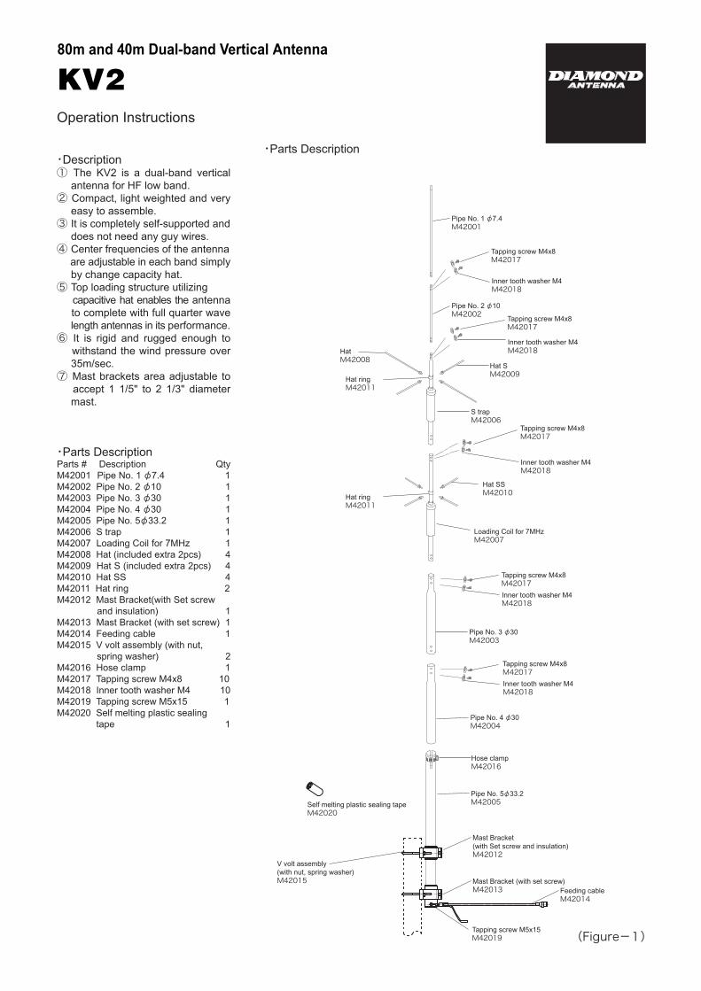
80m and 40m Dual-band Vertical Antenna KV2 ・ Parts Description Operation Instructions (Figure-1) Pipe No. 1 φ7.4 M42001 Tapping screw M4x8 M42017 Inner tooth washer M4 M42018 S trap M42006 Inner tooth washer M4 M42018 Tapping screw M4x8 M42017 Pipe No. 2 φ10 M42002 Hat M42008 Hat ring M42011 ・ Description ① The KV2 is a dual-band vertical antenna for HF low band. ② Compact, light weighted and very easy to assemble. ③ It is completely self-supported and does not need any guy wires. ④ Center frequencies of the antenna are adjustable in each band simply by change capacity hat. ⑤ Top loading structure utilizing capacitive hat enables the antenna to complete with full quarter wave length antennas in its performance. ⑥ It is rigid and rugged enough to withstand the wind pressure over 35m/sec. ⑦ Mast brackets area adjustable to accept 1 1/5" to 2 1/3" diameter mast. ・ Parts Description Parts # Description Qty M42001 Pipe No. 1 φ7.4 1 M42002 Pipe No. 2 φ10 1 M42003 Pipe No. 3 φ30 1 M42004 Pipe No. 4 φ30 1 M42005 Pipe No. 5 φ33.2 1 M42006 S trap 1 M42007 Loading Coil for 7MHz 1 M42008 Hat (included extra 2pcs) 4 M42009 Hat S (included extra 2pcs) 4 M42010 Hat SS 4 M42011 Hat ring 2 M42012 Mast Bracket(with Set screw and insulation) 1 M42013 Mast Bracket (with set screw) 1 M42014 Feeding cable 1 M42015 V volt assembly (with nut, spring washer) 2 M42016 Hose clamp 1 M42017 Tapping screw M4x8 10 M42018 Inner tooth washer M4 10 M42019 Tapping screw M5x15 1 M42020 Self melting plastic sealing tape 1 Inner tooth washer M4 M42018 Tapping screw M4x8 M42017 Hat SS M42010 Hat ring M42011 Loading Coil for 7MHz M42007 Pipe No. 3 φ30 M42003 Pipe No. 4 φ30 M42004 Inner tooth washer M4 M42018 Tapping screw M4x8 M42017 Hose clamp M42016 Pipe No. 5φ33.2 M42005 Mast Bracket (with Set screw and insulation) M42012 Mast Bracket (with set screw) M42013 V volt assembly (with nut, spring washer) M42015 Tapping screw M5x15 M42019 Self melting plastic sealing tape M42020 Feeding cable M42014 Hat S M42009 Inner tooth washer M4 M42018 Tapping screw M4x8 M42017
Transcript of 80m and 40m Dual-band Vertical Antenna KV2 - R … · 80m and 40m Dual-band Vertical Antenna KV2...
80m and 40m Dual-band Vertical Antenna
KV2
・Parts Description
Operation Instructions
(Figure-1)
Pipe No. 1 φ7.4 M42001
Tapping screw M4x8M42017
Inner tooth washer M4M42018
S trapM42006
Inner tooth washer M4M42018
Tapping screw M4x8M42017
Pipe No. 2 φ10M42002
Hat M42008
Hat ring M42011
・Description① The KV2 is a dual-band vertical antenna for HF low band.② Compact, light weighted and very easy to assemble.③ It is completely self-supported and does not need any guy wires.④ Center frequencies of the antenna are adjustable in each band simply by change capacity hat.⑤ Top loading structure utilizing capacitive hat enables the antenna to complete with full quarter wave length antennas in its performance.⑥ It is rigid and rugged enough to withstand the wind pressure over 35m/sec.⑦ Mast brackets area adjustable to accept 1 1/5" to 2 1/3" diameter mast.
・Parts DescriptionParts # Description QtyM42001 Pipe No. 1 φ7.4 1M42002 Pipe No. 2 φ10 1M42003 Pipe No. 3 φ30 1M42004 Pipe No. 4 φ30 1M42005 Pipe No. 5φ33.2 1M42006 S trap 1M42007 Loading Coil for 7MHz 1M42008 Hat (included extra 2pcs) 4M42009 Hat S (included extra 2pcs) 4M42010 Hat SS 4M42011 Hat ring 2M42012 Mast Bracket(with Set screw and insulation) 1M42013 Mast Bracket (with set screw) 1M42014 Feeding cable 1M42015 V volt assembly (with nut, spring washer) 2M42016 Hose clamp 1M42017 Tapping screw M4x8 10M42018 Inner tooth washer M4 10M42019 Tapping screw M5x15 1M42020 Self melting plastic sealing tape 1
Inner tooth washer M4M42018
Tapping screw M4x8M42017
Hat SSM42010
Hat ringM42011
Loading Coil for 7MHzM42007
Pipe No. 3 φ30M42003
Pipe No. 4 φ30M42004
Inner tooth washer M4M42018
Tapping screw M4x8M42017
Hose clampM42016
Pipe No. 5φ33.2M42005
Mast Bracket(with Set screw and insulation)M42012
Mast Bracket (with set screw)M42013
V volt assembly(with nut, spring washer)M42015
Tapping screw M5x15M42019
Self melting plastic sealing tapeM42020
Feeding cableM42014
Hat SM42009
Inner tooth washer M4M42018
Tapping screw M4x8M42017
Tranceiver VSWRmeter
KV2
Hose clamp
Pipe No.5 φ33.2
Mast Bracket(with Set screw and insulation)
25~30cmMast
V volt assembly (with nut,spring washer)
Feeding cableEarth cable
EarthEarth
Mast Bracket (with set screw)
MJ-connector
Tapping screwM5x15
(Figure-2)
-Note-----------------------------
<<Installing the antenna>>① Don't install on a rainy or windy day since it is dangerous.② If the KV2 is located on the roof of a house or top of a building, look around the roof to see if there are any obstacles such as an electronic wire or TV antenna. The KV2 has to be located as far away as possible from those things to obtain its maximum performance. Installing the antenna too close to the building wall may cause bad effect for electrical characteristics of the antenna.③ Don't install the antenna where is easily reachable by people.④ Install the antenna firmly not to fall down due to the strong wind. Even if falling down the antenna, locate the antenna at the safe place where people and building are not inflicted injures.
<<Before transmitting>>①Transmit after confirming if the antenna works normally by an SWR meter. If VSWR is less than 1.5, it is no problem. If VSWR is higher, stop transmitting and check if the parts of the antenna and coaxial cable are connected. If there are tall buildings or obstacles or the distance between the antenna and the ground is short, VSWR may not be lowered.※Diamond Antenna SWR/POWER meter is an insertion type being connected between a transmitter and an antenna. Transmitting power and SWR can be measured with very simple operations. In addition with those conventional measurements, PEP (peak envelope power) on SSB mode can be measured with a PEP monitor function. With our Diamond's wideband and low insertion loss directional coupler those measurements can be performed with minimum effect in transmission line.
<<During transmitting>>①Touching the antenna during transmission may cause to electrify. Pay attention not to touch the antenna especially for children if installing on a balcony railing.
<<Rumbling Thunder>>①The thunder seems to rumble in the vicinity, don't touch the antenna and coaxial. When you don't use the radio, take off the cable from the radio.
<<If there is something wrong, stop transmitting immediately>>①Keeping transmitting with high VSWR may cause the radio to be damaged. Stop transmitting immediately and check the following matters. If it doesn't solve the problem, please ask the dealer or Diamond Antenna Corporation.[Condition: If the antenna doesn't seem to receive well or propagate well]Check 1:Is the antenna too close to the building wall? If the obstacles are too close to antenna, VSWR is higher and the radiation pattern is disturbed. Please install the antenna from the building as far away as possible.Check 2:Did you assemble the antenna correctly? Please read the instruction again and reconfirm the assembly.Check 3:Is the coaxial cable something wrong? Please check if soldering the connector is okay and the wire breaks by the volt-ohm meter.
・Note for selecting adequate antenna installation location and pre-install preparations.①Since the KV2 requires good earth ground to work efficiently, install the antenna on place where good earth ground can be obtained.②A mast to install the antenna has to be driven in firmly into the ground or castled into concrete basis to fix the antenna.③An earth ground has to be located as close as possible to the antenna. Locating the earth ground remote from the antenna may worsen electric characteristics of the antenna.
・Assembly Instruction①Assemble the upper narrow element first. Prepare Pipe No. 1, Pipe No. 2, S trap, loading coil for 7MHz, Pipe No. 3, and Pipe No. 4. Assemble them refereeing to the figure. Screw tapping screw with inner tooth washer in each connection part and fix them firmly. ②Attach Hat, Hat S, and Hat SS on Hat ring. Attach two Hats and two Hat S on top (3.5MHz) oppositely. Attach four Hat SS on lower parts. First, screw them by hand. After that, fix them by spanner firmly. ※Hat rings are set at center frequency at each band in the factory.③Remove hose clamp from Pipe No. 5. Insert two mast brackets and fix them as the figure. Make Pipe No. 5 vertical. (Set up mast at appropriately 50cm from the ground.
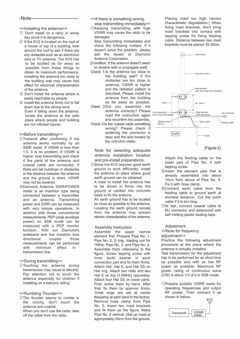
Placing mast too high causes characteristic degradation.) When fixing mast brackets, don't bring mast brackets into contact with tapping screw fro fixing feeding cable. Distance between two mast brackets must be placed 20-30cm.
④Attach the feeding cable on the lower part of Pipe No. 5 with tapping screw.⑤Insert the element pipe that is already assembled into about 10cm from above of Pipe No. 5. Fix it with hose clamp.⑥Connect earth cable from the feeding cable to ground earth at shortest distance. Cut the earth cable if it is too long. ⑦At last, connect coaxial cable to MJ connector and waterproof with self melting plastic sealing tape.
・Adjustment <<Note for frequency adjustment>>Practice the following adjustment procedure at the place where the antenna is actually installed.Test transmission for the adjustment has to be performed for as short time as possible and with as low RF power as possible. Maximum RF power rating of continuous wave (CW) is about 1/3 of it in SSB mode.
①Prepare suitable VSWR meter for operating frequencies and output RF power. Then connect it as shown in below.
↓
↓
↑
↑
3.5MHzNormal position
7MHzNormal position
②Adjustment procedure can be started from higher frequency (7MHz). Transmit at desired frequency and change the location and length of hat to have lowest VSWR at the frequency.
・ Resonant frequency variations by capacity hat location and hat element length combinations.Please refer to the following chart to find out changes in resonant frequency bandwidth by capacity hat location and hat element length combinations. By changing the hat location up and down, resonant frequency of the antenna changes within selected variable resonant frequency bandwidth.
Capacity hat location and the hat length combinations chart.
Combinations Frequency range Frequency3.5MHz
↓↓
↓↓↓
7MHz
↓↓↓
Hat 4pcs
Hat 2pcs + Hat S 2pcs(Standard)
Hat S 4pcs
Hat S 2pcs +
Hat SS 2pcs
Hat SS 4pcs
Hat SS 2pcs
Hat S 2pcsHat SS 4pcs(Standard)
Hat SS 2pcs
No Hat
3.450-3.515MHz
3.515-3.575MHz
3.595-3.665MHz
3.660-3.720MHz
3.725-3.770MHz
3.765-3.810MHz7.00-7.05MHz
7.05-7.10MHz
7.10-7.15MHz7.15-7.20MHz
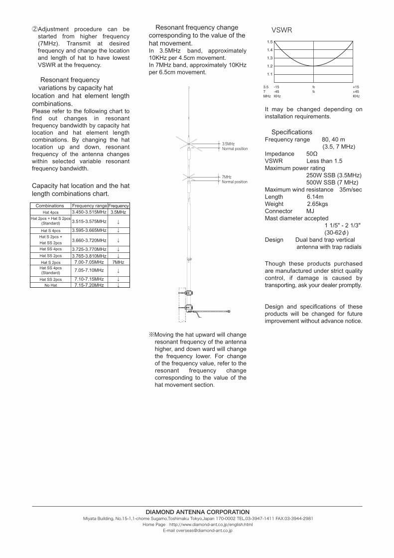
3.5 -15 f0 +157 -45 f0 +45MHz KHz KHz
1.5
1.4
1.3
1.2
1.1
・VSWR
It may be changed depending on installation requirements.
・SpecificationsFrequency range 80, 40 m (3.5, 7 MHz)Impedance 50ΩVSWR Less than 1.5Maximum power rating 250W SSB (3.5MHz) 500W SSB (7 MHz)Maximum wind resistance 35m/secLength 6.14m Weight 2.65kgsConnector MJMast diameter accepted 1 1/5" - 2 1/3" (30-62φ)Design Dual band trap vertical antenna with trap radials
Though these products purchased are manufactured under strict quality control, if damage is caused by transporting, ask your dealer promptly.
Design and specifications of these products will be changed for future improvement without advance notice.
・Resonant frequency change corresponding to the value of the hat movement.In 3.5MHz band, approximately 10KHz per 4.5cm movement.In 7MHz band, approximately 10KHz per 6.5cm movement.
※Moving the hat upward will change resonant frequency of the antenna higher, and down ward will change the frequency lower. For change of the frequency value, refer to the resonant frequency change corresponding to the value of the hat movement section.
DIAMOND ANTENNA CORPORATION Miyata Building, No.15-1,1-chome Sugamo,Toshimaku Tokyo,Japan 170-0002 TEL.03-3947-1411 FAX.03-3944-2981
Home Page http://www.diamond-ant.co.jp/english.htmlE-mail [email protected]