7Φ SERIES Metal Oxide Varistors (MOV) Data Sheet€¦ · · 2018-04-17Wide operating voltage (V...
12
7Φ SERIES Revision:13-Apr.-18 1 / 12 www.brightking.com Metal Oxide Varistors (MOV) Data Sheet Features ■ Wide operating voltage (V 1mA ) range from 18V to 820V ■ Fast responding to transient over-voltage ■ Large absorbing transient energy capability ■ Low clamping ratio and no follow-on current ■ Meets MSL level 1, per J-STD-020 ■ Operating Temperature:-40℃ ~ +85℃ ■ Storage Temperature:-40℃ ~ +125℃ ■ Safety certification: UL: E327997 CSA: 246579 VDE: 40027827 Applications ■ Transistor, diode, IC, thyristor or triac semiconductor protection ■ Surge protection in consumer electronics ■ Surge protection in industrial electronics ■ Surge protection in electronic home appliances, gas and petroleum appliances ■ Relay and electromagnetic valve surge absorption Part Number Code
-
Upload
nguyencong -
Category
Documents
-
view
222 -
download
2
Transcript of 7Φ SERIES Metal Oxide Varistors (MOV) Data Sheet€¦ · · 2018-04-17Wide operating voltage (V...
7Φ SERIES
Revision:13-Apr.-18 1 / 12 www.brightking.com
Metal Oxide Varistors (MOV) Data Sheet Features ■ Wide operating voltage (V1mA) range from 18V to 820V ■ Fast responding to transient over-voltage ■ Large absorbing transient energy capability ■ Low clamping ratio and no follow-on current ■ Meets MSL level 1, per J-STD-020 ■ Operating Temperature:-40℃ ~ +85℃ ■ Storage Temperature:-40℃ ~ +125℃ ■ Safety certification: UL: E327997 CSA: 246579 VDE: 40027827 Applications ■ Transistor, diode, IC, thyristor or triac semiconductor protection ■ Surge protection in consumer electronics ■ Surge protection in industrial electronics ■ Surge protection in electronic home appliances, gas and petroleum appliances ■ Relay and electromagnetic valve surge absorption Part Number Code
7Φ SERIES
Revision:13-Apr.-18 2 / 12 www.brightking.com
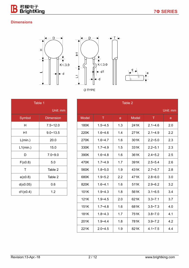
Dimensions
Table 1
Unit: mm
Table 2
Unit: mm
Symbol Dimension Model T e Model T e
H 7.5~12.0 180K 1.5~4.5 1.3 241K 2.1~4.6 2.0
H1 9.0~13.5 220K 1.6~4.6 1.4 271K 2.1~4.9 2.2
L(min.) 20.0 270K 1.6~4.7 1.6 301K 2.2~5.0 2.3
L1(min.) 15.0 330K 1.7~4.9 1.5 331K 2.2~5.1 2.3
D 7.0~9.0 390K 1.6~4.8 1.6 361K 2.4~5.2 2.5
F(±0.8) 5.0 470K 1.7~4.9 1.7 391K 2.5~5.4 2.6
T Table 2 560K 1.8~5.0 1.9 431K 2.7~5.7 2.8
e(±0.8) Table 2 680K 1.9~5.2 2.2 471K 2.8~6.0 3.0
d(±0.05) 0.6 820K 1.6~4.1 1.6 511K 2.9~6.2 3.2
d1(±0.4) 1.2 101K 1.9~4.3 1.8 561K 3.1~6.5 3.4
121K 1.9~4.5 2.0 621K 3.3~7.1 3.7
151K 1.7~4.8 1.6 681K 3.5~7.3 4.0
181K 1.8~4.3 1.7 751K 3.8~7.0 4.1
201K 1.9~4.4 1.8 781K 3.9~7.2 4.2
221K 2.0~4.5 1.9 821K 4.1~7.5 4.4
7Φ SERIES
Revision:13-Apr.-18 3 / 12 www.brightking.com
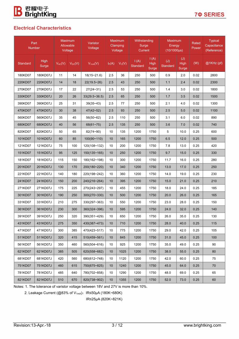
Electrical Characteristics
Part Number
Maximum Allowable Voltage
Varistor Voltage
Maximum Clamping Voltage
Withstanding Surge
Current
Maximum Energy
(10/1000μs)
RatedPower
Typical Capacitance(Reference)
Standard High
Surge VAC(V) VDC(V) V1mA(V) IP(A) VC(V)
I (A) Standard
I (A)High
Surge
(J) Standard
(J) High
Surge (W) @1KHz (pf)
180KD07 180KD07J 11 14 18(15~21.6) 2.5 36 250 500 0.9 2.0 0.02 2800
220KD07 220KD07J 14 18 22(19.5~26) 2.5 43 250 500 1.1 2.4 0.02 2300
270KD07 270KD07J 17 22 27(24~31) 2.5 53 250 500 1.4 3.0 0.02 1800
330KD07 330KD07J 20 26 33(29.5~36.5) 2.5 65 250 500 1.7 3.5 0.02 1500
390KD07 390KD07J 25 31 39(35~43) 2.5 77 250 500 2.1 4.0 0.02 1300
470KD07 470KD07J 30 38 47(42~52) 2.5 93 250 500 2.5 5.0 0.02 1100
560KD07 560KD07J 35 45 56(50~62) 2.5 110 250 500 3.1 6.0 0.02 890
680KD07 680KD07J 40 56 68(61~75) 2.5 135 250 500 3.6 7.0 0.02 740
820KD07 820KD07J 50 65 82(74~90) 10 135 1200 1750 5 10.0 0.25 600
101KD07 101KD07J 60 85 100(90~110) 10 165 1200 1750 6.5 12.0 0.25 500
121KD07 121KD07J 75 100 120(108~132) 10 200 1200 1750 7.8 13.0 0.25 420
151KD07 151KD07J 95 125 150(135~165) 10 250 1200 1750 9.7 15.0 0.25 330
181KD07 181KD07J 115 150 180(162~198) 10 300 1200 1750 11.7 16.0 0.25 280
201KD07 201KD07J 130 170 200(180~220) 10 340 1200 1750 13.0 17.0 0.25 250
221KD07 221KD07J 140 180 220(198~242) 10 360 1200 1750 14.0 19.0 0.25 230
241KD07 241KD07J 150 200 240(216~264) 10 395 1200 1750 15.0 21.0 0.25 210
271KD07 271KD07J 175 225 270(243~297) 10 455 1200 1750 18.0 24.0 0.25 185
301KD07 301KD07J 190 250 300(270~330) 10 500 1200 1750 20.0 26.0 0.25 165
331KD07 331KD07J 210 275 330(297~363) 10 550 1200 1750 23.0 28.0 0.25 150
361KD07 361KD07J 230 300 360(324~396) 10 595 1200 1750 24.0 32.0 0.25 140
391KD07 391KD07J 250 320 390(351~429) 10 650 1200 1750 26.0 35.0 0.25 130
431KD07 431KD07J 275 350 430(387~473) 10 710 1200 1750 28.0 40.0 0.25 115
471KD07 471KD07J 300 385 470(423~517) 10 775 1200 1750 29.0 42.0 0.25 105
511KD07 511KD07J 320 415 510(459~561) 10 845 1200 1750 31.0 45.0 0.25 100
561KD07 561KD07J 350 460 560(504~616) 10 925 1200 1750 35.0 49.0 0.25 90
621KD07 621KD07J 385 505 620(558~682) 10 1025 1200 1750 38.0 55.0 0.25 80
681KD07 681KD07J 420 560 680(612~748) 10 1120 1200 1750 42.0 60.0 0.25 75
751KD07 751KD07J 460 615 750(675~825) 10 1240 1200 1750 45.0 64.0 0.25 70
781KD07 781KD07J 485 640 780(702~858) 10 1290 1200 1750 48.0 69.0 0.25 65
821KD07 821KD07J 510 670 820(738~902) 10 1355 1200 1750 52.0 73.0 0.25 60
Notes: 1. The tolerance of varistor voltage between 18V and 27V is more than 10%.
2. Leakage Current (@83% of V1mA):IR≤50μA (180K~680K)
IR≤25μA (820K~821K)
7Φ SERIES
Revision:13-Apr.-18 4 / 12 www.brightking.com
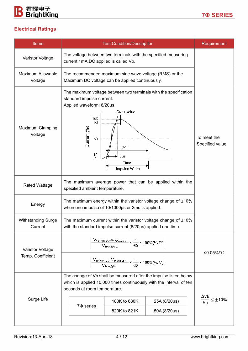
Electrical Ratings
Items Test Condition/Description Requirement
Varistor Voltage The voltage between two terminals with the specified measuring current 1mA.DC applied is called Vb.
To meet the Specified value
Maximum Allowable Voltage
The recommended maximum sine wave voltage (RMS) or the Maximum DC voltage can be applied continuously.
Maximum Clamping Voltage
The maximum voltage between two terminals with the specification standard impulse current. Applied waveform: 8/20μs
Rated Wattage The maximum average power that can be applied within the specified ambient temperature.
Energy The maximum energy within the varistor voltage change of ±10% when one impulse of 10/1000μs or 2ms is applied.
Withstanding Surge Current
The maximum current within the varistor voltage change of ±10% with the standard impulse current (8/20μs) applied one time.
Varistor Voltage Temp. Coefficient
≤0.05%/℃
Surge Life
The change of Vb shall be measured after the impulse listed below which is applied 10,000 times continuously with the interval of ten seconds at room temperature.
7Φ series 180K to 680K 25A (8/20μs)
820K to 821K 50A (8/20μs)
ΔVbVb 10%
7Φ SERIES
Revision:13-Apr.-18 5 / 12 www.brightking.com
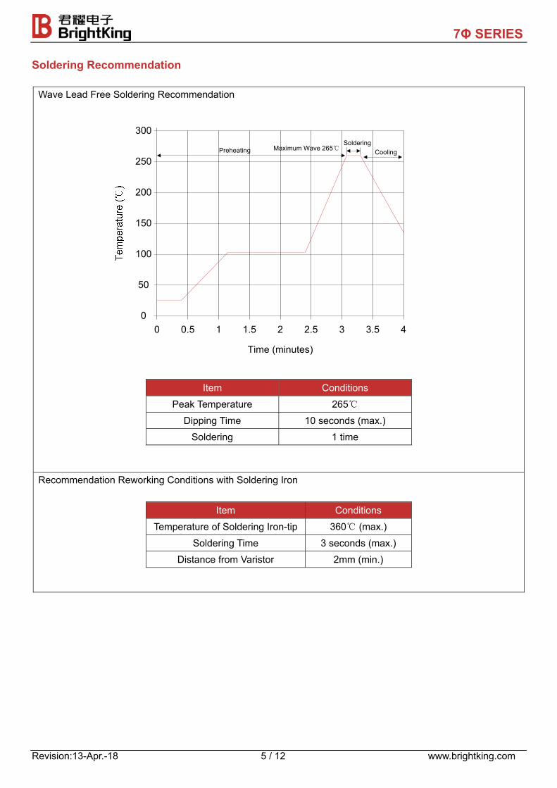
Soldering Recommendation
Wave Lead Free Soldering Recommendation
300
4
250
200
150
100
50
0
Time (minutes)
0 0.5 1 1.5 2 2.5 3 3.5
SolderingPreheating Maximum Wave 265℃ Cooling
Item Conditions
Peak Temperature 265℃
Dipping Time 10 seconds (max.) Soldering 1 time
Recommendation Reworking Conditions with Soldering Iron
Item Conditions
Temperature of Soldering Iron-tip 360℃ (max.)
Soldering Time 3 seconds (max.) Distance from Varistor 2mm (min.)
7Φ SERIES
Revision:13-Apr.-18 6 / 12 www.brightking.com
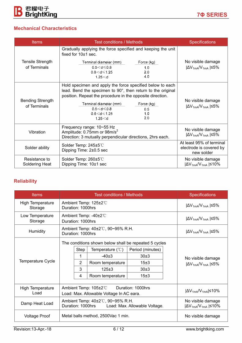
Mechanical Characteristics
Items Test conditions / Methods Specifications
Tensile Strength of Terminals
Gradually applying the force specified and keeping the unit fixed for 10±1 sec.
No visible damage |ΔV1mA/V1mA |≤5%
Bending Strength of Terminals
Hold specimen and apply the force specified below to each lead. Bend the specimen to 90°, then return to the original position. Repeat the procedure in the opposite direction.
No visible damage |ΔV1mA/V1mA |≤5%
Vibration Frequency range: 10~55 Hz Amplitude: 0.75mm or 98m/s2 Direction: 3 mutually perpendicular directions, 2hrs each.
No visible damage |ΔV1mA/V1mA |≤5%
Solder ability Solder Temp: 245±5℃ Dipping Time: 2±0.5 sec
At least 95% of terminal electrode is covered by
new solder Resistance to
Soldering Heat Solder Temp: 260±5℃ Dipping Time: 10±1 sec
No visible damage |ΔV1mA/V1mA |≤10%
Reliability
Items Test conditions / Methods Specifications
High Temperature Storage
Ambient Temp: 125±2℃ Duration: 1000hrs |ΔV1mA/V1mA |≤5%
Low Temperature Storage
Ambient Temp: -40±2℃ Duration: 1000hrs
|ΔV1mA/V1mA |≤5%
Humidity Ambient Temp: 40±2℃, 90~95% R.H. Duration: 1000hrs |ΔV1mA/V1mA |≤5%
Temperature Cycle
The conditions shown below shall be repeated 5 cycles
Step Temperature (℃) Period (minutes)1 -40±3 30±3 2 Room temperature 15±3 3 125±3 30±3 4 Room temperature 15±3
No visible damage |ΔV1mA/V1mA |≤5%
High Temperature Load
Ambient Temp: 105±2℃ Duration: 1000hrs Load: Max. Allowable Voltage In AC eara.
|ΔV1mA/V1mA|≤10%
Damp Heat Load Ambient Temp: 40±2℃, 90~95% R.H. Duration: 1000hrs Load: Max. Allowable Voltage.
No visible damage |ΔV1mA/V1mA |≤10%
Voltage Proof Metal balls method, 2500Vac 1 min. No visible damage
7Φ SERIES
Revision:13-Apr.-18 7 / 12 www.brightking.com
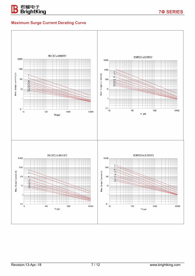
Maximum Surge Current Derating Curve
7Φ SERIES
Revision:13-Apr.-18 8 / 12 www.brightking.com
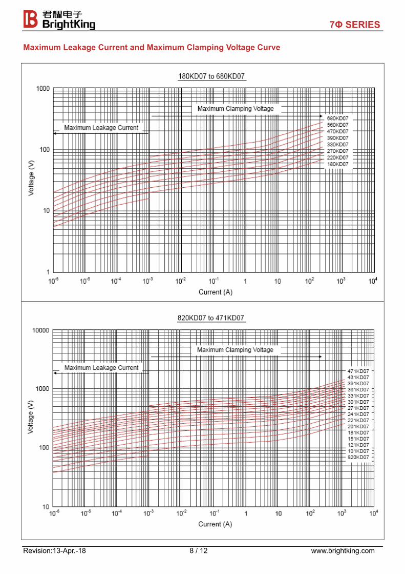
Maximum Leakage Current and Maximum Clamping Voltage Curve
7Φ SERIES
Revision:13-Apr.-18 9 / 12 www.brightking.com
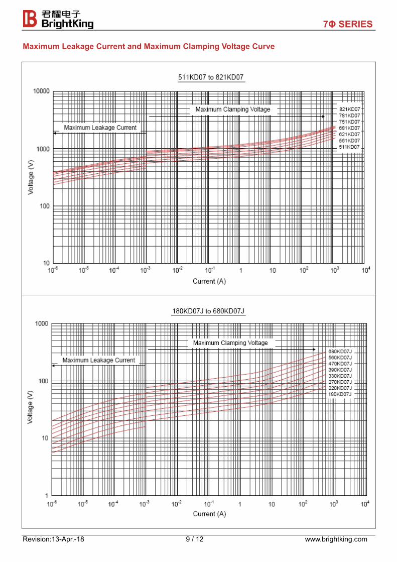
Maximum Leakage Current and Maximum Clamping Voltage Curve
7Φ SERIES
Revision:13-Apr.-18 10 / 12 www.brightking.com
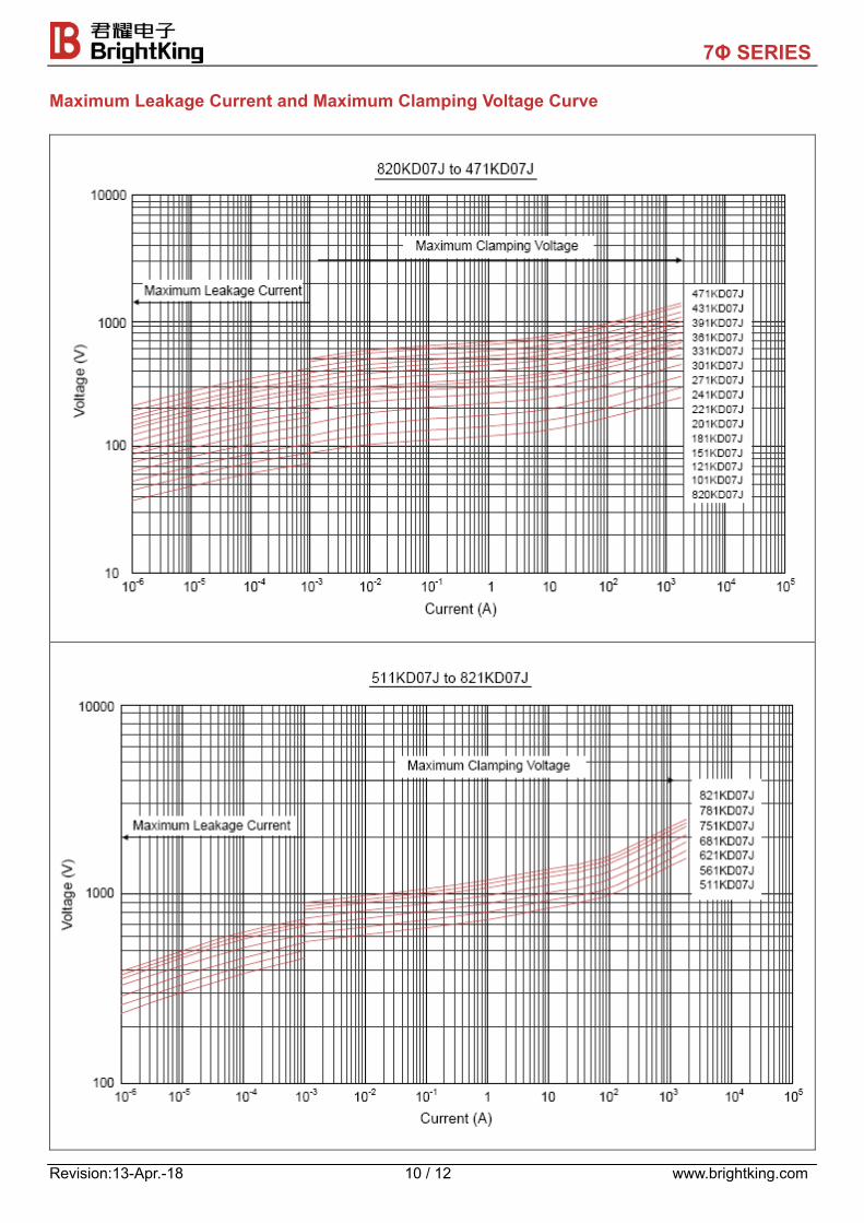
Maximum Leakage Current and Maximum Clamping Voltage Curve
7Φ SERIES
Revision:13-Apr.-18 11 / 12 www.brightking.com
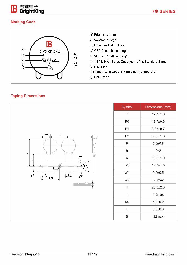
Marking Code
VDE
Taping Dimensions
Symbol Dimensions (mm)
P 12.7±1.0
P0 12.7±0.3
P1 3.85±0.7
P2 6.35±1.3
F 5.0±0.8
h 0±2
W 18.0±1.0
W0 12.0±1.0
W1 9.0±0.5
W2 3.0max
H 20.0±2.0
I 1.0max
D0 4.0±0.2
t 0.6±0.3
B 32max
7Φ SERIES
Revision:13-Apr.-18 12 / 12 www.brightking.com
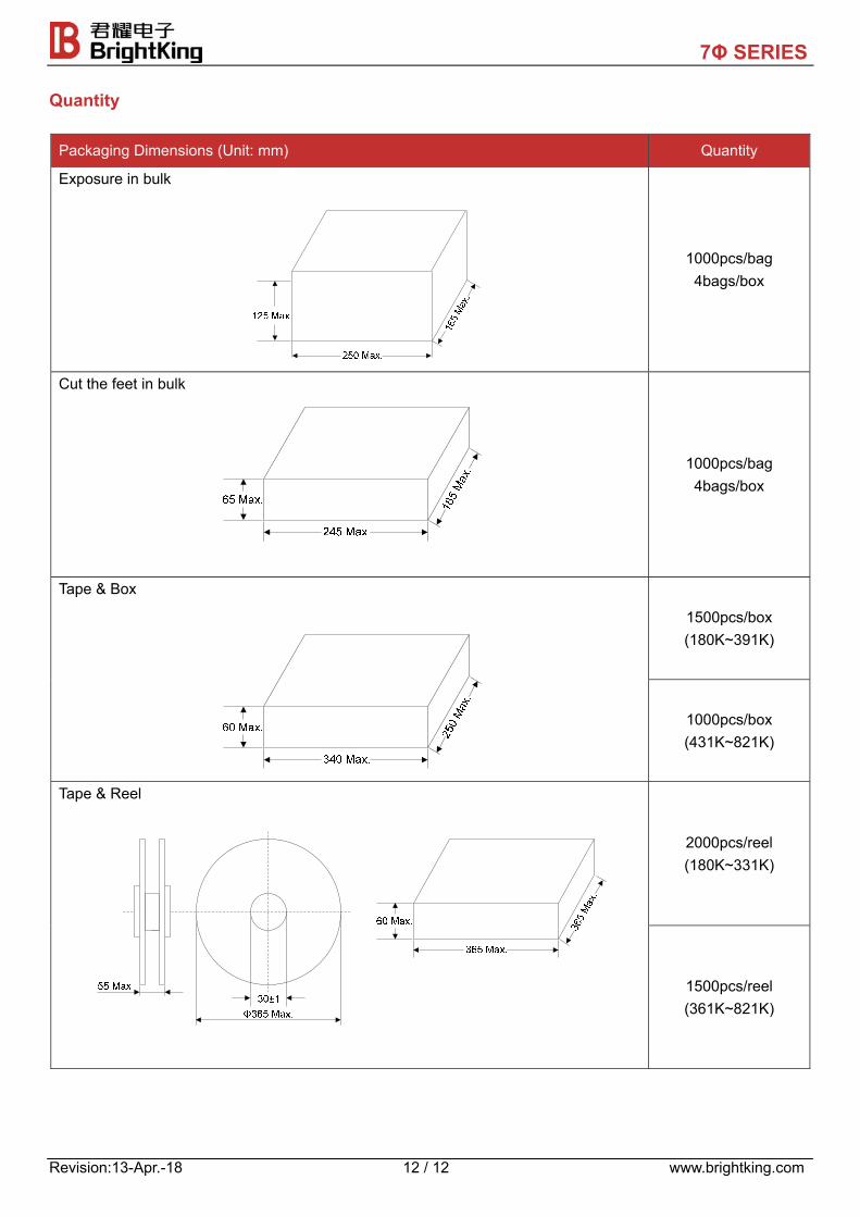
Quantity
Packaging Dimensions (Unit: mm) Quantity
Exposure in bulk
1000pcs/bag 4bags/box
Cut the feet in bulk
1000pcs/bag 4bags/box
Tape & Box
1500pcs/box (180K~391K)
1000pcs/box (431K~821K)
Tape & Reel
2000pcs/reel (180K~331K)
1500pcs/reel (361K~821K)