56157 24 ch24 p335-360
22
Wave Optics 339 PROBLEM SOLUTIONS 24.1 The location of the bright fringe of order m (measured from the position of the central maximum) is ( ) ( ) , , , y Ldmm m bright 2, = = ± ± λ 0 1 . . .. Thus, the spacing between successive bright fringes is Δy y y Ld m m m bright bright bright = ( ) − ( ) = ( ) + ( ) +1 1 λ − ( ) = λ λ Ldm Ld Thus, the wavelength of the laser light must be λ = ( ) = × ( ) × ( ) − − Δy d L bright cm m 1 58 10 0 200 10 2 3 . . 5 00 6 32 10 632 7 . . m m nm = × = − 24.2 (a) For a bright fringe of order m, the path difference is δ λ = m , where m = 012 , , , K . At the location of the third order bright fringe, m = 3 and δ λ μ = = ( ) = × = 3 3 589 1 77 10 1 77 3 nm nm m . . (b) For a dark fringe, the path difference is δ λ = + ⎛ ⎝ ⎜ ⎞ ⎠ ⎟ m 1 2 , where m = 012 , , , K . At the third dark fringe, m = 2 and δ λ μ = + ⎛ ⎝ ⎜ ⎞ ⎠ ⎟ = ( ) = × = 2 1 2 5 2 589 1 47 10 1 47 3 nm nm . . m 24.3 (a) The distance between the central maximum and the first order bright fringe is Δy y y L d m m = − = = = bright bright 1 0 λ , or Δy L d = = × ( ) ( ) × = − − λ 546 1 10 1 20 0 250 10 2 9 3 . . . m m m . . 62 10 2 62 3 × = − m mm (b) The distance between the first and second dark bands is Δy y y L d m m = − = = = = dark dark mm 1 0 2 62 λ . as in (a) above. 24.4 The location of the dark fringe of order m (measured from the position of the central maximum) is given by ( ) ( )( ) y Ld m m dark = + λ 1 2 , where m = ± ± 0, 1, 2, . . . . Thus, the spacing between the first and second dark fringes will be Δy y y Ld Ld m m = ( ) − ( ) = ( ) + ( ) − ( ) = = dark dark 1 0 1 2 1 0 λ λ + ( ) = 1 2 λ Ld or Δy = × ( ) ( ) × = × − − 5 30 10 2 00 0 300 10 3 53 1 7 3 . . . . m m m 0 3 53 3 − = m mm . 24.5 (a) From d m sin θ λ = , the angle for the m = 1 maximum for the sound waves is θ λ = ⎛ ⎝ ⎞ ⎠ = ⎛ ⎝ ⎜ ⎞ ⎠ ⎟ ⎡ ⎣ ⎢ ⎤ ⎦ ⎥ = − − sin sin s 1 1 m d m d f v sound in . . − ⎛ ⎝ ⎜ ⎞ ⎠ ⎟ ⎡ ⎣ ⎢ ⎤ ⎦ ⎥ = 1 1 0 300 354 2 000 36 2 m ms Hz ° continued on next page
Transcript of 56157 24 ch24 p335-360
Wave Optics 339
PROBLEM SOLUTIONS
24.1 The location of the bright fringe of order m (measured from the position of the central maximum) is ( ) ( ) , , ,y L d m mmbright 2, = = ± ±λ 0 1 . . .. Thus, the spacing between successive bright fringes is
Δy y y L d m
m mbright bright bright= ( ) − ( ) = ( ) +( )+1
1λ −− ( ) =λ λL d m L d
Thus, the wavelength of the laser light must be
λ =
( )=
×( ) ×( )− −Δy d
Lbright cm m1 58 10 0 200 102 3. .
55 006 32 10 6327
..
m m nm= × =−
24.2 (a) For a bright fringe of order m, the path difference is δ λ= m , where m = 0 1 2, , ,K. At the location of the third order bright fringe, m = 3 and
δ λ μ= = ( ) = × =3 3 589 1 77 10 1 773 nm nm m. .
(b) For a dark fringe, the path difference is δ λ= +⎛⎝⎜
⎞⎠⎟m
1
2, where m = 0 1 2, , ,K.
At the third dark fringe, m = 2 and
δ λ μ= +⎛
⎝⎜⎞⎠⎟ = ( ) = × =2
1
2
5
2589 1 47 10 1 473 nm nm . . mm
24.3 (a) The distance between the central maximum and the fi rst order bright fringe is
Δy y yL
dm m= − =
= =bright bright1 0
λ, or
ΔyL
d= =
×( )( )×
=−
−
λ 546 1 10 1 20
0 250 102
9
3
. .
.
m m
m.. .62 10 2 623× =− m mm
(b) The distance between the fi rst and second dark bands is
Δy y yL
dm m= − = =
= =dark dark mm1 0
2 62λ
. as in (a) above.
24.4 The location of the dark fringe of order m (measured from the position of the central maximum) is given by ( ) ( )( )y L d mmdark = +λ 1
2 , where m = ± ±0, 1, 2, . . . . Thus, the spacing between the fi rst and second dark fringes will be
Δy y y L d L dm m
= ( ) − ( ) = ( ) +( ) − ( )= =dark dark1 0121 0λ λ ++( ) =1
2 λL d
or Δy =×( )( )
×= ×
−
−
5 30 10 2 00
0 300 103 53 1
7
3
. .
..
m m
m00 3 533− = m mm.
24.5 (a) From d msinθ λ= , the angle for the m = 1 maximum for the sound waves is
θ λ= ⎛⎝
⎞⎠ =
⎛⎝⎜
⎞⎠⎟
⎡
⎣⎢
⎤
⎦⎥ =− −sin sin s1 1m
d
m
d f
vsound iin.
.− ⎛⎝⎜
⎞⎠⎟
⎡
⎣⎢
⎤
⎦⎥ =1 1
0 300
354
2 00036 2
m
m s
Hz°°
continued on next page
56157_24_ch24_p335-360.indd 33956157_24_ch24_p335-360.indd 339 3/20/08 4:55:44 AM3/20/08 4:55:44 AM
340 Chapter 24
(b) For 3.00-cm microwaves, the required slit spacing is
d
m= =( )( )
( ) =λθsin
.
sin ..
1 3 00
36 25 08
m cm
°
(c) The wavelength is λ θ= d msin ; and if this is light, the frequency is
fc m c
d= = =
( ) ×( )×( )−λ θsin
.
s
1 3 00 108 m s
1.00 10 m6 iin ..
36 25 08 1014
°= × Hz
24.6 (a) The location of the bright fringe of order m (measured from the position of the central maximum) is ( ) ( ) , , ,y m mmbright 2,= = ± ±λL d 0 1 K.
If ( ) ( ) .y ym mbright bright cm= =− =3 0 5 30 , then 3 0 5 30( ) .λL d − = cm , and
λ =
( ) =×( ) ×( )− −
5 30
3
5 30 10 0 050 0 102 3. . . cm m md
L 33 1 505 89 10 5897
..
m m nm( ) = × =−
(b) The separation between adjacent bright fringes is Δy L dbright = λ , or
Δybright
m m
m=
×( )( )×
=−
−
589 10 1 50
0 050 0 10
9
3
.
.11 77 10 1 772. .× =− m cm
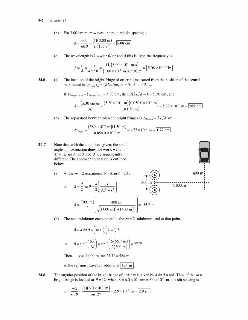
24.7 Note that, with the conditions given, the small angle approximation does not work well. That is, sin , tan , and θ θ θ are signifi cantly different. The approach to be used is outlined below.
(a) At the m = 2 maximum, δ θ λ= =d sin 2 ,
or λ θ= =+
⎛
⎝⎜
⎞
⎠⎟
d d y
L y2 2 2 2sin
λ =( )
( ) + ( )
⎡
⎣
⎢⎢
⎤
⎦
⎥⎥
=300
2
400
4005
2 2
m m
1 000 m m55 7. m
(b) The next minimum encountered is the m = 2 minimum; and at that point,
δ θ λ λ= = +⎛
⎝⎜⎞⎠⎟ =d msin
1
2
5
2
or θ λ= ⎛⎝⎜
⎞⎠⎟ =
( )( )
⎛⎝⎜
− −sin sin.1 15
2
5 55 7
2 300d
m
m
⎞⎞⎠⎟
= °27 7.
Then, y = ( ) =1 000 27 7 524 m mtan . °
so the car must travel an additional 124 m .
24.8 The angular position of the bright fringe of order m is given by d msinθ λ= . Thus, if the m = 1 bright fringe is located at θ = 12° when λ = × = × −6 0 10 6 0 102 7. . nm m, the slit spacing is
d
m= =( ) ×( )
°= × =
−−λ
θsin
.
sin.
1 6 0 10
122 9 10 2
76
m m ..9 mμ
56157_24_ch24_p335-360.indd 34056157_24_ch24_p335-360.indd 340 3/20/08 1:38:18 AM3/20/08 1:38:18 AM
Wave Optics 341
24.9 The location of the bright fringe of order m (measured from the position of the central maximum) is ( ) ( ) , , ,y m mmbright 2,= = ± ±λL d 0 1 K. If the m = 1 bright fringe is located at y = 3 40. mm when d L= =0 500 3 30. . mm and m, the wavelength of the light is
λ = =
×( ) ×( )− −( ) . .y d
mLmbright m m3 40 10 0 500 103 3
11 3 305 15 10 5157
( )( ) = × =−
..
m m nm
24.10 The angular deviation from the line of the central maximum is given by
θ = ⎛
⎝⎜⎞⎠⎟ = ⎛
⎝⎜⎞⎠⎟ =− −tan tan
..1 1 1 80
0y
L
cm
140 cm7737°
(a) The path difference is then
δ θ= = ( ) ( ) = × =−d sin . sin . .0 150 0 737 1 93 10 3 mm mm° 11.93 mμ
(b) δ λ λ= ×( ) ×⎛⎝⎜
⎞⎠⎟ =−
−1 93 10643 10
3 0069. . m m
(c) Since the path difference for this position is a whole number of wavelengths, the waves
interfere constructively and produce a maximum at this spot.
24.11 The distance between the central maximum (position of A) and the fi rst minimum is
yL
dm
L
dm
= +⎛⎝⎜
⎞⎠⎟ =
=
λ λ1
2 20
Thus, dL
y= =
( )( )( ) =λ
2
3 00 150
2 20 011 3
.
..
m m
m m
24.12 (a) The angular position of the bright fringe of order m is given by d msinθ λ= , or θ λm m d= −sin ( )1 . If d = 25λ , the fi rst three bright fringes are found at
θ11 1
252 3= ⎛
⎝⎜⎞⎠⎟ =−sin . ° , θ2
1 2
254 6= ⎛
⎝⎜⎞⎠⎟ =−sin . ° , and θ3
1 3
256 9= ⎛
⎝⎜⎞⎠⎟ =−sin . °
(b) The angular position of the dark fringe of order m is given by d msin ( )θ λ= + 12 , or
θ λm m d m= +[ ] = ± ±−sin ( ) , , ,1 12 0 1 2,K. If d = 25λ, the fi rst three dark fringes are
found at
θ01
12
251 1= ⎛
⎝⎜⎞⎠⎟ =−sin . ° , θ1
13
2
253 4= ⎛
⎝⎜⎞⎠⎟ =−sin . ° , and θ2
15
2
255 7= ⎛
⎝⎜⎞⎠⎟ =−sin . °
(c) The answers are evenly spaced because the angles are small and θ θ≈ sin . At larger
angles, the approximation breaks down and the spacing isn’t so regular.
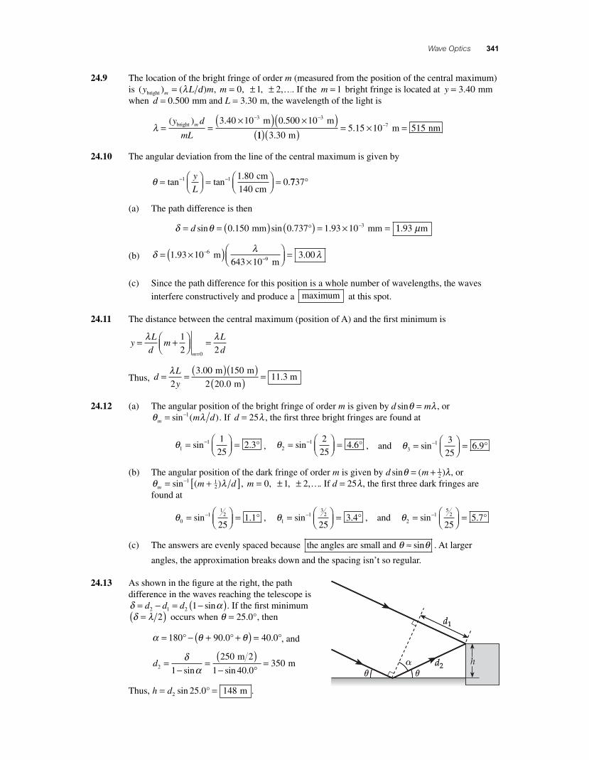
24.13 As shown in the fi gure at the right, the path difference in the waves reaching the telescope is δ α= − = −( )d d d2 1 2 1 sin . If the fi rst minimum δ λ=( )2 occurs when θ = 25 0. °, then
α θ θ= − + +( ) =180 90 0 40 0° ° °. . , and
d2 1
250
1 40 0350=
−=
( )− °
=δαsin sin .
m 2 m
Thus, h d= =2 25 0 148sin . ° m .
56157_24_ch24_p335-360.indd 34156157_24_ch24_p335-360.indd 341 3/20/08 4:44:43 AM3/20/08 4:44:43 AM
342 Chapter 24
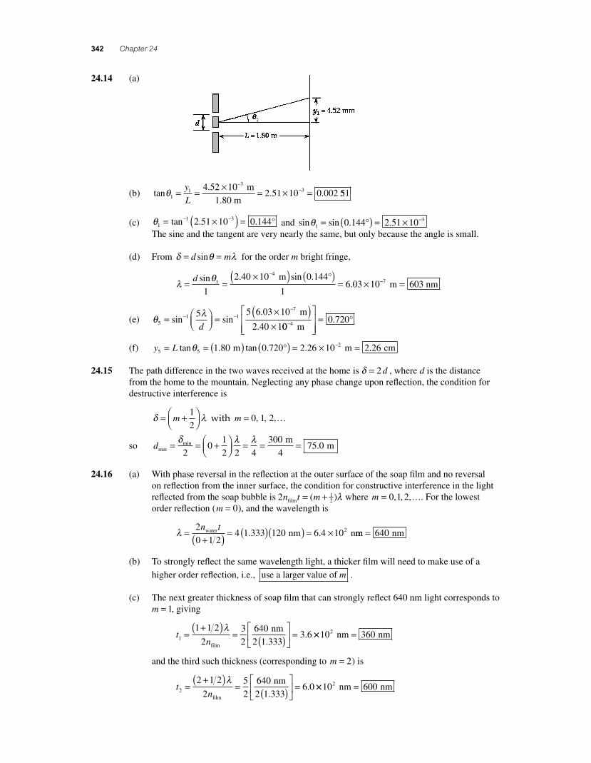
24.14 (a)
(b) tan.
. .θ1
334 52 10
2 51 10 0 002= = × = × =−
−y
L1 m
1.80 m551
(c) θ11 32 51 10 0 144= ×( ) =− −tan . . ° and sin sin . .θ1
30 144 2 51 10= ( ) = × −°The sine and the tangent are very nearly the same, but only because the angle is small.
(d) From δ θ λ= =d msin for the order m bright fringe,
λ θ= =
×( ) ( )= ×
−d sin . sin .
.1
4
1
2 40 10 0 144
16 03 10
m ° −− =7 603 m nm
(e) θ λ5
1 17
5 5 6 03 10
2 40 1= ⎛
⎝⎜⎞⎠⎟ =
×( )×
− −−
sin sin.
.d
m
000 7204−
⎡
⎣⎢⎢
⎤
⎦⎥⎥
= m
. °
(f) y L5 521 80 0 720 2 26 10 2= = ( ) ( ) = × =−tan . tan . .θ m m° ..26 cm
24.15 The path difference in the two waves received at the home is δ = 2 d , where d is the distance from the home to the mountain. Neglecting any phase change upon refl ection, the condition for destructive interference is
δ λ= +⎛⎝⎜
⎞⎠⎟m
1
2 with m = …0 1 2, , ,
so dmin
m
4 m= = +⎛
⎝⎜⎞⎠⎟ = = =δ λ λmin .
20
1
2 2 4
30075 0
24.16 (a) With phase reversal in the refl ection at the outer surface of the soap fi lm and no reversal on refl ection from the inner surface, the condition for constructive interference in the light refl ected from the soap bubble is 2 1
2n mfilmt = +( )λ where m = 0 1 2, , ,K. For the lowest order refl ection (m = 0), and the wavelength is
λ =
+( ) = ( )( ) = ×2
0 1 24 1 333 120 6 4 102n twater nm n. . mm nm= 640
(b) To strongly refl ect the same wavelength light, a thicker fi lm will need to make use of a
higher order refl ection, i.e., use a larger value of m .
(c) The next greater thickness of soap fi lm that can strongly refl ect 640 nm light corresponds to m = 1, giving
tn1
1 1 2
2
3
2
6403 6=
+( )= ( )
⎡
⎣⎢
⎤
⎦⎥ =
λ
film
nm
2 1.333. ×× =10 3602 nm nm
and the third such thickness (corresponding to m = 2) is
tn2
2 1 2
2
5
2
6406 0=
+( )= ( )
⎡
⎣⎢
⎤
⎦⎥ =
λ
film
nm
2 1.333. ×× =10 6002 nm nm
56157_24_ch24_p335-360.indd 34256157_24_ch24_p335-360.indd 342 3/20/08 1:38:20 AM3/20/08 1:38:20 AM
Wave Optics 343
24.17 Light refl ecting from the fi rst (glass-iodine) interface suffers a phase reversal, but light refl ecting at the second (iodine-glass) interface does not have a phase reversal. Thus, the condition for con-structive interference in the refl ected light is 2 1
2n t mfilm = +( )λ with m = 0 1 2, , , K. The smallest fi lm thickness capable of strongly refl ecting the incident light is
t
nmin
..=
+( )= ×
( ) =0 1 2
2
6 00 1085 4
2λ
film
nm
4 1.756 nm
24.18 (a) With nair
< noil
< nwater
, phase reversals are experienced by light refl ecting at both surfaces of the oil fi lm, an upper air-oil interface and a lower oil-water interface. Under these condi-tions, the requirement for constructive interference is 2 1n t mfilm = λ with m1 0 1 2= , , ,K, and the requirement for destructive interference is 2 2
12n t mfilm = +( )λ with m2 0 1 2= , , ,K.
To have the thinnest fi lm that produces simultaneous constructive interference of λ1 640= nm and destructive interference of λ2 512= nm, it is necessary that
2 640
1
25121 2n t m mfilm nm nm= ( ) = +⎛
⎝⎜⎞⎠⎟ ( )
where both m m1 2 and are the smallest integers for which this is true. It is found that m m1 2 2= = are the smallest integer values that will satisfy this condition, giving the minimum acceptable fi lm thickness as
tm
n
m
nmin = =+( )
=( )1 1 2
12 2
2 2
2 640
2 1
λ λ
film film
nm
..
.
.25
2 5 512
2 1 25512( ) =
( )( )( ) =
nm nm
(b) From the discussion above, it is seen that in order to have a fi lm thickness that produces simultaneous constructive interference of 640-nm light and destructive interference of 512-nm light, it is necessary that
m m m1 2640
1
2512 nm nm or ( ) = +⎛
⎝⎜⎞⎠⎟ ( ) 11 2
640
512
1
2
nm
nm⎛⎝⎜
⎞⎠⎟ = +m
This gives 1 251
22 11 2 1 2.( ) = + = +m m m m or 2.5 .
24.19 With n n n ncoating air coating lens and > > , light refl ecting at the air-coating boundary experiences a phase reversal, but light refl ecting from the coating-lens boundary does not. Therefore, the condition for destructive interference in the two refl ected waves is
2n t mcoating = λ where m = …0 1 2, , ,
For fi nite wavelengths, the lowest allowed value of m is m = 1 . Then, if t n= =177 4 1 55. . nm and coating , the wavelength associated with this lowest order destructive interference is
λ1
2
12 1 55 177 4 550= = ( )( ) =
n tcoating nm nm. .
56157_24_ch24_p335-360.indd 34356157_24_ch24_p335-360.indd 343 3/20/08 4:50:57 AM3/20/08 4:50:57 AM
344 Chapter 24
24.20 Since n n nair oil water< < , light refl ected from both top and bottom surfaces of the oil fi lm experi-ences phase reversal, resulting in zero net phase difference due to refl ections. Therefore, the condition for constructive interference in refl ected light is
2 t m mnn= =λ λ
film
, or t mn
=⎛⎝⎜
⎞⎠⎟
λ2 film
where m = …0 1 2, , ,
Assuming that m = 1, the thickness of the oil slick is
tn
= = ( ) =( )12
60033
λfilm
nm
2 1.292 nm
24.21 There will be a phase reversal of the radar waves refl ecting from both surfaces of the polymer, giving zero net phase change due to refl ections. The requirement for destructive interference in the refl ected waves is then
21
2t m n= +⎛
⎝⎜⎞⎠⎟ λ , or t m
n= +( )2 1
4
λfilm
where m = …0 1 2, , ,
If the fi lm is as thin as possible, then m = 0 and the needed thickness is
tn
= = ( ) =λ4
3 000 500
film
cm
4 1.50 cm
..
This anti-refl ectance coating could be easily countered by changing the wavelength of the radar — to 1.50 cm — now creating maximum refl ection!
24.22 (a) With n n nair water oil< < , refl ections at the air-oil interface experience a phase reversal, while refl ections at the oil-water interface experience no phase reversal. Thus, with one phase reversal at the surfaces, the condition for constructive interference in the light refl ected by the fi lm is 2 1
2n t mfilm = +( )λ , where m is any positive integer. Thus,
λm
t
m m m=
+= ( )( )
+=
+2 2 1 45 280 812
12
12
nfilm nm nm.112
0, 1, 2, 3,m = K
The possible wavelengths are: λ λ λ03
1 21 62 10 541 325= × = =. nm, nm, nm,K
Of these, only λ1 541= nm (green) is in the visible portion of the spectrum.
(b) The wavelengths that will be most strongly transmitted are those that suffer destructive interference in the refl ected light. With one phase reversal at the surfaces, the condition for destructive interference in the light refl ected by the fi lm is 2n t mfilm = λ , where m is any positive, nonzero, integer. The possible wavelengths are
λm
n t
m m mm= = ( )( )
= =2 2 1 45 280 812film nm nm.11, 2, 3,K
or λ λ λ1 2 3812 406 271= = =nm, nm, nm,K
of which only λ2 406= nm (violet) is in the visible spectrum.
56157_24_ch24_p335-360.indd 34456157_24_ch24_p335-360.indd 344 3/20/08 1:38:22 AM3/20/08 1:38:22 AM
Wave Optics 345
24.23 (a) For maximum transmission, we want destructive interference in the light refl ected from the front and back surfaces of the fi lm.
If the surrounding glass has refractive index greater than 1.378, light refl ected from the front surface suffers no phase reversal, and light refl ected from the back does undergo phase reversal. This effect by itself would produce destructive interference, so we want the distance down and back to be one whole wavelength in the fi lm. Thus, we require that
2t nn= =λ λ film or tn
= = ( ) =λ2
656 3238
film
nm
2 1.378 nm
.
(b) The fi lter will expand. As t increases in 2n tfilm = λ, so does λ increase .
(c) Destructive interference for refl ected light happens also for λ in 2 2t n= λ film , or
λ = = ( )( ) =n tfilm nm nm1 378 238 328. (near ultraviolet)
24.24 Light refl ecting from the lower surface of the air layer experiences phase reversal, but light refl ecting from the upper surface of the layer does not. The requirement for a dark fringe (destruc-tive interference) is then
2 t m mn
mn= =⎛⎝⎜
⎞⎠⎟
=λ λ λair
, where m = …0 1 2, , ,
At the thickest part of the fi lm t =( )2 00. mμ , the order number is
mt= =
×( )×
=−
−
2 2 2 00 10
546 1 107 32
6
9λ.
..
m
m
Since m must be an integer, m = 7 is the order of the last dark fringe seen. Counting the m = 0
order along the edge of contact, a total of 8 dark fringes will be seen.
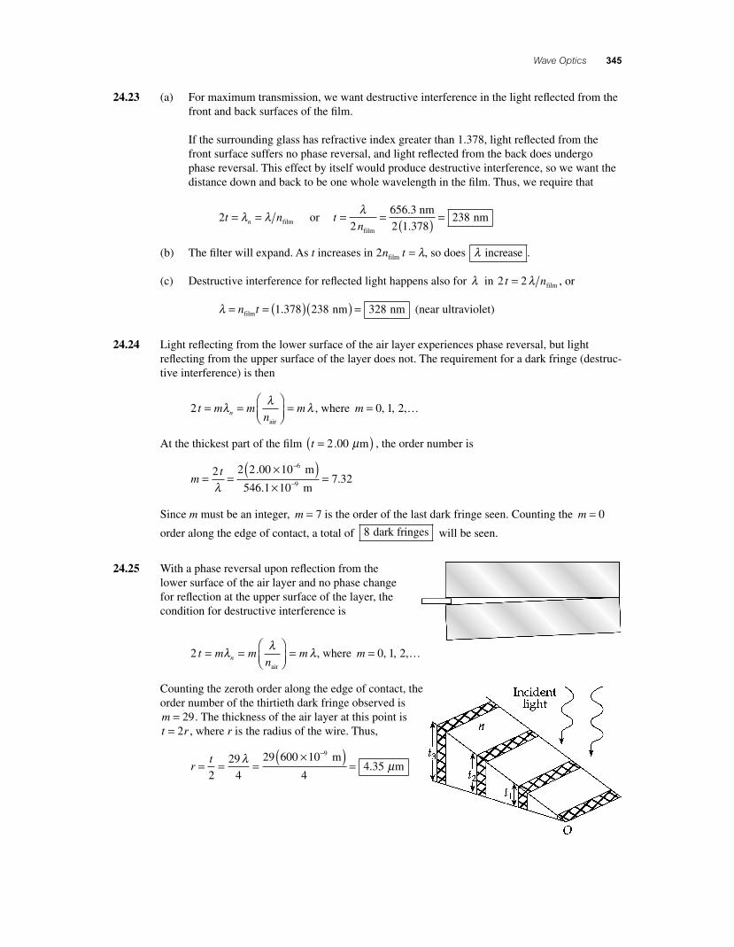
24.25 With a phase reversal upon refl ection from the lower surface of the air layer and no phase change for refl ection at the upper surface of the layer, the condition for destructive interference is
2 t m mn
mn= =⎛⎝⎜
⎞⎠⎟
=λ λ λair
, where m = …0 1 2, , ,
Counting the zeroth order along the edge of contact, the order number of the thirtieth dark fringe observed is m = 29. The thickness of the air layer at this point is t r= 2 , where r is the radius of the wire. Thus,
rt= = =
×( )=
−
2
29
4
29 600 10
44 35
9λ μ m
m.
56157_24_ch24_p335-360.indd 34556157_24_ch24_p335-360.indd 345 3/20/08 1:38:22 AM3/20/08 1:38:22 AM
346 Chapter 24
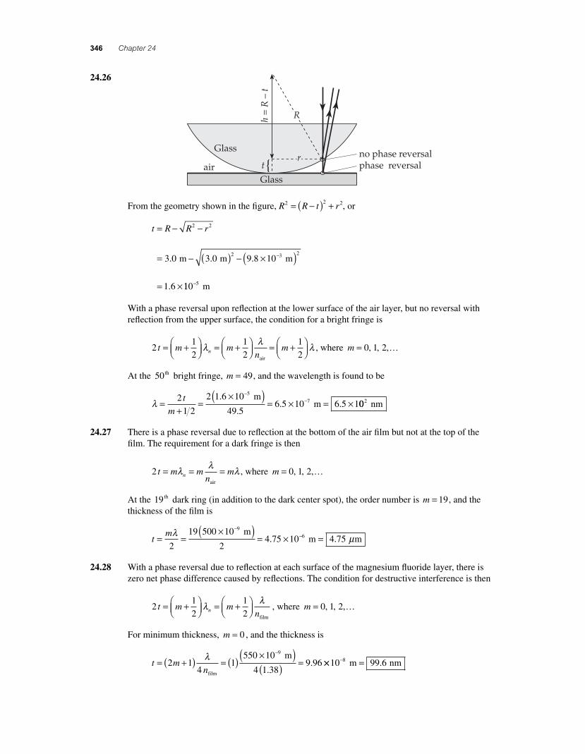
24.26
From the geometry shown in the fi gure, R R t r2 2 2= −( ) + , or
t R R r= − −
= − ( ) − ×( )
= ×
−
2 2
2 3 23 0 3 0 9 8 10
1 6
. . .
.
m m m
110 5− m
With a phase reversal upon refl ection at the lower surface of the air layer, but no reversal with refl ection from the upper surface, the condition for a bright fringe is
21
2
1
2
1
2t m m
nmn= +⎛
⎝⎜⎞⎠⎟ = +⎛
⎝⎜⎞⎠⎟ = +⎛
⎝⎜⎞⎠⎟λ λ λ
air
, where m = …0 1 2, , ,
At the 50th bright fringe, m = 49, and the wavelength is found to be
λ =+
=×( )
= × = ×−
−2
1 2
2 1 6 10
49 56 5 10 6 5 1
57t
m
.
.. .
m m 002 nm
24.27 There is a phase reversal due to refl ection at the bottom of the air fi lm but not at the top of the fi lm. The requirement for a dark fringe is then
2 t m mn
mn= = =λ λ λair
, where m = …0 1 2, , ,
At the 19th dark ring (in addition to the dark center spot), the order number is m = 19, and the thickness of the fi lm is
tm= =
×( )= × =
−−λ μ
2
19 500 10
24 75 10 4 75
96
m m m. .
24.28 With a phase reversal due to refl ection at each surface of the magnesium fl uoride layer, there is zero net phase difference caused by refl ections. The condition for destructive interference is then
21
2
1
2t m m
nn= +⎛⎝⎜
⎞⎠⎟ = +⎛
⎝⎜⎞⎠⎟λ λ
film
, where m = …0 1 2, , ,
For minimum thickness, m = 0 , and the thickness is
t mn
= +( ) = ( ) ×( )( ) =
−
2 14
1550 10
4 1 389 96
9λfilm
m
.. ×× =−10 99 68 m nm.
56157_24_ch24_p335-360.indd 34656157_24_ch24_p335-360.indd 346 3/20/08 1:38:23 AM3/20/08 1:38:23 AM
Wave Optics 347
24.29 There is a phase reversal upon refl ection at each surface of the fi lm and hence zero net phase difference due to refl ections. The requirement for constructive interference in the refl ected light is then
2 t m mnn= =λ λ
film
, where m = …1 2 3, , ,
With t = × =−1 00 10 1005. cm nm, and nfilm = 1 38. , the wavelengths intensifi ed in the refl ected light are
λ = =( )( )2 2 1 38 100n t
m mfilm nm.
, with m = …1 2 3, , ,
Thus, λ = …276 1 9 nm, 38 nm, 2.0 nm
and none of these wavelengths are in the visiblee spectrum .
24.30 The transmitted light is brightest when the refl ected light is a minimum (that is, the same condi-tions that produce destructive interference in the refl ected light will produce constructive interfer-ence in the transmitted light). As light enters the air layer from glass, any light refl ected at this surface has zero phase change. Light refl ected from the other surface of the air layer (where light is going from air into glass) does have a phase reversal. Thus, the condition for destructive inter-ference in the light refl ected from the air fi lm is 2 t m n= λ , m = …0 1 2, , , .
Since λ λ λ λn n= = =
film 1 00., the minimum nonzero plate separation satisfying this condition is
d t= = ( ) = =12
580290
λ nm
2 nm
24.31 In a single slit diffraction pattern, with the slit having width a, the dark fringe of order m occurs at angle θm , where sin ( )θ λm m a= and m = ± ± ±1, 2, 3,K. The location, on a screen located distance L from the slit, of the dark fringe of order m (measured from y = 0 at the center of the central maximum) is ( ) tan siny L L m L am m mdark = ≈ = ( )θ θ λ .
(a) The central maximum extends from the m = −1 dark fringe to the m = +1 dark fringe, so the width of this central maximum is
Central max. width dark dark= − = ⎛−( ) ( )y y
L
a1 1 1λ
⎝⎝⎜⎞⎠⎟ − −( )⎛
⎝⎜⎞⎠⎟ =
=×( )−
12
2 5 40 10 1 57
λ λL
a
L
a
. . m 00
0 200 108 10 10 8 103
3 m
m m mm
( )×
= × =−−
.. .
(b) The fi rst order bright fringe extends from the m = 1 dark fringe to the m = 2 dark fringe, or
Δy y yL
abright dark 2 dark 1( ) = ( ) − ( ) = ⎛⎝⎜
⎞⎠⎟ −
12 1
λ λLL
a
L
a⎛⎝⎜
⎞⎠⎟ =
=×( )( )
×
−
λ
5 40 10 1 50
0 200 10
7. .
.
m m−−
−= × =334 05 10 4 05
m m mm. .
Note that the width of the fi rst order bright fringe is exactly one-half the width of the central maximum.
56157_24_ch24_p335-360.indd 34756157_24_ch24_p335-360.indd 347 3/20/08 5:03:10 AM3/20/08 5:03:10 AM
348 Chapter 24
24.32 (a) Dark bands occur where sinθ λ= ( )m a . At the fi rst dark band, m = 1, and the distance from the center of the central maximum is
y L L La1
9
1 5600 10
0
= ≈ = ⎛⎝⎜
⎞⎠⎟
= ( ) × −
tan sin
.
θ θ λ
m m
... .
40 102 25 10 2 33
3
×⎛⎝⎜
⎞⎠⎟
= × =−−
m m mm
(b) The width of the central maximum is 2 2 2 25 4 51y = ( ) =. . mm mm
24.33 (a) Dark bands (minima) occur where sin ( )θ λ= m a . For the fi rst minimum, m = 1 and the distance from the center of the central maximum is y L L L a1 = ≈ = ( )tan sinθ θ λ . Thus, the needed distance to the screen is
L y
a= ⎛⎝⎜
⎞⎠⎟ = ×( ) ×
×−
−
13
3
0 85 100 75 10
λ.
. m
m
587.5 110 m m9−
⎛⎝⎜
⎞⎠⎟
= 1 1.
(b) The width of the central maximum is 2 2 0 1 71y = ( ) =.85 mm mm. .
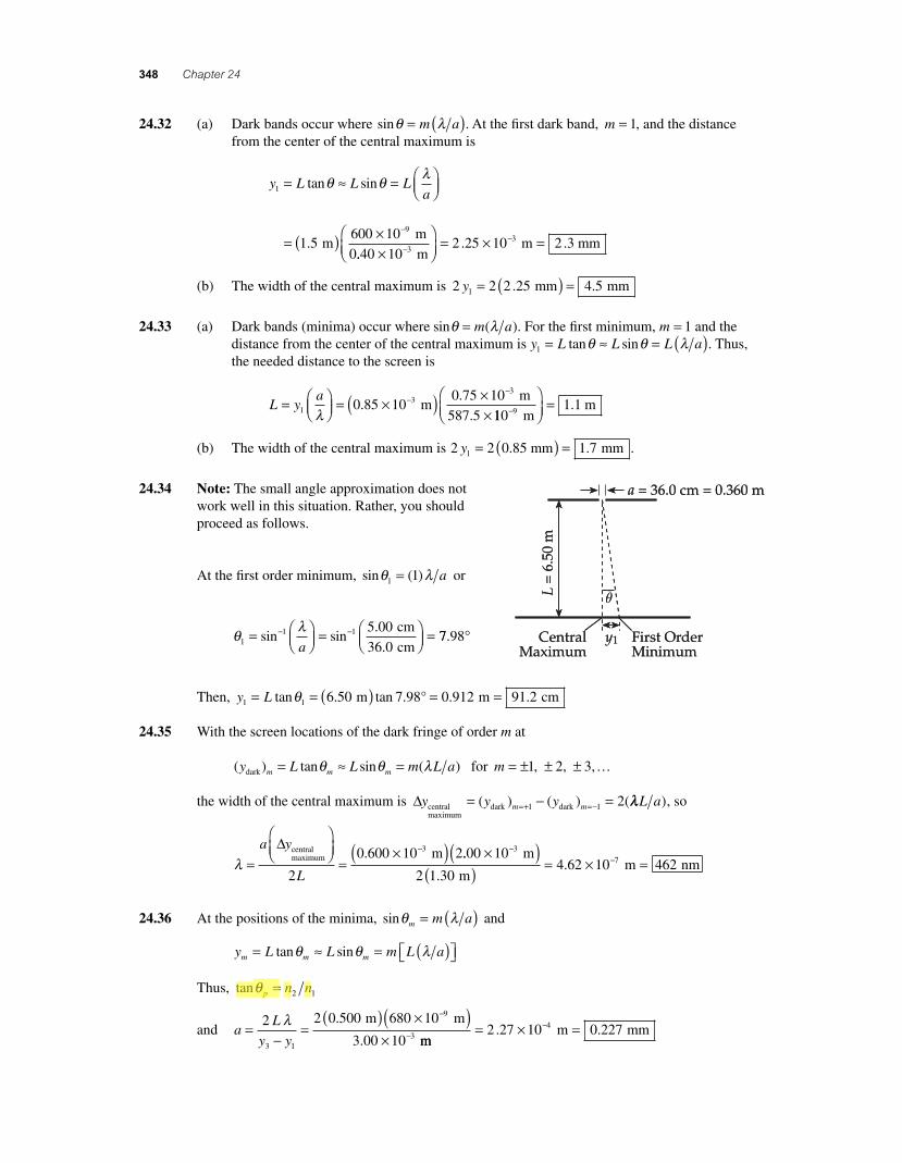
24.34 Note: The small angle approximation does not work well in this situation. Rather, you should proceed as follows.
At the fi rst order minimum, sin ( )θ λ1 1= a or
θ λ
11 1 5 00
36 0= ⎛
⎝⎜⎞⎠⎟ = ⎛
⎝⎜⎞⎠⎟ =− −sin sin
.
.a
cm
cm77 98. °
Then, y L1 1 6 50 7 98 0 912 91 2= = ( ) = =tan . tan . . .θ m m cm°
24.35 With the screen locations of the dark fringe of order m at
( ) tan sin ( )y L L m L am m mdark = ≈ =θ θ λ for m = ± ± ±1, 2, 3,K
the width of the central maximum is Δy y ym mcentralmaximum
dark dark= − ==+ =−( ) ( ) (1 1 2 λλL a), so
λ =
⎛⎝⎜
⎞⎠⎟
=×( )−a y
L
Δ centralmaximum m
2
0 600 10 23. ..
..
00 10
2 1 304 62 10 462
37
×( )( ) = × =
−− m
m m nm
24.36 At the positions of the minima, sinθ λm m a= ( ) and
y L L m L am m m= ≈ = ( )⎡⎣ ⎤⎦tan sinθ θ λ
Thus, tanθ p n n= 2 1
and aL
y y=
−=
( ) ×( )×
−
−
2 2 0 500 680 10
3 00 103 1
9
3
λ .
.
m m
mm m mm= × =−2 27 10 0 2274. .
56157_24_ch24_p335-360.indd 34856157_24_ch24_p335-360.indd 348 3/20/08 1:38:25 AM3/20/08 1:38:25 AM
Comp
Highlight
AU: Please provide replacement of align equation.
Wave Optics 349
24.37 The locations of the dark fringes (minima) mark the edges of the maxima, and the widths of the maxima equals the spacing between successive minima.
At the locations of the minima, sin ( )θ λm m a= and
y L L m L a
m
m m m= ≈ = ( )⎡⎣ ⎤⎦
= ( ) ×
tan sin
.
θ θ λ
1 20500 10
m−−
−×⎛⎝⎜
⎞⎠⎟
⎡
⎣⎢
⎤
⎦⎥ = ( )
9
3101 20
m
0.500 m mmm .
Then, Δ Δy m= ( .1 20 mm) and for successive minima, Δm = 1.
Therefore, the width of each maxima, other than the central maximum, in this interference pattern is
width mm mm= = ( )( ) =Δy 1 1 20 1 20. .
24.38 For diffraction by a grating, the angle at which the maximum of order m occurs is given by d mmsinθ λ= , where d is the spacing between adjacent slits on the grating. Thus,
d
m
m
= =( ) ×( )
°= ×
−λθsin
.
sin ..
1 632 8 10
20 51 81 10
9 m −− =6 1 81 m m. μ
24.39 The grating spacing is d = = ×( ( . )1 3 660 1 3 66 105)cm m and d msinθ λ= .
(a) The wavelength observed in the fi rst-order spectrum is λ θ= d sin , or
λ θ=
×⎛⎝⎜
⎞⎠⎟
⎛⎝⎜
⎞⎠⎟
=1
3 66 10
10 105
9 4 m nm
1 m
.sin
nnm
3.66
⎛⎝⎜
⎞⎠⎟
sinθ
This yields: at 10.1°, λ = 479 nm ; at 13.7°, λ = 647 nm ;
and at 14.8°, λ = 698 nm
(b) In the second order, m = 2. The second order images for the above wavelengths will be found at angles θ λ θ2
1 112 2= ( ) = [ ]− −sin sin sind .
This yields: for λ = 479 nm, θ2 20 5= . ° ; for λ = 647 nm, θ2 28 3= . ° ;
and for λ = 698 nm, θ2 30 7= . °
56157_24_ch24_p335-360.indd 34956157_24_ch24_p335-360.indd 349 3/20/08 4:28:07 AM3/20/08 4:28:07 AM
350 Chapter 24
24.40 (a) The longest wavelength in the visible spectrum is 700 nm, and the grating spacing is d = = × = ×− −1 1 67 10 1 67 103 6mm 600 mm m.. .
Thus, md
max
sin . . sin .= =
×( )−90 0 1 67 10 90 0
700
6° °
λred
m
××=−10
2 389 m.
so 2 complete orders will be observed.
(b) From λ θ= d sin , the angular separation of the red and violet edges in the fi rst order will be
Δθ λ λ
= ⎡⎣⎢
⎤⎦⎥
− ⎡⎣⎢
⎤⎦⎥
=− −sin sin sin1 1red violet
d d−−
−
−−
−××
⎡⎣⎢
⎤⎦⎥
− ×19
61700 10
1 67 10
400 10m
m.sin
99
61 67 10
m
m. ×⎡⎣⎢
⎤⎦⎥−
or Δθ = 10 9. °
24.41 The grating spacing is d = =×
1
4 500
1
4 50 105
cm m
.. From d msinθ λ= , the angular separation
between the given spectral lines will be
Δθ λ λ= ⎡
⎣⎢⎤⎦⎥
− ⎡⎣⎢
⎤⎦⎥
− −sin sin1 1m
d
m
dred violet
or
Δθ =×( ) ×( )⎡
⎣⎢⎢
⎤
⎦⎥⎥
−−−
sin.1
9 5656 10 4 50 10
1
m m
mssin
.−−×( ) ×( )⎡
⎣⎢⎢
⎤
⎦⎥⎥
19 5434 10 4 50 10
1
m m
m
The results obtained are: for m = =1 5 91, . Δθ ° ; for m = =2 13 2, . Δθ ° ;
and for m = =3 26 5, . Δθ ° . Complete orders for m ≥ 4 are not visible.
24.42 (a) If d = = × = ×− −1
1 5006 67 10 6 67 104 6 cm
cm m. . , the highest order of λ = 500 nm that can
be observed will be
md
max
m
m= =
×( )( )×
=−
−
sin .90 6 67 10 1
500 1013
6
9
°
λ..3 or 13 orders
(b) If d = = × = ×− −1
15 0006 67 10 6 67 105 7 cm
cm m. . , then
md
max
m
m= =
×( )( )×
=−
−
sin ..
90 6 67 10 1
500 101
7
9
°
λ333 or 1 order
56157_24_ch24_p335-360.indd 35056157_24_ch24_p335-360.indd 350 3/20/08 1:38:26 AM3/20/08 1:38:26 AM
Wave Optics 351
24.43 The grating spacing is d = = × = ×− −1
5 0002 00 10 2 00 104 6 cm
cm m. . , and d msinθ λ= gives the
angular position of a second order spectral line as
sinθ λ= 2
d or θ λ= ⎛
⎝⎜⎞⎠⎟
−sin 1 2
d
For the given wavelengths, the angular positions are
θ11
9
6
2 610 10
2 00 1037=
×( )×
⎡
⎣⎢⎢
⎤
⎦⎥⎥
=−−
−sin.
m
m..6° and θ2
19
6
2 480 10
2 00 1028=
×( )×
⎡
⎣⎢⎢
⎤
⎦⎥⎥
=−−
−sin.
m
m..7°
If L is the distance from the grating to the screen, the distance on the screen from the central maximum to a second order bright line is y = Ltanq. Therefore, for the two given wavelengths, the screen separation is
Δy L= −[ ]
= ( ) ( ) −
tan tan
. tan . tan .
θ θ1 2
2 00 37 6 28 m ° 77 0 445 44 5°( )⎡⎣ ⎤⎦ = =. . m cm
24.44 With 2 000 lines per centimeter, the grating spacing is
d = = × = ×− −1
2 0005 00 10 5 00 104 6 cm cm m. .
Then, from d msinθ λ= , the location of the fi rst order for the red light is
θ λ= ⎛⎝⎜
⎞⎠⎟ =
×( )×
− −−
−sin sin.
1 191 640 10
5 00 10
m
d
m66 7 35
m
⎛
⎝⎜
⎞
⎠⎟ = . °
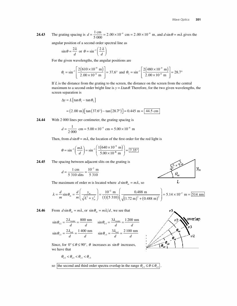
24.45 The spacing between adjacent slits on the grating is
d = =
−1 10 2 cm
5 310 slits
m
5 310
The maximum of order m is located where d mmsinθ λ= , so
λ θ= =
+
⎛
⎝⎜
⎞
⎠⎟ = ( )( )
−d
m
d
m
y
L ym
m
m
sin2 2
210
5 310
0 m
1
..
..
488
0 4885 14 10
2 2
m
1.72 m m( ) + ( )
⎛
⎝⎜⎜
⎞
⎠⎟⎟
= × −− =7 514 m nm
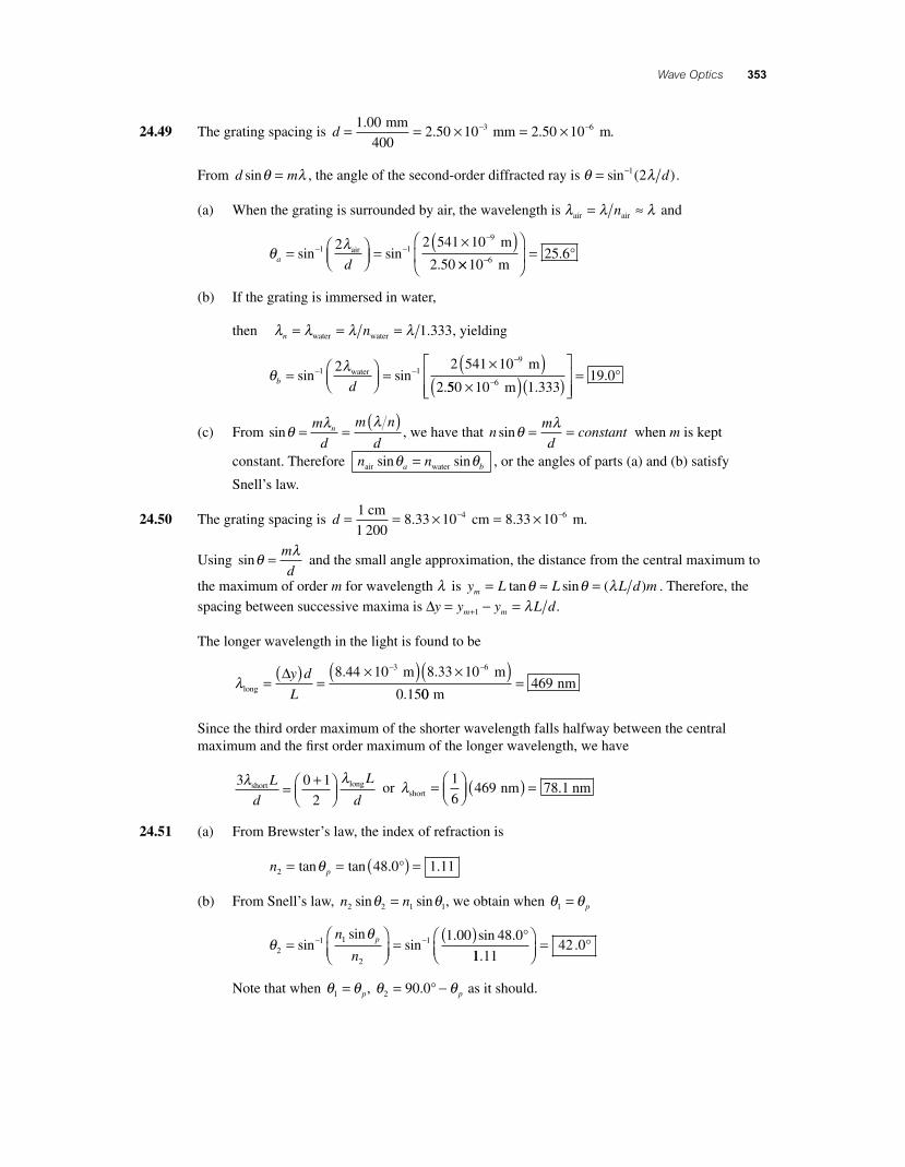
24.46 From d mmsinθ λ= , or sinθ λm m d= , we see that
sinθ λ
v2
2 800= =violet nm
d d sinθ λ
v3
3 1 200= =violet nm
d d
sinθ λ
r d d2
2 1 400= =red nm
sinθ λ
r d d3
3 2 100= =red nm
Since, for 0 90° °≤ ≤θ , θ increases as sinθ increases,we have that
θ θ θ θv v2 3 2 3< < <r r
so the second and third order spectra overlap iin the range θ θ θv3 2≤ ≤ r .
56157_24_ch24_p335-360.indd 35156157_24_ch24_p335-360.indd 351 3/20/08 1:38:27 AM3/20/08 1:38:27 AM

352 Chapter 24
24.47 The grating spacing is d = = = ×−
−1
2 750
10
2 7503 636 10
26 cm m m. . From d msinθ λ= , or
θ λ= ( )−sin 1 m d , the angular positions of the red and violet edges of the second-order spectrum are found to be
θ λr
red m
= ⎛⎝⎜
⎞⎠⎟ =
×( )− −−
sin sin.
1 19
2 2 700 10
3 63d 66 1022 656×
⎛
⎝⎜
⎞
⎠⎟ = °− m
.
and θ λv
violetm
= ⎛⎝⎜
⎞⎠⎟
=×( )− −
−
sin sin1 19
2 2 400 10
3d ...
636 1012 716×
⎛
⎝⎜
⎞
⎠⎟ = °− m
Note from the sketch at the right that y Lr r= tanθand y Lv v= tanθ , so the width of the spectrum on the screen is Δy L= −( )tan tanθ θr v .
Since it is given that Δy = 1.75 cm, the distance from the grating to the screen must be
L
y=−
=( ) −
Δtan tan
.
tan . tan .θ θr
cm
v °
1 75
22 65 12 71°°( )
or L = 9 13. cm
24.48 (a) d =×
= × = ×−1
102 381 10 2 381 14 cm
4.200 slits cm3 . . 00 6− m
(b) d mdmsin sin sinθ λ θ λ= ⇒ = ⎛
⎝⎜⎞⎠⎟ =− − 2
1 12 2 589..
..
0 10
2 381 1029 65
9
6
×( )×
⎡
⎣⎢⎢
⎤
⎦⎥⎥
=−
−
m
m°
(c) y L2 2 2 000 29 65 1 138= = ( ) ( ) =tan . tan . .θ m m°
(d) ′ = ′⎛⎝⎜
⎞⎠⎟ =
×( )− −−
θ λ2
1 19
2 2 589 6 10
2 3sin sin
.
.d
m
881 1029 696×
⎡
⎣⎢⎢
⎤
⎦⎥⎥
=− m. °
′ = ′ = ( ) ( ) =y L2 2 2 000 29 69 1 140tan . tan . .θ m m°
(e) Δy y y= ′ − = − = × −2 2
31 140 1 138 2 10. . m m m
(f) Δy y y Ld
= ′ − = ′⎛⎝⎜
⎞⎠⎟
⎛⎝⎜
⎞⎠⎟
−−2 2
1 2tan sin
λttan sin
. tan
− ⎛⎝⎜
⎞⎠⎟
⎛⎝⎜
⎞⎠⎟
⎡
⎣⎢
⎤
⎦⎥
= ( )
1 2
2 000
λd
m ssin.−
−
−
×( )×
⎛
⎝⎜
⎞
⎠⎟
⎛1
9
2
2 589 6 10
10 10
m
m 4.200 3⎝⎝⎜
⎞
⎠⎟ −
×( )×
−−
−tan sin.
19
2
2 589 0 10
10 1
m
m 4.200 00
1 537 10 3
3
m
⎛
⎝⎜
⎞
⎠⎟
⎛
⎝⎜
⎞
⎠⎟
⎡
⎣⎢⎢
⎤
⎦⎥⎥
= × −.
The two answers agree to only one signifi cant fi gure. The calculation is sensitive to rounding at intermediate steps.
yr
Δy
q rqv
yv
Screen
Grating
L
yr
Δy
q rqv
yv
Screen
Grating
L
56157_24_ch24_p335-360.indd 35256157_24_ch24_p335-360.indd 352 3/20/08 1:38:28 AM3/20/08 1:38:28 AM
Wave Optics 353
24.49 The grating spacing is d = = × = ×− −1 002 50 10 2 50 103 6.. .
mm
400 mm m.
From d msinθ λ= , the angle of the second-order diffracted ray is θ λ= −sin ( )1 2 d .
(a) When the grating is surrounded by air, the wavelength is λ λ λair air= ≈n and
θ λa d
= ⎛⎝⎜
⎞⎠⎟ =
×( )− −−
sin sin.
1 19
2 2 541 10
2 50air
m
××
⎛
⎝⎜
⎞
⎠⎟ =−10
25 66 m. °
(b) If the grating is immersed in water,
then λ λ λ λn n= = =water water 1 333. , yielding
θ λb d
= ⎛⎝⎜
⎞⎠⎟ =
×( )− −−
sin sin.
1 19
2 2 541 10
2water
m
550 10 1 33319 0
6×( )( )⎡
⎣⎢⎢
⎤
⎦⎥⎥
=− m .. °
(c) From sinθ λ λ= =
( )m
d
m n
dn , we have that n
m
dconstantsinθ λ= = when m is kept
constant. Therefore n na bair watersin sinθ θ= , or the angles of parts (a) and (b) satisfy
Snell’s law.
24.50 The grating spacing is d = = × = ×− −1
1 2008 33 10 8 33 104 6 cm
cm m. . .
Using sinθ λ= m
d and the small angle approximation, the distance from the central maximum to
the maximum of order m for wavelength λ is y L L L d mm = ≈ =tan sin ( )θ θ λ . Therefore, the
spacing between successive maxima is Δy y y L dm m= − =+1 λ .
The longer wavelength in the light is found to be
λlong
m m=
( ) =×( ) ×( )− −Δy d
L
8 44 10 8 33 10
0 15
3 6. .
. 00469
m nm=
Since the third order maximum of the shorter wavelength falls halfway between the central maximum and the fi rst order maximum of the longer wavelength, we have
3 0 1
2
λ λshort longL
d
L
d= +⎛
⎝⎜⎞⎠⎟
or λshort nm nm= ⎛⎝⎜
⎞⎠⎟ ( ) =1
6469 78 1.
24.51 (a) From Brewster’s law, the index of refraction is
n p2 48 0 1 11= = ( ) =tan tan . .θ °
(b) From Snell’s law, n n2 2 1 1sin sinθ θ= , we obtain when θ θ1 = p
θθ
21 1
2
1 1 00 48 0=
⎛⎝⎜
⎞⎠⎟
=( )− −sin
sinsin
. sin .n
np °
11 1142 0
..
⎛⎝⎜
⎞⎠⎟
= °
Note that when θ θ1 = p, θ θ2 90 0= −. ° p as it should.
56157_24_ch24_p335-360.indd 35356157_24_ch24_p335-360.indd 353 3/20/08 1:38:29 AM3/20/08 1:38:29 AM
354 Chapter 24
24.52 (a) From Malus’s law, the fraction of the incident intensity of the unpolarized light that is trans-mitted by the polarizer is
′ = ( ) = ( )I I I02
0 0 500cos .θav
The fraction of this intensity incident on the analyzer that will be transmitted is
I I I I= ′ ( ) = ′ ( ) = ( )( ) =cos . . . .2035 0 0 671 0 500 0 671° 00 336 0. I
Thus, the fraction of the incident unpolarized light transmitted is I I0 0 336= . .
(b) The fraction of the original incident light absorbed by the analyzer is
′ − = − =I I
I
I I
I0
0 0
0
0 500 0 3360 164
. ..
24.53 The more general expression for Brewster’s angle is (see Problem 57)
tanθ p n n= 2 1
(a) When n n1 21 00 1 52= =. . and , θ p
n
n=
⎛⎝⎜
⎞⎠⎟
= ⎛⎝⎜
⎞⎠⎟ =− −tan tan
.
..1 2
1
1 1 52
1 0056 7°°
(b) When n n1 21 333 1 52= =. . and , θ p
n
n=
⎛⎝⎜
⎞⎠⎟
= ⎛⎝⎜
⎞⎠⎟ =− −tan tan
.
..1 2
1
1 1 52
1 33348 88°
24.54 The polarizing angle for light in air striking a water surface is
θ p
n
n=
⎛⎝⎜
⎞⎠⎟
= ⎛⎝⎜
⎞⎠⎟ =− −tan tan
.
..1 2
1
1 1 333
1 0053 11°
This is the angle of incidence for the incoming sunlight (that is, the angle between the incident light and the normal to the surface). The altitude of the Sun is the angle between the incident light and the water surface. Thus, the altitude of the Sun is
α θ= − = − ° =90 0 90 0 53 1 36 9. . . .° ° °p
24.55 (a) Brewster’s angle (or the polarizing angle) is
θ p
n
n
n
n=
⎛⎝⎜
⎞⎠⎟
=⎛⎝⎜
⎞⎠⎟
=− −tan tan t1 2
1
1 quartz
air
aan.
..− ⎛
⎝⎞⎠ =1 1 458
1 00055 6°
(b) When the angle of incidence is the polarizing angle, θ p, the angle of refraction of the trans-
mitted light is θ θ2 90 0= −. ° p . Hence,θ2 90 0 55 6 34 4= − =. . .° ° ° .
24.56 The critical angle for total refl ection is θc n n= ( )−sin 12 1 . Thus, if θc = 34 4. ° as light attempts to
go from sapphire into air, the index of refraction of sapphire is
n nn
csapphire = = = =1
2 1 00
34 41 77
sin
.
sin ..
θ °
Then, when light is incident on sapphire from air, the Brewster angle is
θ p
n
n=
⎛⎝⎜
⎞⎠⎟
= ⎛⎝⎜
⎞⎠⎟ =− −tan tan
.
..1 2
1
1 1 77
1 0060 5°°
56157_24_ch24_p335-360.indd 35456157_24_ch24_p335-360.indd 354 3/20/08 5:02:45 AM3/20/08 5:02:45 AM
Wave Optics 355
24.57 From Snell’s law, the angles of incidence and refraction are related by n n1 1 2 2sin sinθ θ= .
If the angle of incidence is the polarizing angle (that is, θ θ1 = p), the refracted ray is perpendicular to the refl ected ray (see Figure 24.28 in the textbook), and the angles of incidence and refraction are also related by
θ θp + + =2 90 180° °, or θ θ2 90= −° p
Substitution into Snell’s law then gives
n n np p p1 2 290sin sin cosθ θ θ= −( ) =° or sin cos tanθ θ θp p p n n= = 2 1
24.58 I I= 02cos θ ⇒ θ =
⎛
⎝⎜⎞
⎠⎟−cos 1
0
I
I
(a) I
I0
1
2 00=
. ⇒ θ =
⎛
⎝⎜⎞⎠⎟
=−cos.
.1 1
2 0045 0°
(b) I
I0
1
4 00=
. ⇒ θ =
⎛
⎝⎜⎞⎠⎟
=−cos.
.1 1
4 0060 0°
(c) I
I0
1
6 00=
. ⇒ θ =
⎛
⎝⎜⎞⎠⎟
=−cos.
.1 1
6 0065 9°
24.59 From Malus’s law, the intensity of the light transmitted by the fi rst polarizer is I Ii12
1= cos θ . The plane of polarization of this light is parallel to the axis of the fi rst plate and is incident on the second plate. Malus’s law gives the intensity transmitted by the second plate as I I Ii2 1
22 1
21
22 1= −( ) = −( )cos cos cosθ θ θ θ θ . This light is polarized parallel to the axis of
the second plate and is incident upon the third plate. A fi nal application of Malus’s law gives the transmitted intensity as
I I If i= −( ) = −( ) −22
3 22
12
2 12
3cos cos cos cosθ θ θ θ θ θ θθ2( )
With θ θ θ1 2 320 0 40 0 60 0= = =. . .° ° °, , and , this result yields
I f = ( ) ( ) ( )10 0 20 0 20 0 202 2 2. cos . cos . cos units ° ° .. .0 6 89°( ) = units
24.60 (a) Using Malus’s law, the intensity of the transmitted light is found to be
I I I= ( ) = ( )02
0
245 1 2cos ° , or I I0 1 2=
(b) From Malus’s law, I I02= cos θ . Thus, if I I0 1 3= we obtain
cos2 1 3θ = or θ = ( ) =−cos .1 1 3 54 7°
24.61 (a) If light has wavelength λ in vacuum, its wavelength in a medium of refractive index n is λ λn n= . Thus, the wavelengths of the two components in the specimen are
λ λn n1
1
546 1413 7= = =.
. nm
1.320 nm
and λ λn n2
2
546 1409 7= = =.
. nm
1.333 nm
continued on next page
56157_24_ch24_p335-360.indd 35556157_24_ch24_p335-360.indd 355 3/20/08 1:38:30 AM3/20/08 1:38:30 AM
356 Chapter 24
(b) The number of cycles of vibration each component completes while passing through the specimen are
Nt
n1
14
2 417= = ××
=−
−λ1.000 10 m
13.7 10 m
6
9 .
and Nt
n2
24 9
2 441= = ××
=−
−λ1.000 10 m
0 .7 10 m
6
9 .
Thus, when they emerge, the two components are out of phase by N N2 1 0 024− = . cycles. Since each cycle represents a phase angle of 360°, they emerge with a phase difference of
Δφ = ( )( ) =0 024 360 8 6. . cycles cycle° °
24.62 In a single slit diffraction pattern, the fi rst dark fringe occurs where sin( )θ λdark 1 1= ( ) a. If no diffraction minima are to be observed, it is necessary that no real solutions exist for this equation defi ning the location of the fi rst minimum. Thus, it is necessary that sin( ) .θ λdark 1 1 1 00= ( ) >a , or λ a > 1 00. and a < λ. We then see that the maximum width the slit can have before this con-dition will fail and diffraction minima will start being visible is amax . .= =λ 632 8 nm
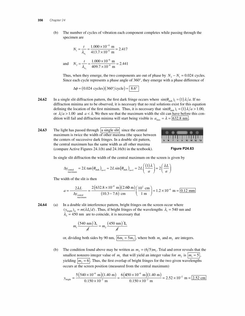
24.63 The light has passed through a single slit since the central maximum is twice the width of other maxima (the space between the centers of successive dark fringes. In a double slit pattern, the central maximum has the same width as all other maxima (compare Active Figures 24.1(b) and 24.16(b) in the textbook). Figure P24.63
In single slit diffraction the width of the central maximum on the screen is given by
Δy L Lmcentral
maximumdark dark= ( ) ≈=2 2
1tan sinθ θ(( ) =
( )⎛⎝⎜
⎞⎠⎟
= ⎛⎝⎜
⎞⎠⎟=m
La
L
a12
12
λ λ
The width of the slit is then
aL
y= =
×( )−2 2 632 8 10 2 69λ
m
centralmaximum
Δ. . 00
10 3 7 6
101 2 10
24
m
cm
cm
1 m
( )−( )
⎛⎝⎜
⎞⎠⎟
= × −
. .. m mm= 0 12.
24.64 (a) In a double slit interference pattern, bright fringes on the screen occur where ( ) ( )y m L dmbright = λ . Thus, if bright fringes of the wavelengths λ1 540= nm and λ2 450= nm are to coincide, it is necessary that
mL
dm
L
d1 2
540 450 nm nm( ) =( )
or, dividing both sides by 90 nm, 6 51 2m m= , where both m m1 2 and are integers.
(b) The condition found above may be written as m m2 16 5= ( ) . Trial and error reveals that the
smallest nonzero integer value of m1 that will yield an integer value for m2 is m1 5= ,
yielding m2 6= . Thus, the fi rst overlap of bright fringes for the two given wavelengths
occurs at the screen position (measured from the central maximum)
ybright
m m
m=
×( )( )×
=−
−
5 540 10 1 40
0 150 10
69
3
.
.
4450 10 1 40
0 150 102 52 10
9
32
×( )( )×
= ×−
−− m m
m
.
.. m cm= 2 52.
56157_24_ch24_p335-360.indd 35656157_24_ch24_p335-360.indd 356 3/20/08 4:52:04 AM3/20/08 4:52:04 AM
Wave Optics 357
24.65 Dark fringes (destructive interference) occur where d msinθ λ= +( )1 2 for m = …0 1 2, , , . Thus, if the second dark fringe m =( )1 occurs at
θ = ( )⎛⎝⎜
⎞⎠⎟ = °18 0
1 00
60 00 300.
.
.. min
min
°,
the slit spacing is
d m= +⎛⎝⎜
⎞⎠⎟ = ⎛
⎝⎜⎞⎠⎟
×( )−1
2
3
2
546 10
0
9λθsin sin .
m
33001 56 10 0 1564
°( ) = × =−. . m mm
24.66 The wavelength is λ = = =vsound m s
2 000 Hz m
f
3400 170. .
Maxima occur where d msinθ λ= , or θ λ= ( )⎡⎣ ⎤⎦−sin 1 m d for m = …0 1 2, , , .
Since d = 0 350. m, λ d = 0 486. , which gives θ = ( )−sin .1 0 486 m .
For m = 0 1 2, , and , this yields maxima at 0 , 29.1 , and 76.3° ° ° .
No solutions exist for m ≥ 3 since that would imply sinθ > 1.
Minima occur where d msinθ λ= +( )1 2 or θ λ= +( )⎡
⎣⎢
⎤
⎦⎥
−sin 1 2 12
md
for m = 0 1 2, , ,K.
With λ d = 0 486. , this becomes θ = +( )( )⎡⎣ ⎤⎦−sin .1 2 1 0 243m .
For m = 0 1 and , we fi nd minima at 4.1 and 46.81 ° ° .
No solutions exist for m ≥ 2 since that would imply sinθ > 1.
24.67 The source and its image, located 1.00 cm below the mirror, act as a pair of coherent sources. This situation may be treated as double-slit interference, with the slits separated by 2.00 cm, if it is remembered that the light undergoes a phase reversal upon refl ection from the mirror. The existence of this phase change causes the conditions for constructive and destructive interference to be reversed. Therefore, dark bands (destructive interference) occur where
y m L d= ( )λ for m = …0 1 2, , ,
The m = 0 dark band occurs at y = 0 (that is, at mirror level). The fi rst dark band above the mirror corresponds to m = 1 and is located at
yL
d= ( )⎛
⎝⎜⎞⎠⎟ =
×( )( )×
−
−1500 10 100
2 00 10
9
2
λ m m
. m m mm= × =−2 50 10 2 503. .
56157_24_ch24_p335-360.indd 35756157_24_ch24_p335-360.indd 357 3/20/08 1:38:32 AM3/20/08 1:38:32 AM

358 Chapter 24
24.68 Assuming the glass plates have refractive indices greater than that of both air and water, there will be a phase reversal at the refl ection from the lower surface of the fi lm but no reversal from refl ection at the top of the fi lm. Therefore, the condition for a dark fringe is
2 t m m nn= = ( )λ λ film for m = …0 1 2, , ,
If the highest order dark band observed is m = 84 (a total of 85 dark bands counting the m = 0 order at the edge of contact), the maximum thickness of the wedge is
tm
nmaxmax
film 1.00=
⎛⎝⎜
⎞⎠⎟
= ⎛⎝⎜
⎞⎠⎟ =
2
84
242
λ λ λ
When the fi lm consists of water, the highest order dark fringe appearing will be
m tn
max maxfilm 1.333= ⎛
⎝⎜⎞⎠⎟ = ( )⎛
⎝⎜⎞⎠⎟ =2 2 42 1
λλ
λ112
Counting the m = 0 order, a total of 113 dark fringes are now observed.
24.69 In the fi gure at the right, observe that the path difference between the direct and the indirect paths is
δ = − = + ( ) −2 2 22 2x d h d d
With a phase reversal (equivalent to a half-wavelength shift) occurring on the refl ection at the ground, the condition for constructive interference is δ λ= +( )m 1 2 , and the condition for destructive interference is δ λ= m . In both cases, the possible values of the order number are m = …0 1 2, , , .
(a) The wavelengths that will interfere constructively are λ δ=+m 1 2
. The longest of these is for the m = 0 case and has a value of
λ δ= = + ( ) −
= ( ) + ( ) −
2 4 2 2
4 50 0 300 2 600
2 2
2 2
h d d
. m m mm m( ) = 16 6.
(b) The wavelengths that will interfere destructively are λ δ= m, and the largest fi nite one of these is for the m = 1 case. That wavelength is
λ δ= = + ( ) − = ( ) + ( ) − =2 2 2 50 0 300 600 82 2 2 2h d d . m m m ..28 m
24.70 From Malus’s law, the intensity of the light transmitted by the fi rst polarizer is I Ii12
1= cos θ . The plane of polarization of this light is parallel to the axis of the fi rst plate and is inci-dent on the second plate. Malus’s law gives the intensity transmitted by the second plate as
I I Ii2 12
2 12
12
2 1= −( ) = −( )cos cos cosθ θ θ θ θ . This light is polarized parallel to the axis of the second plate and is incident upon the third plate. A fi nal application of Malus’s law gives the transmitted intensity as
I I If i= −( ) = −( ) −22
3 22
12
2 12
3cos cos cos cosθ θ θ θ θ θ θθ2( )
continued on next page
56157_24_ch24_p335-360.indd 35856157_24_ch24_p335-360.indd 358 3/20/08 1:38:33 AM3/20/08 1:38:33 AM
Wave Optics 359
(a) If θ θ θ1 2 345 90 0= = =° ° °, , and , then
I If i = −( ) −( ) =cos cos cos2 2 245 90 45 0 90 0° ° ° ° °
(b) If θ θ θ1 2 30 45 90= = =° ° °, , and , then
I If i = −( ) −( ) =cos cos cos .2 2 20 45 0 90 45 0 25° ° ° ° °
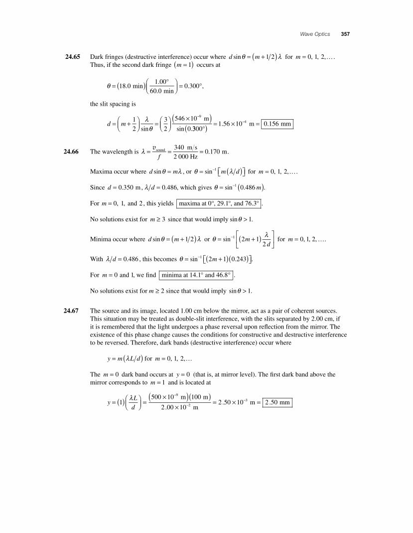
24.71 If the signal from the antenna to the receiver station is to be completely polarized by refl ection from the water, the angle of incidence where it strikes the water must equal the polarizing angle from Brewster’s law. This is given by
θ p
n
n=
⎛⎝⎜
⎞⎠⎟
= ( ) = °− −tan tan . .1 1 1 33 53 1water
air
From the triangle RST in the sketch, thehorizontal distance from the point of refection, T, to shore is given by
x p= ( ) = ( )( ) =90 0 90 0 1 33 120. tan . . m m mθ
and from triangle ABT, the horizontal distance from the antenna to this point is
y p= ( ) = ( )( ) =5 00 5 00 1 33 6 65. tan . . . m m mθ
The total horizontal distance from ship to shore is then x y+ = + =120 6 65 127 m m m. .
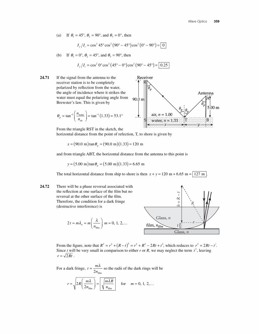
24.72 There will be a phase reversal associated with the refl ection at one surface of the fi lm but no reversal at the other surface of the fi lm. Therefore, the condition for a dark fringe (destructive interference) is
2 t m mnn= =
⎛⎝⎜
⎞⎠⎟
λ λfilm
m = …0 1 2, , ,
From the fi gure, note that R r R t r R Rt t2 2 2 2 2 22= + −( ) = + − + , which reduces to r Rt t2 22= − . Since t will be very small in comparison to either r or R, we may neglect the term t 2 , leaving r Rt≈ 2 .
For a dark fringe, tm
n= λ
2 film
so the radii of the dark rings will be
r Rm
n
m R
n≈
⎛⎝⎜
⎞⎠⎟
=22
λ λfilm film
for m = …0 1 2, , ,
56157_24_ch24_p335-360.indd 35956157_24_ch24_p335-360.indd 359 3/20/08 1:38:34 AM3/20/08 1:38:34 AM

360 Chapter 24
24.73 In the single slit diffraction pattern, destructive interference (or minima) occur where sinθ λ= ( )m a for m = ± ± …0 1 2, , , . The screen locations, measured from the center of the central maximum, of these minima are at
y L L m L am m m= ≈ = ( )tan sinθ θ λ
If we assume the fi rst-order maximum is halfway between the fi rst- and second-order minima, then its location is
yy y L a L
a= + =
+( )( )=1 2
2
1 2
2
3
2
λ λ
and the slit width is
aL
y= =
×( )( )×( )
−
−
3
2
3 500 10 1 40
10
9
3
λ m m
2 3.00 m
.== × =−3 50 10 0 3504. . m mm
24.74 As light emerging from the glass refl ects from the top of the air layer, there is no phase reversal produced. However, the light refl ecting from the end of the metal rod at the bottom of the air layer does experience phase reversal. Thus, the condition for constructive interference in the refl ected light is 2 1
2t m= +( )λair .
As the metal rod expands, the thickness of the air layer decreases. The increase in the length of the rod is given by
Δ Δ ΔL t m m mi f= = +( ) − +( ) =12
122 2 2
λ λ λair air air
The order number changes by one each time the fi lm changes from bright to dark and back to bright. Thus, during the expansion, the measured change in the length of the rod is
ΔL = ( ) = ( ) ×( )= ×
−−200
2200
500 10
25 00 10
95λair
m . mm
From Δ ΔL L T= ( )0α , the coeffi cient of linear expansion of the rod is
α = ( ) = ×( )( ) =
−ΔΔL
L T0
55 00 10
0 100 25 020
.
. ..
m
m C°00 10 6× ( )− −
C1
°
56157_24_ch24_p335-360.indd 36056157_24_ch24_p335-360.indd 360 3/20/08 1:38:35 AM3/20/08 1:38:35 AM