5.3 Electricity - Resistivity 1 - Qs · characteristic for the filament lamp ... The resistor and...
35
Page 1 of 35 5.3 Electricity - Resistivity 1 – Questions Q1. State what is meant by a superconductor. _______________________________________________________________________ _______________________________________________________________________ (Total 1 mark) Q2. A teacher wishes to construct a 2.0 Ω resistor from a metal wire of length 0.94 m. The metal wire has an electrical resistivity of 4.9 × 10 –7 Ω m. Calculate the required diameter of the wire. _______________________________________________________________________ _______________________________________________________________________ _______________________________________________________________________ _______________________________________________________________________ _______________________________________________________________________ diameter ____________________ mm (Total 4 marks) Q3. The diagram below shows the circuit for a small convector heater. Heater elements can be switched in and out of the circuit using switches X and Y. Each element has a resistance R and the power supply has an emf V. (a) The table shows the possible combinations of open and closed switches. When a switch is closed, charge can flow through it. Complete the table. Assume that the internal resistance of the power supply is
Transcript of 5.3 Electricity - Resistivity 1 - Qs · characteristic for the filament lamp ... The resistor and...
Page 1 of 35
5.3 Electricity - Resistivity 1 – Questions
Q1. State what is meant by a superconductor.
_______________________________________________________________________
_______________________________________________________________________ (Total 1 mark)
Q2. A teacher wishes to construct a 2.0 Ω resistor from a metal wire of length 0.94 m. The metal wire has an electrical resistivity of 4.9 × 10⁻⁷ Ω m. Calculate the required diameter of the wire.
_______________________________________________________________________
_______________________________________________________________________
_______________________________________________________________________
_______________________________________________________________________
_______________________________________________________________________
diameter ____________________ mm (Total 4 marks)
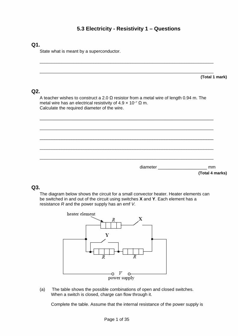
Q3. The diagram below shows the circuit for a small convector heater. Heater elements can be switched in and out of the circuit using switches X and Y. Each element has a resistance R and the power supply has an emf V.
(a) The table shows the possible combinations of open and closed switches. When a switch is closed, charge can flow through it.
Complete the table. Assume that the internal resistance of the power supply is
Page 2 of 35
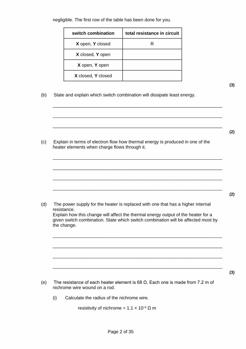
negligible. The first row of the table has been done for you.
switch combination total resistance in circuit
X open, Y closed R
X closed, Y open
X open, Y open
X closed, Y closed
(3)
(b) State and explain which switch combination will dissipate least energy.
___________________________________________________________________
___________________________________________________________________
___________________________________________________________________ (2)
(c) Explain in terms of electron flow how thermal energy is produced in one of the heater elements when charge flows through it.
___________________________________________________________________
___________________________________________________________________
___________________________________________________________________
___________________________________________________________________ (2)
(d) The power supply for the heater is replaced with one that has a higher internal resistance. Explain how this change will affect the thermal energy output of the heater for a given switch combination. State which switch combination will be affected most by the change.
___________________________________________________________________
___________________________________________________________________
___________________________________________________________________
___________________________________________________________________ (3)
(e) The resistance of each heater element is 68 Ω. Each one is made from 7.2 m of nichrome wire wound on a rod.
(i) Calculate the radius of the nichrome wire.
resistivity of nichrome = 1.1 × 10⁻⁶ Ω m
Page 3 of 35
radius ____________________ m (2)
(ii) Suggest two properties that the rod must have to make it suitable in this application.
______________________________________________________________
______________________________________________________________
______________________________________________________________ (2)
(Total 14 marks)
Q4. (a) State what is meant by a superconducting material.
___________________________________________________________________
___________________________________________________________________
___________________________________________________________________
___________________________________________________________________ (2)
(b) State an application of a superconductor and explain why it is useful in this application.
___________________________________________________________________
___________________________________________________________________
___________________________________________________________________
___________________________________________________________________ (2)
(Total 4 marks)
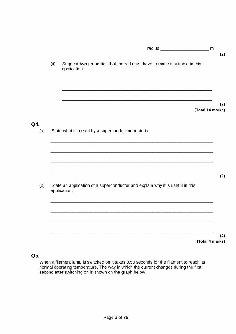
Q5. When a filament lamp is switched on it takes 0.50 seconds for the filament to reach its normal operating temperature. The way in which the current changes during the first second after switching on is shown on the graph below.
Page 4 of 35
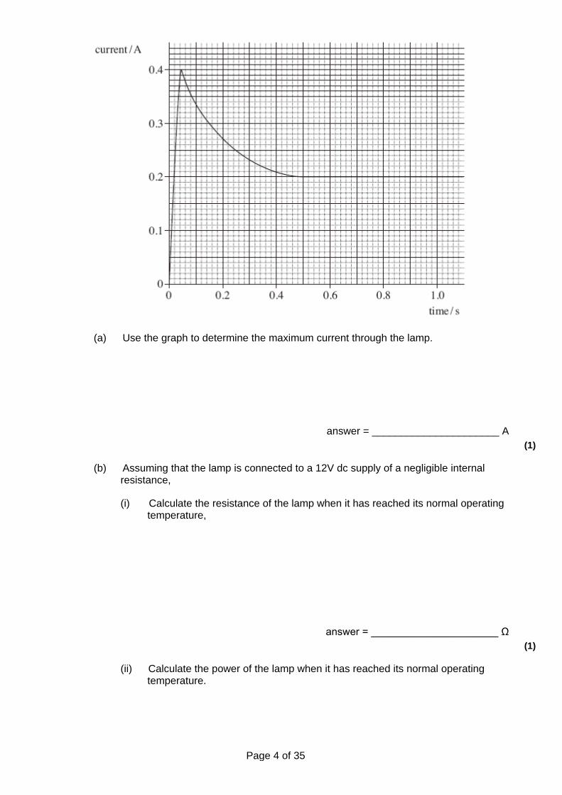
(a) Use the graph to determine the maximum current through the lamp.
answer = ______________________ A (1)
(b) Assuming that the lamp is connected to a 12V dc supply of a negligible internal resistance,
(i) Calculate the resistance of the lamp when it has reached its normal operating temperature,
answer = ______________________ Ω (1)
(ii) Calculate the power of the lamp when it has reached its normal operating temperature.
Page 5 of 35
answer = ______________________ W (1)
(c) Explain why the current through the lamp decreases between 0.05 s and 0.50 s.
___________________________________________________________________
___________________________________________________________________
___________________________________________________________________
___________________________________________________________________
___________________________________________________________________
___________________________________________________________________ (2)
(d) State and explain the change, if any, to the final current through the lamp if it is connected to the same supply with another similar lamp
(i) in series,
______________________________________________________________
______________________________________________________________
______________________________________________________________
______________________________________________________________ (2)
(ii) in parallel.
______________________________________________________________
______________________________________________________________
______________________________________________________________
______________________________________________________________ (2)
(e) State and explain why a filament lamp is most likely to fail as it is switched on.
___________________________________________________________________
___________________________________________________________________
___________________________________________________________________
___________________________________________________________________ (2)
Page 6 of 35
(Total 11 marks)
Q6. (a) A sample of conducting putty is rolled into a cylinder which is 6.0 × 10⁻² m long and
has a radius of 1.2 × 10⁻² m.
resistivity of the putty = 4.0 × 10⁻³ Ωm.
Calculate the resistance between the ends of the cylinder of conducting putty. Your answer should be given to an appropriate number of significant figures.
answer = ____________________ Ω (4)
(b) Given the original cylinder of the conducting putty described in part (a), describe how you would use a voltmeter, ammeter and other standard laboratory equipment to determine a value for the resistivity of the putty.
Your description should include
• a labelled circuit diagram, • details of the measurements you would make, • an account of how you would use your measurements to determine the result, • details of how to improve the precision of your measurements.
The quality of your written communication will be assessed in this question.
___________________________________________________________________
___________________________________________________________________
___________________________________________________________________
Page 7 of 35
___________________________________________________________________
___________________________________________________________________
___________________________________________________________________
___________________________________________________________________
___________________________________________________________________
___________________________________________________________________
___________________________________________________________________ (8)
(Total 12 marks)
Q7. A copper connecting wire is 0.75 m long and has a cross-sectional area of 1.3 × 10⁻⁷ m2.
(a) Calculate the resistance of the wire.
resistivity of copper = 1.7 × 10⁻⁷ Ωm
resistance = ____________________ Ω (2)
(b) A 12 V 25 W lamp is connected to a power supply of negligible internal resistance using two of the connecting wires. The lamp is operating at its rated power.
(i) Calculate the current flowing in the lamp.
current = ____________________ A (1)
(ii) Calculate the pd across each of the wires.
pd = ____________________ V (1)
(iii) Calculate the emf (electromotive force) of the power supply.
Page 8 of 35
emf = ____________________ V (2)
(c) The lamp used in part (b) is connected by the same two wires to a power supply of the same emf but whose internal resistance is not negligible.
State and explain what happens to the brightness of the lamp when compared to its brightness in part (b).
___________________________________________________________________
___________________________________________________________________
___________________________________________________________________
___________________________________________________________________
___________________________________________________________________
___________________________________________________________________ (2)
(Total 8 marks)
Q8. (a) A constantan wire has a radius of 0.430 mm and a resistance of 5.60 Ω.
The resistivity of constantan is 4.90 x 10⁻⁷ Ωm.
Calculate the length of the wire in m.
___________________________________________________________________
___________________________________________________________________
___________________________________________________________________
___________________________________________________________________
___________________________________________________________________
___________________________________________________________________
length ______________________ m (3)
(b) A wire of resistance 5.60 Ω is connected across the terminal of a cell. The cell has an emf of 1.50 V and an internal resistance of r.
(i) The current through the wire is 0.247 A. Calculate the total resistance of the circuit.
______________________________________________________________
Page 9 of 35
______________________________________________________________
______________________________________________________________
______________________________________________________________
resistance ______________________ Ω (2)
(ii) Determine the internal resistance, r, of the cell.
______________________________________________________________
______________________________________________________________
resistance ______________________ Ω (1)
(Total 6 marks)
Q9. (a) The rating of a car headlamp is 12 V, 55 W.
The resistance in this headlamp is due to a thin piece of wire. At its working temperature, the wire has a length of 5.0 × 10⁻² m and a cross-sectional area of 1.9 × 10⁻⁸ m2. Calculate, at the working temperature, the resistivity of the metal used to make the wire. State an appropriate unit for your answer.
resistivity ______________________unit ___________ (5)
(b) (i) Define the term electromotive force (emf).
______________________________________________________________
______________________________________________________________
______________________________________________________________
______________________________________________________________ (2)
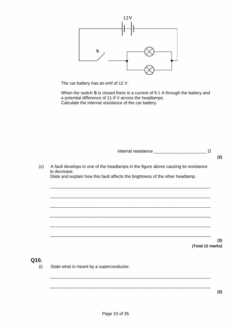
(ii) The figure below is a circuit diagram illustrating how two of these headlamps are connected to a car battery.
Page 10 of 35
The car battery has an emf of 12 V.
When the switch S is closed there is a current of 9.1 A through the battery and a potential difference of 11.9 V across the headlamps. Calculate the internal resistance of the car battery.
internal resistance ______________________ Ω (2)
(c) A fault develops in one of the headlamps in the figure above causing its resistance to decrease. State and explain how this fault affects the brightness of the other headlamp.
___________________________________________________________________
___________________________________________________________________
___________________________________________________________________
___________________________________________________________________
___________________________________________________________________
___________________________________________________________________ (3)
(Total 12 marks)
Q10. (i) State what is meant by a superconductor.
___________________________________________________________________
___________________________________________________________________ (2)
Page 11 of 35
(ii) With reference to two uses for superconductors in today’s world, explain the advantage of their use compared with conventional conductors such as copper.
___________________________________________________________________
___________________________________________________________________
___________________________________________________________________
___________________________________________________________________
___________________________________________________________________
___________________________________________________________________ (3)
(Total 5 marks)
Q11. At room temperature a metal has a resistivity of 4.5 × 10⁻⁷ Ωm. A wire made from this metal has a radius of 0.70 mm.
(a) (i) Calculate the resistance of a 2.5 m length of the wire at room temperature.
resistance ____________________Ω (3)
(ii) Calculate the power dissipated in this length of wire when it carries a current of 20 mA. Assume the resistance of the wire is constant.
power ____________________W (2)
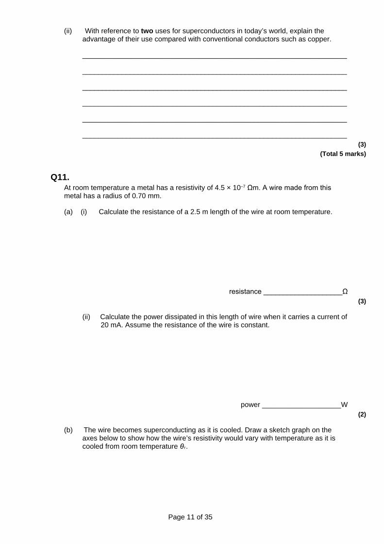
(b) The wire becomes superconducting as it is cooled. Draw a sketch graph on the axes below to show how the wire’s resistivity would vary with temperature as it is cooled from room temperature θr.
Page 12 of 35
(3)
(c) Explain why the efficiency of electrical power transmission is improved when conventional wires are replaced with superconducting wires.
___________________________________________________________________
___________________________________________________________________
___________________________________________________________________ (1)
(Total 9 marks)
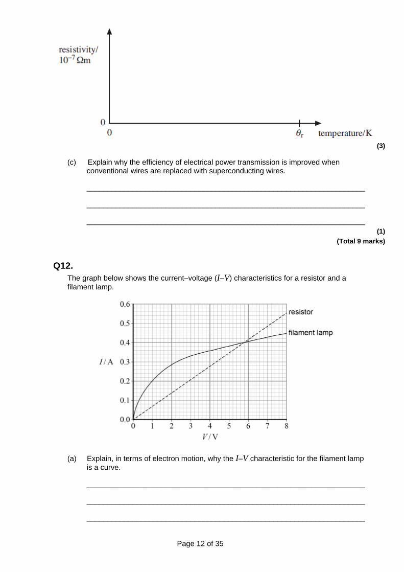
Q12. The graph below shows the current–voltage (I–V) characteristics for a resistor and a filament lamp.
(a) Explain, in terms of electron motion, why the I–V characteristic for the filament lamp is a curve.
___________________________________________________________________
___________________________________________________________________
___________________________________________________________________

Page 13 of 35
___________________________________________________________________
___________________________________________________________________
___________________________________________________________________
___________________________________________________________________
___________________________________________________________________
___________________________________________________________________
___________________________________________________________________ (4)
(b) Determine the resistance of the resistor.
resistance = ____________________ Ω (1)
(c) The resistor and the filament lamp are connected in series with a supply of variable emf and negligible internal resistance.
Determine the emf that produces a current of 0.18 A in the circuit.
emf = ____________________ V (3)
(d) The resistor and filament lamp are now connected in parallel.
Determine the resistance of the parallel combination when the emf of the supply is adjusted to be 4.0 V.
resistance = ____________________ Ω (3)
(e) The resistance of the filament lamp at its working temperature is 14 Ω.
The filament has a length of 0.36 m and a diameter of 32 µm.
Calculate the resistivity of the metal that is used for the filament when the lamp is at its working temperature.
Page 14 of 35
Give an appropriate unit for your answer.
resistivity = ____________________ unit ___________ (3)
(Total 14 marks)
Q13. The critical temperature of tin is −269 °C. The resistivity of tin increases as its temperature rises from −269 °C.
(a) (i) Define resistivity.
______________________________________________________________
______________________________________________________________
______________________________________________________________
______________________________________________________________ (2)
(ii) State the significance of the critical temperature of a material.
______________________________________________________________
______________________________________________________________
______________________________________________________________
______________________________________________________________ (2)
(b) A sample of tin in the form of a cylinder of diameter 1.0 mm and length 4.8 m has a resistance of 0.70 Ω.
Use these data to calculate a value of the resistivity of tin. State an appropriate unit for your answer.
Page 15 of 35
resistivity ____________________ unit __________ (4)
(Total 8 marks)
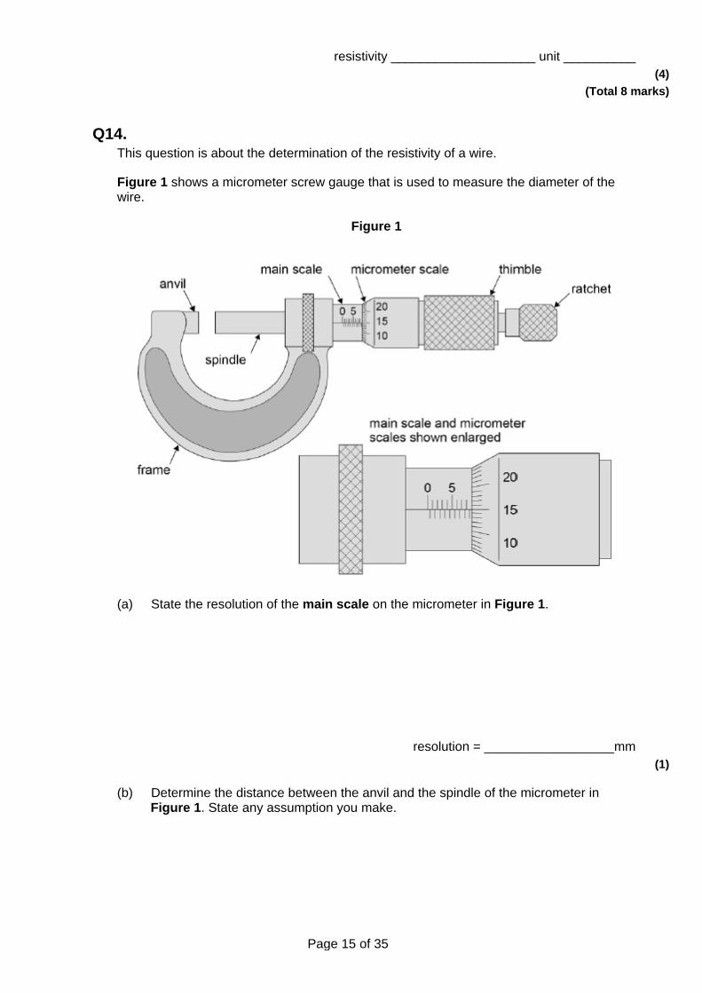
Q14. This question is about the determination of the resistivity of a wire.
Figure 1 shows a micrometer screw gauge that is used to measure the diameter of the wire.
Figure 1
(a) State the resolution of the main scale on the micrometer in Figure 1.
resolution = __________________mm (1)
(b) Determine the distance between the anvil and the spindle of the micrometer in Figure 1. State any assumption you make.
Page 16 of 35
distance = ___________________mm (2)
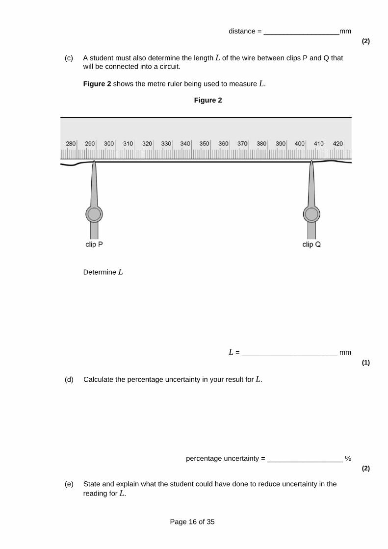
(c) A student must also determine the length L of the wire between clips P and Q that will be connected into a circuit.
Figure 2 shows the metre ruler being used to measure L.
Figure 2
Determine L
L = ________________________ mm (1)
(d) Calculate the percentage uncertainty in your result for L.
percentage uncertainty = ___________________ % (2)
(e) State and explain what the student could have done to reduce uncertainty in the reading for L.
Page 17 of 35
___________________________________________________________________
___________________________________________________________________
___________________________________________________________________ (1)
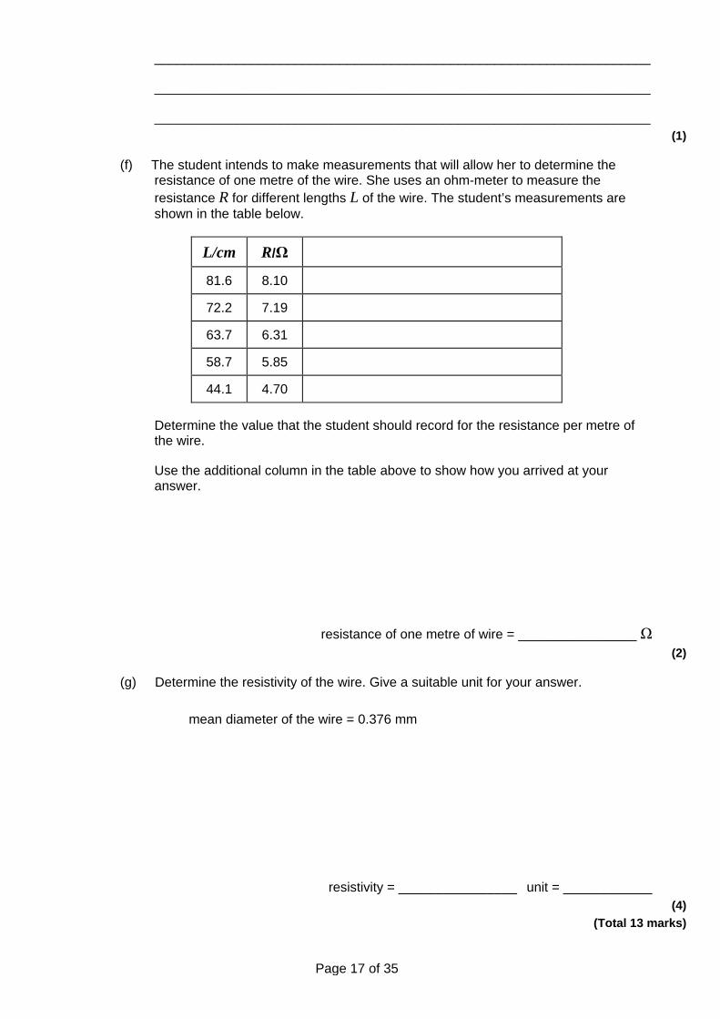
(f) The student intends to make measurements that will allow her to determine the resistance of one metre of the wire. She uses an ohm-meter to measure the resistance R for different lengths L of the wire. The student’s measurements are shown in the table below.
L/cm R/Ω
81.6 8.10
72.2 7.19
63.7 6.31
58.7 5.85
44.1 4.70
Determine the value that the student should record for the resistance per metre of the wire.
Use the additional column in the table above to show how you arrived at your answer.
resistance of one metre of wire = ________________ Ω (2)
(g) Determine the resistivity of the wire. Give a suitable unit for your answer.
mean diameter of the wire = 0.376 mm
resistivity = ________________ unit = ____________ (4)
(Total 13 marks)
Page 18 of 35
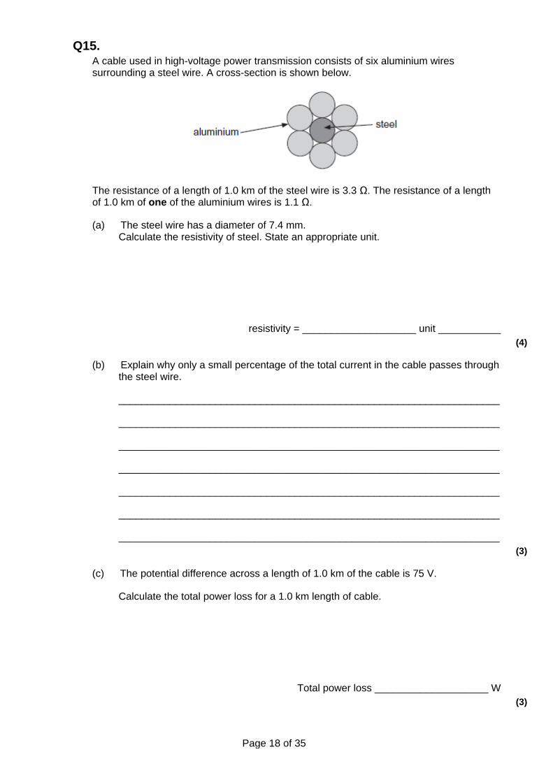
Q15. A cable used in high-voltage power transmission consists of six aluminium wires surrounding a steel wire. A cross-section is shown below.
The resistance of a length of 1.0 km of the steel wire is 3.3 Ω. The resistance of a length of 1.0 km of one of the aluminium wires is 1.1 Ω.
(a) The steel wire has a diameter of 7.4 mm. Calculate the resistivity of steel. State an appropriate unit.
resistivity = ____________________ unit ___________ (4)
(b) Explain why only a small percentage of the total current in the cable passes through the steel wire.
___________________________________________________________________
___________________________________________________________________
___________________________________________________________________
___________________________________________________________________
___________________________________________________________________
___________________________________________________________________
___________________________________________________________________ (3)
(c) The potential difference across a length of 1.0 km of the cable is 75 V.
Calculate the total power loss for a 1.0 km length of cable.
Total power loss ____________________ W (3)
Page 19 of 35
(Total 10 marks)
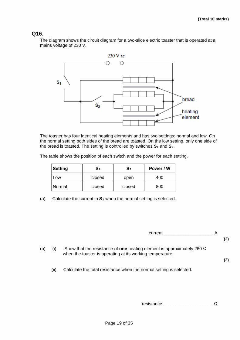
Q16. The diagram shows the circuit diagram for a two-slice electric toaster that is operated at a mains voltage of 230 V.
The toaster has four identical heating elements and has two settings: normal and low. On the normal setting both sides of the bread are toasted. On the low setting, only one side of the bread is toasted. The setting is controlled by switches S1 and S2.
The table shows the position of each switch and the power for each setting.
Setting S1 S2 Power / W
Low closed open 400
Normal closed closed 800
(a) Calculate the current in S2 when the normal setting is selected.
current ____________________ A (2)
(b) (i) Show that the resistance of one heating element is approximately 260 Ω when the toaster is operating at its working temperature.
(2)
(ii) Calculate the total resistance when the normal setting is selected.
resistance ____________________ Ω
Page 20 of 35
(2)
(iii) Each heating element is made of nichrome wire of diameter 0.15 mm. The nichrome wire is wrapped around an insulating board.
Determine the length of nichrome wire needed to provide a resistance of 260 Ω.
resistivity of nichrome at the working temperature = 1.1 × 10⁻⁶ Ω m
length of wire ____________________ m (3)
(c) Explain why the resistivity of the nichrome wire changes with temperature.
___________________________________________________________________
___________________________________________________________________
___________________________________________________________________
___________________________________________________________________
___________________________________________________________________ (3)
(d) The nichrome wire has an equilibrium temperature of 174°C when the toaster is operating.
Calculate the peak wavelength of the electromagnetic radiation emitted by the wire.
Give your answer to an appropriate number of significant figures.
peak wavelength ____________________ m (3)
(Total 15 marks)
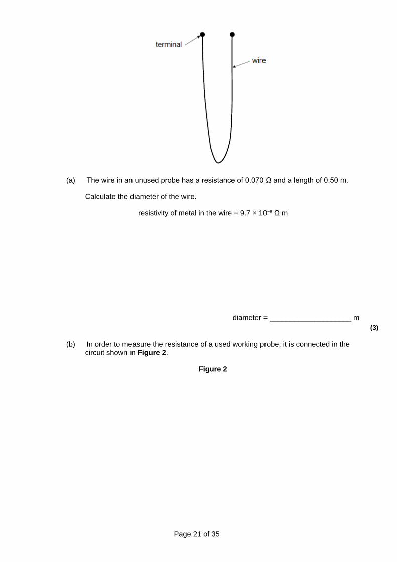
Q17. A wire probe is used to measure the rate of corrosion in a pipe carrying a corrosive liquid. The probe is made from the same metal as the pipe. Figure 1 shows the probe. The rate of corrosion of the wire in the probe is the same as in the pipe.
Figure 1
Page 21 of 35
(a) The wire in an unused probe has a resistance of 0.070 Ω and a length of 0.50 m.
Calculate the diameter of the wire.
resistivity of metal in the wire = 9.7 × 10⁻⁸ Ω m
diameter = ____________________ m (3)
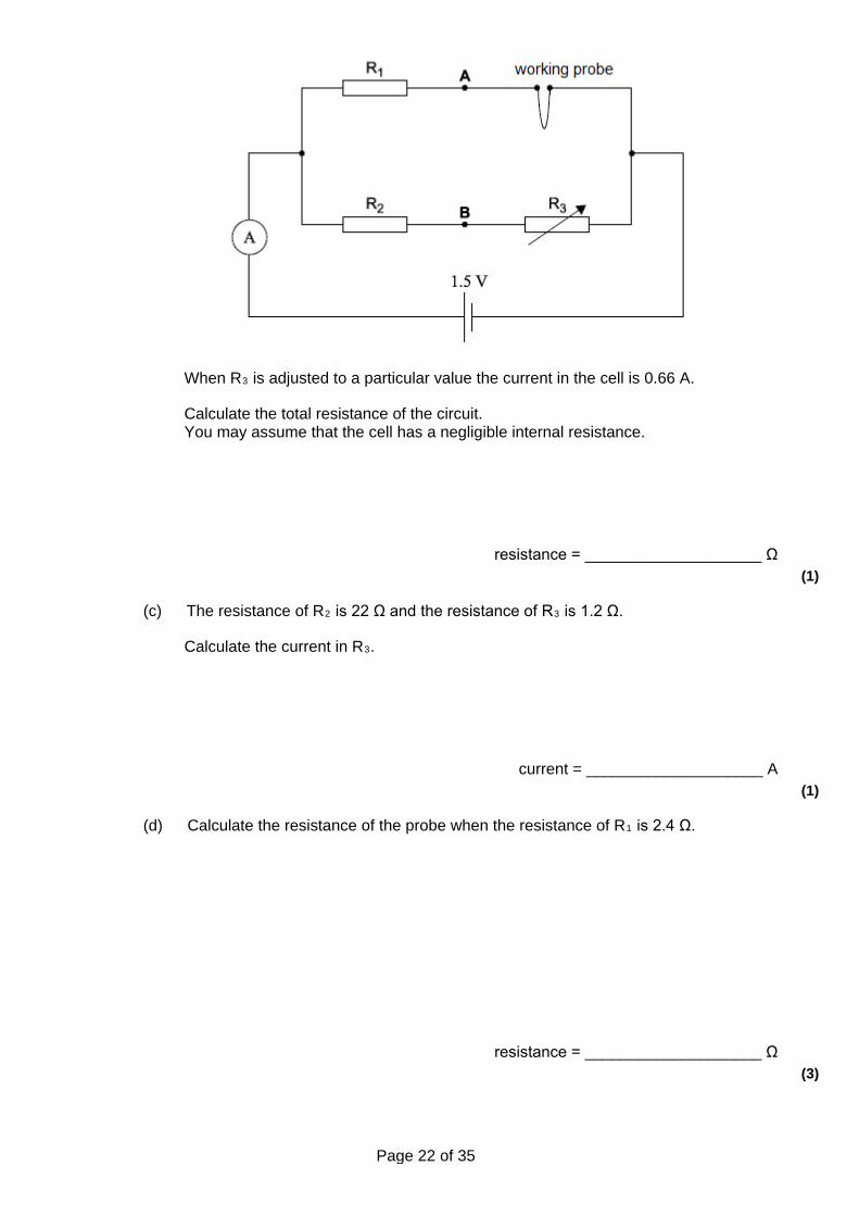
(b) In order to measure the resistance of a used working probe, it is connected in the circuit shown in Figure 2.
Figure 2
Page 22 of 35
When R3 is adjusted to a particular value the current in the cell is 0.66 A.
Calculate the total resistance of the circuit. You may assume that the cell has a negligible internal resistance.
resistance = ____________________ Ω (1)
(c) The resistance of R2 is 22 Ω and the resistance of R3 is 1.2 Ω.
Calculate the current in R3.
current = ____________________ A (1)
(d) Calculate the resistance of the probe when the resistance of R1 is 2.4 Ω.
resistance = ____________________ Ω (3)
Page 23 of 35
(e) Calculate the percentage change in the diameter of the probe when its resistance increases by 1.6 %.
percentage change = ____________________ % (2)
(f) A voltmeter is connected between points A and B in the circuit and R3 stays at 1.2 Ω.
Explain, without calculation, why the reading on the voltmeter does not change when the cell in the circuit is replaced with another cell of the same emf but a significant internal resistance.
___________________________________________________________________
___________________________________________________________________
___________________________________________________________________
___________________________________________________________________
___________________________________________________________________ (2)
(Total 12 marks)
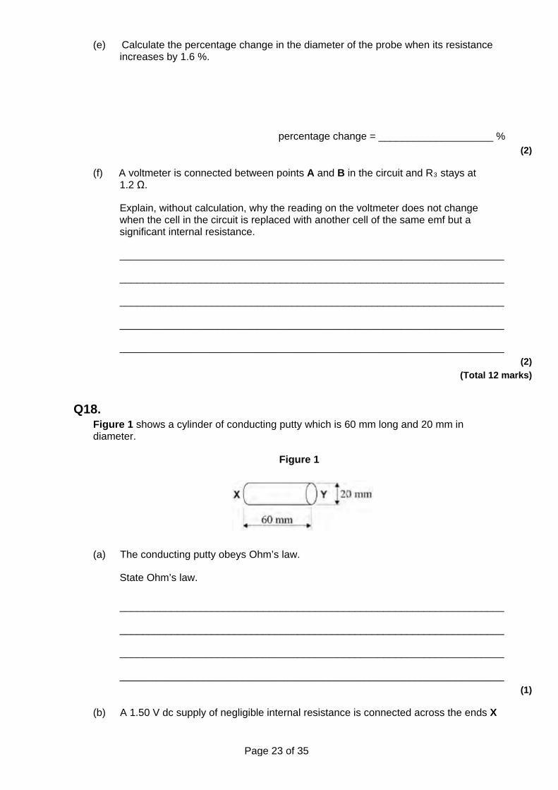
Q18. Figure 1 shows a cylinder of conducting putty which is 60 mm long and 20 mm in diameter.
Figure 1
(a) The conducting putty obeys Ohm’s law.
State Ohm’s law.
___________________________________________________________________
___________________________________________________________________
___________________________________________________________________
___________________________________________________________________ (1)
(b) A 1.50 V dc supply of negligible internal resistance is connected across the ends X
Page 24 of 35
and Y of the cylinder of putty. The resistance of the cylinder of putty is 20.0 Ω.
Calculate, in mA, the current in the putty.
current = _________________ mA (1)
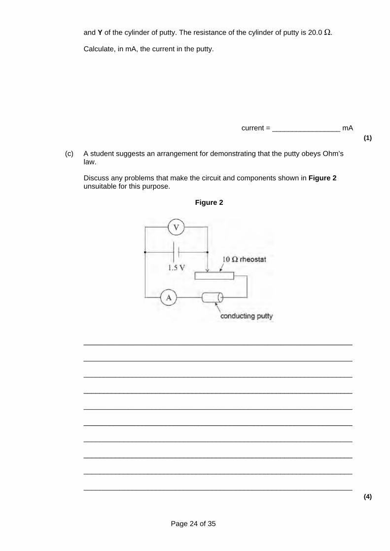
(c) A student suggests an arrangement for demonstrating that the putty obeys Ohm’s law.
Discuss any problems that make the circuit and components shown in Figure 2 unsuitable for this purpose.
Figure 2
___________________________________________________________________
___________________________________________________________________
___________________________________________________________________
___________________________________________________________________
___________________________________________________________________
___________________________________________________________________
___________________________________________________________________
___________________________________________________________________
___________________________________________________________________
___________________________________________________________________ (4)
Page 25 of 35
(d) Show that the resistivity ρ of the putty can be calculated using the formula
× volume of the cylinder
where R is the resistance of the cylinder and l is the length of the cylinder. (1)
(e) Calculate, using the formula in part (d), the resistivity of the putty. Give an appropriate unit for your answer.
resistivity = _______________ unit = ____________ (3)
(Total 10 marks)
Q19. A car battery has an emf of 12 V and an internal resistance of 9.5 × 10⁻³ Ω. When the battery is used to start a car the current through the battery is 420 A.
(a) Calculate the voltage across the terminals of the battery, when the current through the battery is 420 A.
___________________________________________________________________
___________________________________________________________________
___________________________________________________________________
___________________________________________________________________
answer ____________________ V (2)
(b) The copper cable connecting the starter motor to the battery has a length of 0.75 m and cross-sectional area of 7.9 × 10⁻⁵ m2. The resistance of the cable is 1.6 × 10⁻³ Ω.
Calculate the resistivity of the copper giving an appropriate unit.
___________________________________________________________________
___________________________________________________________________
___________________________________________________________________
___________________________________________________________________
___________________________________________________________________
Page 26 of 35
___________________________________________________________________
answer ____________________ (3)
(Total 5 marks)
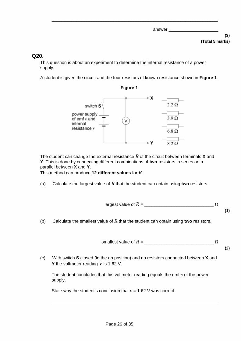
Q20. This question is about an experiment to determine the internal resistance of a power supply.
A student is given the circuit and the four resistors of known resistance shown in Figure 1.
Figure 1
The student can change the external resistance R of the circuit between terminals X and Y. This is done by connecting different combinations of two resistors in series or in parallel between X and Y. This method can produce 12 different values for R.
(a) Calculate the largest value of R that the student can obtain using two resistors.
largest value of R = ____________________________ Ω (1)
(b) Calculate the smallest value of R that the student can obtain using two resistors.
smallest value of R = ____________________________ Ω (2)
(c) With switch S closed (in the on position) and no resistors connected between X and Y the voltmeter reading V is 1.62 V.
The student concludes that this voltmeter reading equals the emf ε of the power supply.
State why the student’s conclusion that ε = 1.62 V was correct.
___________________________________________________________________
Page 27 of 35
___________________________________________________________________
___________________________________________________________________ (1)
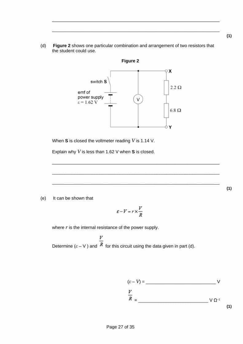
(d) Figure 2 shows one particular combination and arrangement of two resistors that the student could use.
Figure 2
When S is closed the voltmeter reading V is 1.14 V.
Explain why V is less than 1.62 V when S is closed.
___________________________________________________________________
___________________________________________________________________
___________________________________________________________________ (1)
(e) It can be shown that
where r is the internal resistance of the power supply.
Determine (ε – V ) and for this circuit using the data given in part (d).
(ε – V) = ____________________________ V
= ____________________________ V Ω–1
(1)
Page 28 of 35
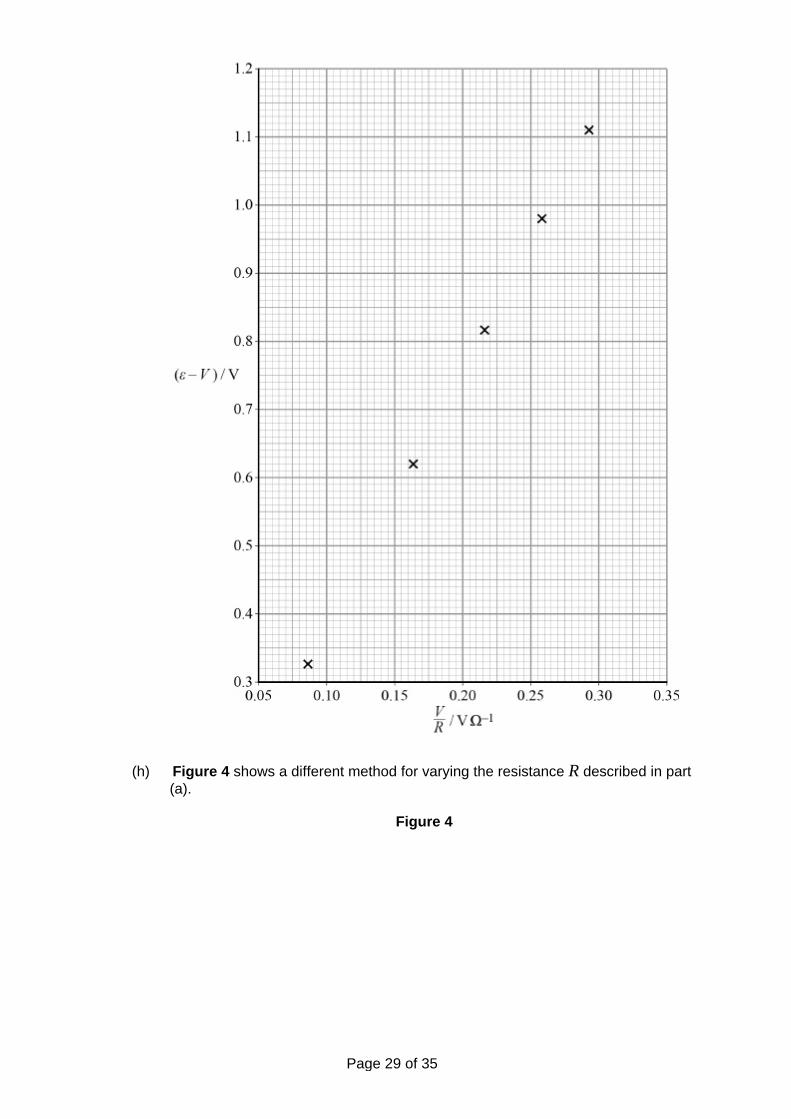
(f) The student obtains values of V for five further different values of R.
These data were used to produce the graph of (ε – V) against in Figure 3.
Plot the point you determined in part (e) on Figure 3 and add a suitable best-fit line. (1)
(g) Use Figure 3 to determine r.
r = ____________________________ Ω (2)
Figure 3
Page 29 of 35
(h) Figure 4 shows a different method for varying the resistance R described in part (a).
Figure 4
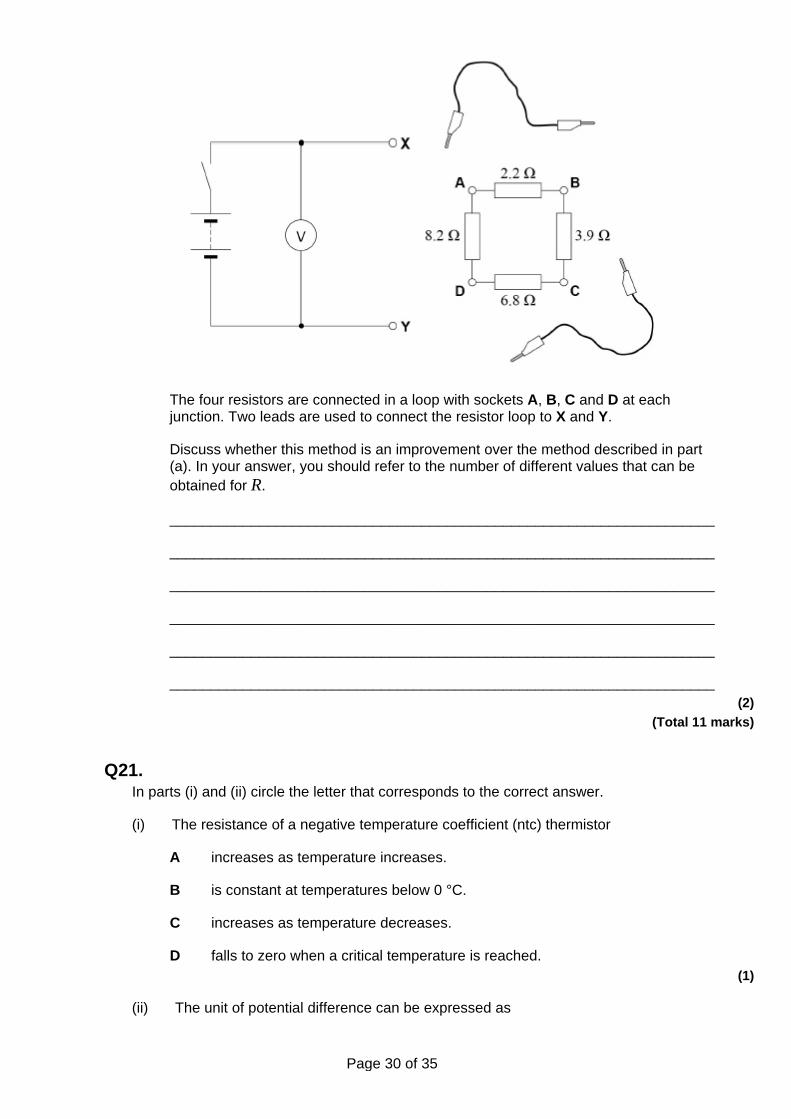
Page 30 of 35
The four resistors are connected in a loop with sockets A, B, C and D at each junction. Two leads are used to connect the resistor loop to X and Y.
Discuss whether this method is an improvement over the method described in part (a). In your answer, you should refer to the number of different values that can be obtained for R.
___________________________________________________________________
___________________________________________________________________
___________________________________________________________________
___________________________________________________________________
___________________________________________________________________
___________________________________________________________________ (2)
(Total 11 marks)
Q21. In parts (i) and (ii) circle the letter that corresponds to the correct answer.
(i) The resistance of a negative temperature coefficient (ntc) thermistor
A increases as temperature increases.
B is constant at temperatures below 0 °C.
C increases as temperature decreases.
D falls to zero when a critical temperature is reached. (1)
(ii) The unit of potential difference can be expressed as
Page 31 of 35
A C s–1
B J C–1
C V A–1
D J A–1
(1) (Total 2 marks)
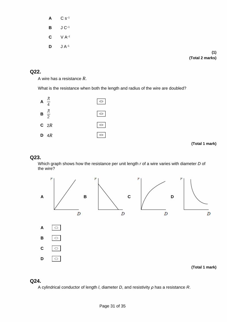
Q22. A wire has a resistance R.
What is the resistance when both the length and radius of the wire are doubled?
A
B
C 2R
D 4R (Total 1 mark)
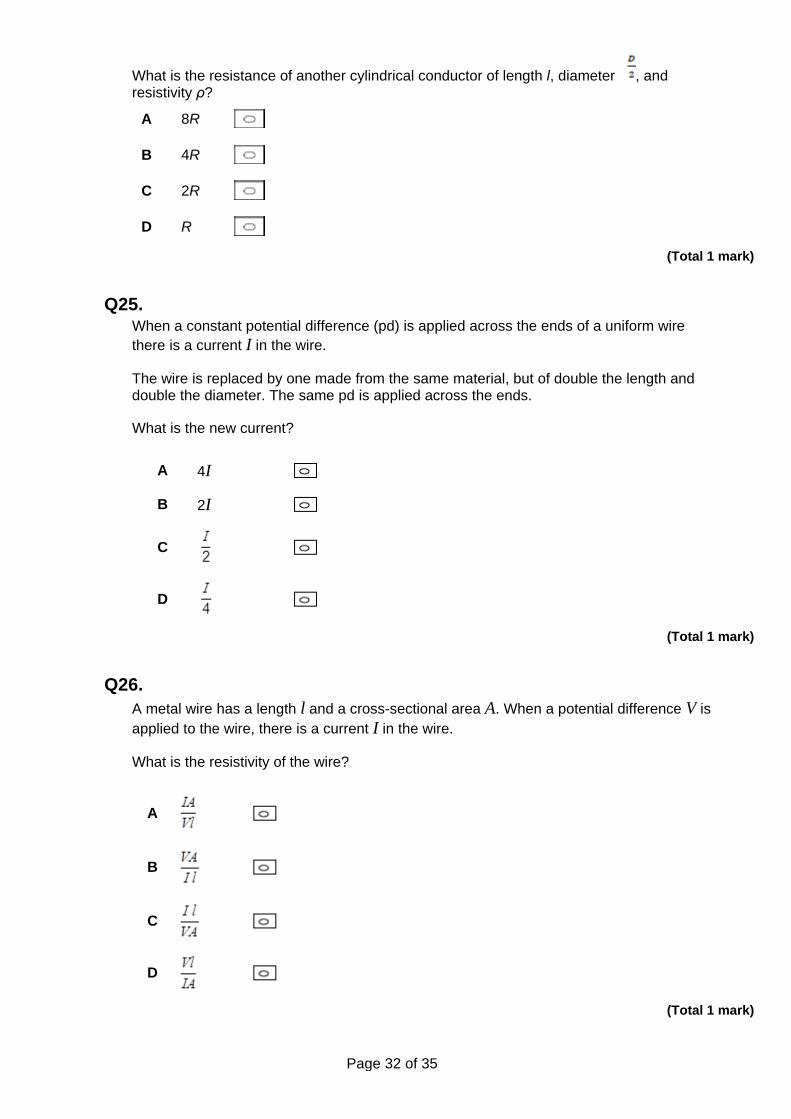
Q23. Which graph shows how the resistance per unit length r of a wire varies with diameter D of the wire?
A
B
C
D
A
B
C
D (Total 1 mark)
Q24. A cylindrical conductor of length l, diameter D, and resistivity ρ has a resistance R.
Page 32 of 35
What is the resistance of another cylindrical conductor of length l, diameter , and resistivity ρ?
A 8R
B 4R
C 2R
D R
(Total 1 mark)
Q25. When a constant potential difference (pd) is applied across the ends of a uniform wire there is a current I in the wire.
The wire is replaced by one made from the same material, but of double the length and double the diameter. The same pd is applied across the ends.
What is the new current?
A 4I B 2I
C
D
(Total 1 mark)
Q26. A metal wire has a length l and a cross-sectional area A. When a potential difference V is applied to the wire, there is a current I in the wire.
What is the resistivity of the wire?
A
B
C
D
(Total 1 mark)
Page 33 of 35
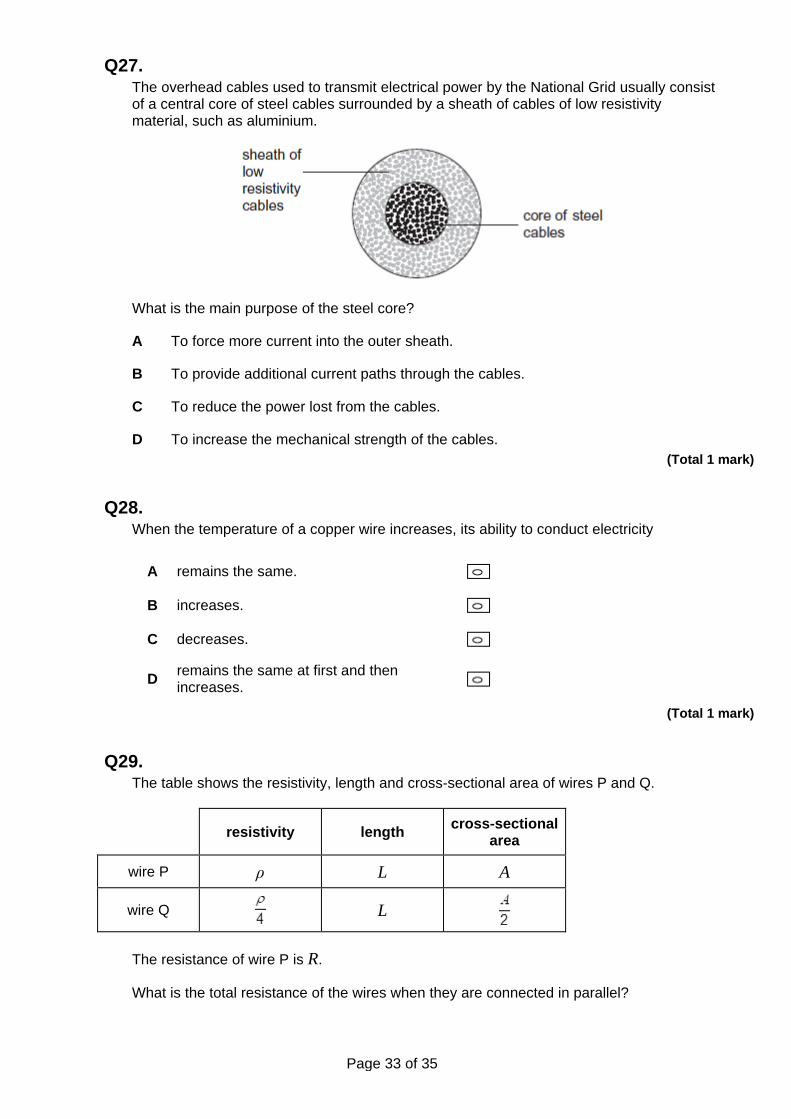
Q27. The overhead cables used to transmit electrical power by the National Grid usually consist of a central core of steel cables surrounded by a sheath of cables of low resistivity material, such as aluminium.
What is the main purpose of the steel core?
A To force more current into the outer sheath.
B To provide additional current paths through the cables.
C To reduce the power lost from the cables.
D To increase the mechanical strength of the cables. (Total 1 mark)
Q28. When the temperature of a copper wire increases, its ability to conduct electricity
A remains the same.
B increases.
C decreases.
D remains the same at first and then increases.
(Total 1 mark)
Q29. The table shows the resistivity, length and cross-sectional area of wires P and Q.
resistivity length cross-sectional area
wire P ρ L A
wire Q L
The resistance of wire P is R.
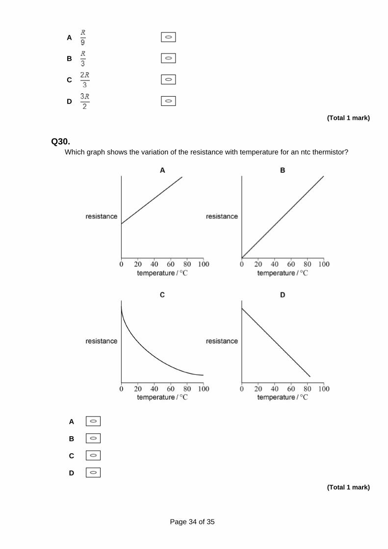
What is the total resistance of the wires when they are connected in parallel?
Page 34 of 35
A
B
C
D
(Total 1 mark)
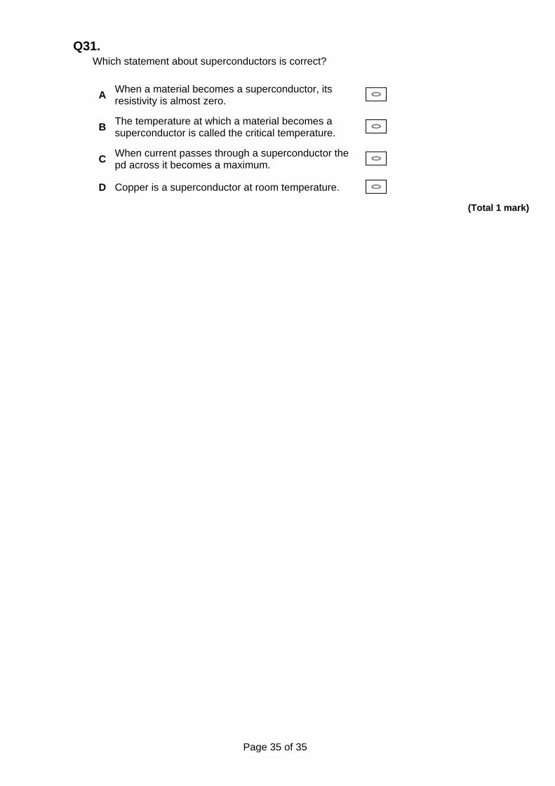
Q30. Which graph shows the variation of the resistance with temperature for an ntc thermistor?
A
B
C
D (Total 1 mark)
Page 35 of 35
Q31. Which statement about superconductors is correct?
A When a material becomes a superconductor, its resistivity is almost zero.
B The temperature at which a material becomes a superconductor is called the critical temperature.
C When current passes through a superconductor the pd across it becomes a maximum.
D Copper is a superconductor at room temperature. (Total 1 mark)


![Topic 5 Electricity 31.1.2018 [140 marks] · Topic 5 Electricity 31.1.2018 [140 marks] 1. The graph shows the variation of current with potential difference for a filament lamp. [1](https://static.fdocument.org/doc/165x107/5e625a0348969177d31d39ab/topic-5-electricity-3112018-140-marks-topic-5-electricity-3112018-140-marks.jpg)