5.2 Electricity - Current-Voltage characteristics - Qs · Page 1 of 36 5.2 Electricity -...
36
Page 1 of 36 5.2 Electricity - Current-Voltage characteristics – Questions Q1. The graph shows the current–voltage (I–V) characteristics of a filament lamp. V / V What is the resistance of the filament when the potential difference (pd) across it is 4.0 V? A 500 Ω B 1700 Ω C 2000 Ω D 6000 Ω (Total 1 mark) Q2. A student wishes to collect data so he can plot the I-V curve for a semiconductor diode. (a) (i) Draw a suitable diagram of the circuit that would enable the student to collect this data. (3) (ii) Describe the procedure the student would follow in order to obtain an I-V curve for the semiconductor diode.
Transcript of 5.2 Electricity - Current-Voltage characteristics - Qs · Page 1 of 36 5.2 Electricity -...

Page 1 of 36
5.2 Electricity - Current-Voltage characteristics – Questions
Q1. The graph shows the current–voltage (I–V) characteristics of a filament lamp.
V / V
What is the resistance of the filament when the potential difference (pd) across it is 4.0 V?
A 500 Ω
B 1700 Ω
C 2000 Ω
D 6000 Ω (Total 1 mark)
Q2. A student wishes to collect data so he can plot the I-V curve for a semiconductor diode.
(a) (i) Draw a suitable diagram of the circuit that would enable the student to collect this data.
(3)
(ii) Describe the procedure the student would follow in order to obtain an I-V curve for the semiconductor diode.
Page 2 of 36
The quality of your written communication will be assessed in this question.
______________________________________________________________
______________________________________________________________
______________________________________________________________
______________________________________________________________
______________________________________________________________
______________________________________________________________
______________________________________________________________
______________________________________________________________
______________________________________________________________
______________________________________________________________
______________________________________________________________ (6)
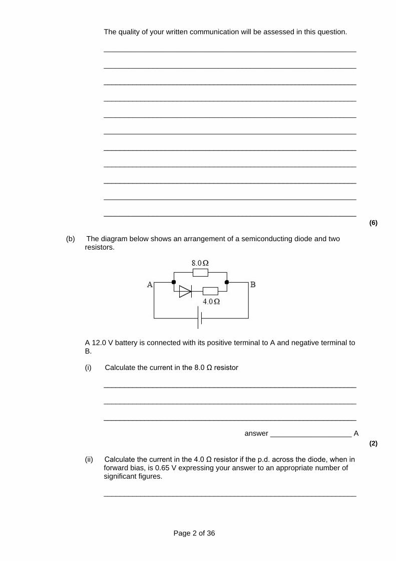
(b) The diagram below shows an arrangement of a semiconducting diode and two resistors.
A 12.0 V battery is connected with its positive terminal to A and negative terminal to B.
(i) Calculate the current in the 8.0 Ω resistor
______________________________________________________________
______________________________________________________________
______________________________________________________________
answer ____________________ A (2)
(ii) Calculate the current in the 4.0 Ω resistor if the p.d. across the diode, when in forward bias, is 0.65 V expressing your answer to an appropriate number of significant figures.
______________________________________________________________
Page 3 of 36
______________________________________________________________
______________________________________________________________
______________________________________________________________
answer ____________________ A (3)
(Total 14 marks)
Q3. (a) Some electrical components may be described as non-ohmic.
(i) Name an example, other than a diode, of a non-ohmic electrical component.
______________________________________________________________
(ii) State how the current-voltage characteristic of your chosen component shows that it is non-ohmic.
______________________________________________________________
______________________________________________________________
______________________________________________________________ (2)
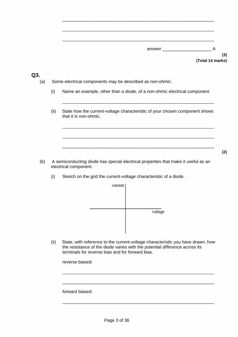
(b) A semiconducting diode has special electrical properties that make it useful as an electrical component.
(i) Sketch on the grid the current-voltage characteristic of a diode.
(ii) State, with reference to the current-voltage characteristic you have drawn, how the resistance of the diode varies with the potential difference across its terminals for reverse bias and for forward bias.
reverse biased:
______________________________________________________________
______________________________________________________________
forward biased:
______________________________________________________________
Page 4 of 36
______________________________________________________________ (4)
(Total 6 marks)
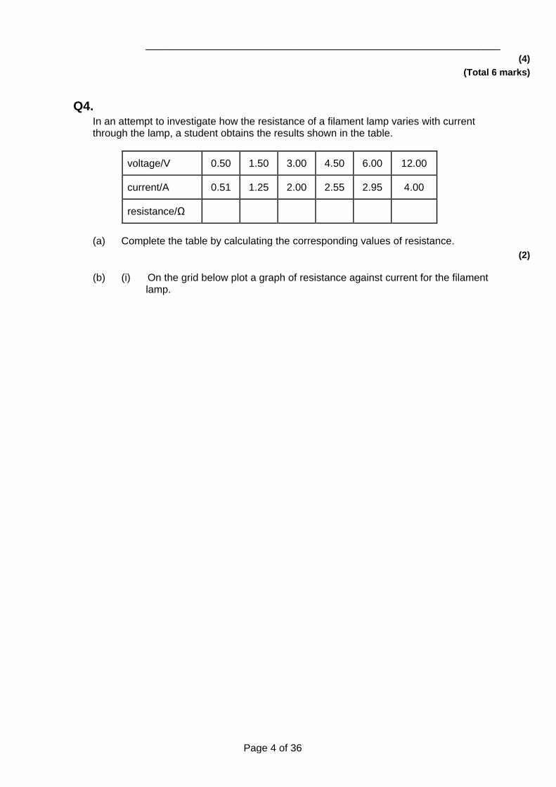
Q4. In an attempt to investigate how the resistance of a filament lamp varies with current through the lamp, a student obtains the results shown in the table.
voltage/V 0.50 1.50 3.00 4.50 6.00 12.00
current/A 0.51 1.25 2.00 2.55 2.95 4.00
resistance/Ω
(a) Complete the table by calculating the corresponding values of resistance. (2)
(b) (i) On the grid below plot a graph of resistance against current for the filament lamp.
Page 5 of 36
(ii) Use your graph to estimate the resistance of the filament lamp when no current flows through the lamp.
______________________________________________________________
(iii) Use your graph to determine the change in the resistance of the filament when the current increases
Page 6 of 36
from 0 to 1.0 A, _________________________________________________
______________________________________________________________
from 1.0 A to 2.0 A ______________________________________________
______________________________________________________________
(iv) Calculate the power dissipated in the lamp filament when the current through the filament is 1.0 A and 2.0 A.
1. ____________________________________________________________
______________________________________________________________
2. ____________________________________________________________
______________________________________________________________ (8)
(c) Using information from part (b)(iv), explain why the change in resistance of the filament is less for a current change of 0 to 1.0 A than for a current change of 1.0 A to 2.0 A. Do not attempt any calculation.
___________________________________________________________________
___________________________________________________________________
___________________________________________________________________ (2)
(Total 12 marks)
Q5. A filament lamp rated 12 V, 1.0 A has a resistance of 4.0 Ω when it carries no current.
(a) On the axes below, sketch the form of the current against voltage characteristic for this lamp.
(4)
Page 7 of 36
(b) The filament lamp is one example of a non-ohmic device.
(i) State what is meant by the term non-ohmic.
______________________________________________________________
______________________________________________________________
(ii) Name one other example of a non-ohmic device.
______________________________________________________________ (2)
(Total 6 marks)
Q6. (a) Draw, on the axes below, the current/voltage characteristic for a filament lamp.
Do not insert any values for current or voltage.
(3)
(b) Explain why the characteristic has the shape you have drawn.
___________________________________________________________________
___________________________________________________________________
___________________________________________________________________
___________________________________________________________________
___________________________________________________________________ (3)
(c) The current/voltage characteristic of a filament lamp is to be determined using a datalogger, the data then being fed into a computer to give a visual display of the characteristic. Draw the circuit diagram required for such an experiment and state what is varied so as to produce a range of values.
Page 8 of 36
___________________________________________________________________
___________________________________________________________________
___________________________________________________________________
___________________________________________________________________ (5)
(Total 11 marks)
Q7. (a) Using the axes below, sketch the characteristic of a silicon semiconductor diode for
forward bias and reverse bias.
Indicate approximate values on the voltage axis.
(4)
(b) Describe, with reference to the characteristic you have drawn, how the resistance of the diode changes with the voltage across the diode.
___________________________________________________________________
___________________________________________________________________
___________________________________________________________________
___________________________________________________________________ (3)
(Total 7 marks)
Q8. Columns A and B show some of the results from an experiment in which the current I through a component X was measured for various values of the potential difference V applied across it.
column A column B column C column D
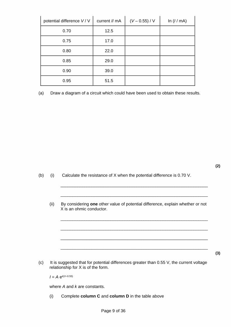
Page 9 of 36
potential difference V / V current I/ mA (V – 0.55) / V In (I / mA)
0.70 12.5
0.75 17.0
0.80 22.0
0.85 29.0
0.90 39.0
0.95 51.5
(a) Draw a diagram of a circuit which could have been used to obtain these results.
(2)
(b) (i) Calculate the resistance of X when the potential difference is 0.70 V.
______________________________________________________________
______________________________________________________________
(ii) By considering one other value of potential difference, explain whether or not X is an ohmic conductor.
______________________________________________________________
______________________________________________________________
______________________________________________________________
______________________________________________________________ (3)
(c) It is suggested that for potential differences greater than 0.55 V, the current voltage relationship for X is of the form.
I = A ek(V–0.55)
where A and k are constants.
(i) Complete column C and column D in the table above
Page 10 of 36
(ii) Plot a graph of 1n (I /mA ) on the y-axis against (V – 0.55) on the x-axis.
(Allow one sheet of graph paper)
(iii) Use your graph to determine the constants k and A.
______________________________________________________________
______________________________________________________________
______________________________________________________________
______________________________________________________________
______________________________________________________________
______________________________________________________________
______________________________________________________________
______________________________________________________________
______________________________________________________________
______________________________________________________________
(iv) On the basis of your graph, discuss the validity of the above relationship.
______________________________________________________________
______________________________________________________________
______________________________________________________________
______________________________________________________________ (10)
(Total 15 marks)
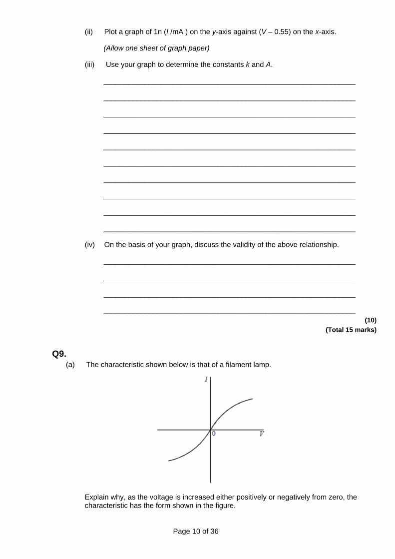
Q9. (a) The characteristic shown below is that of a filament lamp.
Explain why, as the voltage is increased either positively or negatively from zero, the characteristic has the form shown in the figure.
Page 11 of 36
___________________________________________________________________
___________________________________________________________________
___________________________________________________________________
___________________________________________________________________
___________________________________________________________________
___________________________________________________________________
___________________________________________________________________
___________________________________________________________________ (5)
(b) At a certain point on the characteristic, the power developed in the lamp is 20 W and the current is 90 mA. Calculate the resistance of the filament at this point on the characteristic.
___________________________________________________________________
___________________________________________________________________
___________________________________________________________________
___________________________________________________________________ (2)
(Total 7 marks)
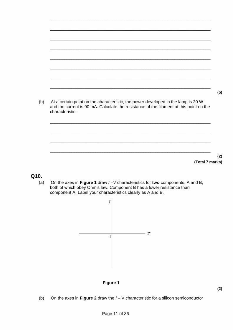
Q10. (a) On the axes in Figure 1 draw I –V characteristics for two components, A and B,
both of which obey Ohm’s law. Component B has a lower resistance than component A. Label your characteristics clearly as A and B.
Figure 1 (2)
(b) On the axes in Figure 2 draw the I – V characteristic for a silicon semiconductor
Page 12 of 36
diode, giving any relevant voltage values.
Figure 2 (3)
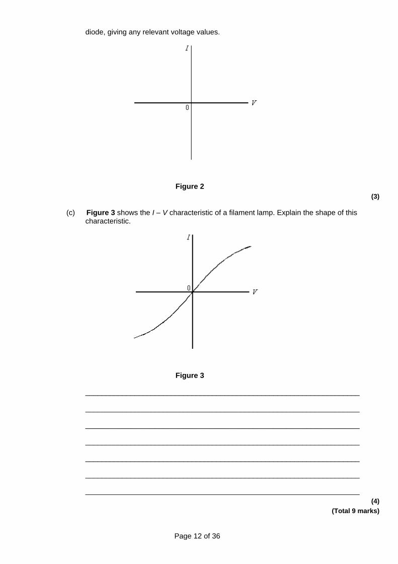
(c) Figure 3 shows the I – V characteristic of a filament lamp. Explain the shape of this characteristic.
Figure 3
___________________________________________________________________
___________________________________________________________________
___________________________________________________________________
___________________________________________________________________
___________________________________________________________________
___________________________________________________________________
___________________________________________________________________ (4)
(Total 9 marks)
Page 13 of 36
Q11. (a) A semiconducting diode is an example of a non-ohmic component. State what is
meant by a non-ohmic component.
___________________________________________________________________
___________________________________________________________________ (1)
(b) A filament lamp is also an example of a non-ohmic component.
(i) Sketch on the axes below the current-voltage characteristic for a filament lamp.
(2)
(ii) State, with reference to the current-voltage characteristic you have drawn, how the resistance of the lamp changes as the pd across its terminals changes.
______________________________________________________________
______________________________________________________________ (1)
(c) A filament lamp has a power rating of 36 W when there is a pd across its terminals of 12V.
(i) Calculate the resistance of the filament when the pd across its terminals is 12V.
answer = ______________________ Ω (2)
(ii) A student predicts that if the pd across the bulb is reduced to 6.0 V the power
Page 14 of 36
rating of the bulb would be 9.0 W. State and explain how in practice the power rating will be slightly different from this value.
______________________________________________________________
______________________________________________________________
______________________________________________________________
______________________________________________________________
______________________________________________________________
______________________________________________________________ (3)
(Total 9 marks)
Q12. (a) Define resistance.
___________________________________________________________________
___________________________________________________________________
___________________________________________________________________ (1)
(b) (i) Sketch onto the axes below a graph of the variation of current with potential difference for a filament lamp.
(1)
(ii) State and explain, in terms of electron flow, how the resistance of the filament lamp changes as the current in the lamp increases.
______________________________________________________________
______________________________________________________________
______________________________________________________________
Page 15 of 36
______________________________________________________________
______________________________________________________________
______________________________________________________________ (3)
(Total 5 marks)
Q13. (a) Sketch, on Figure 1, the current−voltage (IV) characteristic for a filament lamp for
currents up to its working power.
Figure 1
(2)
(b) (i) State what happens to the resistance of the filament lamp as the current increases.
______________________________________________________________ (1)
(ii) State and explain whether a filament lamp is an ohmic or non−ohmic conductor up to its working power.
______________________________________________________________
______________________________________________________________ (1)
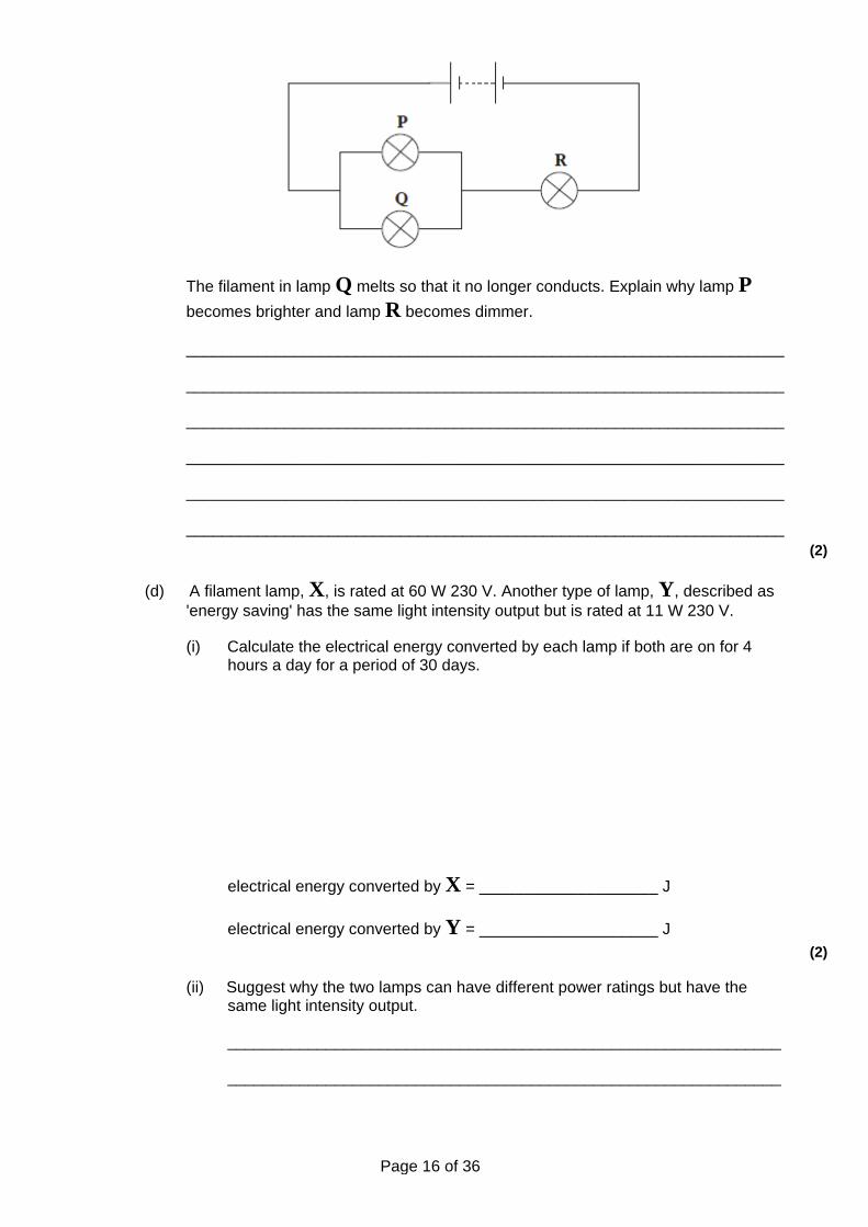
(c) Three identical filament lamps, P, Q and R are connected in the circuit shown in Figure 2.
Figure 2.
Page 16 of 36
The filament in lamp Q melts so that it no longer conducts. Explain why lamp P becomes brighter and lamp R becomes dimmer.
___________________________________________________________________
___________________________________________________________________
___________________________________________________________________
___________________________________________________________________
___________________________________________________________________
___________________________________________________________________ (2)
(d) A filament lamp, X, is rated at 60 W 230 V. Another type of lamp, Y, described as 'energy saving' has the same light intensity output but is rated at 11 W 230 V.
(i) Calculate the electrical energy converted by each lamp if both are on for 4 hours a day for a period of 30 days.
electrical energy converted by X = ____________________ J
electrical energy converted by Y = ____________________ J (2)
(ii) Suggest why the two lamps can have different power ratings but have the same light intensity output.
______________________________________________________________
______________________________________________________________
Page 17 of 36
______________________________________________________________
______________________________________________________________
______________________________________________________________ (2)
(Total 10 marks)
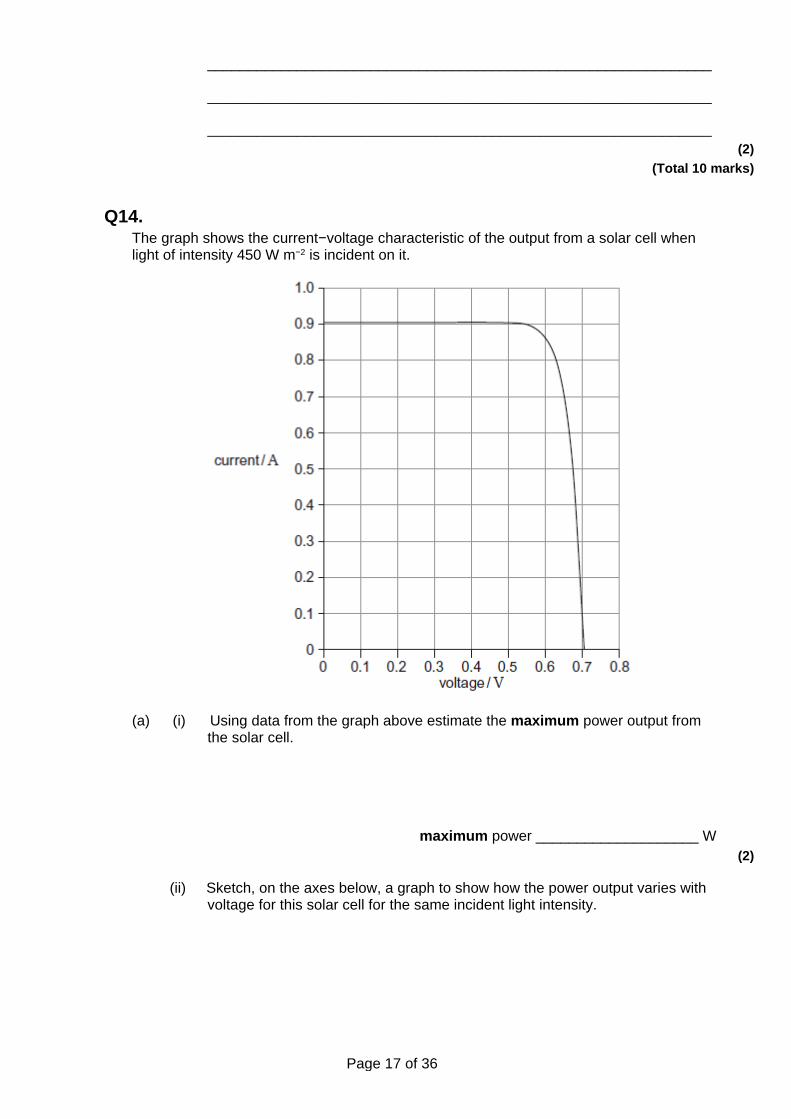
Q14. The graph shows the current−voltage characteristic of the output from a solar cell when light of intensity 450 W m−2 is incident on it.
(a) (i) Using data from the graph above estimate the maximum power output from the solar cell.
maximum power ____________________ W (2)
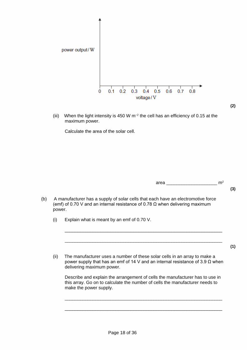
(ii) Sketch, on the axes below, a graph to show how the power output varies with voltage for this solar cell for the same incident light intensity.
Page 18 of 36
(2)
(iii) When the light intensity is 450 W m−2 the cell has an efficiency of 0.15 at the maximum power.
Calculate the area of the solar cell.
area ____________________ m2
(3)
(b) A manufacturer has a supply of solar cells that each have an electromotive force (emf) of 0.70 V and an internal resistance of 0.78 Ω when delivering maximum power.
(i) Explain what is meant by an emf of 0.70 V.
______________________________________________________________
______________________________________________________________ (1)
(ii) The manufacturer uses a number of these solar cells in an array to make a power supply that has an emf of 14 V and an internal resistance of 3.9 Ω when delivering maximum power.
Describe and explain the arrangement of cells the manufacturer has to use in this array. Go on to calculate the number of cells the manufacturer needs to make the power supply.
______________________________________________________________
______________________________________________________________
Page 19 of 36
______________________________________________________________
______________________________________________________________
______________________________________________________________
number of cells ____________________ (4)
(c) Communications satellites use solar cells to generate electrical power. Discuss why solar cells are appropriate for this task.
Your answer should refer to: • any additional features that would be needed to ensure that the satellite’s
electrical systems operate continuously • whether solar cell arrays are appropriate for space probes that travel to the
edge of the solar system.
The quality of your written communication will be assessed in your answer. (6)
(Total 18 marks)
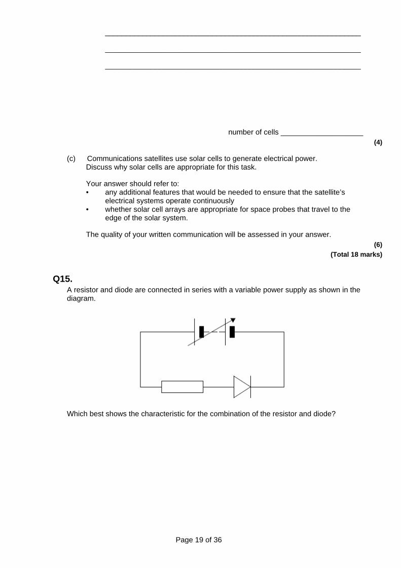
Q15. A resistor and diode are connected in series with a variable power supply as shown in the diagram.
Which best shows the characteristic for the combination of the resistor and diode?
Page 20 of 36
A
B
C
D (Total 1 mark)
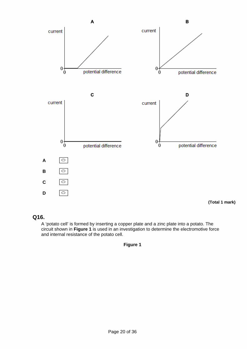
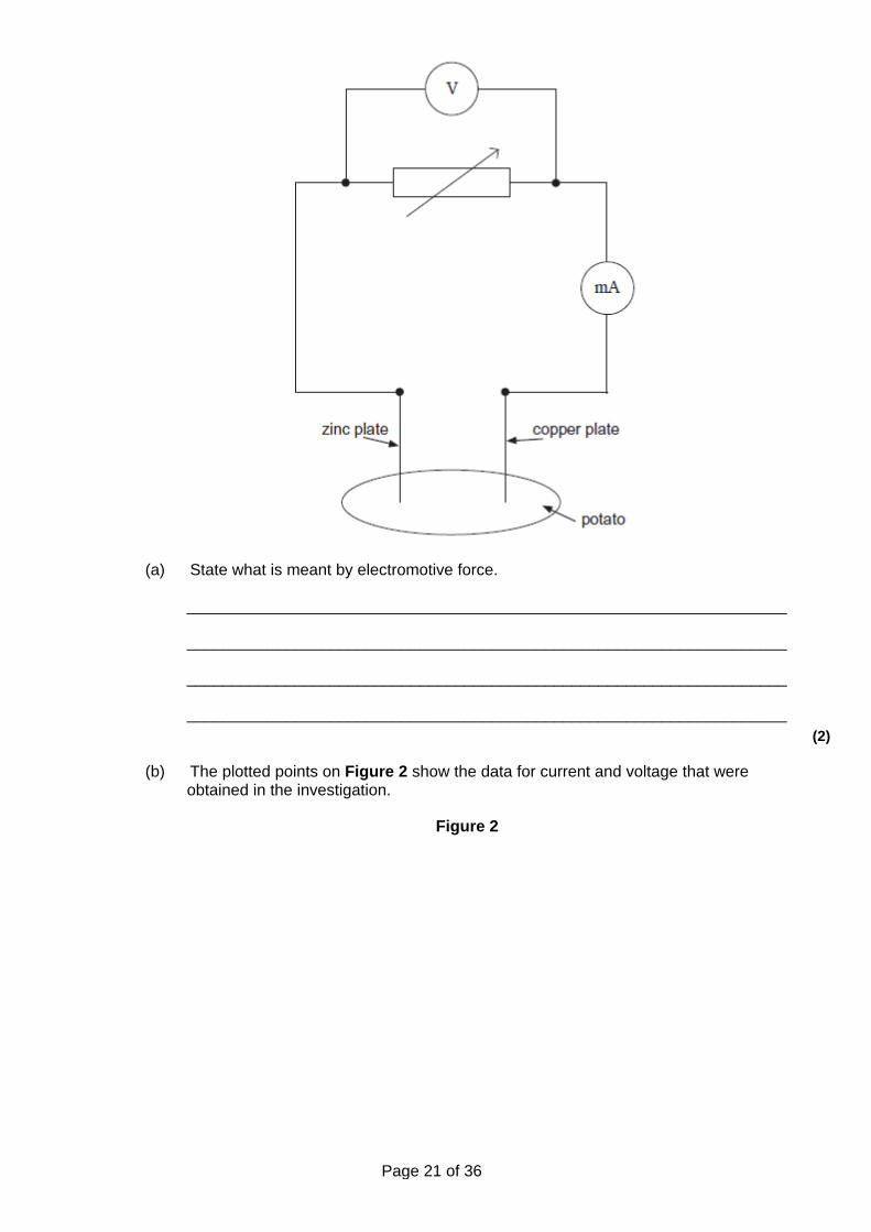
Q16. A ‘potato cell’ is formed by inserting a copper plate and a zinc plate into a potato. The circuit shown in Figure 1 is used in an investigation to determine the electromotive force and internal resistance of the potato cell.
Figure 1
Page 21 of 36
(a) State what is meant by electromotive force.
___________________________________________________________________
___________________________________________________________________
___________________________________________________________________
___________________________________________________________________ (2)
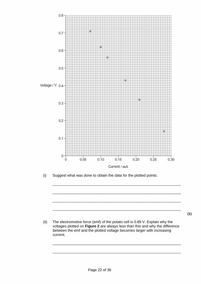
(b) The plotted points on Figure 2 show the data for current and voltage that were obtained in the investigation.
Figure 2
Page 22 of 36
(i) Suggest what was done to obtain the data for the plotted points.
______________________________________________________________
______________________________________________________________
______________________________________________________________
______________________________________________________________ (1)
(ii) The electromotive force (emf) of the potato cell is 0.89 V. Explain why the voltages plotted on Figure 2 are always less than this and why the difference between the emf and the plotted voltage becomes larger with increasing current.
______________________________________________________________
______________________________________________________________
Page 23 of 36
______________________________________________________________
______________________________________________________________
______________________________________________________________
______________________________________________________________
______________________________________________________________ (3)
(iii) Use Figure 2 to determine the internal resistance of the potato cell.
internal resistance = ____________________ Ω (3)
(c) A student decides to use two potato cells in series as a power supply for a light emitting diode (LED). In order for the LED to work as required, it needs a voltage of at least 1.6 V and a current of 20 mA.
Explain whether the LED will work as required.
___________________________________________________________________
___________________________________________________________________
___________________________________________________________________
___________________________________________________________________
___________________________________________________________________
___________________________________________________________________ (2)
(Total 11 marks)
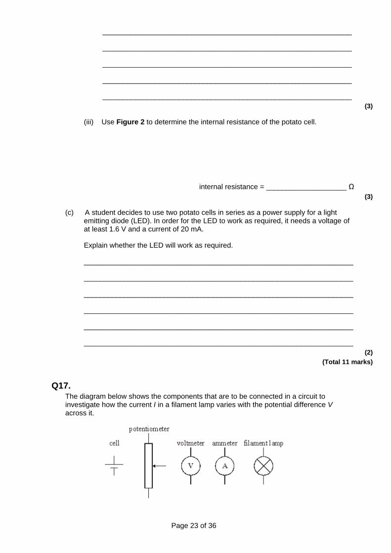
Q17. The diagram below shows the components that are to be connected in a circuit to investigate how the current I in a filament lamp varies with the potential difference V across it.
Page 24 of 36
(a) Draw below, a circuit diagram to show how these components should be connected to obtain voltage and current data over the full range from 0 V to the maximum voltage available from the cell.
(2)
(b) The lamp used is rated at 1.25 V, 0.3 W. Calculate the current in the lamp when it is working normally.
Current ____________________ (1)
(c) Sketch on the axes below the shape of the graph of I against V that the results of the experiment should produce.
(1)
(Total 4 marks)
Q18. (a) State Ohm’s law.
___________________________________________________________________
___________________________________________________________________
___________________________________________________________________ (2)
(b) A filament lamp labelled ‘12 V, 2.0 A’ has a constant resistance of 2.0 Ω for electrical currents up to 0.50 A.
Sketch on the axes below the current-voltage graph for this lamp over the range of voltages shown. Show clearly any calculations you made in order to answer the question.
Page 25 of 36
(3)
(c) Sketch on the axes below the current-voltage characteristic for a semi-conductor diode.
(3)
(Total 8 marks)
Q19. (a) The diagram below shows a graph of V against I for a filament lamp. Calculate the
maximum resistance of the lamp over the range shown by the graph.
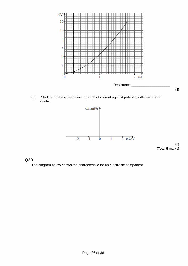
Page 26 of 36
Resistance ____________________ (3)
(b) Sketch, on the axes below, a graph of current against potential difference for a diode.
(2)
(Total 5 marks)
Q20. The diagram below shows the characteristic for an electronic component.
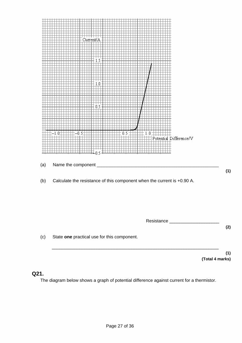
Page 27 of 36
(a) Name the component _________________________________________________ (1)
(b) Calculate the resistance of this component when the current is +0.90 A.
Resistance ____________________ (2)
(c) State one practical use for this component.
___________________________________________________________________ (1)
(Total 4 marks)
Q21. The diagram below shows a graph of potential difference against current for a thermistor.
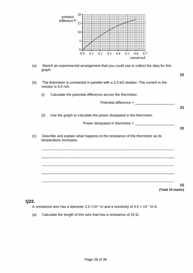
Page 28 of 36
(a) Sketch an experimental arrangement that you could use to collect the data for this graph.
(3)
(b) The thermistor is connected in parallel with a 2.0 kΩ resistor. The current in the resistor is 6.0 mA.
(i) Calculate the potential difference across the thermistor.
Potential difference = ____________________ (2)
(ii) Use the graph to calculate the power dissipated in the thermistor.
Power dissipated in thermistor = ____________________ (3)
(c) Describe and explain what happens to the resistance of the thermistor as its temperature increases.
___________________________________________________________________
___________________________________________________________________
___________________________________________________________________
___________________________________________________________________
___________________________________________________________________ (2)
(Total 10 marks)
Q22. A resistance wire has a diameter 2.0 ×10⁻⁴ m and a resistivity of 4.5 × 10⁻⁷ Ω m.
(a) Calculate the length of this wire that has a resistance of 25 Ω.
Page 29 of 36
length of wire ____________________ (3)
(b) The resistivity of the wire increases as the current increases. Sketch, on the axes below, the variation of current, I, with potential difference, V, across the wire for both positive and negative potential differences.
(2)
(Total 5 marks)
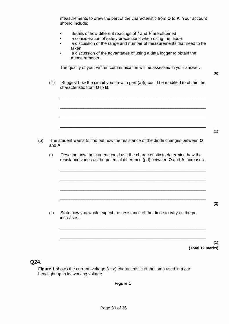
Q23. (a) The graph shows the current–voltage (I–V) characteristic curve for a semiconductor
diode.
In order to produce this characteristic a student is given suitable equipment including an ammeter and a voltmeter.
(i) Draw a labelled circuit diagram of the apparatus that the student could use to obtain the part of the characteristic from O to A.
(2)
(ii) Describe how the student could use the circuit in part (a)(i) to obtain sufficient
Page 30 of 36
measurements to draw the part of the characteristic from O to A. Your account should include:
• details of how different readings of I and V are obtained • a consideration of safety precautions when using the diode • a discussion of the range and number of measurements that need to be
taken • a discussion of the advantages of using a data logger to obtain the
measurements.
The quality of your written communication will be assessed in your answer. (6)
(iii) Suggest how the circuit you drew in part (a)(i) could be modified to obtain the characteristic from O to B.
______________________________________________________________
______________________________________________________________
______________________________________________________________
______________________________________________________________ (1)
(b) The student wants to find out how the resistance of the diode changes between O and A.
(i) Describe how the student could use the characteristic to determine how the resistance varies as the potential difference (pd) between O and A increases.
______________________________________________________________
______________________________________________________________
______________________________________________________________
______________________________________________________________ (2)
(ii) State how you would expect the resistance of the diode to vary as the pd increases.
______________________________________________________________
______________________________________________________________ (1)
(Total 12 marks)
Q24. Figure 1 shows the current–voltage (I−V) characteristic of the lamp used in a car headlight up to its working voltage.
Figure 1
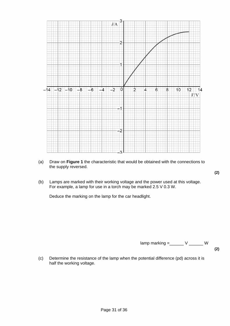
Page 31 of 36
(a) Draw on Figure 1 the characteristic that would be obtained with the connections to the supply reversed.
(2)
(b) Lamps are marked with their working voltage and the power used at this voltage. For example, a lamp for use in a torch may be marked 2.5 V 0.3 W.
Deduce the marking on the lamp for the car headlight.
lamp marking =______ V ______ W (2)
(c) Determine the resistance of the lamp when the potential difference (pd) across it is half the working voltage.
Page 32 of 36
resistance ___________________ Ω (1)
(d) Explain, without further calculation, how the resistance of the lamp varies as the voltage across it is increased from zero to its working voltage.
___________________________________________________________________
___________________________________________________________________
___________________________________________________________________
___________________________________________________________________
___________________________________________________________________
___________________________________________________________________
___________________________________________________________________ (3)
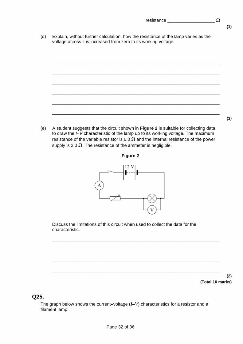
(e) A student suggests that the circuit shown in Figure 2 is suitable for collecting data to draw the I−V characteristic of the lamp up to its working voltage. The maximum resistance of the variable resistor is 6.0 Ω and the internal resistance of the power supply is 2.0 Ω. The resistance of the ammeter is negligible.
Figure 2
Discuss the limitations of this circuit when used to collect the data for the characteristic.
___________________________________________________________________
___________________________________________________________________
___________________________________________________________________
___________________________________________________________________ (2)
(Total 10 marks)
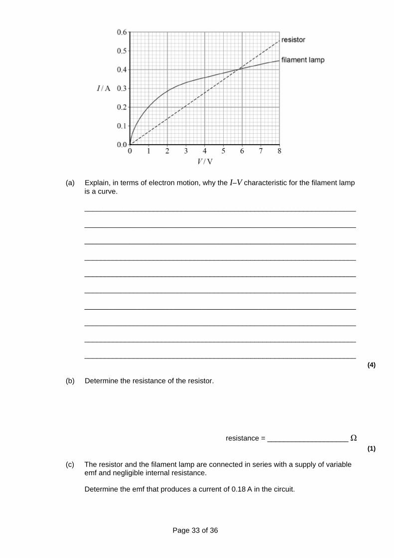
Q25. The graph below shows the current–voltage (I–V) characteristics for a resistor and a filament lamp.
Page 33 of 36
(a) Explain, in terms of electron motion, why the I–V characteristic for the filament lamp is a curve.
___________________________________________________________________
___________________________________________________________________
___________________________________________________________________
___________________________________________________________________
___________________________________________________________________
___________________________________________________________________
___________________________________________________________________
___________________________________________________________________
___________________________________________________________________
___________________________________________________________________ (4)
(b) Determine the resistance of the resistor.
resistance = ____________________ Ω (1)
(c) The resistor and the filament lamp are connected in series with a supply of variable emf and negligible internal resistance.
Determine the emf that produces a current of 0.18 A in the circuit.
Page 34 of 36
emf = ____________________ V (3)
(d) The resistor and filament lamp are now connected in parallel.
Determine the resistance of the parallel combination when the emf of the supply is adjusted to be 4.0 V.
resistance = ____________________ Ω (3)
(e) The resistance of the filament lamp at its working temperature is 14 Ω.
The filament has a length of 0.36 m and a diameter of 32 µm.
Calculate the resistivity of the metal that is used for the filament when the lamp is at its working temperature.
Give an appropriate unit for your answer.
resistivity = ____________________ unit ___________ (3)
(Total 14 marks)
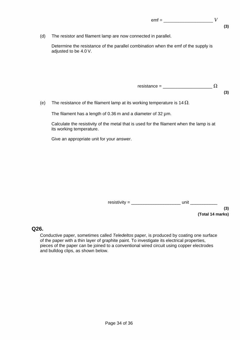
Q26. Conductive paper, sometimes called Teledeltos paper, is produced by coating one surface of the paper with a thin layer of graphite paint. To investigate its electrical properties, pieces of the paper can be joined to a conventional wired circuit using copper electrodes and bulldog clips, as shown below.
Page 35 of 36
It is known that the paper obeys Ohm’s Law providing the current through it does not exceed 200 mA. The company that manufactures it estimates that under typical laboratory conditions, the resistivity of the paint is between 1.0 × 10⁻⁵ Ωm and 5.0 × 10⁻⁵ Ωm.
Design an experiment that investigates some characteristic of the conductive paper.
You should consider the following in your answer.
• The variables you intend to measure and how to ensure that they are measured accurately.
• The factors you will need to control and how you will do this.
• The expected outcome of the experiment that you design.
• How any difficulties in performing the experiment could be overcome. (Total 8 marks)
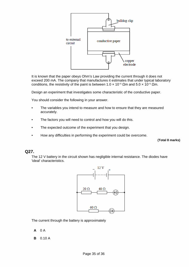
Q27. The 12 V battery in the circuit shown has negligible internal resistance. The diodes have 'ideal' characteristics.
The current through the battery is approximately
A 0 A
B 0.10 A
Page 36 of 36
C 0.20 A
D 0.40 A
(Total 1 mark)
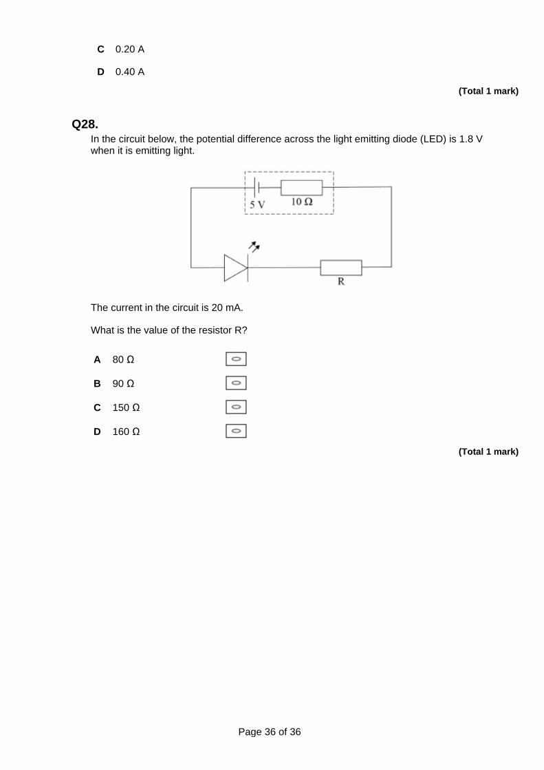
Q28. In the circuit below, the potential difference across the light emitting diode (LED) is 1.8 V when it is emitting light.
The current in the circuit is 20 mA.
What is the value of the resistor R?
A 80 Ω
B 90 Ω
C 150 Ω
D 160 Ω (Total 1 mark)