5060-UG-B-Composite 4/4/03 12:37 PM Page 2 · tor, it has intuitively labeled “electrical keys”...
68
USER’S GUIDE E LECTRI C AL C ® PRO MODEL 5060 ELECTRICALC ® PRO M–R/C CONSTRUCTION MASTER ® M+ AC +/– π DC Res Wire Res milli– EqGrnd D/R Size InsTrip SEFuse Starter Cond Type M–Type 125% PF% Eff% 90° 75° Ind/Sync 1Ø 3Ø Amb° Cu/Al 60° FrAir Prefs √ ___ x x 2 2 8 3 0 4 5 6 7 9 1 On/C Off Volts VA Amps Watts ParSz Length Rcl Stor WireSz DEFuse InvTime HPth kilo– VD% O-Load #XHHW #THW #THHN HPmotor CondSz % Grnd Set VD 60 Cu 125% WIRE SIZE 3O
Transcript of 5060-UG-B-Composite 4/4/03 12:37 PM Page 2 · tor, it has intuitively labeled “electrical keys”...
USER’SGUIDE
ELECTRICALC ® PROMODEL 5060
ELECTRICALC®
PRO
M–R/C
CONSTRUCTION MASTER®
M+
AC
+/–
π
DC Res
Wire Res
milli– EqGrnd D/R Size
InsTripSEFuseStarter
Cond Type
M–Type
125%
PF%
Eff%
90 °75° Ind/Sync
1Ø 3ØAmb°
Cu/Al 60°FrAir
Prefs
√___x
x2
2
8
3
0
4 5 6
7 9
1
On/COff
VoltsVA AmpsWatts
ParSz
Length
Rcl
Stor
WireSz
DEFuse InvTime
HPth kilo–
VD%
O-Load
#XHHW#THW #THHN
HPmotor
CondSz
%
Grnd
Set
VD60
Cu 125%WIRE SIZE3O
5060-UG-B-Composite 4/4/03 12:37 PM Page 1

5060-UG-B-Composite 4/4/03 12:37 PM Page 2
User ’s Guide — 1
Intr oducing the
ElectriCalc ® ProNow NEC®-Updateable!
The ElectriCalc® Pro is an invaluablecalculator for today’s busy electrical professional. Unlike a regular calcula-tor, it has intuitively labeled “electricalkeys” and conforms to the 2002 andfuture National Electrical Codes, allow-ing you to solve Code-related problemsquickly and accurately. The most com-mon NEC tables are now at your finger-tips!
An important new feature of the Elec-triCalc Pro is that it is now programmed to accept future NEC changes, allowingyou to conveniently install future Codeeditions in a few simple steps.
5060-UG-B-Composite 4/4/03 12:37 PM Page 3
2 — ElectriCalc Pro
The ElectriCalc Pro instantly solves forthe following:
♦ Volts, Amps, Volt-Amps, Watts, kVA, kW, PF%, EFF%, and DCResistance
♦ Copper or Aluminum Wire Sizes
♦ Parallel & Derated Wire Sizes
♦ Voltage Drop Wire Sizes, % andActual Voltage Drops, Voltage Drop Distances and Wire Resis-tances
♦ Grounding Conductors Sizes
♦ Motor Full-Load Amps
♦ Overload Protection Sizes
♦ NEMA Starter Sizes
♦ Conduit Sizes
♦ And much more!
5060-UG-B-Composite 4/4/03 12:37 PM Page 4
User ’s Guide — 3
Table of Contents
Installing NEC Updates . . . . . . . . . . . . . .4Key Definitions . . . . . . . . . . . . . . . . . . .5Preference Settings . . . . . . . . . . . . . . .26Default Settings . . . . . . . . . . . . . . . . .27Basic Math Operations . . . . . . . . . . . . .28Percent Calculations . . . . . . . . . . . . . .28Memory Functions . . . . . . . . . . . . . . . .29Kerchoff’s Law . . . . . . . . . . . . . . . . . .30Motor Horsepower . . . . . . . . . . . . . . . .34Ampacity Wire Sizing . . . . . . . . . . . . . .36Voltage Drop . . . . . . . . . . . . . . . . . . .42Ground Conductor Wire Size . . . . . . . . .48Equip. Grounding Conductor Wire Size . .49Fuse and Circuit Breaker Size . . . . . . . .50Starter Size . . . . . . . . . . . . . . . . . . . .51Overload Protection Size . . . . . . . . . . . .51Conduit Size . . . . . . . . . . . . . . . . . . . .52Error Codes . . . . . . . . . . . . . . . . . . . .57Battery Information . . . . . . . . . . . . . . .572002 NEC References . . . . . . . . . . . . . .58Updating Future Code Revisions . . . . . . .58Settings . . . . . . . . . . . . . . . . . . . . . . .59Warranty . . . . . . . . . . . . . . . . . . . . . .60Legal Notices . . . . . . . . . . . . . . . . . . .64
5060-UG-B-Composite 4/4/03 12:37 PM Page 5
4 — ElectriCalc Pro
Installing NEC Updates
Your ElectriCalc Pro is now updateablefor future National Electrical Code®
editions that are updated every three (3) years (next Code update is 2005). To upgrade your unit, follow the instruc-tions below:1) Purchase the NEC Update from CI
(see pricing & details from CI’s Website: www.calculated.com or call 1-800-854-8075). This Update is in theform of a chip that contains the newCode.
2) Once you receive the NEC Updatechip, you need to install it in yourElectriCalc Pro:
a)Turn calculator off.b)As a precaution, remove the bat-
tery (located back of calculator, topof unit) by sliding battery door outwith your thumbnail. Set aside.
c) Using a screwdriver, pop out thesquare tab located in the middlesection on the back of your calcu-lator.
d)Replace it with the new Update tabby inserting it into the slot.
e)Replace the battery door. f) Turn calculator on. Your calculator
is now updated and ready to use.
5060-UG-B-Composite 4/4/03 12:37 PM Page 6
User ’s Guide — 5
Key Definitions
Standar d Calculator Functions
[On/C] — On/ClearTurns on power. Pressing once clearsthe last entry and the display. Pressingtwice clears all non-permanent values.
[Off] — OffTurns all power off. Clears the memoryand most internal registers.
[+] [–] [x] [ ÷] [=]Arithmetic operation keys.
[0] – [9] & [•]Used for keying in numbers.
[%] — PercentFour function percent key.
[ ] Bac k Space FunctionUsed to delete entries one keystroke ata time (unlike the On/C function, whichdeletes the entire entry).
5060-UG-B-Composite 4/4/03 12:37 PM Page 7
6 — ElectriCalc Pro
[Set] — Second FunctionAccesses the secondary functionsshown above the keys when pressedprior to selection.
[Stor] — StoreUsed to store values when pressed justbefore a storage register (i.e., M+,AMPS, VOLTAGE, etc.).Displa ys: STOR.
[Rcl] — RecallRecalls a value stored in a register (e.g., to recall voltage drop % press [Rcl] [VD%]). Displa ys: RCL.
[Set] [ + ] — Pi ( π)Constant = 3.141593
[Set] [–] — Chang e Sign (+/–)Toggles the sign of the displayed value(from positive to negative or from nega-tive to positive).
[Set] [%] — x 2
Squares the displayed value.
[Set] [ ] — Square Root ( x )Square root function.
5060-UG-B-Composite 4/4/03 12:37 PM Page 8
User ’s Guide — 7
[Stor] [0] — Cum ulative Memor y Adds displayed value to Memory (e.g.,10 [M+], 20 [M+], [Rcl] [M+] = 30).Clears when the calculator is shut off.
[Rcl] [0] — Memor y RecallDisplays the value saved in (M+).
[Rcl] [Rc l] — Displa y/Clear Memor yDisplays and clears the value saved in(M+).
[Set] [Rc l] — Clear Memor yClears the value saved in (M+) withoutchanging displayed value.
Mode Set-up Functions
[Set] [x] — All-Clear (A C)Resets all settings and values to theirdefault settings.
[Set] [ ÷] — Pref erencesUse to set default settings or modes(see “Preference Settings” page 26)
[Set] [1] — Single-Phase (1Ø)Sets calculator to single-phase mode.Displa ys: 1Ø.
5060-UG-B-Composite 4/4/03 12:37 PM Page 9
8 — ElectriCalc Pro
[Set] [3] — Three-Phase (3Ø)Sets calculator to three-phase mode.Displa ys: 3Ø.
[Set] [2] — Ambient Temperature (Amb °)Permanently enters ambient tempera-ture for determining ampacity derivedwire sizes. Ambient temperature willonly change when entering a new value or by resetting the calculator ([Set] [x] ).Defaults to 30°C (86°F). Amb ° will display when the ambient temperature is other than 30°C (86°F). Displa ys:Amb °.
NOTE: The temperature units can bedisplayed in Celsius (°C) or Fahrenheit(°F) by using the preference function([Set][ ÷]).
[Set] [4] — Copper/Alumin umUsed to toggle between copper (de-fault) and aluminum wire types. Whenthe wire type is revised, any calculatedwire size will be re-calculated automati-cally. If a wire size is entered with thewrong wire type, pressing [Set] [4] willchange the material type without changing the size.Displa ys: Al or Cu.
5060-UG-B-Composite 4/4/03 12:37 PM Page 10
User ’s Guide — 9
[Set] [5] — Free Air (FrAir)Sets calculator into Free Air mode,which refers to NEC Table 310-17 forwire size calculations. Displa ys: FrAir .
[Set] [6] — 60 °C Wire Insulation Sets calculator to 60°C wire insulationtype for wire size calculations. This isthe default setting. Displa ys: 60.
[Set] [7] — 75 °C Wire Insulation Sets calculator to 75°C insulation typefor wire size calculations. Displa ys: 75.
[Set] [9] — 90 °C Wire Insulation Sets calculator to 90°C insulation typefor wire size calculations. Displa ys: 90.
Electrical Functions
[kilo-] — Kilo-This key is used with watts, amps, volts, and volt-amps to identify “kilo-”values.
[Set] [kilo-] — Milli-This key sequence is used with otherkeys watts, amps, volts, and volt-ampsto identify “milli-” values.
5060-UG-B-Composite 4/4/03 12:37 PM Page 11
10 — ElectriCalc Pro
[Amps] — AmpsEnters or calculates amps (using voltsand VA or watts). Displa ys: AMPS,KAMP or mAMP .
[Volts] — VoltsEnters or calculates volts (using amps,HPth, and VA or watts). Default value is240 volts. Displa ys: VOLT, KV, or mV.
[Set] [Volts] — DC ResistanceCalculates and displays DC resistance.Displa ys: OHMS.
[VA] — Volt-AmpsEnters or calculates volt-amps (usingamps, volts and horsepower or watts).Displa ys: VA, KVA, or mVA.
[Watts] — WattsEnters or calculates watts (using amps,volts, and VA or horsepower).Displa ys: WATT, KW, or mW.
[Set] [W atts] —P ower FactorEnters or calculates power factor per-centage (based on watts and VA). De-faults to 100%. Entered or calculatedpower factors greater than 100% willresult in an error. Displa ys: PF%.
5060-UG-B-Composite 4/4/03 12:37 PM Page 12
User ’s Guide — 1 1
[HPth] — Hor sepo wer (Theoretical)Enters or calculates theoretical horse-power (based on Amps, VA, watts, efficiency%, PF%, and/or volts). 1.0HPth correlates to 746 watts at 100%efficiency. Displa ys: HPth.
[Set] [HPth] — Efficienc yEnters or calculates the percent ratiobetween real power (watts) and theo-retical horsepower. Default: 100%.Entered or calculated efficienciesgreater than 100% will result in an er-ror. Displa ys: EFF%.
Motor Hor sepo wer Functions
The ElectriCalc Pro can be used todetermine motor full-load current (amps) based on entries for motorhorsepower (HP), phase and voltage.
You can also find an equivalent motorhorsepower if you have entered voltageand full load current values. Only HPand voltage entries as defined by NECTables 430-148 and 430-150 can beused to determine motor loads.
5060-UG-B-Composite 4/4/03 12:37 PM Page 13
12 — ElectriCalc Pro
[Set] [8] — Induction/ Sync hronous Motor ToggleToggles between induction and syn-chronous motor types. Displa ys: SYNC(synchronous) or IND (induction - de-fault).
[HPmotor] — Motor Hor sepo wer Enters or calculates motor horsepower.Displa ys: SYNC HP (synchronous) orHP IND (induction - default).
Ampacity Tables
The ElectriCalc Pro uses NEC Table310-16 (310-17 for Free Air) to find wiresizes and ampacity ratings of wires. The calculator uses the following data to calculate wire size: 1) insulation temperature rating (60°C, 75°C and90°C); 2) wire material (copper or alu-minum); and 3) ambient temperature.Only standard AWG wire sizes are used by the ElectriCalc Pro.
NOTE: 1/0, 2/0, 3/0 and 4/0 wires areentered using the [0] key (i.e., 0, 00, 000 and 0000).
[WireSz] — Wire Siz e/AmpacityEnters or calculates wire size based onampacity and voltage drop, if a voltagedrop length has been entered.
5060-UG-B-Composite 4/4/03 12:37 PM Page 14
User ’s Guide — 13
♦ First PressIf a wire length has been entered, thefirst press will show the larger of theampacity or voltage drop derived wiresize. The calculator will use the largervalue when calculations require a wiresize. If no voltage drop length has beenentered, the calculator will display thecalculated ampacity rated wire size.
♦ Second PressIf a wire length has been entered, thesecond press displays the smaller of the two wire sizes. If not solving for voltage drop wire size, then displays the maximum ampacity.
♦ Third PressIf a wire length has been entered, dis-plays the minimum wire ampacity rat-ing.
[Set] [WireSz] — 125% Ampacity Used for motor wire sizing when the wire must not exceed 80% of its ratedampacity (125%A). This keystroke calculates wire size based on 125% ofthe entered or calculated amps value.Displa ys: 125%.
5060-UG-B-Composite 4/4/03 12:37 PM Page 15

14 — ElectriCalc Pro
[ParSz] — Parallel Siz eUsed to find the size of parallel conduc-tors using amperage and an enteredquantity of wires. Parallel wire size computations smaller than 1/0 are dis-played as “none” (display shows “nonE ”) as the NEC does not allow parallel wire runs smaller than 1/0.
♦ First PressWhen preceded by a number, calcu-lates the applicable wire size for thatquantity of wires in parallel. Displa ys: PAR WIRE SIZE.
♦ Second PressDisplays the maximum adjusted am-pacity of the calculated parallel wiresize. Displa ys: WIRE A.
NOTE: No adjustments are made forderation.
[Set] [P arSz] — Derated Wire Siz eUsed to calculate derated wire sizes and allowable ampacity based on theentered quantity of wires, NEC Table310-16 and NEC Table 310-15(b)(2)(a).Derated wire sizes are not calculatedwhen there are less than 4 wires, orwhen the unit is in Free Air mode.
5060-UG-B-Composite 4/4/03 12:37 PM Page 16
User ’s Guide — 15
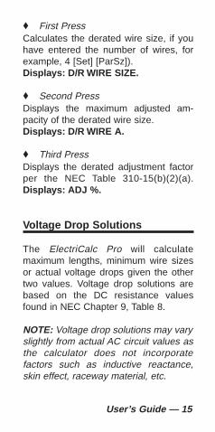
♦ First PressCalculates the derated wire size, if youhave entered the number of wires, forexample, 4 [Set] [ParSz]). Displa ys: D/R WIRE SIZE.
♦ Second PressDisplays the maximum adjusted am-pacity of the derated wire size. Displa ys: D/R WIRE A.
♦ Third PressDisplays the derated adjustment factorper the NEC Table 310-15(b)(2)(a).Displa ys: ADJ %.
Volta ge Drop Solutions
The ElectriCalc Pro will calculate maximum lengths, minimum wire sizesor actual voltage drops given the othertwo values. Voltage drop solutions arebased on the DC resistance valuesfound in NEC Chapter 9, Table 8.
NOTE: Voltage drop solutions may varyslightly from actual AC circuit values asthe calculator does not incorporate factors such as inductive reactance,skin effect, raceway material, etc.
5060-UG-B-Composite 4/4/03 12:37 PM Page 17
16 — ElectriCalc Pro
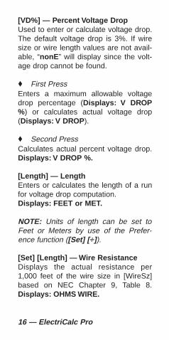
[VD%] — Percent Volta ge DropUsed to enter or calculate voltage drop.The default voltage drop is 3%. If wiresize or wire length values are not avail-able, “nonE ” will display since the volt-age drop cannot be found.
♦ First PressEnters a maximum allowable voltagedrop percentage (Displa ys: V DROP %) or calculates actual voltage drop(Displa ys: V DROP).
♦ Second PressCalculates actual percent voltage drop.Displa ys: V DROP %.
[Length] — LengthEnters or calculates the length of a runfor voltage drop computation. Displa ys: FEET or MET.
NOTE: Units of length can be set toFeet or Meters by use of the Prefer-ence function ([Set] [ ÷]).
[Set] [Length] — Wire ResistanceDisplays the actual resistance per 1,000 feet of the wire size in [WireSz]based on NEC Chapter 9, Table 8.Displa ys: OHMS WIRE.
5060-UG-B-Composite 4/4/03 12:37 PM Page 18
User ’s Guide — 17
Ground Function K eys
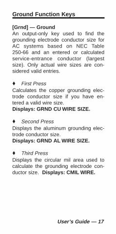
[Grnd] — Gr oundAn output-only key used to find thegrounding electrode conductor size forAC systems based on NEC Table 250-66 and an entered or calculatedservice-entrance conductor (largestsize). Only actual wire sizes are con-sidered valid entries.
♦ First PressCalculates the copper grounding elec-trode conductor size if you have en-tered a valid wire size. Displa ys: GRND CU WIRE SIZE.
♦ Second PressDisplays the aluminum grounding elec-trode conductor size. Displa ys: GRND AL WIRE SIZE.
♦ Third PressDisplays the circular mil area used tocalculate the grounding electrode con-ductor size. Displa ys: CMIL WIRE.
5060-UG-B-Composite 4/4/03 12:37 PM Page 19
18 — ElectriCalc Pro
[Set] [Grnd] — Equipment Gr ound (EqGrnd)This function uses NEC Table 250-122to compute the minimum equipmentgrounding conductor size, given anentered amperage rating or setting for aover-current device up line (i.e., 300[Set] [Grnd]).
NOTE: This function deviates from theNEC Table 250-122 in that 1250 MCMAL is used instead of 1200 as specifiedin NEC Table 250-122.
♦ First PressDisplays the copper grounding conduc-tor size for the entered amp rating.Displa ys: EQPG WIRE SIZE CU.
♦ Second PressDisplays the aluminum grounding con-ductor size. Displa ys: EQPG WIRE SIZE AL.
5060-UG-B-Composite 4/4/03 12:37 PM Page 20
User ’s Guide — 19
Fuse/Breaker K eys
The ElectriCalc Pro has special keysthat automatically calculate the Amp ratings of the following over-current protection devices: Dual Element Fuses(Time Delay), Single Element Fuses(Non-Time Delay), Instantaneous TripBreakers (Type 1), Inverse TimeBreakers (Type 2), and OverloadProtection Devices.
These fuse and circuit breaker sizes are derived using the “Percent of Full-Load Current” multipliers listed in NECTable 430-152.
You can also calculate the full voltagestarter size for non-plugging and non-jogging duty motors based on phase,voltage, motor HP and NEMA tablespecifications.
If a parameter is missing or invalid, thecalculator will display “nonE .”
[Set] [O-Load] — Motor Type Based on NEC Table 430-152, this keyselects the motor type used to define the percent factors for breakers/fuses.Once set, the motor type remains fixeduntil you change it or perform an all clear ([Set] [x] ).
5060-UG-B-Composite 4/4/03 12:37 PM Page 21
20 — ElectriCalc Pro
♦ First PressDisplays the current motor type. Notethere is no motor type in single-phasemode.
♦ Second PressIn three-phase mode only, subsequentpresses of [O-Load] will select and display the next motor type from this list: SQ-C non-E (Squirrel Cage, non-Design E), SQ-C E (Squirrel Cage,Design E), SYNC no codE (Synchro-nous), WND no codE (Wound Rotor).
[DEFuse] — Dual Element Fuse
♦ First PressCalculates the minimum amp rating for a Dual Element Fuse. Displa ys: AMPS dE.
♦ Second PressDisplays the full-load current percentmultiplier used to determine fuse size.Displa ys: %FLC.
[Set] [DEFuse]— Single Element Fuse (SEFuse)
♦ First PressDisplays the minimum amp rating based on phase, motor type, and am-perage. Displa ys: AMPS SE.
5060-UG-B-Composite 4/4/03 12:37 PM Page 22

User ’s Guide — 21
♦ Second PressDisplays the full-load current percentmultiplier value used to determine fusesize. Subsequent presses repeat thiscycle. Displa ys: %FLC.
[Set] [In vTime] — InstantaneousTrip Cir cuit Breaker
♦ First Press Displays the minimum amp rating for an Instantaneous Trip Circuit Breaker,based on the phase, motor type, andamperage. Displa ys: AMPS b1.
♦ Second PressDisplays the full-load current percentmultiplier value used to determinebreaker size. Displa ys: %FLC.
[InvTime] — In verse Time Breaker
♦ First PressCalculates the minimum amp rating foran Inverse Time Breaker, based on thephase, motor type, and amperage.Displa ys: AMPS b2.
♦ Second PressDisplays the full-load current percentmultiplier value used to determinebreaker size. Displa ys: %FLC.
5060-UG-B-Composite 4/4/03 12:37 PM Page 23
22 — ElectriCalc Pro
[O-Load] — Overload Pr otection
♦ First PressDisplays the overload amperage re-quirement based on the full-load cur-rent shown on the motor nameplate.Multiplies the entered motor nameplatefull-load current (stored in the [Amps]registers) by 115% or the value youenter. Conforms to NEC Section 430-32 (a)(1) value of 115% unless you enter another value. For example, en-tering 125 [O-Load] would calculateoverload protection based on 125% ofthe entered amperage. Displa ys:AMPS ol.
♦ Second PressDisplays the full-load current percentmultiplier value used to determine theoverload current protection size. Sub-sequent presses of [O-Load] repeat thecycle. Displa ys: %FLC.
[Set] [HPmotor] — Star ter Siz eDisplays the starter size (from NEMApublication ICS 2-1988 Tables 2-327-1and 2-327-2) based on the phase, volt-age, and motor horsepower settings.Displa ys: STAR SIZE.
NOTE: Horsepower values not identi-fied in NEMA tables will cause the cal-culator to round up to the next largerstarter size in the table.
5060-UG-B-Composite 4/4/03 12:37 PM Page 24
User ’s Guide — 23
Conduit Sizing K eys
The ElectriCalc Pro calculates conduitsize using NEC Tables 1, 3, 4, and 5 ofChapter 9 (given insulation type, wiresize, and quantity of wires). It will alsocalculate the number of wires of a specified insulation type and wire sizethat will fit in a defined conduit size.Acceptable conduit sizes (depending on the type of conduit used) are as follows: 1/2”, 3/4”, 1”, 1-1/4”, 1-1/2”, 2”,2-1/2”, 3”, 3-1/2”, 4” 5” and 6”. Conduitsizes are entered using decimal equiva-lents (i.e., 1-1/2” is entered as 1.5, 3/4”is entered as .75, etc.).
[#THW], [#XHHW], [#THHN]— Number of WiresUsed to enter or calculate the number of wires in a raceway and calculatecross-sectional wire area.
♦ First PressEnters number of wires or calculatesmaximum number of wires in conduit.Displa ys: TTL WIRES (calculated) orWIRES (entered).
♦ Second PressShows total cross-sectional area for allentered wires. Displa ys: WIRE AREA(entered) or TTL WIRE AREA (calcu-lated).
5060-UG-B-Composite 4/4/03 12:37 PM Page 25
24 — ElectriCalc Pro
♦ Third PressShows total cross-sectional area of allentered wires of the selected wire insu-lation. Displa ys: TTL WIRE AREA.
[CondSz] — Conduit Siz eUsed to find conduit sizes based on thetotal area of the entered wire types andsizes (up to 15 at one time). If the quantity and insulation type has not been entered, the calculator will as-sume 2 THHN wires for single-phase or3 THHN wires for three-phase calcula-tions.
♦ First PressEnters or calculates conduit size.Displa ys: COND SIZE.
NOTE: If a wire size has not been en-tered or calculated, or an invalid con-duit size is entered, the calculator willdisplay “nonE .”
♦ Second PressShows total number of wires in the conduit for calculated conduit size.Shows the conduit internal area for anentered conduit. Displa ys: TTL WIRES(calculated) or CONDAREA (entered).
NOTE: Third through fifth presses dis-play only for calculated conduit sizes.
5060-UG-B-Composite 4/4/03 12:37 PM Page 26
User ’s Guide — 25
♦ Third PressShows fill percentage for the calculatedconduit size as determined by Table 1,Chapter 9. Displa ys: COND FILL %.
♦ Fourth PressShows the total wire area for all enteredwires. Displa ys: FILL TTL WIRE AREA.
♦ Fifth PressShows remaining fill area. This valuemay be negative if all wires are thesame size due to Note 7 in NEC Chap-ter 9, Table 1. Displa ys: REM WIRE AREA.
[Set] [CondSz] — Conduit Type
♦ First PressDisplays the currently selected conduittype.
♦ Second PressSubsequent presses will display andselect the next conduit type from this list: 1) EMT 2) ENT 3) FMC 4) IMC 5) LFNB 6) LFNA 7) LFMC 8) RMC 9) P-80 10) P-40 11) P-A 12) P- EB. To select a specific conduit type, enterthe corresponding number of the con-duit and then press [Set] [CondSz]. Ifyou press this keystroke without enter-ing a number, the calculator will switchto the next conduit type on the list.
5060-UG-B-Composite 4/4/03 12:37 PM Page 27
26 — ElectriCalc Pro
Preference Settings
Your calculator has the following Pref-erence Settings that you can accessand change at any time.
Reach the Preference Function bypressing [Set] [ ÷]. Then, to access each category, press the [÷] key until the desired setting is reached. Withineach category, press the [+] or [-] keys to toggle between individual selections(note: the [+] will advance, the [-] willback-up).
You can change these settings at anytime by repeating the above, and set-ting in a new preference. NOTE: To clear preferences, you must either resetusing keystrokes below, or perform anAll-Clear ([Set] [x] ).
The Preference Settings are (defaultsettings shown first):
To Set 1999 or 1996 NEC Code:[Set] [÷] (1st press of [÷]) CODE 99[+] CODE 96To Set Ambient Temp. to °C or °F:[÷] (2nd press of [÷]) AMB° 30 °C[+] AMB° 86 °FTo Set Length to Feet or Meter:[÷] (3rd press of [÷]) FEET 1.[+] MET 1.
5060-UG-B-Composite 4/4/03 12:37 PM Page 28
User ’s Guide — 27
Default Settings
When you first receive your calculator, it is pre-set to the default settings listedbelow. You can always return your calculator to these default values withan All-Clear ([Set] [x] ).
Ambient Temperature 30°C
Insulation Rating 60°C
Material Copper (Cu)
Phase 3Ø
Volts 240 V
Efficiency 100%
Power Factor 100%
Length Units Feet
Voltage Drop Percent 3%
Wire Environment Raceway(vs Free Air)
5060-UG-B-Composite 4/4/03 12:37 PM Page 29
28 — ElectriCalc Pro
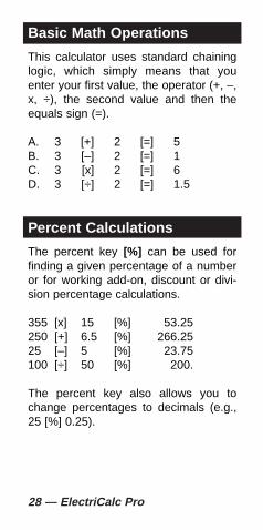
Basic Math Operations
This calculator uses standard chaininglogic, which simply means that you enter your first value, the operator (+, –, x, ÷), the second value and then theequals sign (=).
A. 3 [+] 2 [=] 5B. 3 [–] 2 [=] 1C. 3 [x] 2 [=] 6D. 3 [÷] 2 [=] 1.5
Percent Calculations
The percent key [%] can be used forfinding a given percentage of a numberor for working add-on, discount or divi-sion percentage calculations.
355 [x] 15 [%] 53.25250 [+] 6.5 [%] 266.2525 [–] 5 [%] 23.75100 [÷] 50 [%] 200.
The percent key also allows you tochange percentages to decimals (e.g.,25 [%] 0.25).
5060-UG-B-Composite 4/4/03 12:37 PM Page 30
User ’s Guide — 29
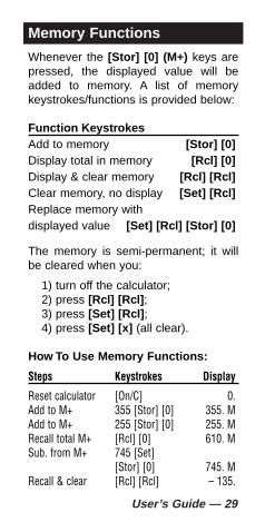
Memor y Functions
Whenever the [Stor] [0] (M+) keys arepressed, the displayed value will beadded to memory. A list of memory keystrokes/functions is provided below:
Function Keystr okesAdd to memory [Stor] [0]Display total in memory [Rcl] [0]Display & clear memory [Rcl] [Rc l]Clear memory, no display [Set] [Rc l]Replace memory withdisplayed value [Set] [Rc l] [Stor] [0]
The memory is semi-permanent; it willbe cleared when you:
1) turn off the calculator;2) press [Rcl] [Rc l] ;3) press [Set] [Rc l] ;4) press [Set] [x] (all clear).
How To Use Memor y Functions:
Steps Keystrokes Display
Reset calculator [On/C] 0.Add to M+ 355 [Stor] [0] 355. M Add to M+ 255 [Stor] [0] 255. M Recall total M+ [Rcl] [0] 610. M Sub. from M+ 745 [Set]
[Stor] [0] 745. M Recall & clear [Rcl] [Rcl] – 135.
5060-UG-B-Composite 4/4/03 12:37 PM Page 31
30 — ElectriCalc Pro
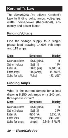
Kerchoff ’s Law
The ElectriCalc Pro utilizes Kerchoff’sLaw in finding volts, amps, volt-amps,watts, horsepower (theoretical), effi-ciency and power factor.
Finding Volta ge
Find the voltage supply to a single-phase load drawing 14,605 volt-ampsand 115 amps.
Steps Keystrokes Display
Clear calculator [On/C] [On/C] 0.Set to 1-phase [Set] [1] 1 PHEnter VA 14605 [VA] 14,605. VAEnter amps 115 [Amps] 115. AMPSSolve for volts [Volts] 127. VOLT
Finding Amps
What is the current (amps) for a loaddrawing 8,250 volt-amps on a 240 volt,three-phase circuit?Steps Keystrokes Display
Clear calculator [On/C] [On/C] 0.Set to 3-phase [Set] [3] 3 PHEnter VA 8250 [VA] 8,250. VAEnter volts 240 [Volts] 240. VOLTSolve for amps [Amps] 19.846416 AMPS
5060-UG-B-Composite 4/4/03 12:37 PM Page 32
User ’s Guide — 31
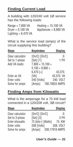
Finding Current Load
A building with 120/240 volt 1Ø servicehas the following loads:
Range = 7,800 VA Heating = 15,100 VADryer = 5,100 VA Appliances = 8,900 VALighting = 6,470 VA
What is the service load (amps) of thecircuit supplying this building?
Steps Keystrokes Display
Clear calculator [On/C] [On/C] 0.Set to 1-phase [Set] [1] 1 PHAdd VA loads: 7,800 + 15,100 +
5,100 + 8,900 + 6,470 [=] 43,370.
Enter as VA [VA] 43,370. VAEnter volts 240 [Volts] 240. VOLTSolve for amps [Amps] 180.70833 AMPS
Finding Amps fr om Kilo watts
What is the amperage for a 75 kW loadconnected in a 120/208 volt, 3Ø circuit?
Steps Keystrokes Display
Clear calculator [On/C] [On/C] 0.Set to 3-phase [Set] [3] 3 PHEnter kilowatts 75 [kilo-] [Watts] 75. KWEnter volts 208 [Volts] 208. VOLTSolve for amps [Amps] 208.17918 AMPS
5060-UG-B-Composite 4/4/03 12:37 PM Page 33
32 — ElectriCalc Pro
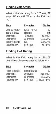
Finding Volt-Amps
What is the VA rating for a 120 volt, 22amp, 1Ø circuit? What is the kVA rat-ing?
Steps Keystrokes Display
Clear calculator [On/C] [On/C] 0.Set to 1-phase [Set] [1] 1 PHEnter volts 120 [Volts] 120. VOLTEnter amps 22 [Amps] 22. AMPSSolve volt-amps [VA] 2,640. VASolve for kVA [kilo-] [VA] 2.64 KVA
Finding kV A Rating
What is the kVA rating for a 120/208 volt, three-phase 65 amp transformer?
Steps Keystrokes Display
Reset calculator [Set] [x] [On/C] 0.Enter volts 208 [Volts] 208. VOLTEnter amps 65 [Amps] 65. AMPSSolve for kVA [kilo-] [VA] 23.417327 KVA
5060-UG-B-Composite 4/4/03 12:37 PM Page 34
User ’s Guide — 33
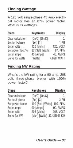
Finding Wattage
A 120 volt single-phase 45 amp electri-cal motor has an 87% power factor.What is its wattage?
Steps Keystrokes Display
Clear calculator [On/C] [On/C] 0.Set to 1-phase [Set] [1] 1 PHEnter volts 120 [Volts] 120. VOLTSet power fact % 87 [Set] [Watts] 87. PF%Enter amps 45 [Amps] 45. AMPSSolve for watts [Watts] 4,698. WATT
Finding kW Rating
What’s the kW rating for a 90 amp, 208volt, three-phase broiler with 100%power factor?
Steps Keystrokes Display
Clear calculator [On/C] [On/C] 0.Set to 3-phase [Set] [3] 3 PHSet power factor 100 [Set] [Watts] 100. PF%Enter amps 90 [Amps] 90. AMPSEnter volts 208 [Volts] 208. VOLTSolve for kW [kilo-] [Watts] 32.423991 KW
5060-UG-B-Composite 4/4/03 12:37 PM Page 35
34 — ElectriCalc Pro
Motor Hor sepo wer
The ElectriCalc Pro can calculate the full load current (amps) of a motor,based on phase, voltage and motor(synchronous or induction). It uses NEC Tables 430-148 and 430-150 todetermine the motor full load current. (Ifyou enter a value for HP or voltage thatdoes not correspond to these tables, the unit will display Error 8).
The ElectriCalc Pro can also calculatean equivalent horsepower for either aninduction or a synchronous motor based on a voltage, phase and full loadcurrent. When calculating motor HPfrom an entered amperage, a result notdirectly matching a value in NEC Table430-148 or 430-150 will cause the cal-culator to choose the next higher tablevalue for motor horsepower.
5060-UG-B-Composite 4/4/03 12:37 PM Page 36
User ’s Guide — 35
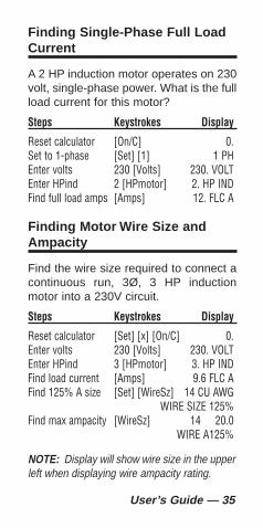
Finding Single-Phase Full LoadCurrent
A 2 HP induction motor operates on 230volt, single-phase power. What is the fullload current for this motor?
Steps Keystrokes Display
Reset calculator [On/C] 0.Set to 1-phase [Set] [1] 1 PHEnter volts 230 [Volts] 230. VOLTEnter HPind 2 [HPmotor] 2. HP INDFind full load amps [Amps] 12. FLC A
Finding Motor Wire Siz e andAmpacity
Find the wire size required to connect acontinuous run, 3Ø, 3 HP inductionmotor into a 230V circuit.
Steps Keystrokes Display
Reset calculator [Set] [x] [On/C] 0.Enter volts 230 [Volts] 230. VOLTEnter HPind 3 [HPmotor] 3. HP INDFind load current [Amps] 9.6 FLC AFind 125% A size [Set] [WireSz] 14 CU AWG
WIRE SIZE 125%Find max ampacity [WireSz] 14 20.0
WIRE A125%
NOTE: Display will show wire size in the upperleft when displaying wire ampacity rating.
5060-UG-B-Composite 4/4/03 12:37 PM Page 37
36 — ElectriCalc Pro
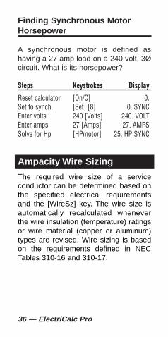
Finding Sync hronous MotorHorsepo wer
A synchronous motor is defined as having a 27 amp load on a 240 volt, 3Øcircuit. What is its horsepower?
Steps Keystrokes Display
Reset calculator [On/C] 0.Set to synch. [Set] [8] 0. SYNCEnter volts 240 [Volts] 240. VOLTEnter amps 27 [Amps] 27. AMPSSolve for Hp [HPmotor] 25. HP SYNC
Ampacity Wire Sizing
The required wire size of a service conductor can be determined based onthe specified electrical requirements and the [WireSz] key. The wire size isautomatically recalculated whenever the wire insulation (temperature) ratingsor wire material (copper or aluminum)types are revised. Wire sizing is basedon the requirements defined in NECTables 310-16 and 310-17.
5060-UG-B-Composite 4/4/03 12:37 PM Page 38
User ’s Guide — 37
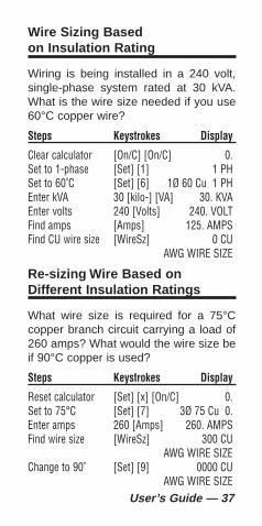
Wire Sizing Based on Insulation Rating
Wiring is being installed in a 240 volt,single-phase system rated at 30 kVA.What is the wire size needed if you use60°C copper wire?
Steps Keystrokes Display
Clear calculator [On/C] [On/C] 0.Set to 1-phase [Set] [1] 1 PHSet to 60˚C [Set] [6] 1Ø 60 Cu 1 PHEnter kVA 30 [kilo-] [VA] 30. KVAEnter volts 240 [Volts] 240. VOLTFind amps [Amps] 125. AMPSFind CU wire size [WireSz] 0 CU
AWG WIRE SIZE
Re-sizing Wire Based on Diff erent Insulation Ratings
What wire size is required for a 75°Ccopper branch circuit carrying a load of260 amps? What would the wire size beif 90°C copper is used?
Steps Keystrokes Display
Reset calculator [Set] [x] [On/C] 0.Set to 75°C [Set] [7] 3Ø 75 Cu 0.Enter amps 260 [Amps] 260. AMPSFind wire size [WireSz] 300 CU
AWG WIRE SIZEChange to 90˚ [Set] [9] 0000 CU
AWG WIRE SIZE
5060-UG-B-Composite 4/4/03 12:37 PM Page 39
38 — ElectriCalc Pro
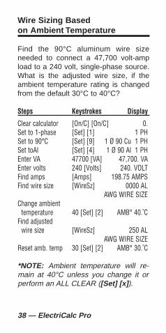
Wire Sizing Basedon Ambient Temperature
Find the 90°C aluminum wire size needed to connect a 47,700 volt-ampload to a 240 volt, single-phase source.What is the adjusted wire size, if theambient temperature rating is changedfrom the default 30°C to 40°C?
Steps Keystrokes Display
Clear calculator [On/C] [On/C] 0.Set to 1-phase [Set] [1] 1 PHSet to 90°C [Set] [9] 1 Ø 90 Cu 1 PHSet toAl [Set] [4] 1 Ø 90 Al 1 PHEnter VA 47700 [VA] 47,700. VAEnter volts 240 [Volts] 240. VOLTFind amps [Amps] 198.75 AMPSFind wire size [WireSz] 0000 AL
AWG WIRE SIZEChange ambient
temperature 40 [Set] [2] AMB° 40.˚CFind adjusted
wire size [WireSz] 250 ALAWG WIRE SIZE
Reset amb. temp 30 [Set] [2] AMB° 30.˚C
*NOTE: Ambient temperature will re-main at 40°C unless you change it orperform an ALL CLEAR ([Set] [x] ).
5060-UG-B-Composite 4/4/03 12:37 PM Page 40
User ’s Guide — 39
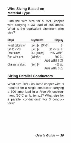
Wire Sizing Based on Material Type
Find the wire size for a 75°C copper wire carrying a 3Ø load of 265 amps.What is the equivalent aluminum wiresize?
Steps Keystrokes Display
Reset calculator [Set] [x] [On/C] 0.Set to 75°C [Set] [7] 3Ø 75 Cu 0.Enter amps 265 [Amps] 265. AMPSFind wire size [WireSz] 300 CU
AWG WIRE SIZEChange to alum. [Set] [4] 400 AL
AWG WIRE SIZE
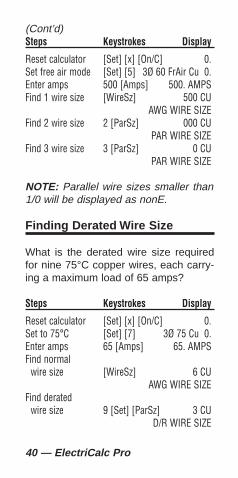
Sizing P arallel Conductor s
What size 60°C insulated copper wire isrequired for a single conductor carryinga 500 amp load in a Free Air environ-ment (30°C amb. temp.)? What size for2 parallel conductors? For 3 conduc-tors?
5060-UG-B-Composite 4/4/03 12:37 PM Page 41
40 — ElectriCalc Pro
(Cont’d)Steps Keystrokes Display
Reset calculator [Set] [x] [On/C] 0.Set free air mode [Set] [5] 3Ø 60 FrAir Cu 0.Enter amps 500 [Amps] 500. AMPSFind 1 wire size [WireSz] 500 CU
AWG WIRE SIZEFind 2 wire size 2 [ParSz] 000 CU
PAR WIRE SIZEFind 3 wire size 3 [ParSz] 0 CU
PAR WIRE SIZE
NOTE: Parallel wire sizes smaller than1/0 will be displayed as nonE.
Finding Derated Wire Siz e
What is the derated wire size requiredfor nine 75°C copper wires, each carry-ing a maximum load of 65 amps?
Steps Keystrokes Display
Reset calculator [Set] [x] [On/C] 0.Set to 75°C [Set] [7] 3Ø 75 Cu 0.Enter amps 65 [Amps] 65. AMPSFind normal
wire size [WireSz] 6 CUAWG WIRE SIZE
Find deratedwire size 9 [Set] [ParSz] 3 CU
D/R WIRE SIZE
5060-UG-B-Composite 4/4/03 12:37 PM Page 42
User ’s Guide — 41
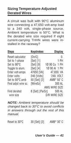
Sizing Temperature-AdjustedDerated Wires
A circuit was built with 90°C aluminumwire connecting a 47,650 volt-amp loadto a 240 volt, single-phase source.Ambient temperature is 50°C. What isthe derated wire size required if eightcurrent-carrying THHN wires were in-stalled in the raceway?
Steps Keystrokes Display
Reset calculator [On/C] 0.Set to 1-phase [Set] [1] 1 PHSet to 90°C [Set] [9] 1Ø 90 Cu 1 PHToggle to alum. [Set] [4] 1Ø 90 Al 1 PHEnter volt-amps 47650 [VA] 47,650. VAEnter volts 240 [Volts] 240. VOLTSet to 50°C amb 50 [Set] [2] AMB° 50˚ CFind adjst wire sz. [WireSz] 300 AL
AWG WIRE SIZEFind derated 8 [Set] [ParSz] 500 AL
wire size D/R WIRE SIZE
NOTE: Ambient temperature should bechanged back to 30°C to avoid conflictsin answers through out the rest of thismanual.
Reset to 30°C 30 [Set] [2] AMB° 30˚ C
5060-UG-B-Composite 4/4/03 12:37 PM Page 43
42 — ElectriCalc Pro
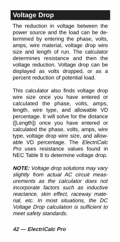
Volta ge Drop
The reduction in voltage between thepower source and the load can be de-termined by entering the phase, volts,amps, wire material, voltage drop wiresize and length of run. The calculatordetermines resistance and then the voltage reduction. Voltage drop can bedisplayed as volts dropped, or as a percent reduction of potential load.
This calculator also finds voltage dropwire size once you have entered or calculated the phase, volts, amps,length, wire type, and allowable VD percentage. It will solve for the distance([Length]) once you have entered or calculated the phase, volts, amps, wiretype, voltage drop wire size, and allow-able VD percentage. The ElectriCalcPro uses resistance values found inNEC Table 8 to determine voltage drop.
NOTE: Voltage drop solutions may varyslightly from actual AC circuit meas-urements as the calculator does not incorporate factors such as inductivereactance, skin effect, raceway mate-rial, etc. In most situations, the DCVoltage Drop calculation is sufficient tomeet safety standards.
5060-UG-B-Composite 4/4/03 12:37 PM Page 44

User ’s Guide — 43
IMPORTANT NOTE ON VOLTAGE DROP CALCULATIONS
The ElectriCalc Pro calculates voltagedrop and wire size using DC resistanceas defined by the 2002 NEC. To find the voltage drop for a specific wire size,you must first enter amps and the one-way wire length (and other required variables), entering the specific wire size last. Otherwise, for your safety thecalculator will recalculate the wire sizesbased on the ‘99 NEC Ampacity Tablesand maximum allowable voltage drop.
Finding Single-Phase Voltage Drop
You are installing 175 feet of 75°C, #8THW branch circuit copper conductorsto supply an 11A load on a 208V 1Ø system. What is the source voltage drop at the load?
Steps Keystrokes Display
Reset calculator [Set] [x] [On/C] 0.Set to 1-phase [Set] [1] 1 PHSet to 75°C [Set] [7] 1Ø 75 Cu 1 PHEnter amps 11 [Amps] 11. AMPSEnter volts 208 [Volts] 208. VOLTEnter length 175 [Length] 175. FEETEnter wire size 8 [WireSz] 8 CU
AWG WIRE SIZESolve volt. drop [VD%] 3.0 DROP VSolve % v.drop [VD%] 1.4 DROP V %
5060-UG-B-Composite 4/4/03 12:37 PM Page 45
44 — ElectriCalc Pro
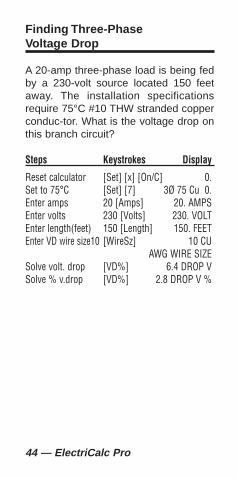
Finding Three-Phase Volta ge Drop
A 20-amp three-phase load is being fedby a 230-volt source located 150 feetaway. The installation specificationsrequire 75°C #10 THW stranded copperconduc-tor. What is the voltage drop onthis branch circuit?
Steps Keystrokes Display
Reset calculator [Set] [x] [On/C] 0.Set to 75°C [Set] [7] 3Ø 75 Cu 0.Enter amps 20 [Amps] 20. AMPSEnter volts 230 [Volts] 230. VOLTEnter length(feet) 150 [Length] 150. FEETEnter VD wire size10 [WireSz] 10 CU
AWG WIRE SIZESolve volt. drop [VD%] 6.4 DROP VSolve % v.drop [VD%] 2.8 DROP V %
5060-UG-B-Composite 4/4/03 12:37 PM Page 46
User ’s Guide — 45
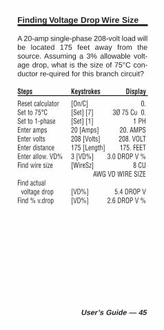
Finding Volta ge Drop Wire Siz e
A 20-amp single-phase 208-volt load willbe located 175 feet away from thesource. Assuming a 3% allowable volt-age drop, what is the size of 75°C con-ductor re-quired for this branch circuit?
Steps Keystrokes Display
Reset calculator [On/C] 0.Set to 75°C [Set] [7] 3Ø 75 Cu 0.Set to 1-phase [Set] [1] 1 PHEnter amps 20 [Amps] 20. AMPSEnter volts 208 [Volts] 208. VOLTEnter distance 175 [Length] 175. FEETEnter allow. VD% 3 [VD%] 3.0 DROP V %Find wire size [WireSz] 8 CU
AWG VD WIRE SIZEFind actual
voltage drop [VD%] 5.4 DROP VFind % v.drop [VD%] 2.6 DROP V %
5060-UG-B-Composite 4/4/03 12:37 PM Page 47
46 — ElectriCalc Pro
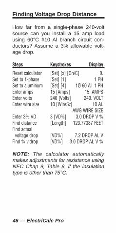
Finding Volta ge Drop Distance
How far from a single-phase 240-voltsource can you install a 15 amp loadusing 60°C #10 Al branch circuit con-ductors? Assume a 3% allowable volt-age drop.
Steps Keystrokes Display
Reset calculator [Set] [x] [On/C] 0.Set to 1-phase [Set] [1] 1 PHSet to aluminum [Set] [4] 1Ø 60 Al 1 PHEnter amps 15 [Amps] 15. AMPSEnter volts 240 [Volts] 240. VOLTEnter wire size 10 [WireSz] 10 AL
AWG WIRE SIZEEnter 3% VD 3 [VD%] 3.0 DROP V %Find distance [Length] 123.77387 FEETFind actual
voltage drop [VD%] 7.2 DROP AL VFind % v.drop [VD%] 3.0 DROP AL V %
NOTE: The calculator automaticallymakes adjustments for resistance usingNEC Chap 9, Table 8, if the insulationtype is other than 75°C.
5060-UG-B-Composite 4/4/03 12:37 PM Page 48
User ’s Guide — 47
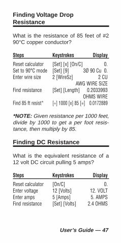
Finding Volta ge DropResistance
What is the resistance of 85 feet of #290°C copper conductor?
Steps Keystrokes Display
Reset calculator [Set] [x] [On/C] 0.Set to 90°C mode [Set] [9] 3Ø 90 Cu 0.Enter wire size 2 [WireSz] 2 CU
AWG WIRE SIZEFind resistance [Set] [Length] 0.2033993
OHMS WIREFind 85 ft resist* [÷] 1000 [x] 85 [=] 0.0172889
*NOTE: Given resistance per 1000 feet,divide by 1000 to get a per foot resis-tance, then multiply by 85.
Finding DC Resistance
What is the equivalent resistance of a 12 volt DC circuit pulling 5 amps?
Steps Keystrokes Display
Reset calculator [On/C] 0.Enter voltage 12 [Volts] 12. VOLTEnter amps 5 [Amps] 5. AMPSFind resistance [Set] [Volts] 2.4 OHMS
5060-UG-B-Composite 4/4/03 12:37 PM Page 49
48 — ElectriCalc Pro
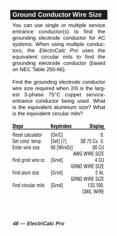
Ground Conductor Wire Siz e
You can use single or multiple serviceentrance conductor(s) to find thegrounding electrode conductor for ACsystems. When using multiple conduc-tors, the ElectriCalc Pro uses the equivalent circular mils to find thegrounding electrode conductor (basedon NEC Table 250-66).
Find the grounding electrode conductorwire size required when 2/0 is the larg-est 3-phase 75°C copper service-entrance conductor being used. What is the equivalent aluminum size? Whatis the equivalent circular mils?
Steps Keystrokes Display
Reset calculator [On/C] 0.Set cond. temp. [Set] [7] 3Ø 75 Cu 0.Enter wire size 00 [WireSz] 00 CU
AWG WIRE SIZEFind grnd wire sz [Grnd] 4 CU
GRND WIRE SIZEFind alum size [Grnd] 2 AL
GRND WIRE SIZEFind circular mils [Grnd] 133,100.
CMIL WIRE
5060-UG-B-Composite 4/4/03 12:37 PM Page 50
User ’s Guide — 49
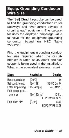
Equip. Grounding ConductorWire Siz e
The [Set] [Grnd] keystroke can be used to find the grounding conductor size forraceways and “over-current devices incircuit ahead” equipment. The calcula-tor uses the displayed amperage valueto solve for the equipment groundingconductor based on NEC Table 250-122.
Find the equipment grounding conduc-tor size required when the circuit-breaker is rated at 45 amps and 90°copper is being used in the installation.What is the equivalent aluminum size?
Steps Keystrokes Display
Reset calculator [On/C] 0.Set cond. temp. [Set] [9] 3Ø 90 Cu 0.Enter amp rating 45 [Amps] 45. AMPSFind equip. grnd.
wire size [Set] [Grnd] 10 CUEQPG WIRE SIZE
Find alum size [Grnd] 8 ALEQPG WIRE SIZE
5060-UG-B-Composite 4/4/03 12:37 PM Page 51
50 — ElectriCalc Pro
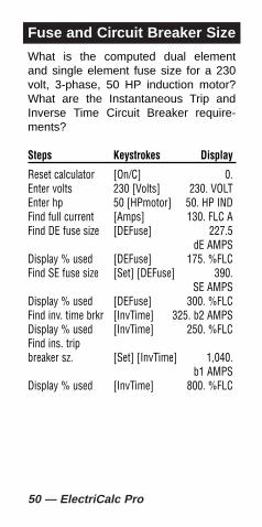
Fuse and Cir cuit Breaker Siz e
What is the computed dual element and single element fuse size for a 230volt, 3-phase, 50 HP induction motor?What are the Instantaneous Trip andInverse Time Circuit Breaker require-ments?
Steps Keystrokes Display
Reset calculator [On/C] 0.Enter volts 230 [Volts] 230. VOLTEnter hp 50 [HPmotor] 50. HP INDFind full current [Amps] 130. FLC AFind DE fuse size [DEFuse] 227.5
dE AMPSDisplay % used [DEFuse] 175. %FLCFind SE fuse size [Set] [DEFuse] 390.
SE AMPSDisplay % used [DEFuse] 300. %FLCFind inv. time brkr [InvTime] 325. b2 AMPSDisplay % used [InvTime] 250. %FLCFind ins. trip breaker sz. [Set] [InvTime] 1,040.
b1 AMPSDisplay % used [InvTime] 800. %FLC
5060-UG-B-Composite 4/4/03 12:37 PM Page 52
User ’s Guide — 51
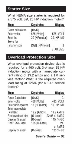
Star ter Siz e
What NEMA size starter is required for a 575 volt, 3Ø, 20 HP induction motor?
Steps Keystrokes Display
Reset calculator [On/C] 0.Enter volts 575 [Volts] 575. VOLTEnter hp 20 [HPmotor] 20. HP INDSolve for
starter size [Set] [HPmotor] 2STAR SIZE
Overload Pr otection Siz e
What overload protection device size isrequired for a 460 volt, 3-phase, 15 HPinduction motor with a nameplate cur-rent rating of 19.2 amps and a 1.0 ser-vice factor? What is the required over-load rating at 125% (for a 1.15 servicefactor)?
Steps Keystrokes Display
Reset Calculator [On/C] 0.Enter volts 460 [Volts] 460. VOLTEnter horsepower 15 [HPmotor] 15. HP INDEnter nameplate
current 19.2 [Amps] 19.2 AMPSFind overload size [O-Load] 22.08 ol AMPSDisplay % used [O-Load] 115. %FLCFind 125% load 125 [O-Load] 24.
ol AMPSDisplay % used [O-Load] 125 %FLC
5060-UG-B-Composite 4/4/03 12:37 PM Page 53
52 — ElectriCalc Pro
Conduit Siz e
The ElectriCalc Pro can calculate thesize of conduit required when runningsingle or multiple wires using the[CondSz] key and the calculator’s inter-nal tables. The calculator uses NEC values for area of THW, THHN, andXHHW wires. When using the actualwire areas (and following the guidelines in NEC Chapter 9, Tables 1, 3, 4 and 5), the calculator can calculate a con-duit size based on the conduit type and the same or different wire types andsizes.
To select a specific conduit type, enterthe corresponding number of the con-duit and then press [Set] [CondSz]. Thenumbers and types are:
1) EMT 2) ENT 3) FMC 4) IMC5) LFNB 6) LFNA 7) LFMC 8) RMC9) P-80 10) P-40 11) P-A 12) P-EB
When you enter a new conduit type orscroll through the types, you will see the updated conduit size (if you have entered the wire type and quantity).
5060-UG-B-Composite 4/4/03 12:37 PM Page 54
User ’s Guide — 53
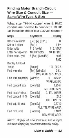
Finding Motor Branc h-Cir cuitWire Siz e & Conduit Siz e —Same Wire Type & Siz e
What size THHN copper wire & RMCconduit are needed to connect a 10 HP1Ø induction motor to a 115 volt source?
Steps Keystrokes Display
Reset calculator [Set] [x] [On/C] 0.Set to 1-phase [Set] 1 1 PHEnter volts 115 [Volts] 115. VOLTEnter horsepower 10 [HPmotor] 10. HP INDEnter cond. type 8 [Set] [CondSz] nonE
RMCDisplay full loadamps [Amps] 100. FLC A
Find wire size [Set] [WireSz] 0 CUAWG WIRE SIZE 125%
Find wire ampacity [WireSz] 0 125.0*WIRE A125%
Find conduit size [CondSz] 1.25 inRMC COND SIZE
Find total # wires [CondSz] 2. TTL WIRESFind conduit fill % [CondSz] 24.3
FILL COND %Find act. fill area [CondSz] 0.3710
FILL TTL WIRE AREAFind rem. area [CondSz] 0.1021
REM WIRE AREA
NOTE: Display will also show wire size in upperleft when displaying maximum ampacity rating.
5060-UG-B-Composite 4/4/03 12:37 PM Page 55
54 — ElectriCalc Pro
NOTE: If a wire size has been calculated orstored, and the wire type/quantity is not defined,the calculator will assume 2 THHN wires for 1Øand 3 THHN wires for 3Ø when calculating conduit size.
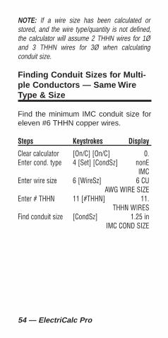
Finding Conduit Siz es for Multi-ple Conductor s — Same WireType & Siz e
Find the minimum IMC conduit size foreleven #6 THHN copper wires.
Steps Keystrokes Display
Clear calculator [On/C] [On/C] 0.Enter cond. type 4 [Set] [CondSz] nonE
IMCEnter wire size 6 [WireSz] 6 CU
AWG WIRE SIZEEnter # THHN 11 [#THHN] 11.
THHN WIRESFind conduit size [CondSz] 1.25 in
IMC COND SIZE
5060-UG-B-Composite 4/4/03 12:37 PM Page 56
User ’s Guide — 55
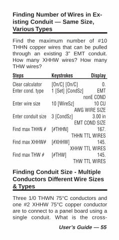
Finding Number of Wires in Ex-isting Conduit — Same Siz e,Various Types
Find the maximum number of #10 THHN copper wires that can be pulledthrough an existing 3” EMT conduit.How many XHHW wires? How manyTHW wires?
Steps Keystrokes Display
Clear calculator [On/C] [On/C] 0.Enter cond. type 1 [Set] [CondSz] EMT
nonE COND Enter wire size 10 [WireSz] 10 CU
AWG WIRE SIZEEnter conduit size 3 [CondSz] 3.00 in
EMT COND SIZEFind max THHN # [#THHN] 167.
THHN TTL WIRESFind max XHHW# [#XHHW] 145.
XHHW TTL WIRESFind max THW # [#THW] 145.
THW TTL WIRES
Finding Conduit Siz e - MultipleConductor s Diff erent Wire Siz es& Types
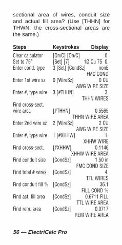
Three 1/0 THWN 75°C conductors andone #2 XHHW 75°C copper conductorare to connect to a panel board using asingle conduit. What is the cross-
5060-UG-B-Composite 4/4/03 12:37 PM Page 57
56 — ElectriCalc Pro
sectional area of wires, conduit size and actual fill area? (Use [THHN] forTHWN; the cross-sectional areas arethe same.)
Steps Keystr okes Displa y
Clear calculator [On/C] [On/C] 0.Set to 75° [Set] [7] 1Ø Cu 75 0.Enter cond. type 3 [Set] [CondSz] nonE
FMC CONDEnter 1st wire sz 0 [WireSz] 0 CU
AWG WIRE SIZEEnter #, type wire 3 [#THHN] 3.
THHN WIRESFind cross-sect.wire area [#THHN] 0.5565
THHN WIRE AREAEnter 2nd wire sz 2 [WireSz] 2 CU
AWG WIRE SIZEEnter #, type wire 1 [#XHHW] 1.
XHHW WIREFind cross-sect. [#XHHW] 0.1146
XHHW WIRE AREAFind conduit size [CondSz] 1.50 in
FMC COND SIZEFind total # wires [CondSz] 4.
TTL WIRESFind conduit fill % [CondSz] 36.1
FILL COND %Find act. fill area [CondSz] 0.6711 FILL
TTL WIRE AREAFind rem. area [CondSz] 0.0717
REM WIRE AREA
5060-UG-B-Composite 4/4/03 12:37 PM Page 58
User ’s Guide — 57
Error Codes
The error codes for the ElectriCalc Proare listed below (Note: To clear an error, simply press any key):
Error Description1 Display register overflow
(Answer too large to fit display)
2 Invalid or out-of-scale entry
3 PF or EFF calculated above 100%
4 Conduit Size beyond limits of table
5 Unable to calculate VDWire Size(Amps/Length too high)
8 Invalid HP entry per NEC table
9 Entered or calculated more than 15different wires sizes
11 Temperature setting out of range forwire computation.
Batter y Inf ormation
The calculator is powered by a single 3-Volt Lithium CR-2032 battery. Thisshould last upwards of 800 hours ofactual use (1 year plus for most peo-ple). If the display becomes very dim orerratic, replace the battery.
NOTE: Please use caution when dis-pos-ing of your old batteries as they contain hazardous chemicals.
5060-UG-B-Composite 4/4/03 12:37 PM Page 59
58 — ElectriCalc Pro
2002 NEC References
Table 250-66 Table 250-122Table 310-15(b)(2)(a)Table 310-16 Table 310-17Chapter 9, Table 1, 4, 5 and 8Section 430-32 Table 430-148Table 430-150 Table 430-152Appendix C
Updating Future Code Revisions
This model is updateable for future NEC Editions. For information on 2005and 2008 Codes, contact the dealerwhere this calculator was purchased oryou may contact Calculated Industries,Inc. in the fall of the year prior.
5060-UG-B-Composite 4/4/03 12:37 PM Page 60
User ’s Guide — 59
Settings
Permanent Values/Settings
Values and settings maintained in per-manent memory can only be changed(1) by pressing [Set] [x] (resets calcula-tor to default settings), or (2) by chang-ing each one or all of these settings. The following are permanent values:
(1) Selectable (60°C/75°C/90°C) insula-tion ratings and CU/AL wire type rat-ings
(2) Phase setting (1Ø/3Ø)(3) The entered values for volts, volt-
age drop %, power factor % and efficiency %
Semi-Permanent Values
The following semi-permanent valuesare cleared to default settings when thecalculator is shut off:
(1) Independent User Memory(2) Free Air mode
5060-UG-B-Composite 4/4/03 12:37 PM Page 61
60 — ElectriCalc Pro
Warranty
Warranty Repair Ser vice – U.S.A.Calculated Industries, Inc. (“CI”) war-rants this product against defects inmaterials and workmanship for a periodof one (1) year from the date of originalconsumer purchase in the U.S. If adefect exists during the warranty pe-riod, CI at its option will either repair(using new or remanufactured parts) orreplace (with a new or remanufacturedunit) the product at no charge.
THE WARRANTY WILL NOT APPLY TOTHE PRODUCT IF IT HAS BEEN DAM-AGED BY MISUSE, ALTERA-TION, ACCIDENT, IMPROPER HAN-DLING OR OPERATION, OR IF UN-AUTHORIZED REPAIRS ARE AT-TEMPTED OR MADE. SOME EXAM-PLES OF DAMAGES NOT COVEREDBY WARRANTY INCLUDE, BUT ARENOT LIMITED TO, BATTERY LEAK-AGE, BENDING, OR VISIBLE CRACK-ING OF THE LCD, WHICH ARE PRE-SUMED TO BE DAMAGES RESULT-ING FROM MISUSE OR ABUSE.
To obtain warranty service in the U.S.,ship the product postage paid to the CIAuthorized Service Provider listed onthe back page of the User’s Guide.
5060-UG-B-Composite 4/4/03 12:37 PM Page 62
User ’s Guide — 61
Please provide an explanation of theservice requirement, your name, ad-dress, day phone number and datedproof of purchase (typically a salesreceipt). If the product is over 90 daysold, include payment of $6.95 for returnshipping and handling within the con-tiguous 48 states. (Outside the contigu-ous 48 states, please call CI for returnshipping costs.)
A repaired or replacement productassumes the remaining warranty of theoriginal product or 90 days, whichever is longer.
Non-Warranty Repair Ser vice –U.S.A.Non-warranty repair covers servicebeyond the warranty period or servicerequested due to damage resulting from misuse or abuse.
Contact the CI Authorized Service Pro-vider listed on the back page of theUser’s Guide to obtain current productrepair information and charges. Repairsare guaranteed for 90 days.
5060-UG-B-Composite 4/4/03 12:37 PM Page 63

62 — ElectriCalc Pro
Repair Ser vice – Outside the U .S.A.Not all countries have CI AuthorizedService Providers or the same warrantyand service policies. To obtain warrantyor non-warranty repair service for goodspurchased outside the U.S., contact thedealer through which you initially pur-chased the product. If you cannot rea-sonably have the product repaired inyour area, you may contact CI to obtaincurrent product repair information andcharges, including freight and duties.
Disc laimer
CI MAKES NO WARRANTY OR REP-RESENTATION, EITHER EXPRESSOR IMPLIED, WITH RESPECT TO THE PRODUCT’S QUALITY, PER-FORMANCE, MERCHANTABILITY, OR FITNESS FOR A PARTICULARPURPOSE. AS A RESULT, THIS PRODUCT, INCLUDING BUT NOTLIMITED TO, KEYSTROKE PROCE-DURES, MATHEMATICAL ACCU-RACY AND PREPROGRAMMED MA-TERIAL, IS SOLD “AS IS,” AND YOUTHE PURCHASER ASSUME THEENTIRE RISK AS TO ITS QUALITYAND PERFORMANCE.
IN NO EVENT WILL CI BE LIABLE FOR DIRECT, INDIRECT, SPECIAL,
5060-UG-B-Composite 4/4/03 12:37 PM Page 64
User ’s Guide — 63
INCIDENTAL, OR CONSEQUENTIALDAMAGES RESULTING FROM ANYDEFECT IN THE PRODUCT OR ITSDOCUMENTATION.
The warranty, disclaimer, and remediesset forth above are exclusive and re-place all others, oral or written, ex-pressed or implied. No CI dealer, agent, or employee is authorized tomake any modification, extension, oraddition to this warranty.
Some states do not allow the exclusionor limitation of implied warranties or liability for incidental or consequentialdamages, so the above limitation orexclusion may not apply to you. Thiswarranty gives you specific rights, andyou may also have other rights, whichvary, from state to state.
FCC Class B
This equipment has been certified tocomply with the limits for a Class B computing device, pursuant to Subpart J of Part 15 of FCC rules.
5060-UG-B-Composite 4/4/03 12:37 PM Page 65

64 — ElectriCalc Pro
Legal Notices
Software copyrighted and licensed toCalculated Industries, Inc. by SpecialtyCalculator Technologies, LLC, 2002.
User’s Guide is copyrighted by Calcu-lated Industries, Inc., 2002.
ElectriCalc and Calculated Industriesare registered trademarks of CalculatedIndustries, Inc.
ALL RIGHTS RESERVED
Calculated Industries, Inc.4840 Hytec h Drive
Carson City , NV 89706 U.S.A775/885-4975 o Fax: 775/885-4949E-mail: [email protected]
http://www .calculated.com
File: 5060-UG-B
5060-UG-B-Composite 4/4/03 12:37 PM Page 66

5060-UG-B-Composite 4/4/03 12:37 PM Page 67

Printed in China5060-UG-B • 2/02
5060-UG-B-Composite 4/4/03 12:37 PM Page 68


![Introduction mod-gaussian convergencekowalski/mod-phi-new.pdf · 1. Introduction In [16], the notion of mod-gaussian convergence was introduced: intuitively, it corresponds to a sequence](https://static.fdocument.org/doc/165x107/5edc9d5dad6a402d66675b07/introduction-mod-gaussian-convergence-kowalskimod-phi-newpdf-1-introduction.jpg)