4.7pJ/pulse 7 Derivative Gaussian Pulse Generator for...
13
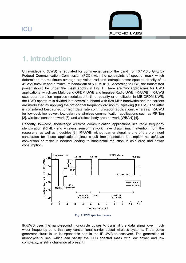
ICU 4.7pJ/pulse 7 th Derivative Gaussian Pulse Generator for Impulse Radio UWB Tuan-Anh Phan *, Student Member, IEEE, Vladimir Krizhanovskii *, Seok-Kyun Han *, and Sang-Gug Lee *, Member, IEEE, and Nae-Soo Kim ** * μ-Radio Lab, School of Engineering, Information and Communications University (ICU), 119 Munjiro, Yuseong-gu, Daejeon 305- 732, Korea. [email protected] ** Electronics and Telecommunication Research Institute (ETRI), Daejeon 305- 350, Korea. Auto-ID Labs White Paper WP-HARDWARE-040 Abstract—This paper presents a ultra low-power, low-complexity circuit to generate the monocycle pulse for Impulse Radio UWB (IR-UWB) applications. A 7th order derivative Gaussian pulse is generated using the edge combination technique plus an extra derivative circuitry. The proposed pulse generator is designed using TSMC 0.18 μm CMOS process. Simulation shows 500 mV of pulse amplitude and 800 ps of the pulse duration. Generated pulse spectrum fully complies with the FCC spectrum mask for out-door applications, especially in the range of 3.1–5.1 GHz. The pulse generator dissipates no static current with only dynamic energy consumption of around 4.7 pJ per pulse from 1.5 V supply. Keywords—Gaussian pulse generator, 7 th derivative, Impulse radio, Ultra wideband, Low power, Low complexity. Hardware
Transcript of 4.7pJ/pulse 7 Derivative Gaussian Pulse Generator for...
ICU
4.7pJ/pulse 7th Derivative Gaussian Pulse Generator for Impulse Radio UWB Tuan-Anh Phan *, Student Member, IEEE, Vladimir Krizhanovskii *, Seok-Kyun Han *, and Sang-Gug Lee *, Member, IEEE, and Nae-Soo Kim ** * μ-Radio Lab, School of Engineering,
Information and Communications University (ICU),
119 Munjiro, Yuseong-gu, Daejeon 305- 732, Korea.
** Electronics and Telecommunication Research Institute (ETRI), Daejeon 305- 350, Korea.
Auto-ID Labs White Paper WP-HARDWARE-040
Abstract—This paper presents a ultra low-power, low-complexity circuit to generate the monocycle pulse for Impulse Radio UWB (IR-UWB) applications. A 7th order derivative Gaussian pulse is generated using the edge combination technique plus an extra derivative circuitry. The proposed pulse generator is designed using TSMC 0.18 μm CMOS process. Simulation shows 500 mV of pulse amplitude and 800 ps of the pulse duration. Generated pulse spectrum fully complies with the FCC spectrum mask for out-door applications, especially in the range of 3.1–5.1 GHz. The pulse generator dissipates no static current with only dynamic energy consumption of around 4.7 pJ per pulse from 1.5 V supply.
Keywords—Gaussian pulse generator, 7th derivative, Impulse radio, Ultra wideband, Low power, Low complexity.
Har
dwar
e
ICU
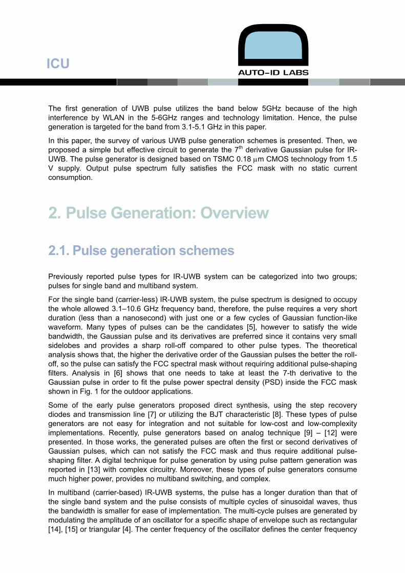
1. Introduction Ultra-wideband (UWB) is regulated for commercial use of the band from 3.1-10.6 GHz by Federal Communication Commission (FCC) with the constraints of spectral mask which determined the maximum average equivalent radiated isotropic power spectral density of –41.25dBm/MHz and a minimum bandwidth of 500 MHz [1]. According to FCC, the transmitted power should be under the mask shown in Fig. 1. There are two approaches for UWB applications, which are Multi-band OFDM UWB and Impulse-Radio UWB (IR-UWB). IR-UWB uses short-duration impulses modulated in time, polarity or amplitude. In MB-OFDM UWB, the UWB spectrum is divided into several subband with 528 MHz bandwidth and the carriers are modulated by applying the orthogonal frequency division multiplexing (OFDM). The latter is considered best suited for high data rate communication applications, whereas, IR-UWB for low-cost, low-power, low data rate wireless communication applications such as RF Tag [2], wireless sensor network [3], and wireless body area network (WBAN) [4].
Recently, low-cost, short-range wireless communication applications like radio frequency identification (RF-ID) and wireless sensor network have drawn much attention from the researcher as well as industries [3]. IR-UWB, without carrier signal, is one of the prominent candidates for those applications since circuit implementation is simpler, no up/down conversion or mixer is needed leading to substantial reduction in chip area and power consumption.
Fig. 1: FCC spectrum mask
IR-UWB uses the nano-second monocycle pulses to transmit the data signal over much wider frequency band than any conventional carrier based wireless systems. Thus, pulse generator circuit is an indispensable part in the IR-UWB transceivers. The generation of monocycle pulses, which can satisfy the FCC spectral mask with low power and low complexity, is still a challenge at present.
ICU
The first generation of UWB pulse utilizes the band below 5GHz because of the high interference by WLAN in the 5-6GHz ranges and technology limitation. Hence, the pulse generation is targeted for the band from 3.1-5.1 GHz in this paper.
In this paper, the survey of various UWB pulse generation schemes is presented. Then, we proposed a simple but effective circuit to generate the 7th derivative Gaussian pulse for IR-UWB. The pulse generator is designed based on TSMC 0.18 μm CMOS technology from 1.5 V supply. Output pulse spectrum fully satisfies the FCC mask with no static current consumption.
2. Pulse Generation: Overview
2.1. Pulse generation schemes
Previously reported pulse types for IR-UWB system can be categorized into two groups; pulses for single band and multiband system.
For the single band (carrier-less) IR-UWB system, the pulse spectrum is designed to occupy the whole allowed 3.1–10.6 GHz frequency band, therefore, the pulse requires a very short duration (less than a nanosecond) with just one or a few cycles of Gaussian function-like waveform. Many types of pulses can be the candidates [5], however to satisfy the wide bandwidth, the Gaussian pulse and its derivatives are preferred since it contains very small sidelobes and provides a sharp roll-off compared to other pulse types. The theoretical analysis shows that, the higher the derivative order of the Gaussian pulses the better the roll-off, so the pulse can satisfy the FCC spectral mask without requiring additional pulse-shaping filters. Analysis in [6] shows that one needs to take at least the 7-th derivative to the Gaussian pulse in order to fit the pulse power spectral density (PSD) inside the FCC mask shown in Fig. 1 for the outdoor applications.
Some of the early pulse generators proposed direct synthesis, using the step recovery diodes and transmission line [7] or utilizing the BJT characteristic [8]. These types of pulse generators are not easy for integration and not suitable for low-cost and low-complexity implementations. Recently, pulse generators based on analog technique [9] – [12] were presented. In those works, the generated pulses are often the first or second derivatives of Gaussian pulses, which can not satisfy the FCC mask and thus require additional pulse-shaping filter. A digital technique for pulse generation by using pulse pattern generation was reported in [13] with complex circuitry. Moreover, these types of pulse generators consume much higher power, provides no multiband switching, and complex.
In multiband (carrier-based) IR-UWB systems, the pulse has a longer duration than that of the single band system and the pulse consists of multiple cycles of sinusoidal waves, thus the bandwidth is smaller for ease of implementation. The multi-cycle pulses are generated by modulating the amplitude of an oscillator for a specific shape of envelope such as rectangular [14], [15] or triangular [4]. The center frequency of the oscillator defines the center frequency
ICU
of the pulse spectrum which should be tunable for the sub-band switching. Depending on the shape of the pulse envelope, the pulse spectrum shows different characteristics. According to [16], the triangular-enveloped pulse can provide highest sidelobe suppression of 26 dB, while only 13 dB can be obtained with rectangular envelope. The amount of sidelobe suppression factor is important for the multiband system in order to avoid the adjacent channel interferences. For the best performance, the shape of the pulse should be symmetric in time domain, so that its spectrum is concentrated symmetrically around the center frequency with largest amount of equal sidelobe suppression.
In [4], a pulse is created by multiplying a triangular envelope with a local oscillator (LO) output. This approach provides a sidelobe suppression of around 20 dB. However, the complexity, a number of functional blocks including a Phase-Lock Loop (PLL), makes it less attractive due to the large chip size and high DC current consumption. Another way to generate the multiband pulse is to gate an oscillator as proposed in [14]. The problem with this technique is that the envelope of the output pulse is a square shape. Therefore, an additional filtering is required for the sidelobe rejection. It is also power consuming due to the LO operation at the center frequency of pulse spectrum.
2.2. Pulse Type Selection
The selection of monocycle pulse types is the primary consideration when designing pulse generator, because the impulse type will determine the spectral characteristics, system modulation and performance. Gaussian derivative pulse is the most commonly used and preferred in IR-UWB systems since it has wide bandwidth, no DC component and no side lobes in its spectrum. As mentioned above, however, the low order Gaussian’s derivative pulse is hard to meet the FCC mask. Theory analysis in [6] shows that, when the derivative orders get higher, the better roll-off the pulse has, also the center frequency is shifted to higher frequencies and low power spectrum distributed in low frequencies. Because of this reason, to satisfy FCC mask, the order of derivative should be increased.
For indoor application, 5th order derivative of Gaussian pulse can meet the FCC spectral mask. Fig. 1 shows that the FCC spectral mask for outdoor applications is 10dB more stringent than the indoor one. Therefore, the pulses for outdoor application requires a higher order of derivatives. However, when the order of derivative increases, hardware becomes more complicated. From [6], 7th derivative Gaussian pulse is the most effective and suitable pulse for IR-UWB outdoor applications. Its spectrum complies with FCC mask for outdoor applications without filtering or frequency shifting.
ICU
3. Pulse Generator Circuit Design
3.1. Block Diagram
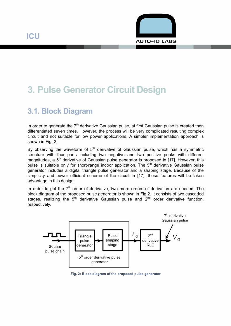
In order to generate the 7th derivative Gaussian pulse, at first Gaussian pulse is created then differentiated seven times. However, the process will be very complicated resulting complex circuit and not suitable for low power applications. A simpler implementation approach is shown in Fig. 2.
By observing the waveform of 5th derivative of Gaussian pulse, which has a symmetric structure with four parts including two negative and two positive peaks with different magnitudes, a 5th derivative of Gaussian pulse generator is proposed in [17]. However, this pulse is suitable only for short-range indoor application. The 5th derivative Gaussian pulse generator includes a digital triangle pulse generator and a shaping stage. Because of the simplicity and power efficient scheme of the circuit in [17], these features will be taken advantage in this design.
In order to get the 7th order of derivative, two more orders of derivation are needed. The block diagram of the proposed pulse generator is shown in Fig.2. It consists of two cascaded stages, realizing the 5th derivative Gaussian pulse and 2nd order derivative function, respectively.
5th order derivative pulse generator
2nd derivative
RLC
Triangle pulse
generator
Pulse shaping stageSquare
pulse chain
7th derivative Gaussian pulse
i o Vo
Fig. 2: Block diagram of the proposed pulse generator
ICU
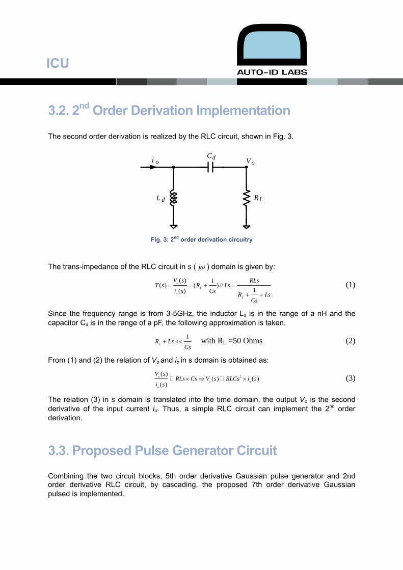
3.2. 2nd Order Derivation Implementation
The second order derivation is realized by the RLC circuit, shown in Fig. 3.
L d
Cd
RL
i o V o
Fig. 3: 2nd order derivation circuitry
The trans-impedance of the RLC circuit in s ( jω ) domain is given by:
( ) 1( ) ( ) //
1( )o
L
oL
V s RLsT s R Ls
i s Cs R LsCs
= = + =
+ +
(1)
Since the frequency range is from 3-5GHz, the inductor Ld is in the range of a nH and the capacitor Cd is in the range of a pF, the following approximation is taken.
1LR Ls
Cs+ << with RL =50 Ohms (2)
From (1) and (2) the relation of Vo and io in s domain is obtained as:
2( )( ) ( )
( )o
o
o
V soRLs Cs V s RLCs i s
i s× ⇒ × (3)
The relation (3) in s domain is translated into the time domain, the output Vo is the second derivative of the input current io. Thus, a simple RLC circuit can implement the 2nd order derivation.
3.3. Proposed Pulse Generator Circuit Combining the two circuit blocks, 5th order derivative Gaussian pulse generator and 2nd order derivative RLC circuit, by cascading, the proposed 7th order derivative Gaussian pulsed is implemented.
ICU
M2
M1
M4
M3
Co
L d
Cd
RL
io V o
A
B
C
D
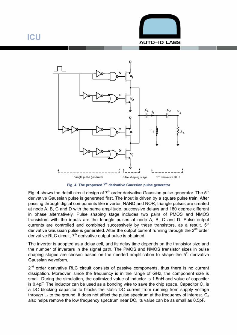
Triangle pulse generator 2nd derivative RLCPulse shaping stage Fig. 4: The proposed 7th derivative Gaussian pulse generator
Fig. 4 shows the detail circuit design of 7th order derivative Gaussian pulse generator. The 5th derivative Gaussian pulse is generated first. The input is driven by a square pulse train. After passing through digital components like inverter, NAND and NOR, triangle pulses are created at node A, B, C and D with the same amplitude, successive delays and 180 degree different in phase alternatively. Pulse shaping stage includes two pairs of PMOS and NMOS transistors with the inputs are the triangle pulses at node A, B, C and D. Pulse output currents are controlled and combined successively by these transistors, as a result, 5th derivative Gaussian pulse is generated. After the output current running through the 2nd order derivative RLC circuit, 7th derivative output pulse is obtained.
The inverter is adopted as a delay cell, and its delay time depends on the transistor size and the number of inverters in the signal path. The PMOS and NMOS transistor sizes in pulse shaping stages are chosen based on the needed amplification to shape the 5th derivative Gaussian waveform.
2nd order derivative RLC circuit consists of passive components, thus there is no current dissipation. Moreover, since the frequency is in the range of GHz, the component size is small. During the simulation, the optimized value of inductor is 1.5nH and value of capacitor is 0.4pF. The inductor can be used as a bonding wire to save the chip space. Capacitor Co is a DC blocking capacitor to blocks the static DC current from running from supply voltage through Ld to the ground. It does not affect the pulse spectrum at the frequency of interest. Co also helps remove the low frequency spectrum near DC, its value can be as small as 0.5pF.
ICU
4. Simulation Results And Discussion The proposed pulse generator is designed using TSMC 0.18 μm CMOS technology with 1.5 V supply.
4.1. Output Pulse Train
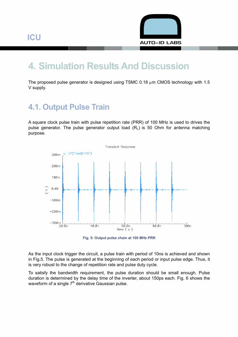
A square clock pulse train with pulse repetition rate (PRR) of 100 MHz is used to drives the pulse generator. The pulse generator output load (RL) is 50 Ohm for antenna matching purpose.
Fig. 5: Output pulse chain at 100 MHz PRR
As the input clock trigger the circuit, a pulse train with period of 10ns is achieved and shown in Fig.5. The pulse is generated at the beginning of each period or input pulse edge. Thus, it is very robust to the change of repetition rate and pulse duty cycle.
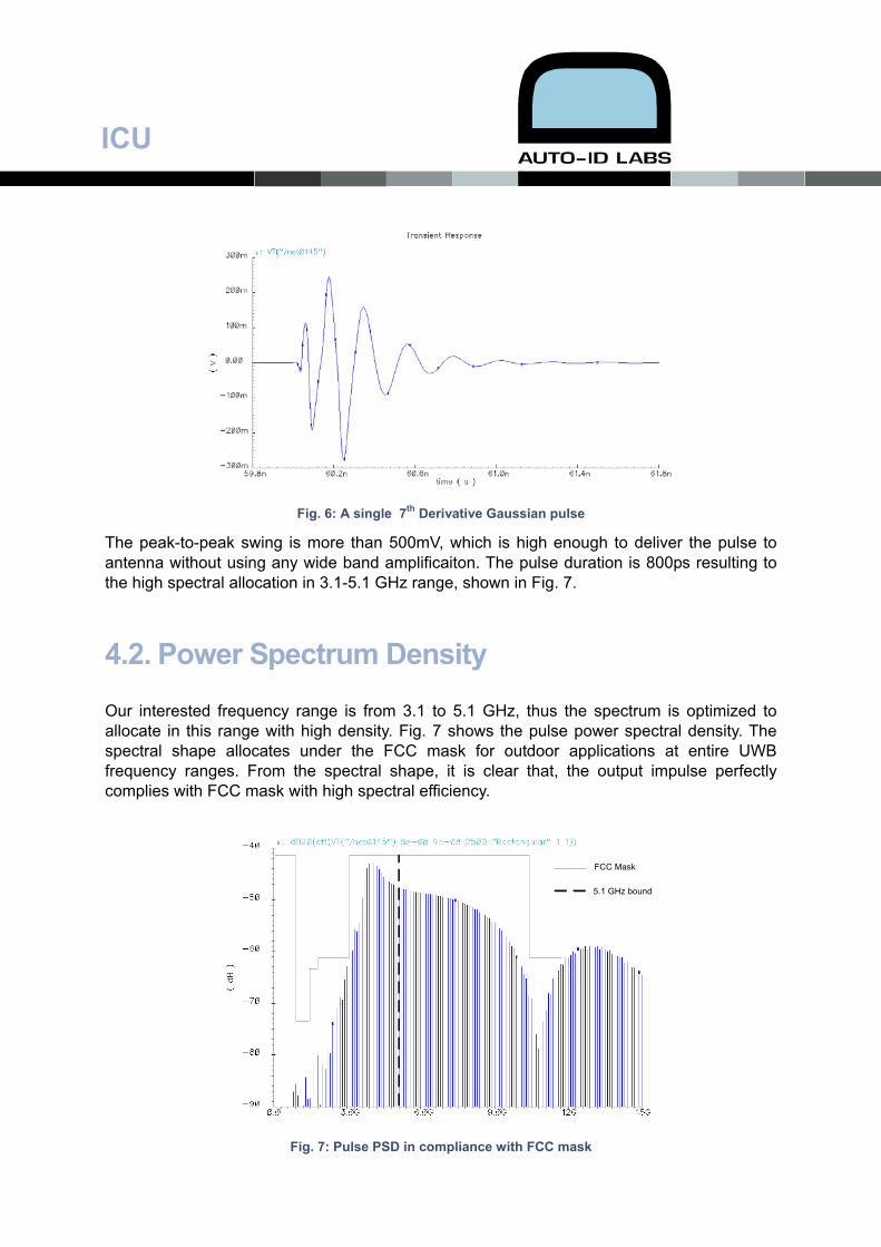
To satisfy the bandwidth requirement, the pulse duration should be small enough. Pulse duration is determined by the delay time of the inverter, about 150ps each. Fig. 6 shows the waveform of a single 7th derivative Gaussian pulse.
ICU
Fig. 6: A single 7th Derivative Gaussian pulse
The peak-to-peak swing is more than 500mV, which is high enough to deliver the pulse to antenna without using any wide band amplificaiton. The pulse duration is 800ps resulting to the high spectral allocation in 3.1-5.1 GHz range, shown in Fig. 7.
4.2. Power Spectrum Density
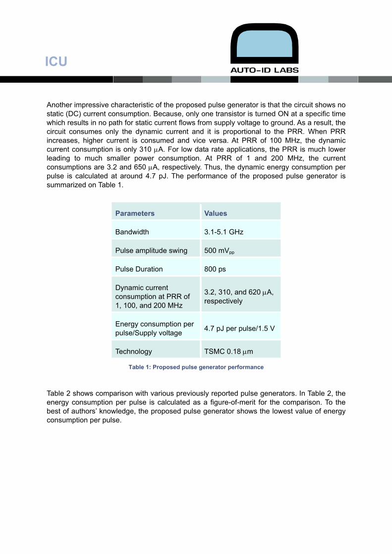
Our interested frequency range is from 3.1 to 5.1 GHz, thus the spectrum is optimized to allocate in this range with high density. Fig. 7 shows the pulse power spectral density. The spectral shape allocates under the FCC mask for outdoor applications at entire UWB frequency ranges. From the spectral shape, it is clear that, the output impulse perfectly complies with FCC mask with high spectral efficiency.
FCC Mask
5.1 GHz bound
Fig. 7: Pulse PSD in compliance with FCC mask
ICU
Another impressive characteristic of the proposed pulse generator is that the circuit shows no static (DC) current consumption. Because, only one transistor is turned ON at a specific time which results in no path for static current flows from supply voltage to ground. As a result, the circuit consumes only the dynamic current and it is proportional to the PRR. When PRR increases, higher current is consumed and vice versa. At PRR of 100 MHz, the dynamic current consumption is only 310 μA. For low data rate applications, the PRR is much lower leading to much smaller power consumption. At PRR of 1 and 200 MHz, the current consumptions are 3.2 and 650 μA, respectively. Thus, the dynamic energy consumption per pulse is calculated at around 4.7 pJ. The performance of the proposed pulse generator is summarized on Table 1.
Parameters Values
Bandwidth 3.1-5.1 GHz
Pulse amplitude swing 500 mVpp
Pulse Duration 800 ps
Dynamic current consumption at PRR of 1, 100, and 200 MHz
3.2, 310, and 620 μA, respectively
Energy consumption per pulse/Supply voltage 4.7 pJ per pulse/1.5 V
Technology TSMC 0.18 μm
Table 1: Proposed pulse generator performance
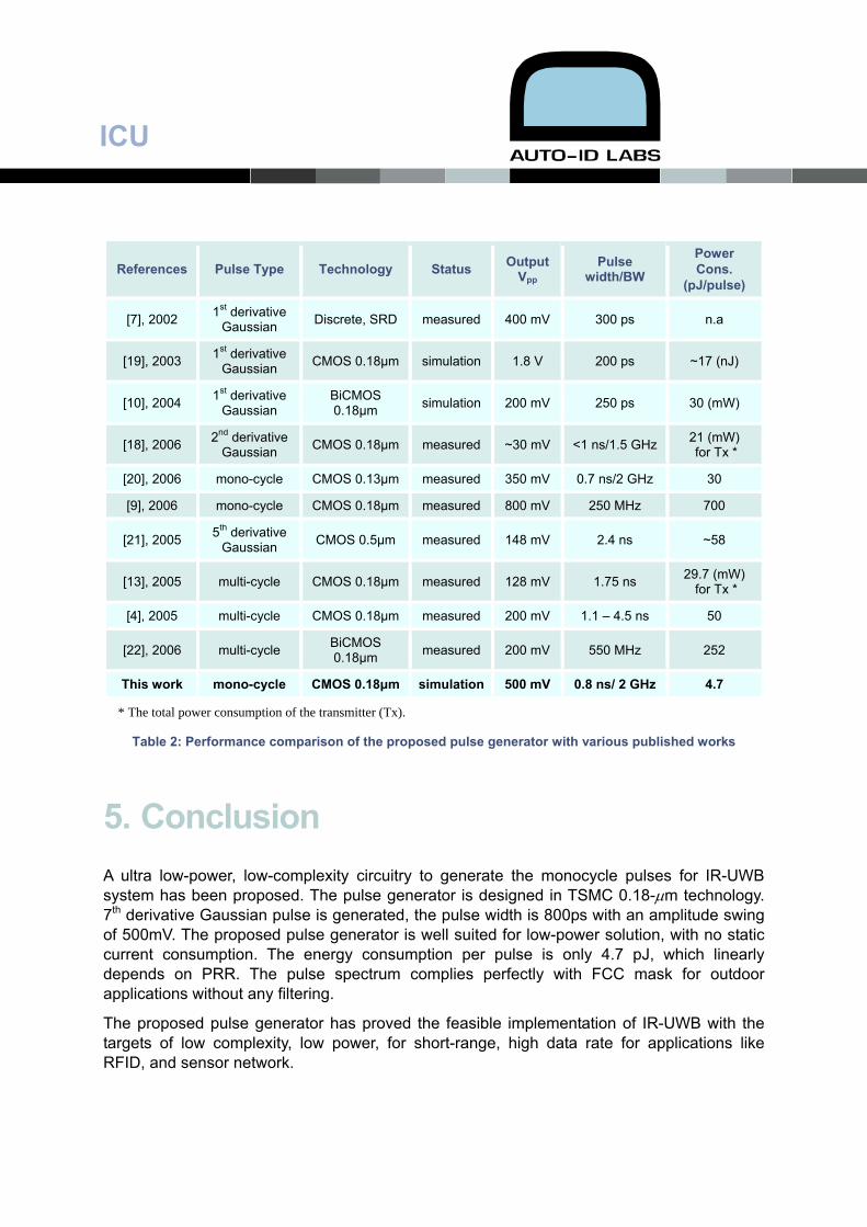
Table 2 shows comparison with various previously reported pulse generators. In Table 2, the energy consumption per pulse is calculated as a figure-of-merit for the comparison. To the best of authors’ knowledge, the proposed pulse generator shows the lowest value of energy consumption per pulse.
ICU
References Pulse Type Technology Status Output Vpp
Pulse width/BW
Power Cons.
(pJ/pulse)
[7], 2002 1st derivative Gaussian Discrete, SRD measured 400 mV 300 ps n.a
[19], 2003 1st derivative Gaussian CMOS 0.18μm simulation 1.8 V 200 ps ~17 (nJ)
[10], 2004 1st derivative Gaussian
BiCMOS 0.18μm simulation 200 mV 250 ps 30 (mW)
[18], 2006 2nd derivative Gaussian CMOS 0.18μm measured ~30 mV <1 ns/1.5 GHz 21 (mW)
for Tx *
[20], 2006 mono-cycle CMOS 0.13μm measured 350 mV 0.7 ns/2 GHz 30
[9], 2006 mono-cycle CMOS 0.18μm measured 800 mV 250 MHz 700
[21], 2005 5th derivative Gaussian CMOS 0.5μm measured 148 mV 2.4 ns ~58
[13], 2005 multi-cycle CMOS 0.18μm measured 128 mV 1.75 ns 29.7 (mW) for Tx *
[4], 2005 multi-cycle CMOS 0.18μm measured 200 mV 1.1 – 4.5 ns 50
[22], 2006 multi-cycle BiCMOS 0.18μm measured 200 mV 550 MHz 252
This work mono-cycle CMOS 0.18μm simulation 500 mV 0.8 ns/ 2 GHz 4.7
* The total power consumption of the transmitter (Tx).
Table 2: Performance comparison of the proposed pulse generator with various published works
5. Conclusion A ultra low-power, low-complexity circuitry to generate the monocycle pulses for IR-UWB system has been proposed. The pulse generator is designed in TSMC 0.18-μm technology. 7th derivative Gaussian pulse is generated, the pulse width is 800ps with an amplitude swing of 500mV. The proposed pulse generator is well suited for low-power solution, with no static current consumption. The energy consumption per pulse is only 4.7 pJ, which linearly depends on PRR. The pulse spectrum complies perfectly with FCC mask for outdoor applications without any filtering.
The proposed pulse generator has proved the feasible implementation of IR-UWB with the targets of low complexity, low power, for short-range, high data rate for applications like RFID, and sensor network.
ICU
References: [1] Federal Communications Commission, ” Revision of part 15 of the commission’s rules
regarding ultra-wideband transmission systems: First report and order,” Washington DC, ET-docket 98-153, FCC 02-48, pp. 1–118, Febuary 14, 2002.
[2] L. Stoica, S .Tiuraniemi, A. Rabbachin, and I. Oppermann, “An ultra wideband Tag circuit transceiver architecture,” in Proc. Joint Ultra-Wideband Syst. Technol. Conf., Japan, May 2004, pp. 258-262.
[3] I. Oppermann, L. Stoica, A. Rabachin, Z. Shelby, and J. Haapola, “UWB wireless sensor networks: UWEN - a practical example,” IEEE Commun. Mag., vol. 42, pp. S27-S32, Dec. 2004.
[4] J. Ryckaert, C. Desset, A. Fort, M. Badaroglu, V. De Heyn, P. Wambacq, G. Van der Plas, S. Donnay, B. Van Poucke, and B. Gyselinckx, “Ultra-Wideband transmitter for low-power Wireless Body Area Networks design and evaluation,” IEEE Trans.Circuits Syst.-Part I, vol. 52, no. 12, pp. 2515–2525, Dec. 2005.
[5] X. Chen and S. Kiaei, “Monocycle shapes for ultra wideband system”, IEEE Int. Symp. Circuits And Syslems (ISCAS), May 2002, vol.1, pp. 597–600.
[6] H. Sheng, P. Orlik, A.M. Haimovich, L.J. Cimini, and J. Zhang, “On the spectral and power requirements for ultra-wideband transmission,” IEEE Int. Conf. Communications (ICC), May 2003, vol.1, pp. 738–742.
[7] J. Han and C. Nguyen, “A new ultra-wideband, ultra-short monocycle pulse generator with reduced ringing,” IEEE Micro. Wireles. Compon. Lett., vol. 12, no. 6, pp. 206–208, Jun. 2002.
[8] J.F.M. Gerrits, and J.R. Farserotu, “Wavelet generation circuit for UWB impulse radio applications,” Electron. Lett., vol. 38, no. 25, pp. 1737–1738, Dec. 2002.
[9] T. Terada, S. Yoshizumi, M. Muqsith, Y. Sanada, and T. Kuroda, “A CMOS Ultra-wideband impulse radio transceiver for 1-Mb/s data communications and ±2.5-cm rang finding,” IEEE J.Solid-State Cicuits, vol. 41, no. 4, pp. 891–898, April 2006.
[10] S. Bagga, W.A Serdijin, and J.R. Long, “A PPM Gaussian monocycle transmitter for ultra-wideband communications,” in Proc. Joint Ultra Wideband Syst. Technol. Conf., Japan, May 2004, pp. 130–134.
[11] Y. Jeong, S. Jung, and J. Liu, “A CMOS impulse generator for UWB wireless communication systems,” IEEE Int. Symp. Circuits and Systems (ISCAS), , May 2004, vol. 4, pp. 129–132.
[12] B. Jung, Y.-H. Tseng, J. Harvey, and R. Harjani, “Pulse generator design for UWB IR communication systems,” IEEE Int. Symp. Circuits and Systems (ISCAS), 23–26 May 2005, pp. 4381– 4384.
[13] T. Norimatsu, R. Fujiwara, M. Kokubo, M. Miyazaki, Y. Ookuma, M. Hayakawa, S. Kobayashi, N. Koshizuka, and K. Sakamura, “A novel UWB impulse-radio transmitter with
ICU
all-digitally controlled pulse generator,” IEEE Proc. 31st European Solid-State Circuits Conf. (ESSCIRC), Sept. 2005, pp. 267–270.
[14] Y.H. Choi, “Gated uwb pulse signal generation,” IEEE Joint Int. Workshop of UWBST and IWUWBS, May 2004, pp. 122–124.
[15] Azakkour. A, Regis. M, Pourchet. F, and Alquie. G, “A new integrated monocycle generator and transmitter for ultra-wideband (UWB) communications,” IEEE Radio Freq. Integr. Circuits Symp. Dig.(RFIC) Symposium, June 2005, pp. 79–82.
[16] J. Ryckaert, M. Badaroglu, C. Desset, V. De Heyn, G. ven der Plas, P. Wambacq, B. van Poucke, and S. Donnay, “Carrier-based UWB impulse radio simplicity flexibility and pulser implementation in 0.18-micron CMOS,” IEEE Int Conf. Ultra Wideband, , Sept. 2005, pp. 432–437.
[17] Hyunseok Kim and Youngjoong Joo,” Fifth-derivative Gaussian pulse generator for UWB system,” IEEE Radio Frequency integrated Circuits (RFIC) Symposium, pp.671- 674, 12-14 June 2005.
[18] Y. Zheng, Y. Zhang, and Y. Tong, “A novel wireless interconnect technology using impluse radio for interchip communications,” IEEE Trans. Micro. Theory Tech., vol. 54, no. 4, part II, pp. 1912–1920, April 2006.
[19] K. Marsden, H.-J. Lee, Dong Ha; and H.-S. Lee, “Low power CMOS re-programmable pulse generator for UWB systems,” in Proc. IEEE Ultra Wideband Syst. Technol. Conf., Nov. 2003, pp. 443–447.
[20] L. Smaini, C. Tinella, D. Helal, C. Stoecklin, L. Chabert, C. Devaucelle, R. Cattenoz, and D. Belot, “Single-chip CMOS pulse generator for UWB systems,” in IEEE Proc. 31st European Solid-State Circuits Conf. (ESSCIRC), Sept. 2005, pp. 271–274.
[21] H. Kim, and Y. Joo, “Fifth-derivative Gaussian pulse generator for UWB system,” in IEEE Radio Freq. Integr. Circuits Symp. Dig. (RFIC), Jun. 2005, pp. 671–674.
[22] D.D. Wentzloff and A.P. Chandrakasan, “Gaussian pulse generators for subbanded Ultra-Wideband transmitters,” IEEE Trans. Micro. Theory Tech., vol. 54, no. 4, part II, pp. 1647–1655, April 2006.