4/3-way servo solenoid directional - kanflu.com · a0 b AB P T 2/18 Bosch Rexroth AG Hydraulics...
20
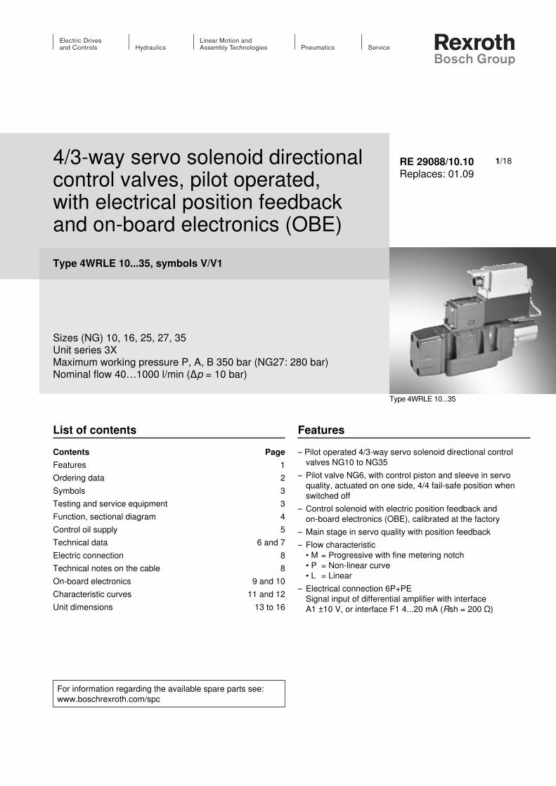
1/18 4/3-way servo solenoid directional control valves, pilot operated, with electrical position feedback and on-board electronics (OBE) Type 4WRLE 10...35, symbols V/V1 Sizes (NG) 10, 16, 25, 27, 35 Unit series 3X Maximum working pressure P, A, B 350 bar (NG27: 280 bar) Nominal flow 40…1000 l/min (Δp = 10 bar) RE 29088/10.10 Replaces: 01.09 List of contents Contents Page Features 1 Ordering data 2 Symbols 3 Testing and service equipment 3 Function, sectional diagram 4 Control oil supply 5 Technical data 6 and 7 Electric connection 8 Technical notes on the cable 8 On-board electronics 9 and 10 Characteristic curves 11 and 12 Unit dimensions 13 to 16 Features – Pilot operated 4/3-way servo solenoid directional control valves NG10 to NG35 – Pilot valve NG6, with control piston and sleeve in servo quality, actuated on one side, 4/4 fail-safe position when switched off – Control solenoid with electric position feedback and on-board electronics (OBE), calibrated at the factory – Main stage in servo quality with position feedback – Flow characteristic • M = Progressive with fine metering notch • P = Non-linear curve • L = Linear – Electrical connection 6P+PE Signal input of differential amplifier with interface A1 ±10 V, or interface F1 4...20 mA (Rsh = 200 Ω) For information regarding the available spare parts see: www.boschrexroth.com/spc Type 4WRLE 10...35
-
Upload
nguyenkhanh -
Category
Documents
-
view
224 -
download
1
Transcript of 4/3-way servo solenoid directional - kanflu.com · a0 b AB P T 2/18 Bosch Rexroth AG Hydraulics...
1/184/3-way servo solenoid directional control valves, pilot operated,with electrical position feedback and on-board electronics (OBE)Type 4WRLE 10...35, symbols V/V1
Sizes (NG) 10, 16, 25, 27, 35Unit series 3XMaximum working pressure P, A, B 350 bar (NG27: 280 bar)Nominal flow 40…1000 l/min (Δp = 10 bar)
RE 29088/10.10Replaces: 01.09
List of contentsContents PageFeatures 1Ordering data 2Symbols 3Testing and service equipment 3Function, sectional diagram 4Control oil supply 5Technical data 6 and 7Electric connection 8Technical notes on the cable 8On-board electronics 9 and 10Characteristic curves 11 and 12Unit dimensions 13 to 16
Features – Pilot operated 4/3-way servo solenoid directional control
valves NG10 to NG35– Pilot valve NG6, with control piston and sleeve in servo
quality, actuated on one side, 4/4 fail-safe position when switched off
– Control solenoid with electric position feedback and on-board electronics (OBE), calibrated at the factory
– Main stage in servo quality with position feedback– Flow characteristic
• M = Progressive with fine metering notch• P = Non-linear curve• L = Linear
– Electrical connection 6P+PESignal input of differential amplifier with interfaceA1 ±10 V, or interface F1 4...20 mA (Rsh = 200 Ω)
For information regarding the available spare parts see:www.boschrexroth.com/spc
Type 4WRLE 10...35
a 0 b
A B
P T
2/18 Bosch Rexroth AG Hydraulics 4WRLE 10...35 RE 29088/10.10
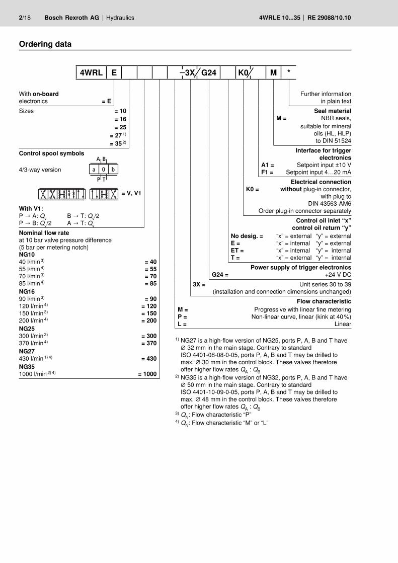
Ordering data
With on-board electronics = ESizes = 10 = 16 = 25 = 27 1) = 35 2)
Control spool symbols
4/3-way version
= V, V1
With V1:P → A: Qv B → T: Qv/2P → B: Qv/2 A → T: Qv
Nominal flow rate at 10 bar valve pressure difference(5 bar per metering notch)NG1040 l/min 3) = 4055 l/min 4) = 5570 l/min 3) = 7085 l/min 4) = 85NG1690 l/min 3) = 90120 l/min 4) = 120150 l/min 3) = 150200 l/min 4) = 200NG25300 l/min 3) = 300370 l/min 4) = 370NG27430 l/min 1) 4) = 430 NG351000 l/min 2) 4) = 1000
Further information in plain text
Seal materialM = NBR seals,
suitable for mineraloils (HL, HLP) to DIN 51524
Interface for trigger electronics
A1 = Setpoint input ±10 V F1 = Setpoint input 4…20 mA
Electrical connectionK0 = without plug-in connector,
with plug toDIN 43563-AM6
Order plug-in connector separatelyControl oil inlet “x”
control oil return “y”No desig. = “x” = external “y” = externalE = “x” = internal “y” = externalET = “x” = internal “y” = internalT = “x” = external “y” = internal
Power supply of trigger electronics G24 = +24 V DC
3X = Unit series 30 to 39(installation and connection dimensions unchanged)
Flow characteristicM = Progressive with linear fine meteringP = Non-linear curve, linear (kink at 40 %)L = Linear
1) NG27 is a high-flow version of NG25, ports P, A, B and T have ∅ 32 mm in the main stage. Contrary to standard ISO 4401-08-08-0-05, ports P, A, B and T may be drilled to max. ∅ 30 mm in the control block. These valves therefore offer higher flow rates QA : QB
2) NG35 is a high-flow version of NG32, ports P, A, B and T have ∅ 50 mm in the main stage. Contrary to standard ISO 4401-10-09-0-05, ports P, A, B and T may be drilled to max. ∅ 48 mm in the control block. These valves therefore offer higher flow rates QA : QB
3) QN: Flow characteristic “P”4) QN: Flow characteristic “M” or “L”
4WRL E 3X G24 K0 M *
Hydraulics Bosch Rexroth AGRE 29088/10.10 4WRLE 10...35 3/18
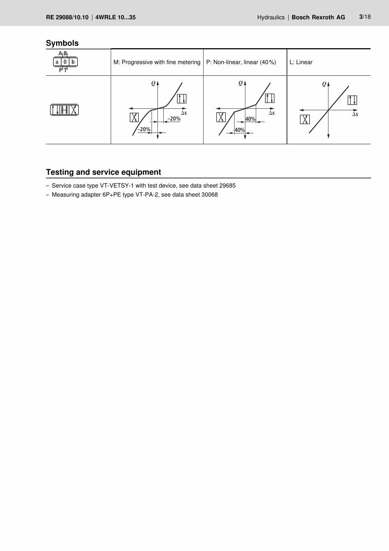
Symbols
a 0 bA B
P TM: Progressive with fine metering P: Non-linear, linear (40 %) L: Linear
20%
20%
Ds
Q
40%
40%Ds
Q
Ds
Q
Testing and service equipment– Service case type VT-VETSY-1 with test device, see data sheet 29685– Measuring adapter 6P+PE type VT-PA-2, see data sheet 30068
1
T
A P B
X Y
2
3
4/18 Bosch Rexroth AG Hydraulics 4WRLE 10...35 RE 29088/10.10
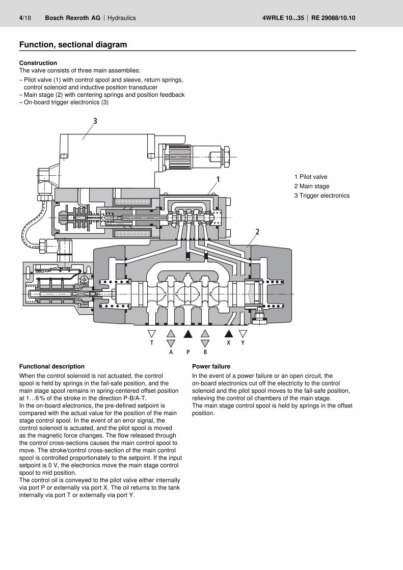
Function, sectional diagram
ConstructionThe valve consists of three main assemblies:– Pilot valve (1) with control spool and sleeve, return springs,
control solenoid and inductive position transducer– Main stage (2) with centering springs and position feedback– On-board trigger electronics (3)
Power failureIn the event of a power failure or an open circuit, the on-board electronics cut off the electricity to the control solenoid and the pilot spool moves to the fail-safe position, relieving the control oil chambers of the main stage. The main stage control spool is held by springs in the offset position.
Functional descriptionWhen the control solenoid is not actuated, the control spool is held by springs in the fail-safe position, and the main stage spool remains in spring-centered offset position at 1…6 % of the stroke in the direction P-B/A-T.In the on-board electronics, the pre-defined setpoint is compared with the actual value for the position of the main stage control spool. In the event of an error signal, the control solenoid is actuated, and the pilot spool is moved as the magnetic force changes. The flow released through the control cross-sections causes the main control spool to move. The stroke/control cross-section of the main control spool is controlled proportionately to the setpoint. If the input setpoint is 0 V, the electronics move the main stage control spool to mid position. The control oil is conveyed to the pilot valve either internally via port P or externally via port X. The oil returns to the tank internally via port T or externally via port Y.
1 Pilot valve2 Main stage3 Trigger electronics
X Y
Pv Tv
P T
Y X
PvTv
P
A B
P T
A B
P T
A B
P T
A B
P TT
Y X
X
Y
G G
b
G
b
G
b
G G
b
a
a
a
a
G
G
P T
TP
A
A
B
B
Ta b
P
A B
0a b
G
G
XP Y T
Hydraulics Bosch Rexroth AGRE 29088/10.10 4WRLE 10...35 5/18
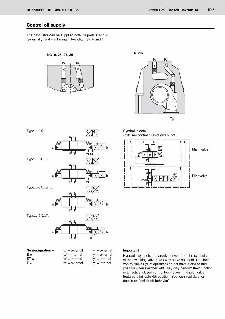
Control oil supply
ImportantHydraulic symbols are largely derived from the symbols of the switching valves. 4/3-way servo solenoid directional control valves (pilot operated) do not have a closed mid position when switched off! They only perform their function in an active, closed control loop, even if the pilot valve features a fail-safe 4th position. See technical data for details on “switch-off behavior”.
NG10, 25, 27, 35 NG16
Type...–3X...
Type...–3X...E...
Type...–3X...ET...
Type...–3X...T...
No designation = “x” = external “y” = externalE = “x” = internal “y” = externalET = “x” = internal “y” = internalT = “x” = external “y” = internal
The pilot valve can be supplied both via ports X and Y (externally) and via the main flow channels P and T.
Symbol in detail(external control oil inlet and outlet)
Main valve
Pilot valve
6/18 Bosch Rexroth AG Hydraulics 4WRLE 10...35 RE 29088/10.10
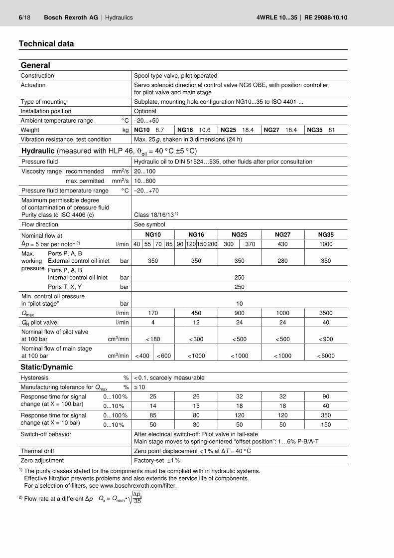
Technical data
GeneralConstruction Spool type valve, pilot operatedActuation Servo solenoid directional control valve NG6 OBE, with position controller
for pilot valve and main stageType of mounting Subplate, mounting hole configuration NG10...35 to ISO 4401-...Installation position OptionalAmbient temperature range °C –20...+50Weight kg NG10 8.7 NG16 10.6 NG25 18.4 NG27 18.4 NG35 81Vibration resistance, test condition Max. 25 g, shaken in 3 dimensions (24 h)
Static/DynamicHysteresis % < 0.1, scarcely measurableManufacturing tolerance for Qmax % ≦ 10Response time for signal change (at X = 100 bar)
0...100 % 25 26 32 32 900...10 % 14 15 18 18 40
Response time for signal change (at X = 10 bar)
0...100 % 85 80 120 120 3500...10 % 50 30 50 50 150
Switch-off behavior After electrical switch-off: Pilot valve in fail-safeMain stage moves to spring-centered “offset position”: 1…6% P-B/A-T
Thermal drift Zero point displacement < 1 % at ΔT = 40 °CZero adjustment Factory-set ±1 %
1) The purity classes stated for the components must be complied with in hydraulic systems. Effective filtration prevents problems and also extends the service life of components. For a selection of filters, see www.boschrexroth.com/filter.
2) Flow rate at a different Δp Qx = Qnom • Δpx35
Hydraulic (measured with HLP 46, oil = 40 °C ±5 °C)Pressure fluid Hydraulic oil to DIN 51524…535, other fluids after prior consultationViscosity range recommended mm2/s 20...100
max. permitted mm2/s 10...800Pressure fluid temperature range °C –20...+70Maximum permissible degree of contamination of pressure fluidPurity class to ISO 4406 (c) Class 18/16/13 1)
Flow direction See symbol
Nominal flow at Δp = 5 bar per notch 2) l/min
NG10 NG16 NG25 NG27 NG3540 55 70 85 90 120 150 200 300 370 430 1000
Max. working pres sure
Ports P, A, BExternal control oil inlet bar 350 350 350 280 350Ports P, A, BInternal control oil inlet bar 250Ports T, X, Y bar 250
Min. control oil pressure in “pilot stage” bar 10Qmax l/min 170 450 900 1000 3500QN pilot valve l/min 4 12 24 24 40Nominal flow of pilot valve at 100 bar cm3/min < 180 < 300 < 500 < 500 < 900Nominal flow of main stage at 100 bar cm3/min < 400 < 600 < 1000 < 1000 < 1000 < 6000
Volt tomA
Logic1 or 2Stage
P-B
4...12...20 mA
4...20 mA4...20 mA
P-A
Stroke
II sign.
Stroke
II sign.
NG6/10
Mainstage
24 V =
10 V
–10 V… 0… +10 V
LVDT Sign.
Logic1 or 2Stage
P-B
P-A
Stroke
II sign.
Stroke
II sign.
NG6/10
Mainstage
24 V =0... 10 V0... 10 V
10 V 10 V
Hydraulics Bosch Rexroth AGRE 29088/10.10 4WRLE 10...35 7/18
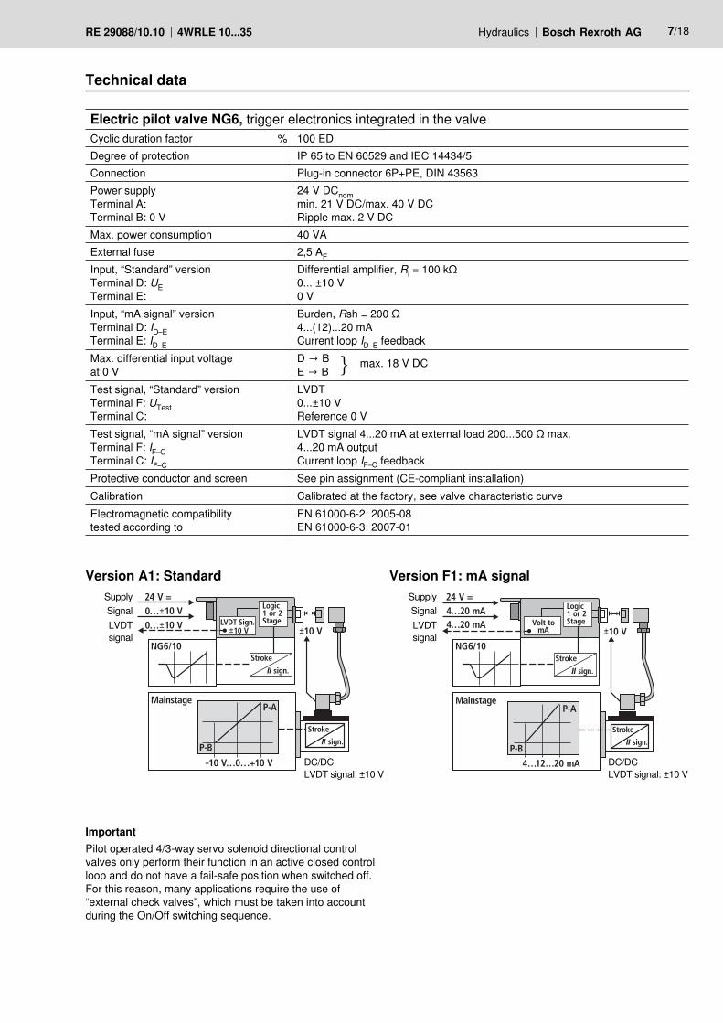
Technical data
Electric pilot valve NG6, trigger electronics integrated in the valveCyclic duration factor % 100 EDDegree of protection IP 65 to EN 60529 and IEC 14434/5Connection Plug-in connector 6P+PE, DIN 43563Power supplyTerminal A:Terminal B: 0 V
24 V DCnommin. 21 V DC/max. 40 V DCRipple max. 2 V DC
Max. power consumption 40 VAExternal fuse 2,5 AF
Input, “Standard” versionTerminal D: UETerminal E:
Differential amplifier, Ri = 100 kΩ0... ±10 V0 V
Input, “mA signal” versionTerminal D: ID–ETerminal E: ID–E
Burden, Rsh = 200 Ω4...(12)...20 mACurrent loop ID–E feedback
Max. differential input voltage at 0 V
D → BE → B
max. 18 V DC
Test signal, “Standard” versionTerminal F: UTestTerminal C:
LVDT0...±10 VReference 0 V
Test signal, “mA signal” versionTerminal F: IF–CTerminal C: IF–C
LVDT signal 4...20 mA at external load 200...500 Ω max.4...20 mA outputCurrent loop IF–C feedback
Protective conductor and screen See pin assignment (CE-compliant installation)Calibration Calibrated at the factory, see valve characteristic curveElectromagnetic compatibilitytested according to
EN 61000-6-2: 2005-08EN 61000-6-3: 2007-01
Version A1: Standard Version F1: mA signal
ImportantPilot operated 4/3-way servo solenoid directional control valves only perform their function in an active closed control loop and do not have a fail-safe position when switched off. For this reason, many applications require the use of “external check valves”, which must be taken into account during the On/Off switching sequence.
SignalSignalSupplySupply
LVDTsignal
LVDTsignal
DC/DC LVDT signal: ±10 V
DC/DC LVDT signal: ±10 V
1
24 V=
3
4
5
A P B T
62
8/18 Bosch Rexroth AG Hydraulics 4WRLE 10...35 RE 29088/10.10
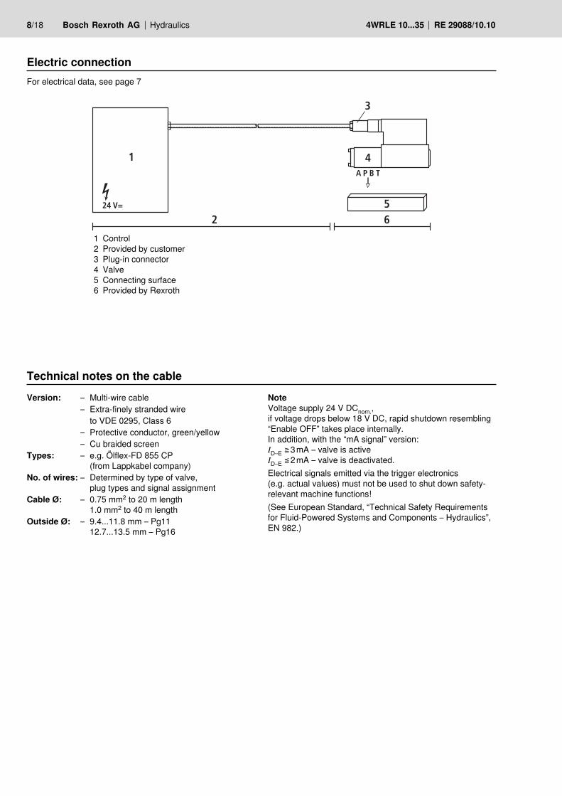
Electric connectionFor electrical data, see page 7
1 Control2 Provided by customer3 Plug-in connector4 Valve5 Connecting surface6 Provided by Rexroth
Technical notes on the cableVersion: – Multi-wire cable Note
Voltage supply 24 V DCnom.,if voltage drops below 18 V DC, rapid shutdown resembling“Enable OFF” takes place internally.In addition, with the “mA signal” version:ID–E ≧ 3 mA – valve is activeID–E ≦ 2 mA – valve is deactivated.Electrical signals emitted via the trigger electronics (e.g. actual values) must not be used to shut down safety-relevant machine functions!(See European Standard, “Technical Safety Requirements for Fluid-Powered Systems and Components – Hydraulics”, EN 982.)
– Extra-finely stranded wire to VDE 0295, Class 6
– Protective conductor, green/yellow– Cu braided screen
Types: – e.g. Ölflex-FD 855 CP(from Lappkabel company)
No. of wires: – Determined by type of valve, plug types and signal assignment
Cable Ø: – 0.75 mm2 to 20 m length1.0 mm2 to 40 m length
Outside Ø: – 9.4...11.8 mm – Pg1112.7...13.5 mm – Pg16
ABC
F
+24 V=
0 V
10k
100k100k
DC
DC
PID+–PD
+–
1 –15 V=
2 ref. 0
3 +15 V=
4
DE UD–E
2.5 AF
+UB
+UB
+15 V– 15 V
0… 10 V+–
0… 10 V+–
0… 10 V+–
s
U
s
U
A +24 V =+24 V =
B0 V
10 V
C 0 V
0 V
D
E
F
10 V
SL
0 V UE
UB
100 k
100 k
10 k
Hydraulics Bosch Rexroth AGRE 29088/10.10 4WRLE 10...35 9/18
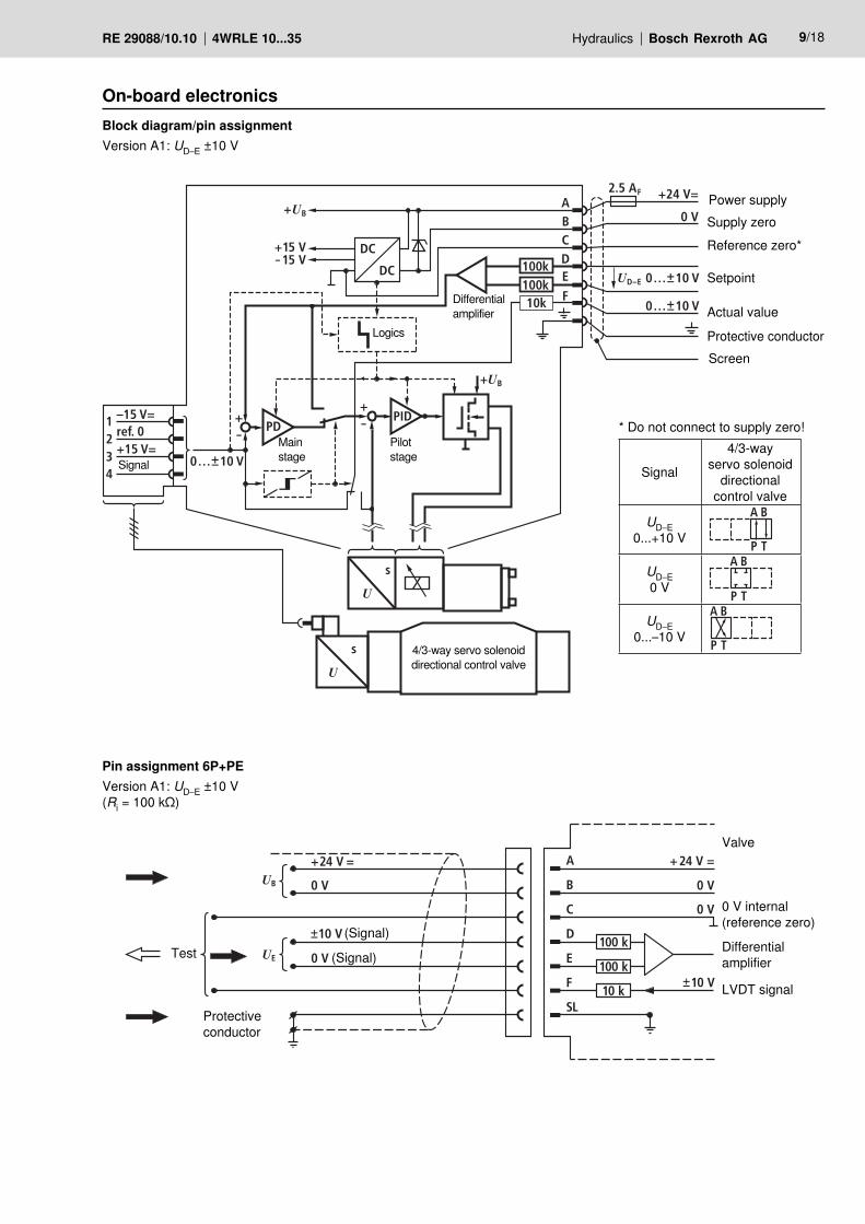
On-board electronicsBlock diagram/pin assignmentVersion A1: UD–E ±10 V
Pin assignment 6P+PEVersion A1: UD–E ±10 V(Ri = 100 kΩ)
Logics
Signal
Main stage
Pilot stage
4/3-way servo solenoid directional control valve
Differential amplifier
Power supplySupply zeroReference zero*
Setpoint
Actual value
Protective conductor Screen
* Do not connect to supply zero!
Signal
4/3-wayservo solenoid
directionalcontrol valve
UD–E0...+10 V
A B
P T
UD–E0 V
A B
P T
UD–E0...–10 V
A B
P T
Test(Signal)
(Signal)
Protective conductor
0 V internal(reference zero)
Differential amplifier
LVDT signal
Valve
PID+–PD
+–
U
s
U
s
+–0… 10 V
4…20 mAID–E
IF–C 4…20 mA
IF–C
+24 V =
0 V+UB
+UB
+15 V– 15 V
ABCDC
DCE
Rsh200 V
4…20 mAmA
V
F
D
1 –15 V=
2 ref. 0
3 +15 V=
4
2.5 AF
A +24 V =+24 V =
B 0 V0 V
C
D
E
F
SL
OUT
IN
SL
10 V
4…20 mA
I = 4…20 mA
Rsh =200 V
UB
10/18 Bosch Rexroth AG Hydraulics 4WRLE 10...35 RE 29088/10.10
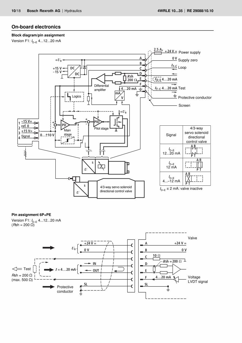
On-board electronicsBlock diagram/pin assignmentVersion F1: ID–E 4...12...20 mA
Pin assignment 6P+PEVersion F1: ID–E 4...12...20 mA(Rsh = 200 Ω)
Rsh = 200 Ω(max. 500 Ω)
Power supply
Supply zero
Loop
Test
Protective conductor
Screen
Logics
Signal
Main stage
Pilot stage
4/3-way servo solenoid directional control valve
Differential amplifier
Signal
4/3-wayservo solenoid
directionalcontrol valve
ID–E12...20 mA
A B
P T
ID–E12 mA
A B
P T
ID–E4...–12 mA
A B
P TID–E ≦ 2 mA: valve inactive
Test
Protective conductor
VoltageLVDT signal
Valve
100
60
80
40
20
-20
-60
-40
-80
-100
-10UD–E (V)
ID–E (mA)
-UD–E (V)
off 2 mA 4 12 20
-8 -6 -4 -22 4 6 8 10
1%
P-AB-T(1:1)
B-T(2:1)
Q (%)
Q (%)
ID–E (mA)
-UD–E (V)UD–E (V)
-20
-60
-40
-80
-100
-10
10% QN
10% QN-8 -6 -4
2 4 6 8 10-2
100
60
80
40
20
P-AB-T(1:1)
B-T(2:1)
off 2 mA 4 12 20
Q (%)
Q (%)
UD–E (V)
ID–E (mA)
-UD–E (V)
20
100
60
80
40
20
-20
-60
-40
-80
-100
-10
off 2 mA 4 12
-8 -6 -4 -22 4 6 8 10
P-AB-T(1:1)
B-T(2:1)
Q (%)
Q (%)
A B
P T X
G G
Y
UEab
DpA
pP
B
100
80
60
40
20
–20
–40
–60
–80
–100
–4 –3 –2 –1 1 2 3 4
DpB A (%pP)
DpB A (%pP)
UD–E (%)UD–E (%)
Hydraulics Bosch Rexroth AGRE 29088/10.10 4WRLE 10...35 11/18
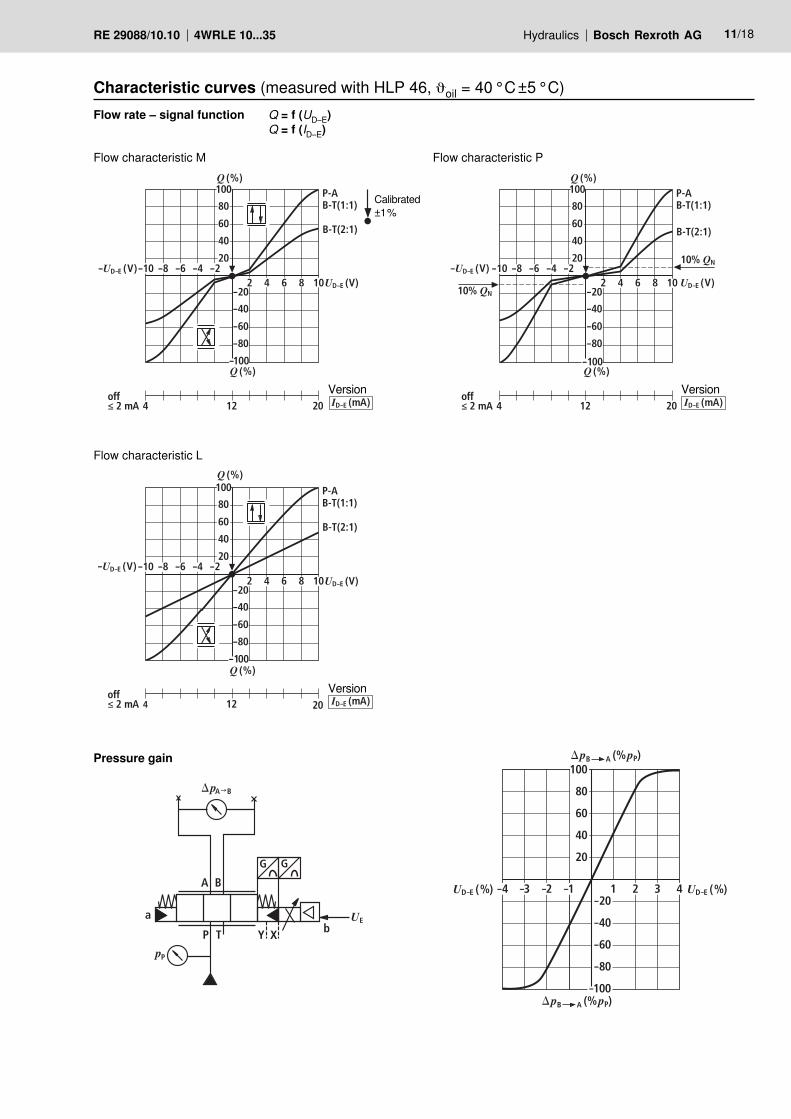
Characteristic curves (measured with HLP 46, oil = 40 °C ±5 °C)Flow rate – signal function Q = f (UD–E)
Q = f (ID–E)
Pressure gain
Calibrated±1 %
Flow characteristic M Flow characteristic P
Flow characteristic L
Version Version
Version
f (Hz)10 20 40 60 80 100 200 3000 20 40 60 80
–10–8–6–4
100 120 140
–202
160 180
1
200
pS = 100 bar
100%
5%
w
AB
dB 1
00%
5%
f (Hz)10 20 40 60 80 100 200 3000 20 40 60 80
–10–8–6–4
100 120 140
–202
160 180
1
200
pS = 100 bar
100%
5%
w
AB
dB
100
% 5%
f (Hz)10 20 40 60 80 100 200 3000 20 40 60 80
–10–8–6–4
100 120 140
–202
160 180
1
200
100%
5%
AB
dB
100
%
5%
pS = 100 bar w
f (Hz)10 20 40 60 80 100 200 3000 20 40 60 80
–10–8–6–4
100 120 140
–202
160 180
1
200 100%
5%
AB
dB
100%
5%
pS = 100 bar w
12/18 Bosch Rexroth AG Hydraulics 4WRLE 10...35 RE 29088/10.10
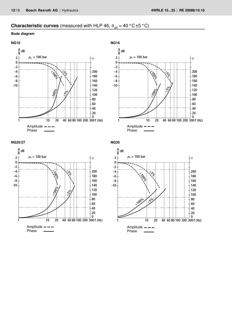
Characteristic curves (measured with HLP 46, oil = 40 °C ±5 °C)Bode diagram
NG10 NG16
NG25/27 NG35
Amplitude
Amplitude
Amplitude
Amplitude
Phase
Phase
Phase
Phase
T TA P BX Y
77
5 8 7 6 4
167
210 41
3
10281
49
39
33
ø6,6
30
70
8
5
197
105
46
1 2 9
24
10
72
P
T T1A B
F2F1
X Y
F3F4
25
13
104
0,01/100
Rzmax 4
Hydraulics Bosch Rexroth AGRE 29088/10.10 4WRLE 10...35 13/18
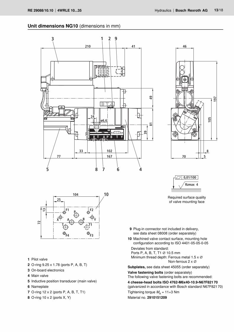
Unit dimensions NG10 (dimensions in mm)
1 Pilot valve2 O-ring 9.25 x 1.78 (ports P, A, B, T)3 On-board electronics4 Main valve5 Inductive position transducer (main valve)6 Nameplate7 O-ring 12 x 2 (ports P, A, B, T, T1)8 O-ring 10 x 2 (ports X, Y)
9 Plug-in connector not included in delivery, see data sheet 08008 (order separately)
10 Machined valve contact surface, mounting hole configuration according to ISO 4401-05-05-0-05
Deviates from standard:Ports P, A, B, T, T1 ∅ 10.5 mmMinimum thread depth: Ferrous metal 1.5 x ∅
Non-ferrous 2 x ∅Subplates, see data sheet 45055 (order separately)Valve fastening bolts (order separately)The following valve fastening bolts are recommended:4 cheese-head bolts ISO 4762-M6x40-10.9-N67F821 70(galvanized in accordance with Bosch standard N67F821 70)Tightening torque MA = 11+3 NmMaterial no. 2910151209
Required surface quality of valve mounting face
77
5 8 7 6 4
225
302
150
A B Y
9549
35
30
25
34
ø3 3
94
210
3
17
212
119
46
1 2 9
10
96
A B
T P
Y
X
F3F6G2F4
F2
G1
F1
F5
26
13
152
0,01/100
Rzmax 4
14/18 Bosch Rexroth AG Hydraulics 4WRLE 10...35 RE 29088/10.10
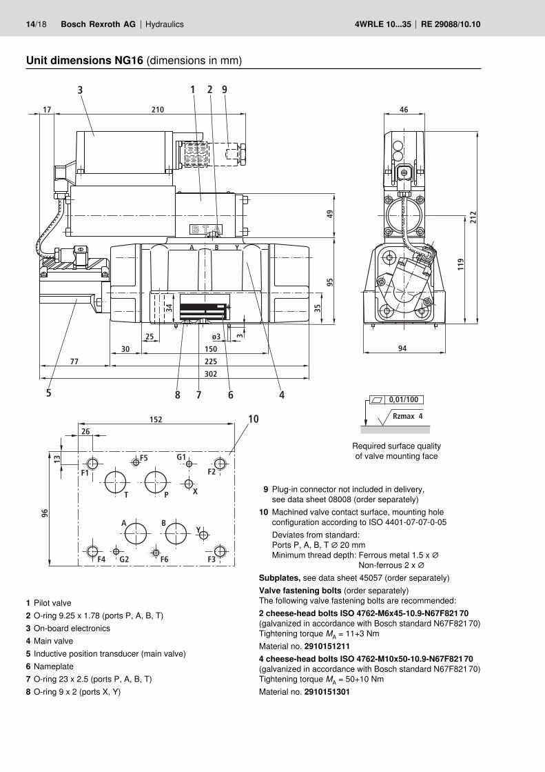
Unit dimensions NG16 (dimensions in mm)
1 Pilot valve2 O-ring 9.25 x 1.78 (ports P, A, B, T)3 On-board electronics4 Main valve5 Inductive position transducer (main valve)6 Nameplate7 O-ring 23 x 2.5 (ports P, A, B, T)8 O-ring 9 x 2 (ports X, Y)
9 Plug-in connector not included in delivery, see data sheet 08008 (order separately)
10 Machined valve contact surface, mounting hole configuration according to ISO 4401-07-07-0-05
Deviates from standard:Ports P, A, B, T ∅ 20 mmMinimum thread depth: Ferrous metal 1.5 x ∅
Non-ferrous 2 x ∅Subplates, see data sheet 45057 (order separately)Valve fastening bolts (order separately)The following valve fastening bolts are recommended:2 cheese-head bolts ISO 4762-M6x45-10.9-N67F821 70(galvanized in accordance with Bosch standard N67F821 70)Tightening torque MA = 11+3 NmMaterial no. 2910151211 4 cheese-head bolts ISO 4762-M10x50-10.9-N67F821 70(galvanized in accordance with Bosch standard N67F821 70)Tightening torque MA = 50+10 NmMaterial no. 2910151301
Required surface quality of valve mounting face
210
3
64
242
149
46
1 2 9
77
5 8 7 6 4
305382
190
A BX
125
4945
5718
ø13
43
ø66
118
10
118
A BX
T P Y
F3F6G2F4
F2
G1
F1
F5
20
13
194 0,01/100
Rzmax 4
Hydraulics Bosch Rexroth AGRE 29088/10.10 4WRLE 10...35 15/18
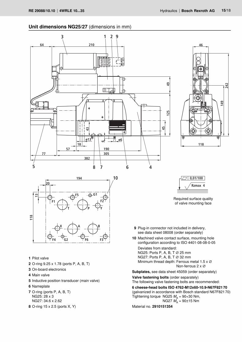
Unit dimensions NG25/27 (dimensions in mm)
1 Pilot valve2 O-ring 9.25 x 1.78 (ports P, A, B, T)3 On-board electronics4 Main valve5 Inductive position transducer (main valve)6 Nameplate7 O-ring (ports P, A, B, T)
NG25: 28 x 3NG27: 34.6 x 2.62
8 O-ring 15 x 2.5 (ports X, Y)
9 Plug-in connector not included in delivery, see data sheet 08008 (order separately)
10 Machined valve contact surface, mounting hole configuration according to ISO 4401-08-08-0-05
Deviates from standard:NG25: Ports P, A, B, T ∅ 25 mmNG27: Ports P, A, B, T ∅ 32 mmMinimum thread depth: Ferrous metal 1.5 x ∅
Non-ferrous 2 x ∅Subplates, see data sheet 45059 (order separately)Valve fastening bolts (order separately)The following valve fastening bolts are recommended:6 cheese-head bolts ISO 4762-M12x60-10.9-N67F821 70(galvanized in accordance with Bosch standard N67F821 70)Tightening torque NG25 MA = 90+30 Nm,
NG27 MA = 90±15 NmMaterial no. 2910151354
Required surface quality of valve mounting face
77
5 8 7 6 4
458320
A BX
4929
90
69
60
5
200
225
370
ø6
ø21
210
360
1 2 9
43,2
10
203
A BX
T P Y
F3F6G2
F4
F2G1
F1 F5
45
22
3240,01/100
Rzmax 4
16/18 Bosch Rexroth AG Hydraulics 4WRLE 10...35 RE 29088/10.10
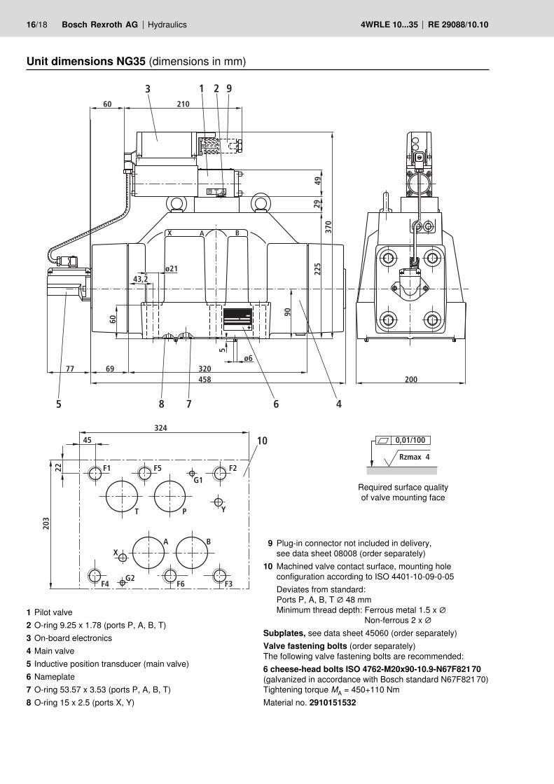
Unit dimensions NG35 (dimensions in mm)
Required surface quality of valve mounting face
1 Pilot valve2 O-ring 9.25 x 1.78 (ports P, A, B, T)3 On-board electronics4 Main valve5 Inductive position transducer (main valve)6 Nameplate7 O-ring 53.57 x 3.53 (ports P, A, B, T)8 O-ring 15 x 2.5 (ports X, Y)
9 Plug-in connector not included in delivery, see data sheet 08008 (order separately)
10 Machined valve contact surface, mounting hole configuration according to ISO 4401-10-09-0-05
Deviates from standard:Ports P, A, B, T ∅ 48 mmMinimum thread depth: Ferrous metal 1.5 x ∅
Non-ferrous 2 x ∅Subplates, see data sheet 45060 (order separately)Valve fastening bolts (order separately)The following valve fastening bolts are recommended:6 cheese-head bolts ISO 4762-M20x90-10.9-N67F821 70(galvanized in accordance with Bosch standard N67F821 70)Tightening torque MA = 450+110 NmMaterial no. 2910151532

Hydraulics Bosch Rexroth AGRE 29088/10.10 4WRLE 10...35 17/18
Notes

18/18 Bosch Rexroth AG Hydraulics 4WRLE 10...35 RE 29088/10.10
Bosch Rexroth AGHydraulicsZum Eisengießer 197816 Lohr am Main, GermanyTelefon +49 (0) 93 52 / 18-0Telefax +49 (0) 93 52 / 18-23 [email protected]
© This document, as well as the data, specifications and other information set forth in it, are the exclusive property of Bosch Rexroth AG. It may not be reproduced or given to third parties without its consent.The data specified above only serve to describe the product. No state- ments concerning a certain condition or suitability for a certain application can be derived from our information. The information given does not release the user from the obligation of own judgment and verification. It must be remembered that our products are subject to a natural process of wear and aging.
Notes
Hydraulics Bosch Rexroth AGRE 29088/10.10 4WRLE 10...35
Bosch Rexroth AGHydraulicsZum Eisengießer 197816 Lohr am Main, GermanyTelefon +49 (0) 93 52 / 18-0Telefax +49 (0) 93 52 / 18-23 [email protected]
© This document, as well as the data, specifications and other information set forth in it, are the exclusive property of Bosch Rexroth AG. It may not be reproduced or given to third parties without its consent.The data specified above only serve to describe the product. No state- ments concerning a certain condition or suitability for a certain application can be derived from our information. The information given does not release the user from the obligation of own judgment and verification. It must be remembered that our products are subject to a natural process of wear and aging.
Notes
4WRLE 10...35 RE 29088/10.10
Bosch Rexroth AGHydraulicsZum Eisengießer 197816 Lohr am Main, GermanyTelefon +49 (0) 93 52 / 18-0Telefax +49 (0) 93 52 / 18-23 [email protected]
© This document, as well as the data, specifications and other information set forth in it, are the exclusive property of Bosch Rexroth AG. It may not be reproduced or given to third parties without its consent.The data specified above only serve to describe the product. No state- ments concerning a certain condition or suitability for a certain application can be derived from our information. The information given does not release the user from the obligation of own judgment and verification. It must be remembered that our products are subject to a natural process of wear and aging.
Bosch Rexroth AG Hydraulics
Notes