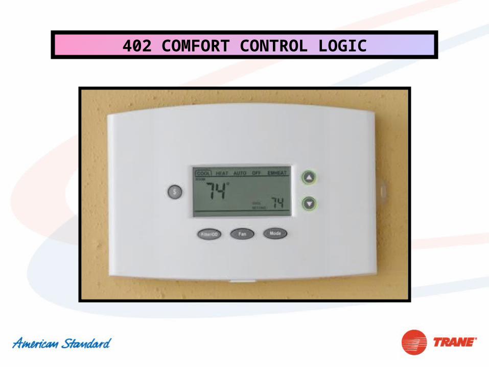
402 COMFORT CONTROL LOGIC. Questions SUB BASE Up to 16 wires may be required.
28
402 COMFORT CONTROL LOGIC
-
Upload
bret-kettell -
Category
Documents
-
view
218 -
download
0
Transcript of 402 COMFORT CONTROL LOGIC. Questions SUB BASE Up to 16 wires may be required.
402 COMFORT CONTROL LOGIC
Questions
SUB BASE
Up to 16 wires may be requiredUp to 16 wires may be required
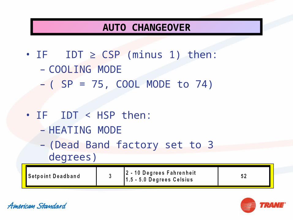
AUTO CHANGEOVER
• IF IDT ≥ CSP (minus 1) then: – COOLING MODE – ( SP = 75, COOL MODE to 74)
• IF IDT < HSP then: – HEATING MODE – (Dead Band factory set to 3 degrees)
LOAD VALUE
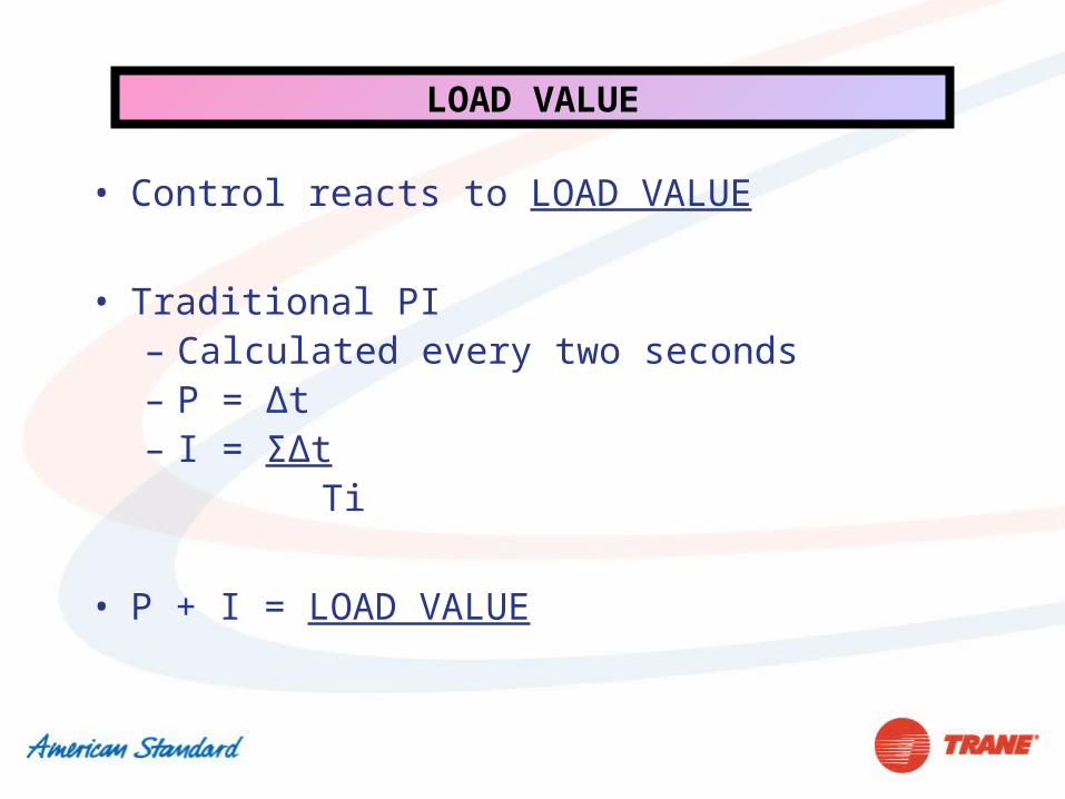
• Control reacts to LOAD VALUE
• Traditional PI– Calculated every two seconds– P = Δt– I = ΣΔt Ti
• P + I = LOAD VALUE
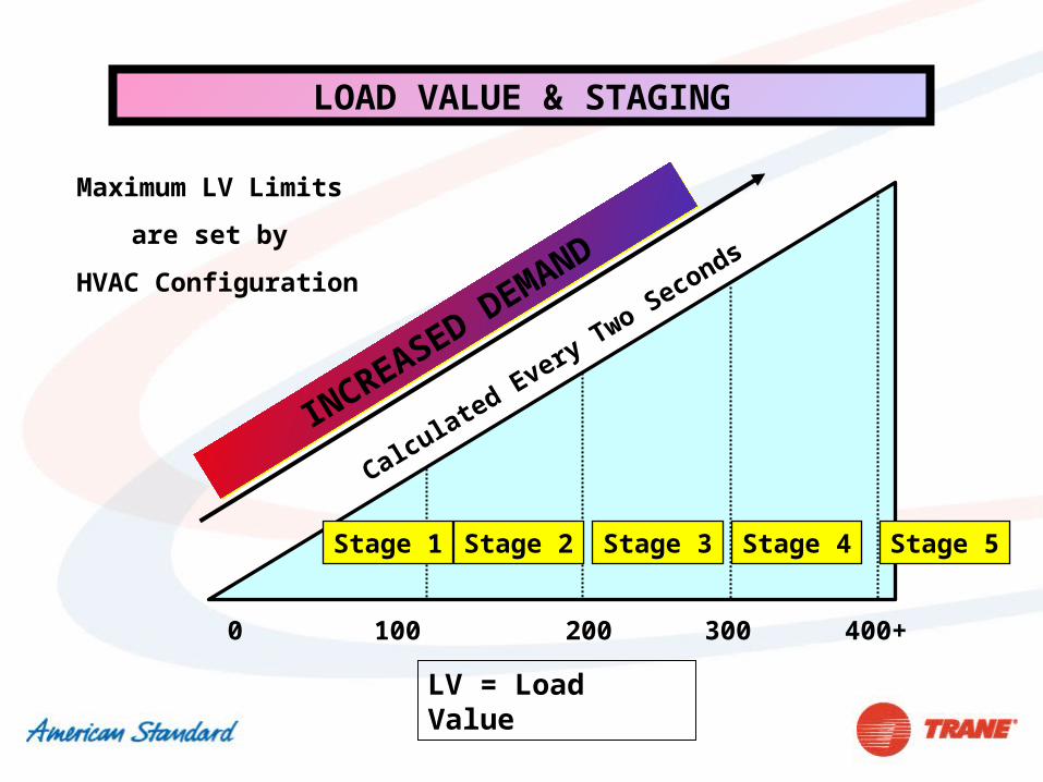
LOAD VALUE & STAGING
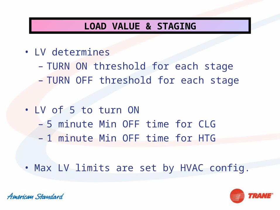
• LV determines – TURN ON threshold for each stage– TURN OFF threshold for each stage
• LV of 5 to turn ON– 5 minute Min OFF time for CLG– 1 minute Min OFF time for HTG
• Max LV limits are set by HVAC config.
LOAD VALUE & STAGING
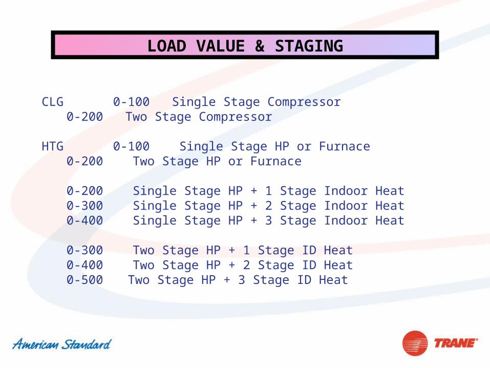
CLG 0-100 Single Stage Compressor 0-200 Two Stage Compressor
HTG 0-100 Single Stage HP or Furnace 0-200 Two Stage HP or Furnace 0-200 Single Stage HP + 1 Stage Indoor Heat 0-300 Single Stage HP + 2 Stage Indoor Heat 0-400 Single Stage HP + 3 Stage Indoor Heat 0-300 Two Stage HP + 1 Stage ID Heat 0-400 Two Stage HP + 2 Stage ID Heat 0-500 Two Stage HP + 3 Stage ID Heat
LOAD VALUE & STAGING
3002000 100 400+
LV = Load Value
Calculated Every Two Seconds
INCREASED DEMAND
INCREASED DEMAND
Stage 1 Stage 2 Stage 3 Stage 4
Maximum LV Limits
are set by
HVAC Configuration
Stage 5
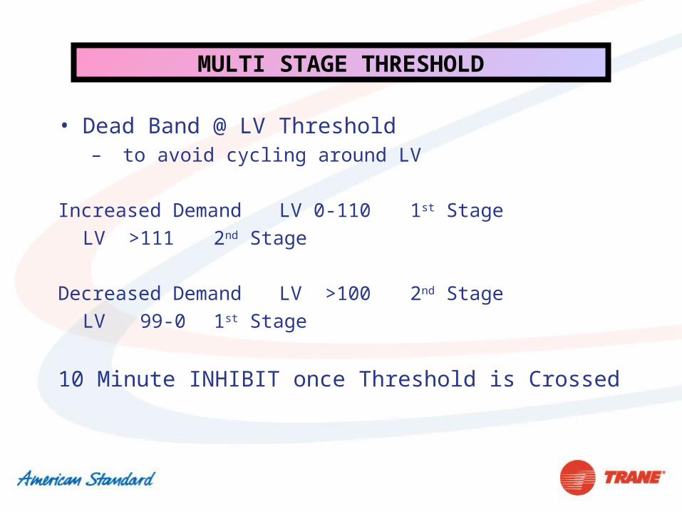
MULTI STAGE THRESHOLD
• Dead Band @ LV Threshold – to avoid cycling around LV
Increased Demand LV 0-110 1st StageLV >111 2nd Stage
Decreased Demand LV >100 2nd StageLV 99-0 1st Stage
10 Minute INHIBIT once Threshold is Crossed
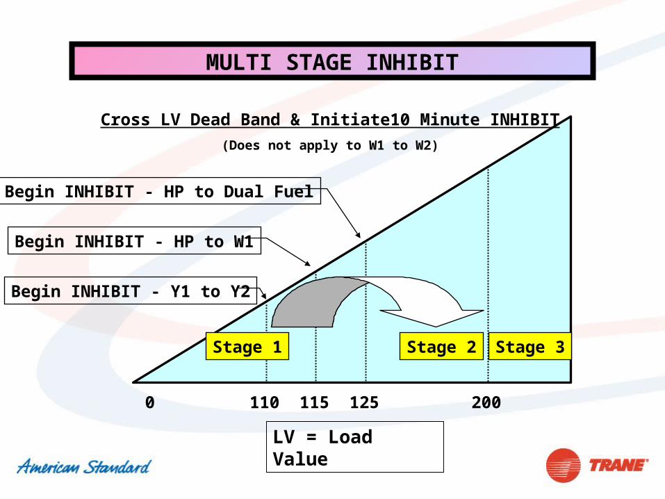
2000 110
Stage 1 Stage 2
Cross LV Dead Band & Initiate10 Minute INHIBIT
(Does not apply to W1 to W2)
Stage 3
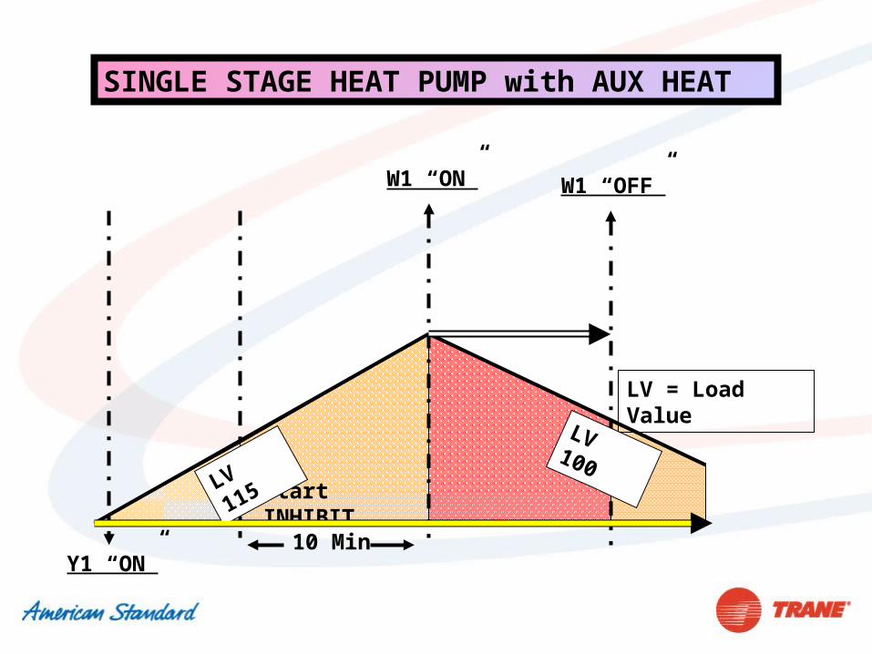
115 125
LV = Load Value
Begin INHIBIT - Y1 to Y2
Begin INHIBIT - HP to W1
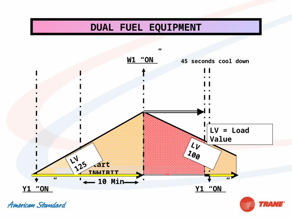
Begin INHIBIT - HP to Dual Fuel
MULTI STAGE INHIBIT
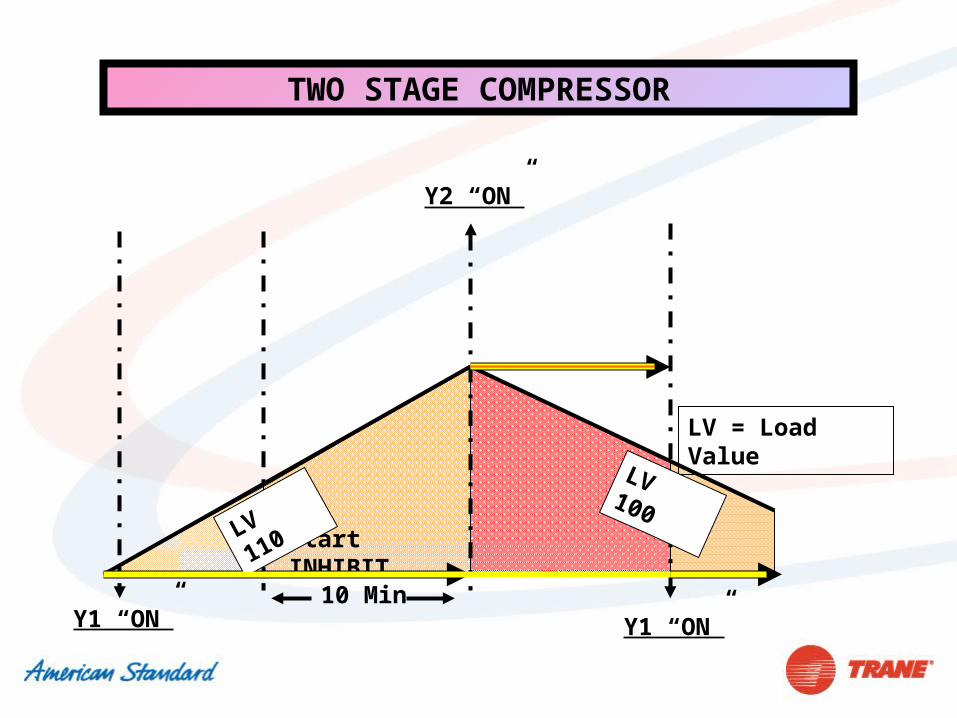
TWO STAGE COMPRESSOR
Y1 “ON”
Start INHIBIT
Y2 “ON”
10 Min
LV = Load Value
LV 110
Y1 “ON”
LV 100
Y1 “ON”
Start INHIBIT
10 Min
LV = Load Value
LV 115LV 100
SINGLE STAGE HEAT PUMP with AUX HEAT
W1 “ON” W1 “OFF”
Y1 “ON”
Start INHIBIT
10 Min
LV 125
Y1 “ON”
DUAL FUEL EQUIPMENT
W1 “ON” 45 seconds cool down
LV 100
LV = Load Value
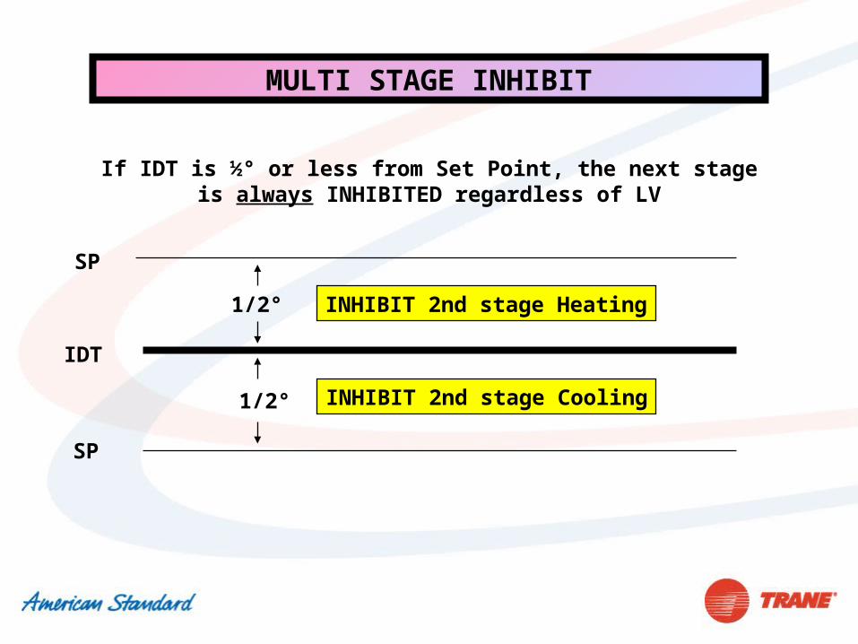
MULTI STAGE INHIBIT
If IDT is ½° or less from Set Point, the next stage is always INHIBITED regardless of LV
IDT
SP
1/2° INHIBIT 2nd stage Cooling
1/2°
SP
INHIBIT 2nd stage Heating
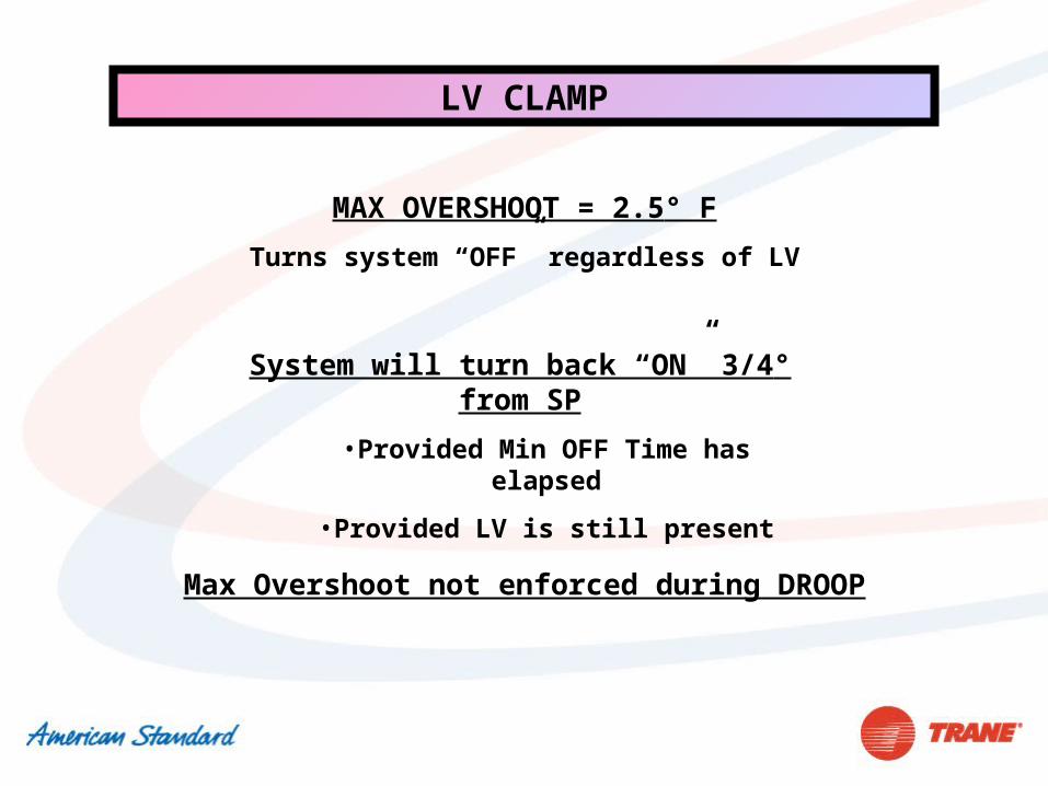
LV CLAMP
MAX OVERSHOOT = 2.5° F
Turns system “OFF” regardless of LV
System will turn back “ON” 3/4° from SP
•Provided Min OFF Time has elapsed
•Provided LV is still present
Max Overshoot not enforced during DROOP

COOLING DROOP
•Set Point is satisfied (No-load or light load condition)
•Time OFF satisfied
•IDT < Droop OVERSHOOT limit to start DROOP “ON” cycle
•Standard DROOP = 1 degree OVERSHOOT
•Enhanced DROOP = 2 degree OVERSHOOT
•Fan delay-to-OFF is cancelled
•Var Sp: Blower speed set to 80% (BK= 70% PWM)
•Minimum ON = 8 minutes
•Minimum OFF = 20 minutes
SET POINT CHANGES
• Temperature Display Rounds to Nearest Whole Number
• Room Sensor can Discern 10ths of a Degree – – Used to Calculate Temp Difference from SP
• Large Changes in SP will Freeze LV until New SP is Reached to Avoid Overshoot– “Snap Shot & Roll Back”
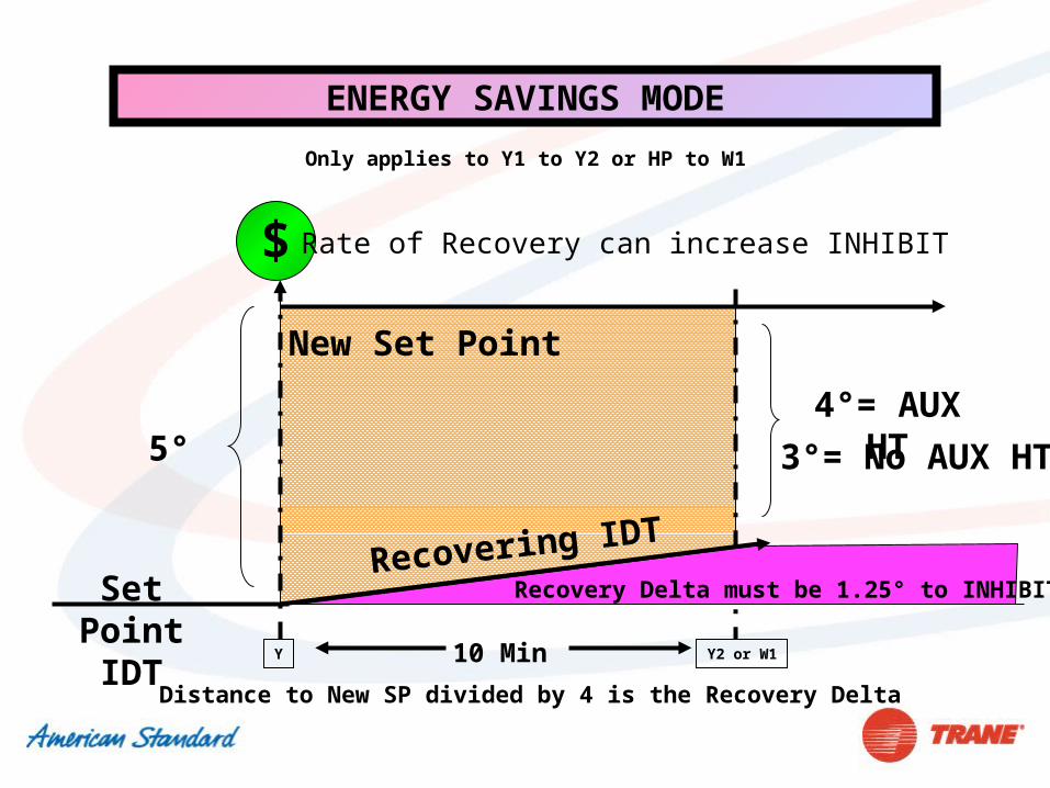
$
10 Min
Set PointIDT
5°
New Set Point
4°= AUX HT 3°= No AUX HT
Recovering IDT
ENERGY SAVINGS MODE
Rate of Recovery can increase INHIBIT
Only applies to Y1 to Y2 or HP to W1
Recovery Delta must be 1.25° to INHIBIT
Distance to New SP divided by 4 is the Recovery Delta
Y2 or W1Y

$
10 Min
Set PointIDT
10°
New Set Point
8°= AUX HT 7°= No AUX HT
Recovering IDT
ENERGY SAVINGS MODE
Rate of Recovery can increase INHIBIT
Only applies to Y1 to Y2 or HP to W1
Recovery Delta must be 2.5° to INHIBIT
Distance to New SP divided by 4 is the Recovery Delta
Y Y2 or W1
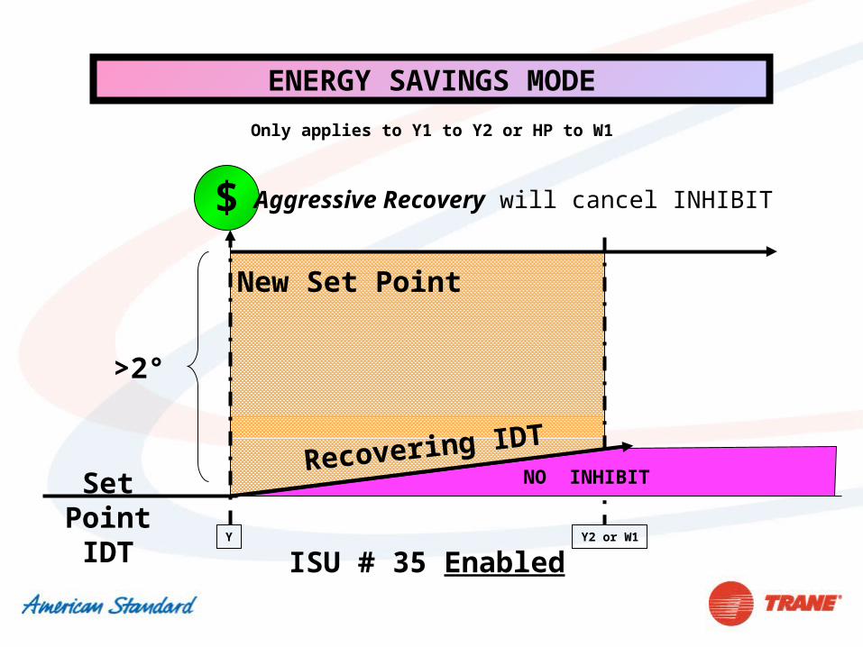
$
Set PointIDT
>2°
New Set Point
Recovering IDT
ENERGY SAVINGS MODE
Aggressive Recovery will cancel INHIBIT
Only applies to Y1 to Y2 or HP to W1
NO INHIBIT
ISU # 35 EnabledY Y2 or W1
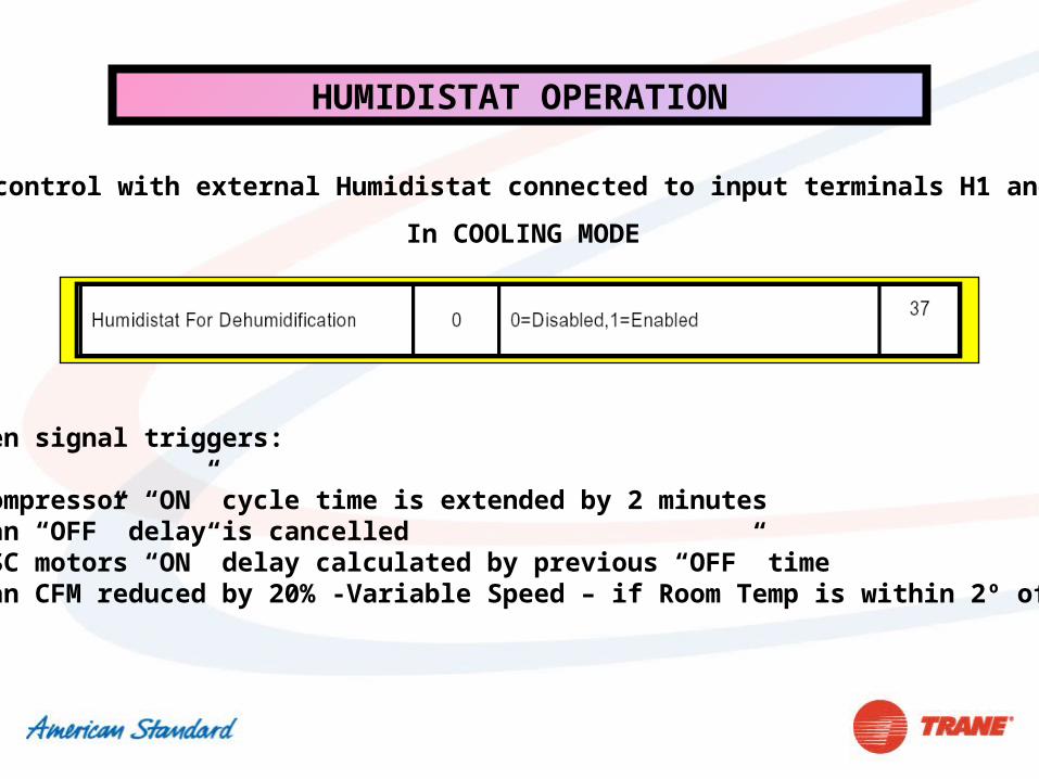
HUMIDISTAT OPERATION
RH control with external Humidistat connected to input terminals H1 and H2
In COOLING MODE
Open signal triggers:
•Compressor “ON” cycle time is extended by 2 minutes•Fan “OFF” delay is cancelled •PSC motors “ON” delay calculated by previous “OFF” time •Fan CFM reduced by 20% -Variable Speed – if Room Temp is within 2º of SP
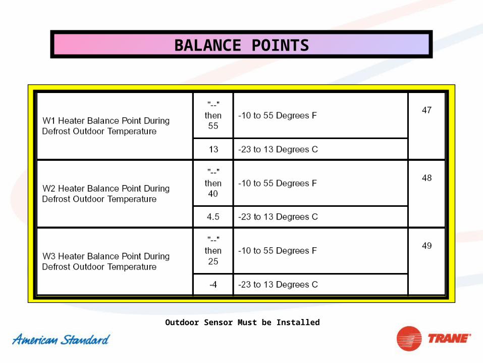
BALANCE POINTS
Outdoor Sensor Must be Installed
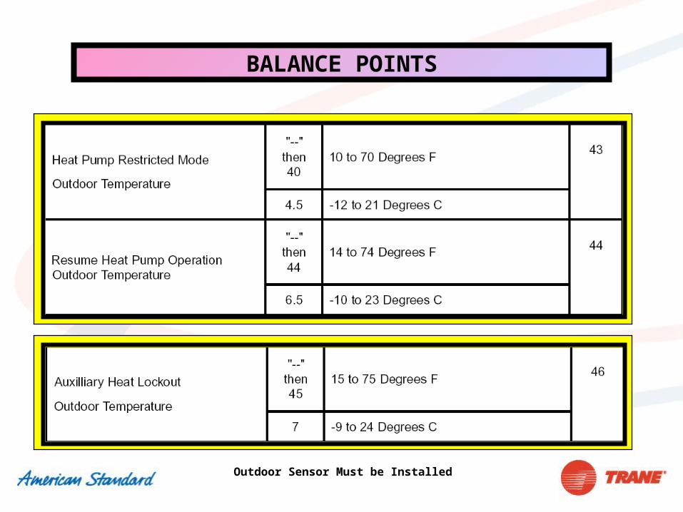
BALANCE POINTS
Outdoor Sensor Must be Installed
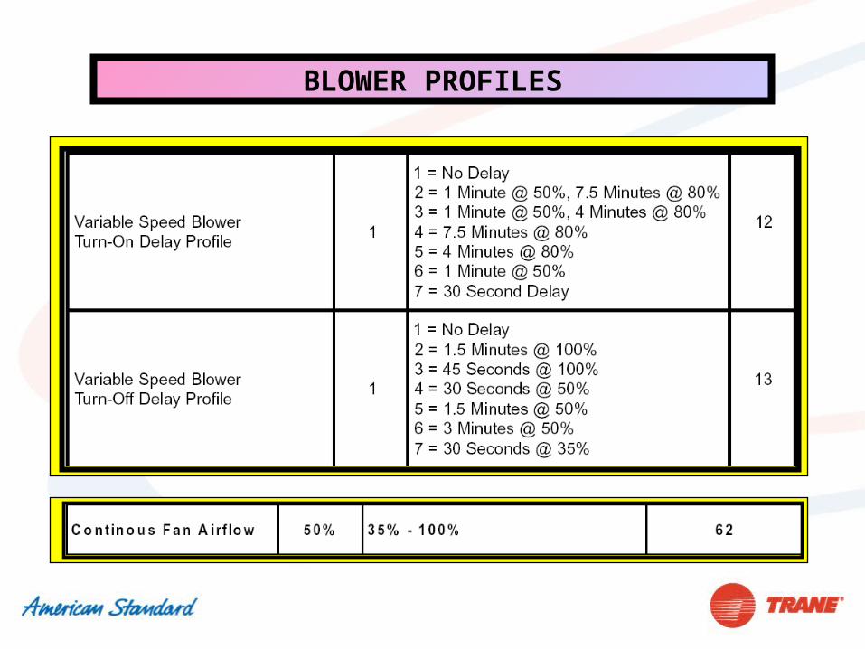
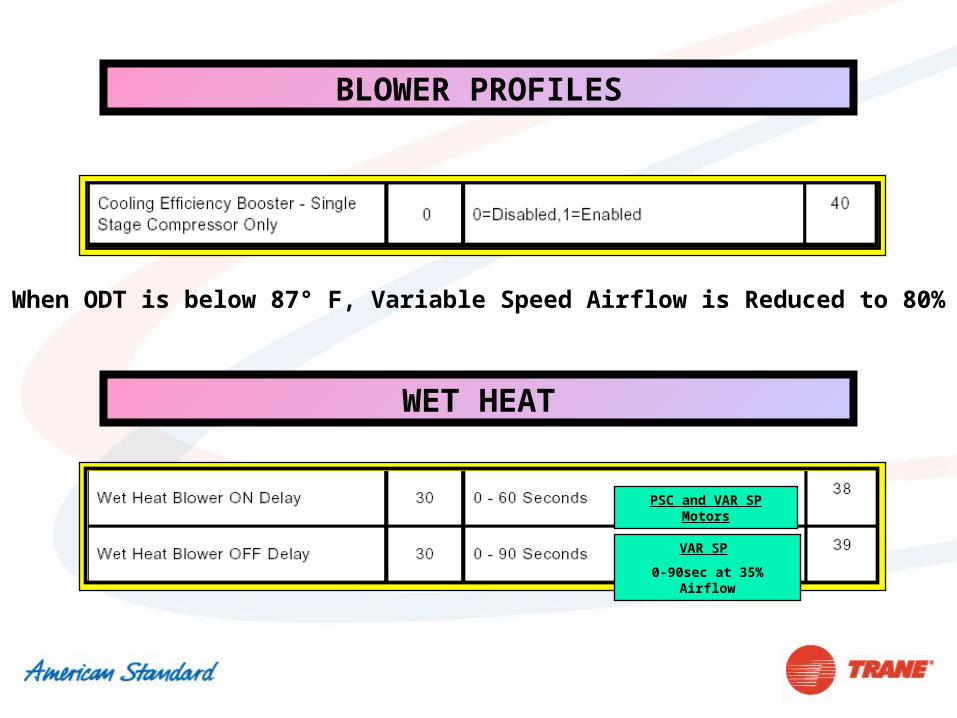
BLOWER PROFILES
BLOWER PROFILES
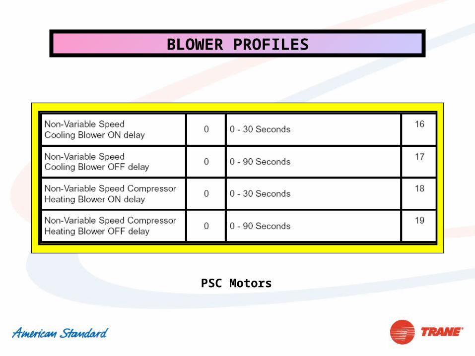
PSC Motors
BLOWER PROFILES
When ODT is below 87° F, Variable Speed Airflow is Reduced to 80%
WET HEAT
VAR SP
0-90sec at 35% Airflow
PSC and VAR SP Motors
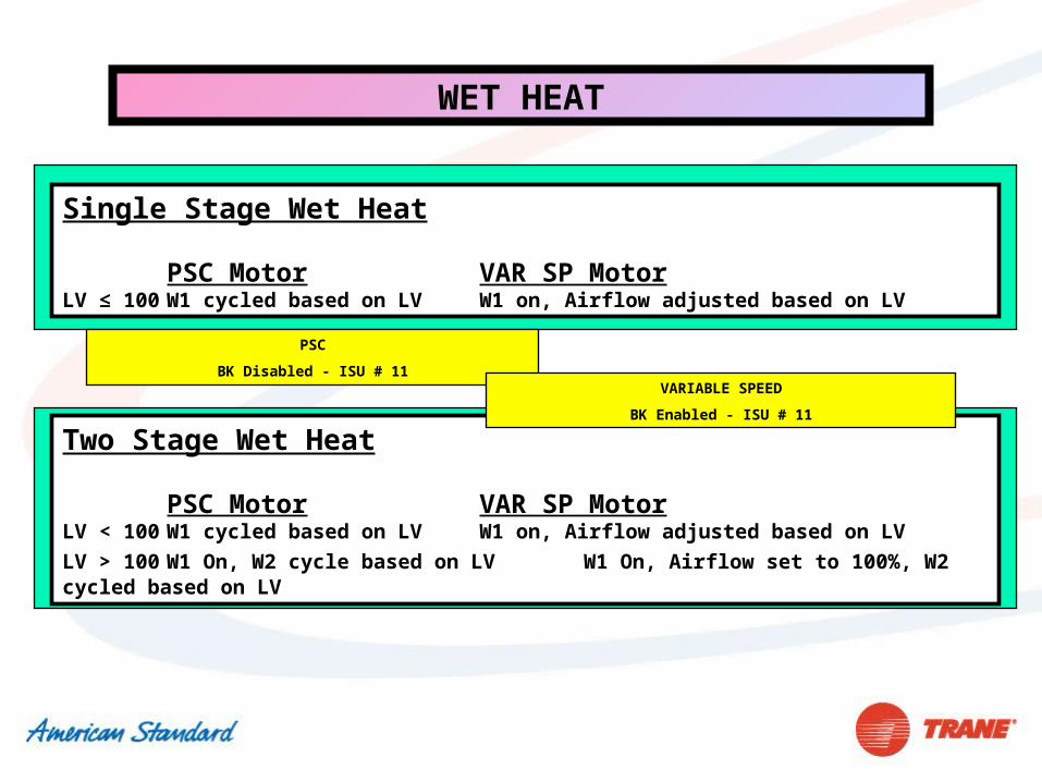
WET HEAT
Single Stage Wet Heat
PSC Motor VAR SP MotorLV ≤ 100 W1 cycled based on LV W1 on, Airflow adjusted based on LV
Two Stage Wet Heat
PSC Motor VAR SP MotorLV < 100 W1 cycled based on LV W1 on, Airflow adjusted based on LV
LV > 100 W1 On, W2 cycle based on LV W1 On, Airflow set to 100%, W2 cycled based on LV
PSC
BK Disabled - ISU # 11VARIABLE SPEED
BK Enabled - ISU # 11
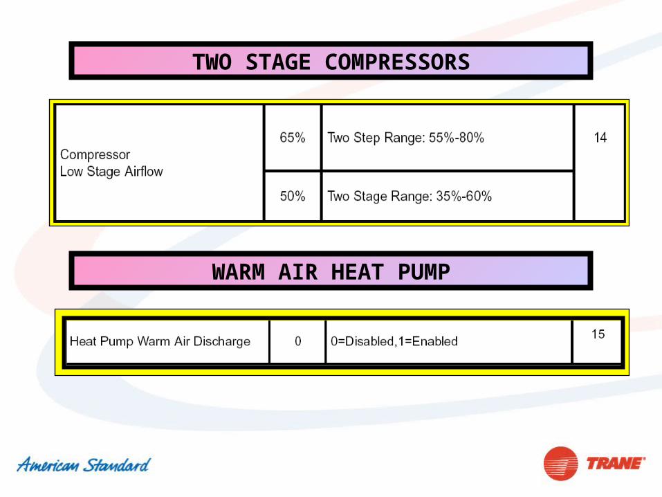
TWO STAGE COMPRESSORS
WARM AIR HEAT PUMP
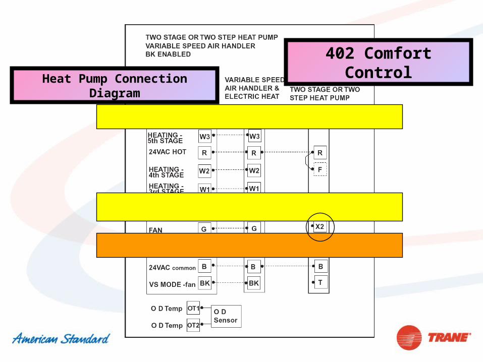
402 Comfort Control
Heat Pump Connection Diagram


![Radical Cation π‐Dimers of Conjugated Oligomers as ... › contents › ... · transport through molecular wires has been pointed out.[43-47] This intimate relationship was deduced](https://static.fdocument.org/doc/165x107/5f0c70957e708231d43568ca/radical-cation-adimers-of-conjugated-oligomers-as-a-contents-a-.jpg)