4 ACCELERATOR OVERVIEW - Brookhaven National · PDF file226 beam position monitors (seven BPMs...
17
Chapter 4: Accelerator Overview 4-1 NSLS-II Conceptual Design Report 4 ACCELERATOR OVERVIEW This chapter describes the main requirements and features of the NSLS-II accelerator complex, focusing on the philosophy and the approach used to select the NSLS-II ring lattice, injection scheme, and main components. Based on the considerations presented here, we believe we have arrived at an optimal, or near- optimal, design. This description is brief, and important details of the individual systems and subsystems are presented in other chapters of this CDR. Figure 4.1.1 Schematic layout of the NSLS-II accelerators: a 200 MeV linac, a 3 GeV booster ring, and the 3 GeV storage ring. The booster and the storage ring share the same tunnel. 4.1 Scope of the Accelerator Complex NSLS-II is designed to deliver photons with average spectral brightness in the 2 keV to 10 keV energy range exceeding 10 21 ph/mm 2 /mrad 2 /s/0.1%BW. The spectral flux density should exceed 10 15 ph/s/0.1%BW in all spectral ranges and with a peak value approaching 10 16 ph/s/0.1%BW for photon energies around 2 keV. This cutting-edge performance requires the storage ring to support a very high-current electron beam (I = 500 mA) with sub-nm-rad horizontal emittance (down to 0.5 nm-rad) and diffraction-limited vertical emittance at a wavelength of 1 Å (vertical emittance <8 pm-rad). The electron beam will be stable in its position (<10% of its size), angle (<10% of its divergence), dimensions (<10%), and intensity (±0.5% variation). The latter requirement provides for constant thermal load on the beamline front ends.
Transcript of 4 ACCELERATOR OVERVIEW - Brookhaven National · PDF file226 beam position monitors (seven BPMs...
Chapter 4: Accelerator Overview 4-1
NSLS-II Conceptual Design Report
4 ACCELERATOR OVERVIEW
This chapter describes the main requirements and features of the NSLS-II accelerator complex, focusing on the philosophy and the approach used to select the NSLS-II ring lattice, injection scheme, and main components. Based on the considerations presented here, we believe we have arrived at an optimal, or near-optimal, design. This description is brief, and important details of the individual systems and subsystems are presented in other chapters of this CDR.
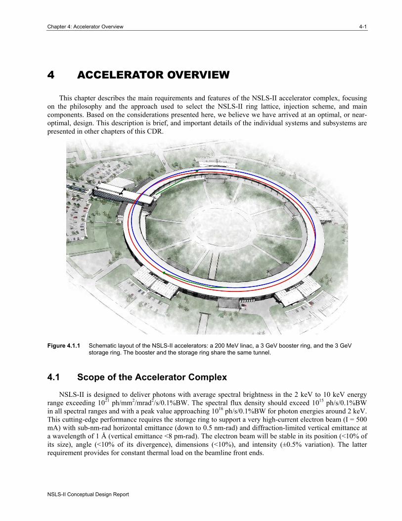
Figure 4.1.1 Schematic layout of the NSLS-II accelerators: a 200 MeV linac, a 3 GeV booster ring, and the 3 GeV storage ring. The booster and the storage ring share the same tunnel.
4.1 Scope of the Accelerator Complex
NSLS-II is designed to deliver photons with average spectral brightness in the 2 keV to 10 keV energy range exceeding 1021 ph/mm2/mrad2/s/0.1%BW. The spectral flux density should exceed 1015 ph/s/0.1%BW in all spectral ranges and with a peak value approaching 1016 ph/s/0.1%BW for photon energies around 2 keV. This cutting-edge performance requires the storage ring to support a very high-current electron beam (I = 500 mA) with sub-nm-rad horizontal emittance (down to 0.5 nm-rad) and diffraction-limited vertical emittance at a wavelength of 1 Å (vertical emittance <8 pm-rad). The electron beam will be stable in its position (<10% of its size), angle (<10% of its divergence), dimensions (<10%), and intensity (±0.5% variation). The latter requirement provides for constant thermal load on the beamline front ends.
4-2 NSLS-II Conceptual Design Report
Brookhaven National Laboratory
A schematic layout of the NSLS-II accelerators is shown in Figure 4.1.1. Electrons generated in the linac are accelerated to 3 GeV in the booster. The accelerated electrons are periodically added to the electron beam circulating in the storage ring to keep the stored current nearly constant in time, a process know as top-off injection. This chapter presents the main parameters of the accelerator systems and main subsystems for NSLS-II and descriptions of the considerations and process that led to their optimization.
4.1.1 Physics Design and Parameters of NSLS-II
4.1.1.1 Storage Ring Everywhere possible, NSLS-II will use known, reliable, and cost-effective solutions for its subsystems.
Examples of such subsystems extend from a simple low-energy linac to the ring and booster RF systems, which are commercially available. Subsystems that are not critical to NSLS-II performance will be based on the simplest, most robust, and best-proven technologies. Hence, all magnetic elements of the accelerators have a significant margin in their design, but are not over-designed. Only the few subsystems that are crucial for attaining the ultimate NSLS-II performance require cutting-edge technologies and engineering solutions.
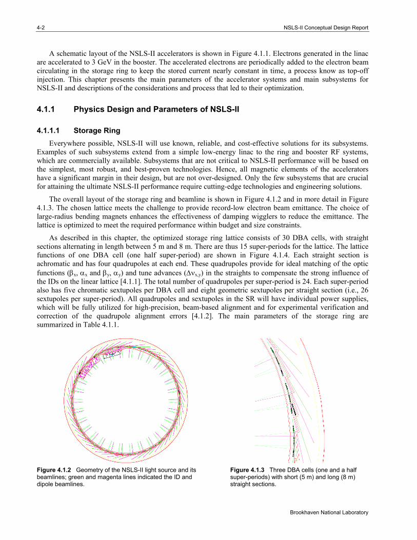
The overall layout of the storage ring and beamline is shown in Figure 4.1.2 and in more detail in Figure 4.1.3. The chosen lattice meets the challenge to provide record-low electron beam emittance. The choice of large-radius bending magnets enhances the effectiveness of damping wigglers to reduce the emittance. The lattice is optimized to meet the required performance within budget and size constraints.
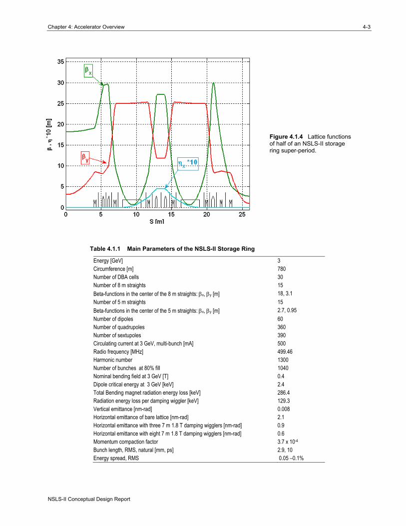
As described in this chapter, the optimized storage ring lattice consists of 30 DBA cells, with straight sections alternating in length between 5 m and 8 m. There are thus 15 super-periods for the lattice. The lattice functions of one DBA cell (one half super-period) are shown in Figure 4.1.4. Each straight section is achromatic and has four quadrupoles at each end. These quadrupoles provide for ideal matching of the optic functions (βx, αx and βy, αy) and tune advances (Δνx,y) in the straights to compensate the strong influence of the IDs on the linear lattice [4.1.1]. The total number of quadrupoles per super-period is 24. Each super-period also has five chromatic sextupoles per DBA cell and eight geometric sextupoles per straight section (i.e., 26 sextupoles per super-period). All quadrupoles and sextupoles in the SR will have individual power supplies, which will be fully utilized for high-precision, beam-based alignment and for experimental verification and correction of the quadrupole alignment errors [4.1.2]. The main parameters of the storage ring are summarized in Table 4.1.1.
Figure 4.1.2 Geometry of the NSLS-II light source and its beamlines; green and magenta lines indicated the ID and dipole beamlines.
Figure 4.1.3 Three DBA cells (one and a half super-periods) with short (5 m) and long (8 m) straight sections.
Chapter 4: Accelerator Overview 4-3
NSLS-II Conceptual Design Report
Figure 4.1.4 Lattice functions of half of an NSLS-II storage ring super-period.
Table 4.1.1 Main Parameters of the NSLS-II Storage Ring
Energy [GeV] 3 Circumference [m] 780 Number of DBA cells 30 Number of 8 m straights 15 Beta-functions in the center of the 8 m straights: βx, βy [m] 18, 3.1 Number of 5 m straights 15 Beta-functions in the center of the 5 m straights: βx, βy [m] 2.7, 0.95 Number of dipoles 60 Number of quadrupoles 360 Number of sextupoles 390 Circulating current at 3 GeV, multi-bunch [mA] 500 Radio frequency [MHz] 499.46 Harmonic number 1300 Number of bunches at 80% fill 1040 Nominal bending field at 3 GeV [T] 0.4 Dipole critical energy at 3 GeV [keV] 2.4 Total Bending magnet radiation energy loss [keV] 286.4 Radiation energy loss per damping wiggler [keV] 129.3 Vertical emittance [nm-rad] 0.008 Horizontal emittance of bare lattice [nm-rad] 2.1 Horizontal emittance with three 7 m 1.8 T damping wigglers [nm-rad] 0.9 Horizontal emittance with eight 7 m 1.8 T damping wigglers [nm-rad] 0.6 Momentum compaction factor 3.7 x 10⁻⁴ Bunch length, RMS, natural [mm, ps] 2.9, 10 Energy spread, RMS 0.05 –0.1%
4-4 NSLS-II Conceptual Design Report
Brookhaven National Laboratory
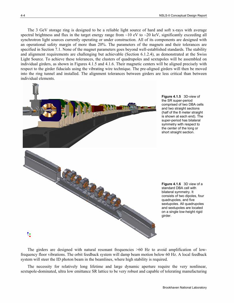
The 3 GeV storage ring is designed to be a reliable light source of hard and soft x-rays with average spectral brightness and flux in the target energy range from ~10 eV to ~20 keV, significantly exceeding all synchrotron light sources currently operating or under construction. All of its components are designed with an operational safety margin of more than 20%. The parameters of the magnets and their tolerances are specified in Section 7.1. None of the magnet parameters goes beyond well-established standards. The stability and alignment requirements are challenging but achievable (Section 6.1.2.4), as demonstrated at the Swiss Light Source. To achieve these tolerances, the clusters of quadrupoles and sextupoles will be assembled on individual girders, as shown in Figures 4.1.5 and 4.1.6. Their magnetic centers will be aligned precisely with respect to the girder fiducials using the vibrating wire technique. The pre-aligned girders will then be moved into the ring tunnel and installed. The alignment tolerances between girders are less critical than between individual elements.
Figure 4.1.5 3D-view of the SR super-period comprised of two DBA cells and two straight sections (half of the 8 meter straight is shown at each end). The super-period has bilateral symmetry with respect to the center of the long or short straight section.
Figure 4.1.6 3D view of a standard DBA cell with bilateral symmetry. It consists of two dipoles, four quadrupoles, and five sextupoles. All quadrupoles and sextupoles are located on a single low-height rigid girder.
The girders are designed with natural resonant frequencies >60 Hz to avoid amplification of low-frequency floor vibrations. The orbit feedback system will damp beam motion below 60 Hz. A local feedback system will steer the ID photon beam in the beamlines, where high stability is required.
The necessity for relatively long lifetime and large dynamic aperture require the very nonlinear, sextupole-dominated, ultra low emittance SR lattice to be very robust and capable of tolerating manufacturing
Chapter 4: Accelerator Overview 4-5
NSLS-II Conceptual Design Report
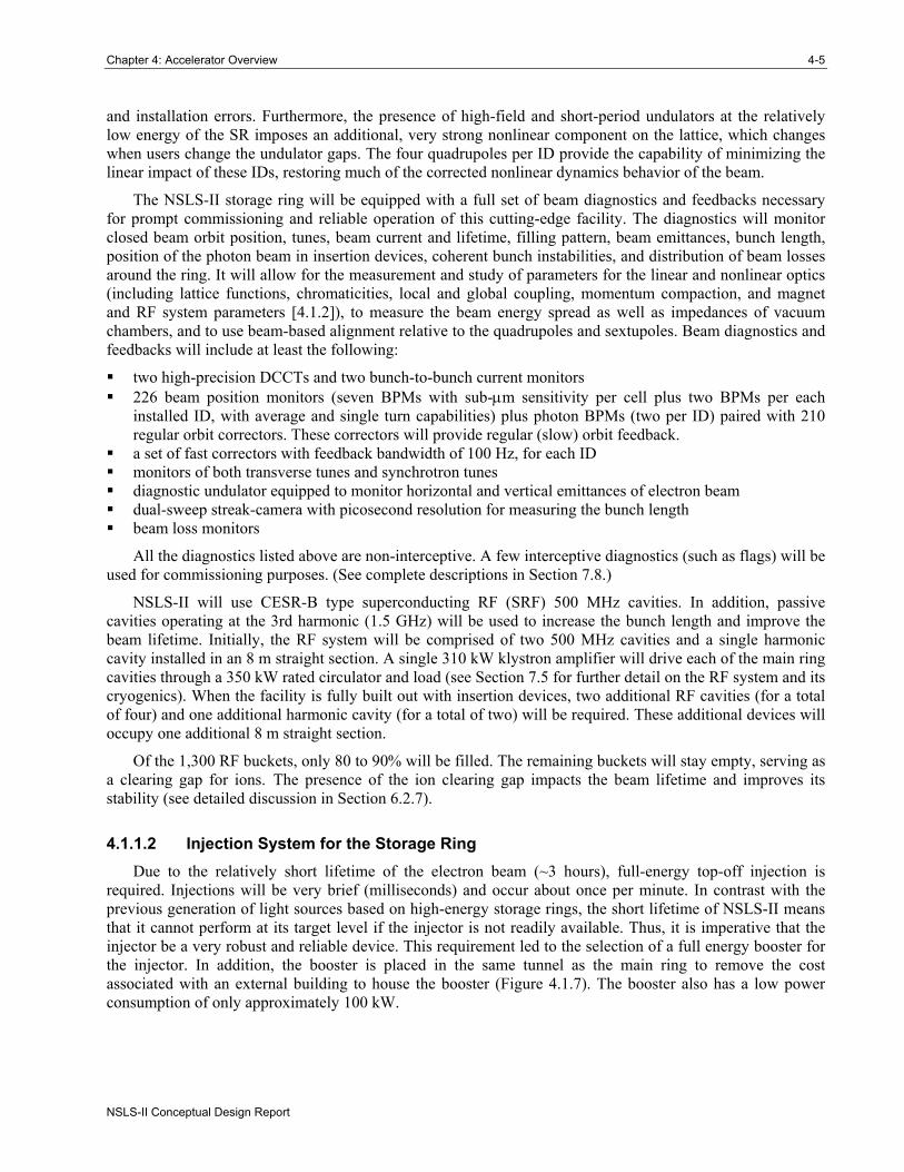
and installation errors. Furthermore, the presence of high-field and short-period undulators at the relatively low energy of the SR imposes an additional, very strong nonlinear component on the lattice, which changes when users change the undulator gaps. The four quadrupoles per ID provide the capability of minimizing the linear impact of these IDs, restoring much of the corrected nonlinear dynamics behavior of the beam.
The NSLS-II storage ring will be equipped with a full set of beam diagnostics and feedbacks necessary for prompt commissioning and reliable operation of this cutting-edge facility. The diagnostics will monitor closed beam orbit position, tunes, beam current and lifetime, filling pattern, beam emittances, bunch length, position of the photon beam in insertion devices, coherent bunch instabilities, and distribution of beam losses around the ring. It will allow for the measurement and study of parameters for the linear and nonlinear optics (including lattice functions, chromaticities, local and global coupling, momentum compaction, and magnet and RF system parameters [4.1.2]), to measure the beam energy spread as well as impedances of vacuum chambers, and to use beam-based alignment relative to the quadrupoles and sextupoles. Beam diagnostics and feedbacks will include at least the following:
two high-precision DCCTs and two bunch-to-bunch current monitors 226 beam position monitors (seven BPMs with sub-μm sensitivity per cell plus two BPMs per each
installed ID, with average and single turn capabilities) plus photon BPMs (two per ID) paired with 210 regular orbit correctors. These correctors will provide regular (slow) orbit feedback.
a set of fast correctors with feedback bandwidth of 100 Hz, for each ID monitors of both transverse tunes and synchrotron tunes diagnostic undulator equipped to monitor horizontal and vertical emittances of electron beam dual-sweep streak-camera with picosecond resolution for measuring the bunch length beam loss monitors
All the diagnostics listed above are non-interceptive. A few interceptive diagnostics (such as flags) will be used for commissioning purposes. (See complete descriptions in Section 7.8.)
NSLS-II will use CESR-B type superconducting RF (SRF) 500 MHz cavities. In addition, passive cavities operating at the 3rd harmonic (1.5 GHz) will be used to increase the bunch length and improve the beam lifetime. Initially, the RF system will be comprised of two 500 MHz cavities and a single harmonic cavity installed in an 8 m straight section. A single 310 kW klystron amplifier will drive each of the main ring cavities through a 350 kW rated circulator and load (see Section 7.5 for further detail on the RF system and its cryogenics). When the facility is fully built out with insertion devices, two additional RF cavities (for a total of four) and one additional harmonic cavity (for a total of two) will be required. These additional devices will occupy one additional 8 m straight section.
Of the 1,300 RF buckets, only 80 to 90% will be filled. The remaining buckets will stay empty, serving as a clearing gap for ions. The presence of the ion clearing gap impacts the beam lifetime and improves its stability (see detailed discussion in Section 6.2.7).
4.1.1.2 Injection System for the Storage Ring Due to the relatively short lifetime of the electron beam (~3 hours), full-energy top-off injection is
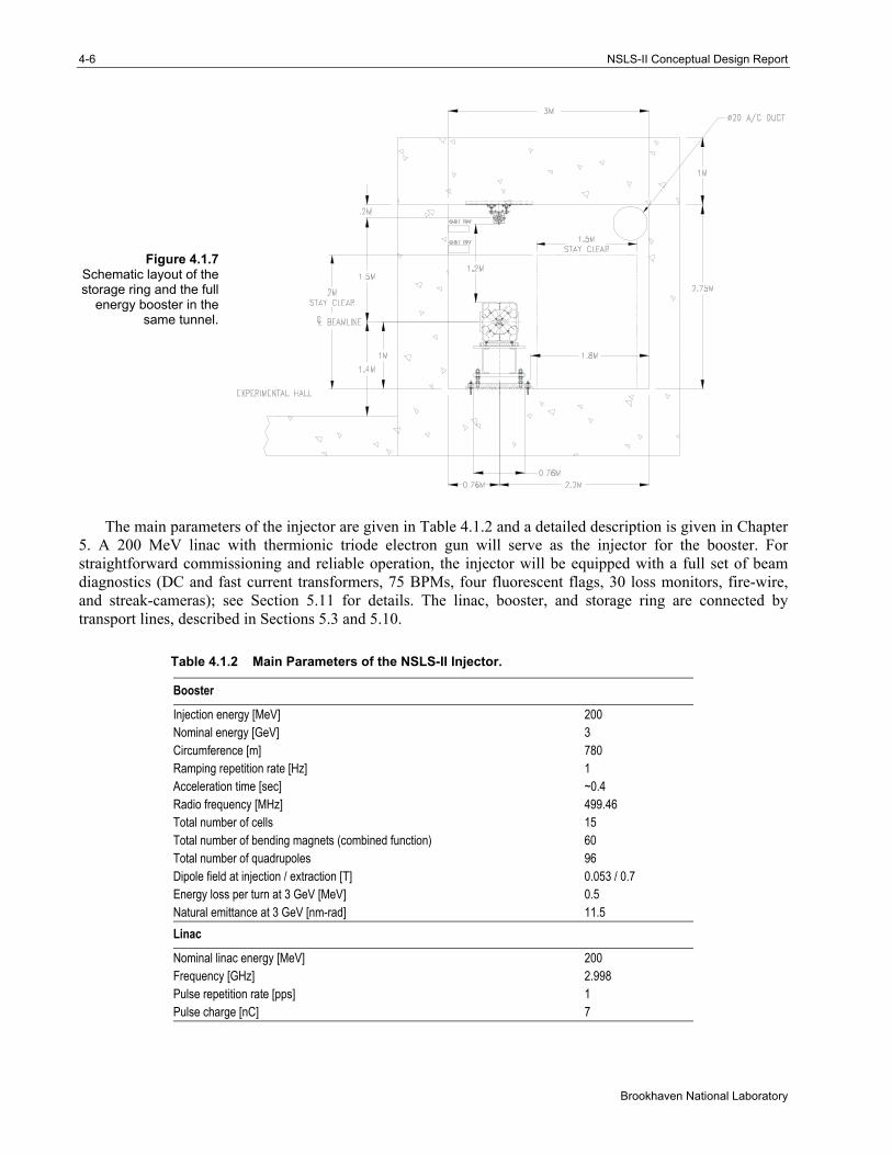
required. Injections will be very brief (milliseconds) and occur about once per minute. In contrast with the previous generation of light sources based on high-energy storage rings, the short lifetime of NSLS-II means that it cannot perform at its target level if the injector is not readily available. Thus, it is imperative that the injector be a very robust and reliable device. This requirement led to the selection of a full energy booster for the injector. In addition, the booster is placed in the same tunnel as the main ring to remove the cost associated with an external building to house the booster (Figure 4.1.7). The booster also has a low power consumption of only approximately 100 kW.
4-6 NSLS-II Conceptual Design Report
Brookhaven National Laboratory
Figure 4.1.7 Schematic layout of the storage ring and the full
energy booster in the same tunnel.
The main parameters of the injector are given in Table 4.1.2 and a detailed description is given in Chapter 5. A 200 MeV linac with thermionic triode electron gun will serve as the injector for the booster. For straightforward commissioning and reliable operation, the injector will be equipped with a full set of beam diagnostics (DC and fast current transformers, 75 BPMs, four fluorescent flags, 30 loss monitors, fire-wire, and streak-cameras); see Section 5.11 for details. The linac, booster, and storage ring are connected by transport lines, described in Sections 5.3 and 5.10.
Table 4.1.2 Main Parameters of the NSLS-II Injector.
Booster
Injection energy [MeV] 200 Nominal energy [GeV] 3 Circumference [m] 780 Ramping repetition rate [Hz] 1 Acceleration time [sec] ~0.4 Radio frequency [MHz] 499.46 Total number of cells 15 Total number of bending magnets (combined function) 60 Total number of quadrupoles 96 Dipole field at injection / extraction [T] 0.053 / 0.7 Energy loss per turn at 3 GeV [MeV] 0.5 Natural emittance at 3 GeV [nm-rad] 11.5 Linac
Nominal linac energy [MeV] 200 Frequency [GHz] 2.998 Pulse repetition rate [pps] 1 Pulse charge [nC] 7
Chapter 4: Accelerator Overview 4-7
NSLS-II Conceptual Design Report
The booster RF system (Section 5.8) will be based on a five-cell “PETRA” (room temperature, copper) cavity that will provide 1 MV accelerating voltage, which is sufficient for the acceleration and required energy acceptance. An 80 kW IOT transmitter will be used to provide the 50 kW of power required for the cavity.
4.1.1.3 Photon Sources The NSLS-II storage ring has 27 straight sections available for insertion devices (one 8 m straight section
will be used for the injection and two for the RF system). An 8 m straight section can also accommodate two short undulators whose radiation is separated by a local angular bump (so-called canted undulators). NSLS-II will host a variety of different types of undulators and wigglers that will generate high brightness and high flux beams of hard and soft x-rays. A full description of these IDs and their performance, together with that of the bending magnets, is given in Chapter 8. The storage ring lattice is designed to withstand the influence of a complete set of insertion devices set to arbitrary gap (field) values in the fully developed facility (see Section 6.1.2.8).
NSLS-II will use damping wigglers (see Section 4.2) for two purposes [4.1.3]:
1. to reduce horizontal beam emittance to the desired level while minimizing the number of cells of the lattice and thus the circumference (and cost) of the storage ring
2. to serve as broadband sources of very bright and high flux x-rays superior to conventional bend-magnet sources
4.1.1.4 Mechanical Design and Magnets Many of the mechanical designs for NSLS-II are now conventional technology for third-generation light
sources. Most of the NSLS-II storage ring uses extruded aluminum vacuum chamber with short (about 15 cm) stainless steel inserts for fast feedback orbit correctors. This vacuum chamber provides for in-situ bakeout to 130°C using pressurized hot water circulated within the cooling water channel of the Al profile. Synchrotron radiation is either extracted to a user beamline or intercepted by a localized water-cooled copper absorber (see Section 7.4). All bellows in the storage ring vacuum chamber will be RF shielded to provide low impedance and low losses. The most complex are the vacuum chambers for the insertion devices, especially those for in-vacuum undulators with flexible transitions. These devices are described in Section 7.4.3. Vacuum pressure of 1×10⁻⁹ Torr will be provided by 240 ion vacuum pumps, 180 titanium sublimation pumps, and about 250 NEG pumps distributed around the ring, IDs, and front ends. The ring vacuum system will have 90 gate valves. The pressure and the residual gas content in the storage ring will be monitored by 270 ion gauges and by 104 residual gas analyzers.
Stainless steel will be used for the booster vacuum chamber (Section 5.7), transport lines, and linac. The low ramp-rate of the booster allows us to use simple elliptical vacuum chambers. A suite of vacuum pumps, vacuum gauges, and RGAs will be used to support and monitor vacuum at the 10-7 Torr level.
The main parameters of the magnets for the booster and storage ring are discussed in detail in Sections 5.6 and 7.1, respectively. A number of pulsed elements (kickers and septa) are also used in NSLS-II, as described in Sections 5.9 and 7.6.2.2.
Among the most challenging requirements are those associated with the precise alignment of magnetic elements in the storage ring. Another challenge is the design of the girder system, which must be as rigid as possible to reduce vibration of the elements that results in low-frequency noise in the position and angle data from the x-ray beams. The solutions for these challenging problems are described in Section 7.2.
4-8 NSLS-II Conceptual Design Report
Brookhaven National Laboratory
4.2 Optimization of the NSLS-II Design
The pre-conceptual design of NSLS-II [4.2.1] was based on 24 triple-bend achromatic cells (TBA24) with a circumference of 630 m. Further extensive studies [4.2.2] demonstrated that this lattice, with a horizontal emittance of 1.5 nm-rad, was not robust. The dynamic aperture for this lattice collapsed in the presence of realistic errors. Further studies explored possibilities of various lattices (DBA vs. TBA), radii of curvature, and circumferences, as well as damping wigglers.
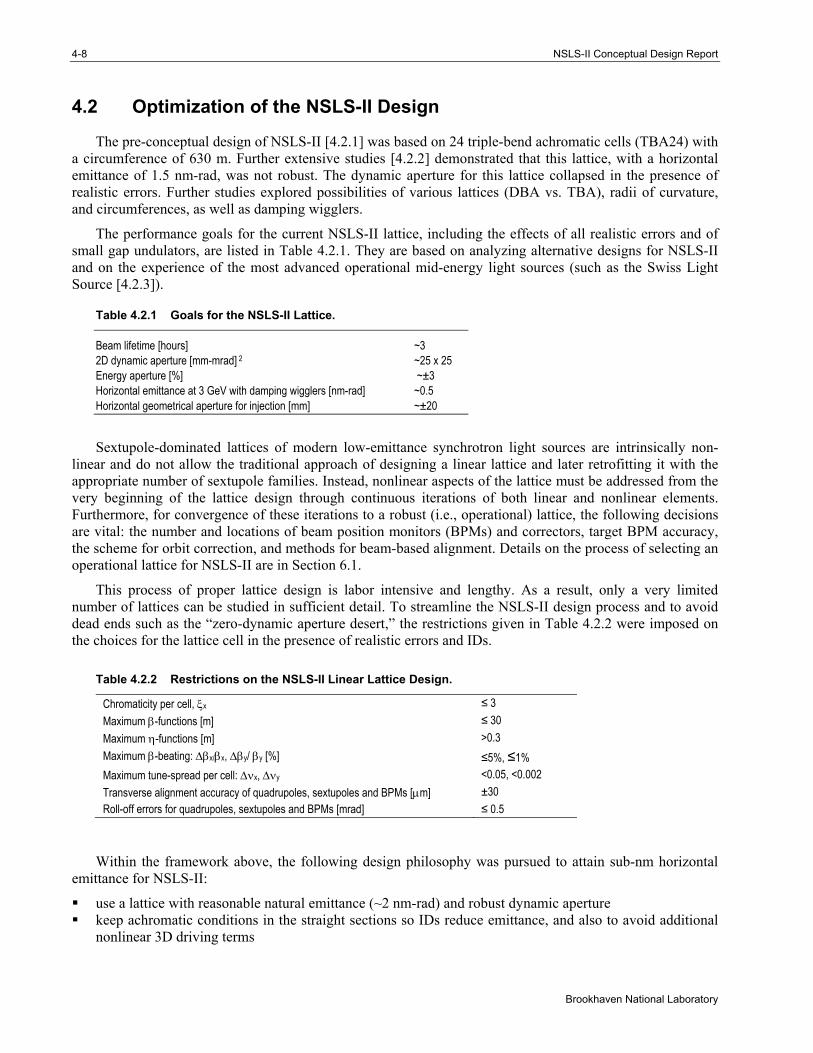
The performance goals for the current NSLS-II lattice, including the effects of all realistic errors and of small gap undulators, are listed in Table 4.2.1. They are based on analyzing alternative designs for NSLS-II and on the experience of the most advanced operational mid-energy light sources (such as the Swiss Light Source [4.2.3]).
Table 4.2.1 Goals for the NSLS-II Lattice.
Beam lifetime [hours] ~3 2D dynamic aperture [mm-mrad] 2 ~25 x 25 Energy aperture [%] ~±3 Horizontal emittance at 3 GeV with damping wigglers [nm-rad] ~0.5 Horizontal geometrical aperture for injection [mm] ~±20
Sextupole-dominated lattices of modern low-emittance synchrotron light sources are intrinsically non-linear and do not allow the traditional approach of designing a linear lattice and later retrofitting it with the appropriate number of sextupole families. Instead, nonlinear aspects of the lattice must be addressed from the very beginning of the lattice design through continuous iterations of both linear and nonlinear elements. Furthermore, for convergence of these iterations to a robust (i.e., operational) lattice, the following decisions are vital: the number and locations of beam position monitors (BPMs) and correctors, target BPM accuracy, the scheme for orbit correction, and methods for beam-based alignment. Details on the process of selecting an operational lattice for NSLS-II are in Section 6.1.
This process of proper lattice design is labor intensive and lengthy. As a result, only a very limited number of lattices can be studied in sufficient detail. To streamline the NSLS-II design process and to avoid dead ends such as the “zero-dynamic aperture desert,” the restrictions given in Table 4.2.2 were imposed on the choices for the lattice cell in the presence of realistic errors and IDs.
Table 4.2.2 Restrictions on the NSLS-II Linear Lattice Design.
Chromaticity per cell, ξx ≤ 3 Maximum β-functions [m] ≤ 30 Maximum η-functions [m] >0.3 Maximum β-beating: Δβx/βx, Δβy/ βy [%] ≤5%, ≤1% Maximum tune-spread per cell: Δνx, Δνy <0.05, <0.002 Transverse alignment accuracy of quadrupoles, sextupoles and BPMs [μm] ±30 Roll-off errors for quadrupoles, sextupoles and BPMs [mrad] ≤ 0.5
Within the framework above, the following design philosophy was pursued to attain sub-nm horizontal emittance for NSLS-II:
use a lattice with reasonable natural emittance (~2 nm-rad) and robust dynamic aperture keep achromatic conditions in the straight sections so IDs reduce emittance, and also to avoid additional
nonlinear 3D driving terms
Chapter 4: Accelerator Overview 4-9
NSLS-II Conceptual Design Report
use damping wigglers to reduce emittance limit total losses of synchrotron radiation to 1 to 2 MeV per turn to limit electrical power consumption increase bending radius to maximize impact of damping wigglers while keeping emittance under control monitor the cost
Using a larger radius for the bending magnets causes a modest increase in the ring’s circumference and some increase in the maximum dispersion, resulting in reduced sextupole strengths. Our studies showed that it is possible to keep the bare emittance under control while increasing the bending radius of the dipole magnets. Increasing the bending radius reduces the dipole field ( Bo = pc /eρo) and (in the case of the same coil cross-section) reduces the power consumption.
The approach of using damping wigglers to achieve low horizontal emittance has been used previously in accelerators designed for high energy physics, but it has not been widely used for light source designs. Usually the use of damping wigglers is associated with large synchrotron radiation losses and large consumption of RF power. This is not the case for NSLS-II – the use of a large bending radius proportionately reduces the radiation losses from both the bending magnets (Ubends) and the damping wigglers. This is a unique feature of the NSLS-II design. The emittance for a given total loss per turn from synchrotron radiation (Utotal), i.e., for a given RF power, decreases with the increase of the radius of curvature:
[ ] [ ]
[ ]][
17.7)3(@
][ 5.88 ;
4
mMeVGeVU
mGeVEkeVU
UU
obends
obends
total
bendsbarenat
ρ
ρεε
≅
⋅≅⋅≅, (4.2-1)
where εbare is the emittance of the bare lattice (without wigglers) and εnat is the natural emittance in the presence of damping wigglers [4.2.4].
This approach to emittance control is straightforward and has a rather modest effect on the vertical dynamic aperture (see Section 6.1). The fact that the damping wigglers at NSLS-II will be also very bright, high-intensity sources of broadband x-rays makes this approach even more attractive.
Using this design approach, two promising lattices, the TBA24 (bending radius of 18 m) and the DBA32 (bending radius of 15.3 m), emerged in the early stages of the conceptual design development. Both lattices at the time of consideration had circumference ~750 meters with bare natural horizontal emittance between 1.8 and 2 nm-rad. Both could go well below 1 nm-rad with the use of damping wigglers and clearly indicated a potential for robustness.
A key advantage of lattices based on a DBA cell compared to a TBA cell is that, for lattices with comparable bare emittance, the DBA cell allows significantly more straight sections for user IDs while having a similar number of magnets and circumference. Lattices based on a DBA cell are thus preferred, and further studies were focused on selecting the optimum number of DBA cells.
Table 4.2.3 shows the key parameters used in selecting the optimum size DBA lattice. All lattices considered had a super-period of two cells, with alternating straight section lengths of 8 m and 5 m, and a bend magnet radius of 25 m (the optimum choice of bend magnet radius is discussed in the next section). A straight section length of 8 m is required in order to inject in a single straight, as well as to accommodate two RF cavities and one harmonic cavity in a single straight. The second straight section length of 5 m was chosen as a compromise between having longer IDs and minimizing the storage ring circumference. Shorter straights are also conducive to having smaller beta functions, and hence smaller beam sizes, as discussed in Chapter 6. Achieving very small beam sizes is especially beneficial in enabling the photon beam to be focused down to a 1 nm spot size, as discussed in Chapter 11. As discussed generally in the next section, and shown in Table 6.1.3 and Figure 6.1.3 for the choice of a DBA30 lattice with 25 m bend magnet radius, eight 7 m long damping wigglers are sufficient to achieve nearly the full emittance reduction that can be achieved from
4-10 NSLS-II Conceptual Design Report
Brookhaven National Laboratory
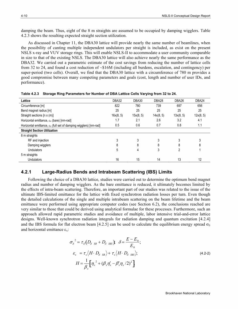
damping the beam. Thus, eight of the 8 m straights are assumed to be occupied by damping wigglers. Table 4.2.3 shows the resulting expected straight section utilization.
As discussed in Chapter 11, the DBA30 lattice will provide nearly the same number of beamlines, when the possibility of canting multiple independent undulators per straight is included, as exist on the present NSLS x-ray and VUV storage rings. This will enable NSLS-II to accommodate a user community comparable in size to that of the existing NSLS. The DBA30 lattice will also achieve nearly the same performance as the DBA32. We carried out a parametric estimate of the cost savings from reducing the number of lattice cells from 32 to 24, and found a cost reduction of ~$16M (including all burdens, escalation, and contingency) per super-period (two cells). Overall, we find that the DBA30 lattice with a circumference of 780 m provides a good compromise between many competing parameters and goals (cost, length and number of user IDs, and performance).
Table 4.2.3 Storage Ring Parameters for Number of DBA Lattice Cells Varying from 32 to 24.
Lattice DBA32 DBA30 DBA28 DBA26 DBA24 Circumference [m] 822 780 739 697 656 Bend magnet radius [m] 25 25 25 25 25 Straight sections [n x (m)] 16x(8, 5) 15x(8, 5) 14x(8, 5) 13x(8, 5) 12x(8, 5) Horizontal emittance, εx (bare) [nm-rad] 1.7 2.1 2.6 3.2 4.1 Horizontal emittance, εx (full set of damping wigglers) [nm-rad] 0.5 0.6 0.7 0.8 1.1 Straight Section Utilization 8 m straights RF and injection 3 3 3 3 3 Damping wigglers 8 8 8 8 8 Undulators 5 4 3 2 1 5 m straights Undulators 16 15 14 13 12
4.2.1 Large-Radius Bends and Intrabeam Scattering (IBS) Limits Following the choice of a DBA30 lattice, studies were carried out to determine the optimum bend magnet
radius and number of damping wigglers. As the bare emittance is reduced, it ultimately becomes limited by the effects of intra-beam scattering. Therefore, an important part of our studies was related to the issue of the ultimate IBS-limited emittance for the lattice with fixed synchrotron radiation losses per turn. Even though the detailed calculations of the single and multiple intrabeam scattering on the beam lifetime and the beam emittance were performed using appropriate computer codes (see Section 6.2), the conclusions reached are very similar to those that could be derived using analytical formulae for these processes. Furthermore, such an approach allowed rapid parametric studies and avoidance of multiple, labor intensive trial-and-error lattice designs. Well-known synchrotron radiation integrals for radiation damping and quantum excitation [4.2.4] and the IBS formula for flat electron beam [4.2.5] can be used to calculate the equilibrium energy spread σδ and horizontal emittance εx:
σδ2 = τ E Dδ SR + Dδ IBS( ); δ =
E − E0
E0
;
εx = τ x H ⋅ Dδ SR + τ x H ⋅ Dδ IBS ;
H =1βx
ηx2 + (βx ′ η x − ′ β xηx /2)2[ ],
(4.2-2)
Chapter 4: Accelerator Overview 4-11
NSLS-II Conceptual Design Report
where Eo is the energy of the electron beam, E is the energy of individual electrons, and τE and τx are the damping time of energy (synchrotron) oscillations and horizontal betatron oscillations, respectively. Dδ SR and Dδ IBS are relative energy diffusion coefficients caused by quantum fluctuations of synchrotron radiation (i.e., causing so-called natural emittance) and by the intrabeam scattering, respectively. The H-function is the well-known connection between emittance growth and the energy diffusion coefficients.
The energy diffusion induced by IBS can be expressed in the following terms:
Dδ IBS =Nere
2c25πγ 3εx εyβy s( )σ s
f χm s( )( ); f χm( )=dχχχm
∞
∫ ln χχm
⎛
⎝ ⎜
⎞
⎠ ⎟ e−χ ;
(4.2-3)
χm =rem
2c 4
bmaxΔEacc2 ; bmax ≅ n−1/ 3,
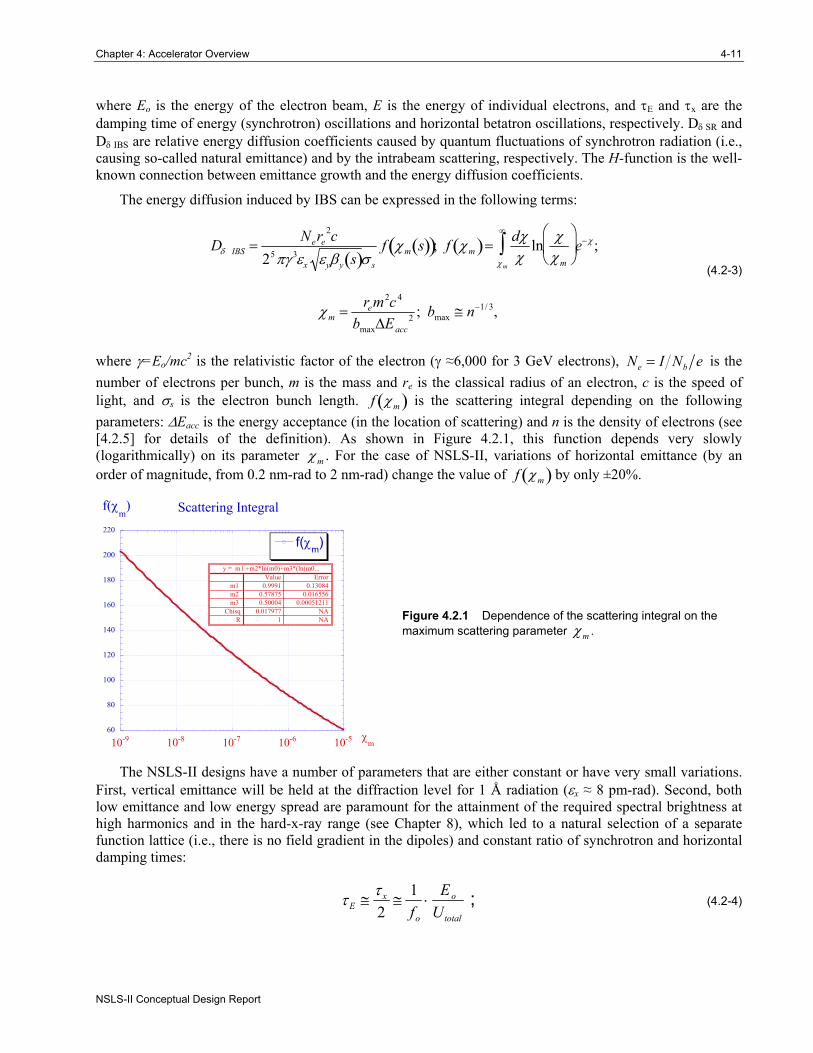
where γ=Eo/mc2 is the relativistic factor of the electron (γ ≈6,000 for 3 GeV electrons), e bN I N e= is the number of electrons per bunch, m is the mass and re is the classical radius of an electron, c is the speed of light, and σs is the electron bunch length. f χm( ) is the scattering integral depending on the following parameters: ΔEacc is the energy acceptance (in the location of scattering) and n is the density of electrons (see [4.2.5] for details of the definition). As shown in Figure 4.2.1, this function depends very slowly (logarithmically) on its parameter χm . For the case of NSLS-II, variations of horizontal emittance (by an order of magnitude, from 0.2 nm-rad to 2 nm-rad) change the value of f χm( ) by only ±20%.
60
80
100
120
140
160
180
200
220
10-9 10-8 10-7 10-6 10-5
Scattering Integral
f(χm)
f(χm
)
χm
y = m1 +m2*ln(m0)+m3*(ln(m0...ErrorValue
0.130840.9991m1 0.0165560.57875m2
0.000512110.50004m3 NA0.017977ChisqNA1R Figure 4.2.1 Dependence of the scattering integral on the
maximum scattering parameter χm .
The NSLS-II designs have a number of parameters that are either constant or have very small variations. First, vertical emittance will be held at the diffraction level for 1 Å radiation (εx ≈ 8 pm-rad). Second, both low emittance and low energy spread are paramount for the attainment of the required spectral brightness at high harmonics and in the hard-x-ray range (see Chapter 8), which led to a natural selection of a separate function lattice (i.e., there is no field gradient in the dipoles) and constant ratio of synchrotron and horizontal damping times:
τ E ≅τ x
2≅
1fo
⋅Eo
Utotal
; (4.2-4)
4-12 NSLS-II Conceptual Design Report
Brookhaven National Laboratory
where To=1/fo is the revolution time of electrons around the ring. Thus the damping time is simply proportional to the ring circumference and to the ratio between the beam energy and total losses on synchrotron radiation Eo/Utotal. Third, the bunch length in NSLS-II will be kept about constant (between 3 mm and 4.5 mm,) by various means, including its lengthening by harmonics cavity (see Section 6.2.7).
Equations (4.2-2) and (4.2-3) can be solved with respect to the natural emittance (εnat = τ x H ⋅ Dδ SR ; i.e., the beam emittance in the absence of the IBS) using weak dependence of the scattering integral on the beam emittance:
εx total ≅εnat
21+ 1+
4εIBS2
εnat2
⎛
⎝ ⎜ ⎜
⎞
⎠ ⎟ ⎟ , (4.2-5)
where εIBS is the minimum emittance that can be achieved in a given lattice for a given current per bunch Ib=eNefo:
( )( )( )
2
5 3 ( )2
mx e eIBS
s y y
f sN r c H ss
χτεπγ σ ε β
=
. (4.2-6)
The expression for εIBS (Eq. 4.2-5) can be easily evaluated for any given lattice and bunch parameters, and it naturally has very weak (square root) dependence on the bunch length, bunch current, and damping time, and even weaker (4th power root) dependence on vertical emittance. Overall, this number is a good measure of the ultimate emittance one can approach with realistic beams. For all realistic TBA24 and DBA24 through DBA32 lattices and related beam parameters under consideration (and maximum total losses limited to 1 MeV per turn), the value of εIBS was between 0.2 nm-rad and 0.25 nm-rad, thus setting the natural limit for attainable emittance. Naturally, increasing the power losses by a factor of two to 2 MeV per turn would further reduce εIBS by 2 .
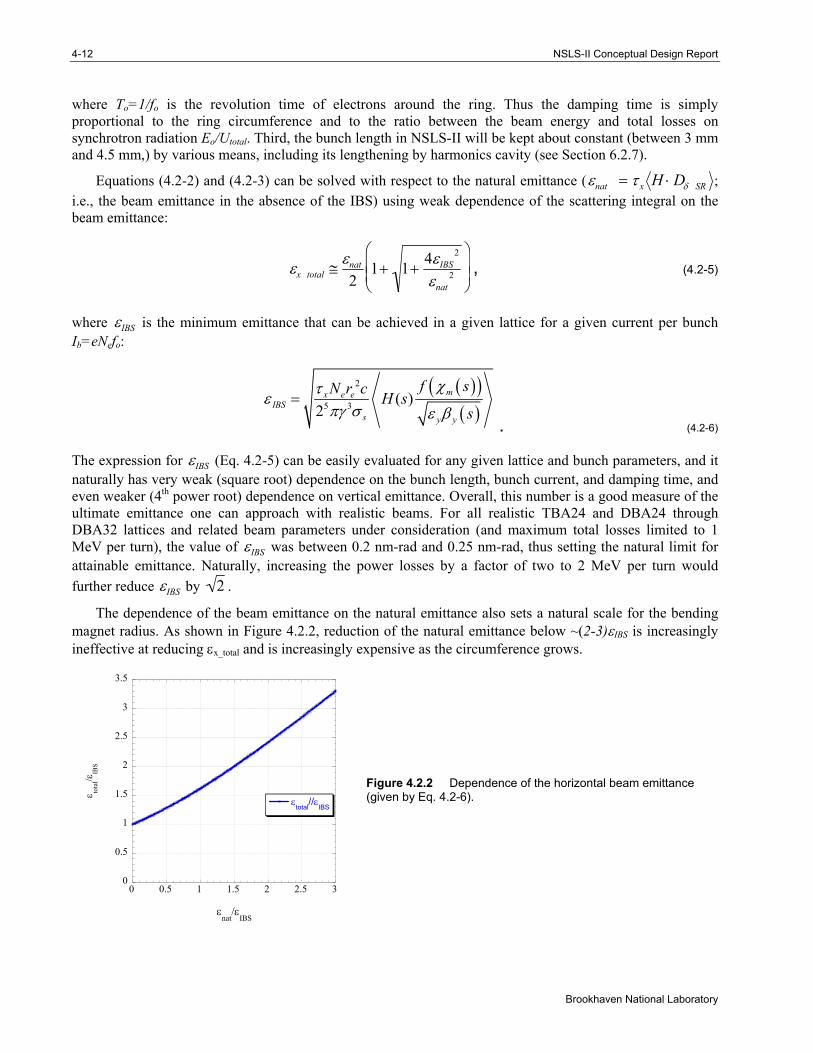
The dependence of the beam emittance on the natural emittance also sets a natural scale for the bending magnet radius. As shown in Figure 4.2.2, reduction of the natural emittance below ~(2-3)εIBS is increasingly ineffective at reducing εx_total and is increasingly expensive as the circumference grows.
0
0.5
1
1.5
2
2.5
3
3.5
0 0.5 1 1.5 2 2.5 3
εtotal//εIBS
ε tota
l/εIB
S
εnat
/εIBS
Figure 4.2.2 Dependence of the horizontal beam emittance (given by Eq. 4.2-6).
Chapter 4: Accelerator Overview 4-13
NSLS-II Conceptual Design Report
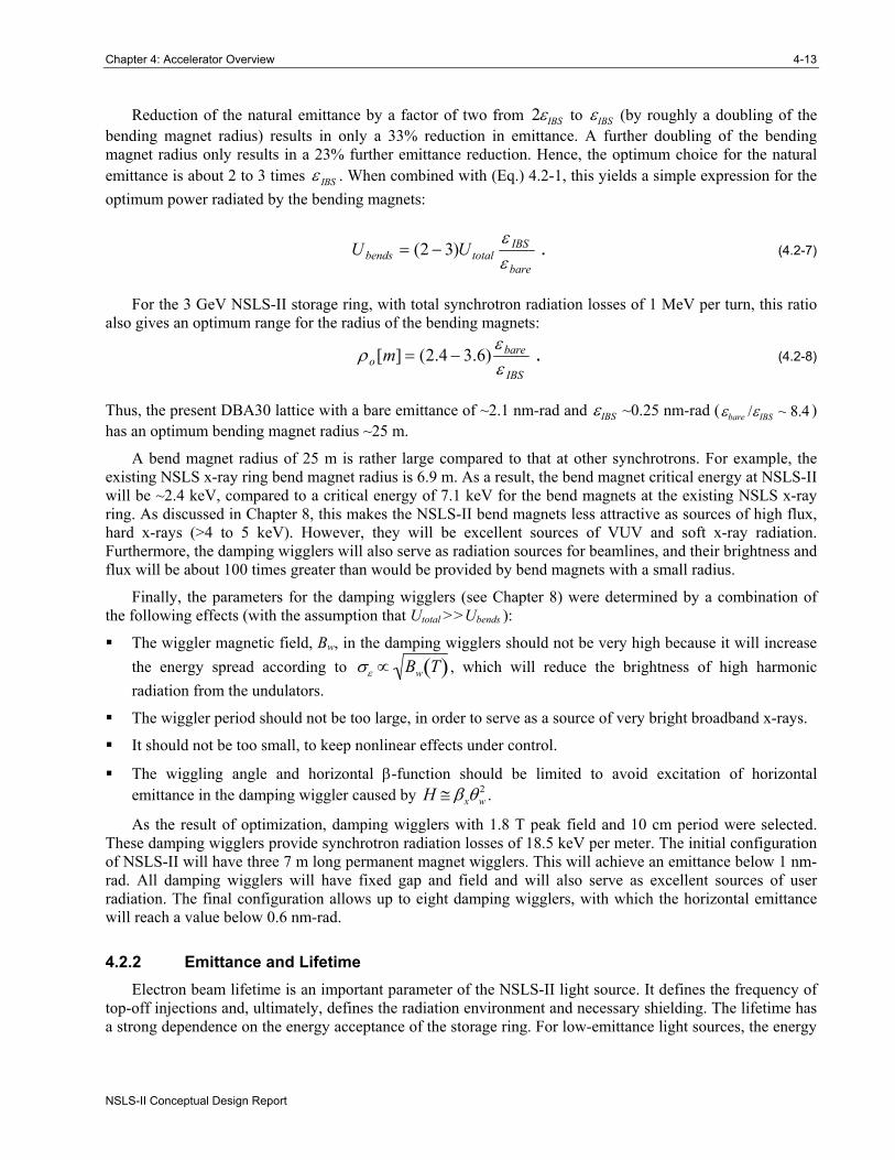
Reduction of the natural emittance by a factor of two from 2εIBS to εIBS (by roughly a doubling of the bending magnet radius) results in only a 33% reduction in emittance. A further doubling of the bending magnet radius only results in a 23% further emittance reduction. Hence, the optimum choice for the natural emittance is about 2 to 3 times IBSε . When combined with (Eq.) 4.2-1, this yields a simple expression for the optimum power radiated by the bending magnets:
bare
IBStotalbends UU
εε
)32( −= . (4.2-7)
For the 3 GeV NSLS-II storage ring, with total synchrotron radiation losses of 1 MeV per turn, this ratio also gives an optimum range for the radius of the bending magnets:
IBS
bareo m
εε
ρ )6.34.2(][ −= . (4.2-8)
Thus, the present DBA30 lattice with a bare emittance of ~2.1 nm-rad and εIBS ~0.25 nm-rad (εbare /εIBS ~ 8.4 ) has an optimum bending magnet radius ~25 m.
A bend magnet radius of 25 m is rather large compared to that at other synchrotrons. For example, the existing NSLS x-ray ring bend magnet radius is 6.9 m. As a result, the bend magnet critical energy at NSLS-II will be ~2.4 keV, compared to a critical energy of 7.1 keV for the bend magnets at the existing NSLS x-ray ring. As discussed in Chapter 8, this makes the NSLS-II bend magnets less attractive as sources of high flux, hard x-rays (>4 to 5 keV). However, they will be excellent sources of VUV and soft x-ray radiation. Furthermore, the damping wigglers will also serve as radiation sources for beamlines, and their brightness and flux will be about 100 times greater than would be provided by bend magnets with a small radius.
Finally, the parameters for the damping wigglers (see Chapter 8) were determined by a combination of the following effects (with the assumption that Utotal >>Ubends ):
The wiggler magnetic field, Bw, in the damping wigglers should not be very high because it will increase the energy spread according to σε ∝ Bw T( ) , which will reduce the brightness of high harmonic radiation from the undulators.
The wiggler period should not be too large, in order to serve as a source of very bright broadband x-rays.
It should not be too small, to keep nonlinear effects under control.
The wiggling angle and horizontal β-function should be limited to avoid excitation of horizontal emittance in the damping wiggler caused by H ≅ βxθw
2 .
As the result of optimization, damping wigglers with 1.8 T peak field and 10 cm period were selected. These damping wigglers provide synchrotron radiation losses of 18.5 keV per meter. The initial configuration of NSLS-II will have three 7 m long permanent magnet wigglers. This will achieve an emittance below 1 nm-rad. All damping wigglers will have fixed gap and field and will also serve as excellent sources of user radiation. The final configuration allows up to eight damping wigglers, with which the horizontal emittance will reach a value below 0.6 nm-rad.
4.2.2 Emittance and Lifetime Electron beam lifetime is an important parameter of the NSLS-II light source. It defines the frequency of
top-off injections and, ultimately, defines the radiation environment and necessary shielding. The lifetime has a strong dependence on the energy acceptance of the storage ring. For low-emittance light sources, the energy
4-14 NSLS-II Conceptual Design Report
Brookhaven National Laboratory
acceptance depends not only on the linear compaction factor α1 (in NSLS-II, higher order compaction factors are not important, α1 α2 ≈ 3.7 ×10⁻⁴ 4.1×10−4 = 92%) and the parameters of the RF system (harmonic, voltage, synchronous phase), but also may depend on nonlinear coupling and the vertical gap in IDs.
Here we will focus on two unusual phenomena in the lifetime dependences for the NSLS-II storage ring, and their consequences:
For a given energy acceptance, the beam lifetime depends very weakly on the value of the horizontal emittance (within the range from 0.2 nm-rad to 2 nm-rad).
Lifetime dependence on the energy acceptance is approaching the fourth power of the latter.
Conventional wisdom says that lowering the beam emittance in an electron storage ring leads to a proportional reduction of the lifetime. This conclusion can be drawn from the following formula [4.2.5]:
1τTouschek
=Nere
2c8π ⋅ σ xσ yσ s ⋅ γ 2 ⋅ δacc
3 D ξ( ); ξ =δacc
γσθ
⎛
⎝ ⎜
⎞
⎠ ⎟
2
;
D ξ( )= ξ −32
e−ξ +ξ2
lnu ⋅ e−u
udu
ξ
∞
∫ + 12
3ξ −ξ lnξ + 2( ) e−u
udu
ξ
∞
∫⎧ ⎨ ⎪
⎩ ⎪
⎫ ⎬ ⎪
⎭ ⎪
(4.2-9)
where δacc = ΔEacc / Eo is the relative energy acceptance, σθ is the transverse angular spread (dominated by horizontal oscillation for the NSLS-II case), σ x,y = βx,yεx,y are the transverse RMS beam sizes, and D ξ( ) is the scattering integral causing loss of the electrons.
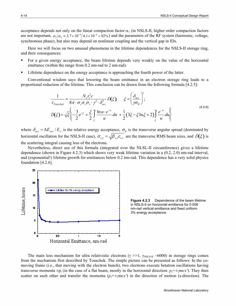
Nevertheless, direct use of this formula (integrated over the NLSL-II circumference) gives a lifetime dependence (shown in Figure 4.2.3) which shows very weak lifetime variation in a (0.2, 2.0) nm-rad interval, and (exponential!) lifetime growth for emittances below 0.2 nm-rad. This dependence has a very solid physics foundation [4.2.6].
Figure 4.2.3 Dependence of the beam lifetime in NSLS-II on horizontal emittance for 0.008 nm-rad vertical emittance and fixed uniform 3% energy acceptance.
The main loss mechanism for ultra relativistic electrons (γ >>1, γNSLS-II ~6000) in storage rings comes from the mechanism first described by Touschek. The simple picture can be presented as follows: In the co-moving frame (i.e., that moving with the electron bunch), two electrons execute betatron oscillations having transverse momenta ±pt (in the case of a flat beam, mostly in the horizontal direction: px=±γmcx′). They then scatter on each other and transfer the momenta (ps=±γmcx′) in the direction of motion (s-direction). The
Chapter 4: Accelerator Overview 4-15
NSLS-II Conceptual Design Report
Lorentz transformation into the laboratory frame gives a relativistic boost to ps momenta by a factor of γ and generates an energy deviation of ΔE ≈ ±γ2mcx′. If the energies of the scattered electrons are outside the energy acceptance (γ2mcx′ >±ΔEacc ), then the electrons may get lost. For most storage rings, the angular RMS spread of the electrons,
σθ (s) = εx 1+ αx2(s)( )/βx (s) + εy 1+ α y
2(s)( )/βy (s) + ′ η 2(s)σδ2 , (4.2-10)
is sufficient for such a process to occur (note that σθ is a function of azimuth s). But for storage rings with extremely low emittances (in the NSLS-II case, sub-angstrom emittances), only the far tails of the electron distribution f θ( )= exp −θ 2 /2σθ
2( )/ 2πσθ can cause such processes, and the lifetime of such beams
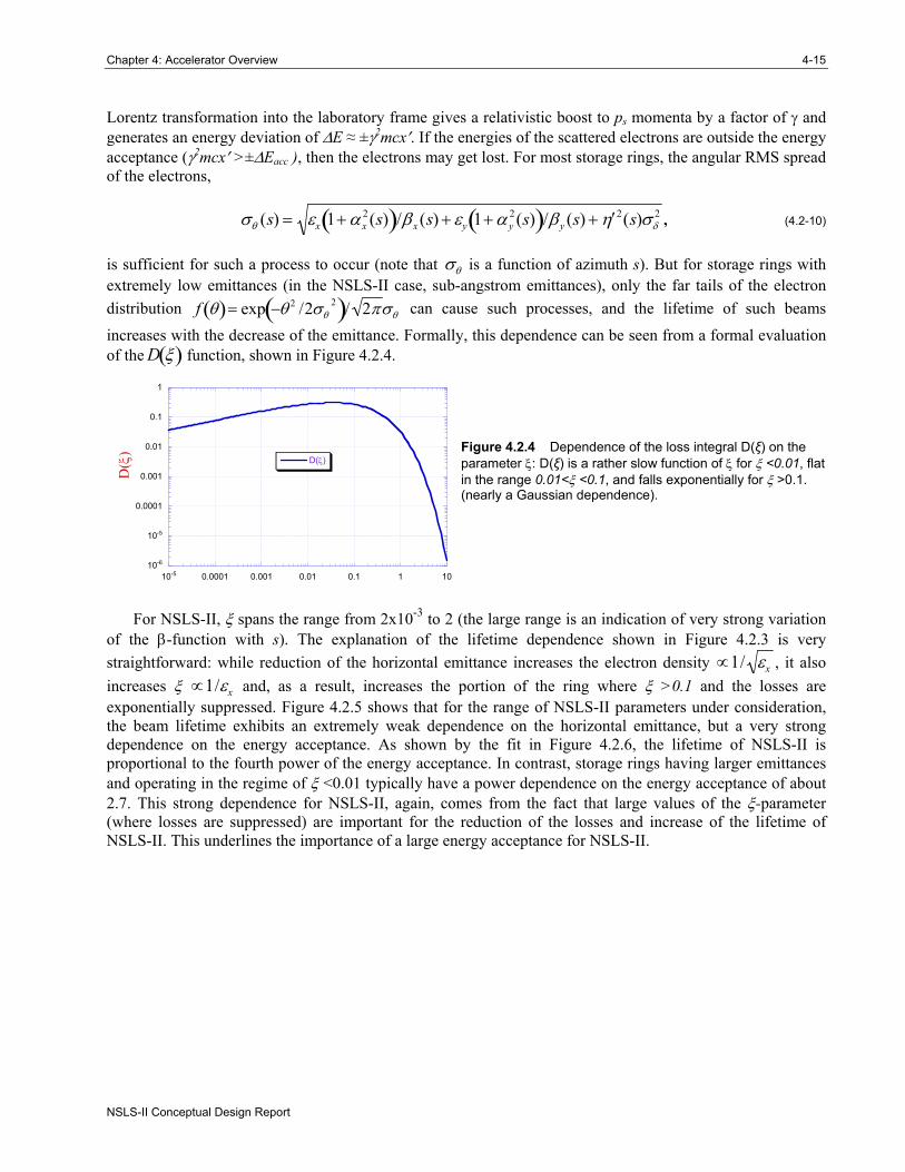
increases with the decrease of the emittance. Formally, this dependence can be seen from a formal evaluation of the D ξ( ) function, shown in Figure 4.2.4.
10-6
10-5
0.0001
0.001
0.01
0.1
1
10-5 0.0001 0.001 0.01 0.1 1 10
D(ξ)
D(ξ
)
Figure 4.2.4 Dependence of the loss integral D(ξ) on the parameter ξ: D(ξ) is a rather slow function of ξ for ξ <0.01, flat in the range 0.01<ξ <0.1, and falls exponentially for ξ >0.1. (nearly a Gaussian dependence).
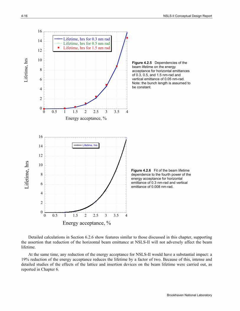
For NSLS-II, ξ spans the range from 2x10⁻³ to 2 (the large range is an indication of very strong variation of the β-function with s). The explanation of the lifetime dependence shown in Figure 4.2.3 is very straightforward: while reduction of the horizontal emittance increases the electron density ∝1/ εx , it also increases ξ ∝1/εx and, as a result, increases the portion of the ring where ξ >0.1 and the losses are exponentially suppressed. Figure 4.2.5 shows that for the range of NSLS-II parameters under consideration, the beam lifetime exhibits an extremely weak dependence on the horizontal emittance, but a very strong dependence on the energy acceptance. As shown by the fit in Figure 4.2.6, the lifetime of NSLS-II is proportional to the fourth power of the energy acceptance. In contrast, storage rings having larger emittances and operating in the regime of ξ <0.01 typically have a power dependence on the energy acceptance of about 2.7. This strong dependence for NSLS-II, again, comes from the fact that large values of the ξ-parameter (where losses are suppressed) are important for the reduction of the losses and increase of the lifetime of NSLS-II. This underlines the importance of a large energy acceptance for NSLS-II.
4-16 NSLS-II Conceptual Design Report
Brookhaven National Laboratory
Figure 4.2.5 Dependencies of the beam lifetime on the energy acceptance for horizontal emittances of 0.3, 0.5, and 1.5 nm-rad and vertical emittance of 0.05 nm-rad. Note: the bunch length is assumed to be constant.
Figure 4.2.6 Fit of the beam lifetime dependence to the fourth power of the energy acceptance for horizontal emittance of 0.3 nm-rad and vertical emittance of 0.008 nm-rad.
Detailed calculations in Section 6.2.6 show features similar to those discussed in this chapter, supporting the assertion that reduction of the horizontal beam emittance at NSLS-II will not adversely affect the beam lifetime.
At the same time, any reduction of the energy acceptance for NSLS-II would have a substantial impact: a 19% reduction of the energy acceptance reduces the lifetime by a factor of two. Because of this, intense and detailed studies of the effects of the lattice and insertion devices on the beam lifetime were carried out, as reported in Chapter 6.
0
2
4
6
8
10
12
14
16
0 0.5 1 1.5 2 2.5 3 3.5 4
Lifetime, hrs for 0.3 nm radLifetime, hrs for 0.5 nm radLifetime, hrs for 1.5 nm rad
Life
time,
hrs
Energy acceptance, %
0
2
4
6
8
10
12
14
16
0 0.5 1 1.5 2 2.5 3 3.5 4
Lifetime, hrs
Life
time,
hrs
Energy acceptance, %
Chapter 4: Accelerator Overview 4-17
NSLS-II Conceptual Design Report
4.2.3 Collective Effects Collective effects, described in detail in Section 6.2, have two distinct subgroups: instabilities and effect
on the beam parameters (IBS and lifetime). We touched on the latter in the previous section. In this section, issues related to beam instabilities will be briefly reviewed.
The studies of beam instabilities were based both on well-established theoretical estimations as well as on detailed calculations of specific impedances using the code GdfidL for the most convoluted structures (such as RF cavities and ID transitions). GdfidL was also used intensively for calculating the impedance budget for the ring with resulting longitudinal impedance values of (Z/n)o ~0.4 Ω.
The impedance model was used for estimating instability thresholds or their growth rate for the following: CESR-B SRF cavity, 720 m of Al vacuum chamber with ±12.5 mm vertical gap, 60 meters of copper shielding for in-vacuum undulators with gap of ±2.5 mm, and transverse (1 MΩ/m; Q = 1, 30 GHz) and longitudinal (Rs = 30 kΩ, Q = 1, Z/n = 0.4 Ω) broadband impedances to represent transitions and other imperfections in the vacuum chamber.
The studies of instabilities were performed for the most conservative case of short electron bunches (i.e., without the use of harmonic cavities). These conservative estimates predict that an electron beam with the NSLS-II parameters will be stable, with only one exception: the transverse coupled bunch instability has a threshold ~15 mA (with 500 mA required) at zero value of vertical chromaticity (see Section 6.2.3.3 for details). The studies using computer tracking predicted that increasing the chromaticity to at least +4 will stabilize the 500 mA beam. Being prudent, we include a well-known multi-bunch feedback system in the list of instrumentation for the NSLS-II storage ring. This feedback system will guarantee the suppression of this and other multi-bunch instabilities.
References [4.1.1] T. Shaftan, J. Bengtsson and S. Kramer, “Control of Dynamic Aperture with Insertion Devices,”
http://accelconf.web.cern.ch/AccelConf/e06/PAPERS/THPLS091.PDF [4.1.2] J. Safranek, “Experimental Determination of Linear Optics Including Quadrupole Rotations,”
http://accelconf.web.cern.ch/AccelConf/p95/ARTICLES/FAB/FAB11.PDF; also, J.A. Safranek, “Beam-Based Accelerator Modeling and Control,” Proc. of Beam
Instrumentation Workshop 2000, AIP Conf. Proc. 546, pp. 23–34. [4.1.3] S. Krinsky, J. Bengtsson, and S. Kramer, “Consideration of a Double Bend Achromatic Lattice for
NSLS-II,” http://accelconf.web.cern.ch/AccelConf/e06/PAPERS/THPLS090.PDF [4.2.1] NSLS-II CD-0 proposal, http://www.bnl.gov/nsls2/docs/PDF/NSLS-II_CD-0_Proposal.pdf [4.2.2] S.L. Kramer, and J. Bengtsson, “Dynamic Aperture Optimization for Low Emittance Light
Sources,” http://accelconf.web.cern.ch/AccelConf/p05/PAPERS/RPAE057.PDF; and J. Bengtsson, “Control of Dynamic Aperture for Synchrotron Light Sources,” http://accelconf.web.cern.ch/AccelConf/p05/PAPERS/MPPE020.PDF
[4.2.3] http://sls.web.psi.ch/view.php/about/index.html [4.2.4] J. Murphy, Data Book on Synchrotron Light Sources, ver. 4, May 1996, BNL 42333, Upton, NY. [4.2.5] J. LeDuff, “Single and Multiple Touschek Effects,” Proc. of CERN Accelerator School, Rhodes,
Greece, 20 Sept. – 1 Oct., 1993; Ed.: S.Turner, CERN 95–06, 22 November 1995, Vol. II, p. 573. [4.2.6] V.N. Litvinenko, “Review of Ring-Based Light Sources,” Proc. of ICFA Future Light Sources
Workshop, April 2–5, 1999, APS, Argonne, IL.