3.5. RUTHERFORD SCATTERING 83 84 CHAPTER 3. TWO BODY ...shapiro/507/book5_2.pdf · RUTHERFORD...
20
3.5. RUTHERFORD SCATTERING 83 3.3 Consider a particle constrained to move on the surface described in cylindrical coordinates by z = αr 3 , subject to a constant gravitational force ~ F = -mg ˆ e z . Find the Lagrangian, two conserved quantities, and reduce the problem to a one dimensional problem. What is the condition for circular motion at constant r? 3.4 From the general expression for φ as an integral over r, applied to a three dimensional symmetrical harmonic oscillator U (~ r)= 1 2 kr 2 , integrate the equation, and show that the motion is an ellipse, with the center of force at the center of the ellipse. Consider the three complex quantities Q i = p i - i √ kmr i , and show that each has a very simple equation of motion, as a consequence of which the nine quantities Q * i Q k are conserved. Identify as many as possible of these with previously known conserved quantities. 3.5 Show that if a particle under the influence of a central force has an orbit which is a circle passing through the point of attraction, then the force is a power law with |F |∝ r -5 . Assuming the potential is defined so that U (∞) = 0, show that for this particular orbit E = 0. In terms of the diameter and the angular momentum, find the period, and by expressing ˙ x,˙ y and the speed as a function of the angle measured from the center of the circle, and its derivative, show that ˙ x,˙ y and the speed all go to infinity as the particle passes through the center of force. 3.6 For the Kepler problem we have the relative position tracing out an ellipse. What is the curve traced out by the momentum in momentum space? Show that it is a circle centered at ~ L × ~ A/L 2 , where ~ L and ~ A are the angular momentum and Runge-Lenz vectors respectively. 3.7 The Rutherford cross section implies all incident projectiles will be scattered and emerge at some angle θ, but a real planet has a finite radius, and a projectile that hits the surface is likely to be captured rather than scattered. What is the capture cross section for an airless planet of radius R and mass M for a projectile with a speed v 0 ? How is the scattering differential cross section modified from the Rutherford prediction? 3.8 In problem 2.12 we learned that the general-relativistic motion of a particle in a gravitational field is given by Hamilton’s variational principle on the path x μ (λ) with the action S = Z dλL with L = mc v u u t X μν g μν (x ρ ) dx μ dλ dx ν dλ , 84 CHAPTER 3. TWO BODY CENTRAL FORCES where we may freely choose the path parameter λ to be the proper time (after doing the variation), so that the √ is c, the speed of light. The gravitational field of a static point mass M is given by the Schwartzschild metric g 00 =1 - 2GM rc 2 , g rr = -1 1 - 2GM rc 2 , g θθ = -r 2 , g φφ = -r 2 sin 2 θ, where all other components of g μν are zero. Treating the four x μ (λ) as the coordi- nates, with λ playing the role of time, find the four conjugate momenta p μ , show that p 0 and p φ = L are constants, and use the freedom to choose λ = τ = 1 c Z v u u t X μν g μν (x ρ ) dx μ dλ dx ν dλ to show m 2 c 2 = ∑ μν g μν p μ p ν , where g μν is the inverse matrix to g αβ . Use this to show that dr dτ = s κ - - 2GM r + L 2 m 2 r 2 - 2GML 2 m 2 r 3 c 2 , where κ is a constant. For an almost circular orbit at the minimum r = a of the effective potential this implies, show that the precession of the perihelion is 6πGM/ac 2 . Find the rate of precession for Mercury, with G =6.67 × 10 -11 Nm 2 /kg 2 , M = 1.99 × 10 30 kg and a =5.79 × 10 10 m, per revolution, and also per century, using the period of the orbit as 0.241 years.
Transcript of 3.5. RUTHERFORD SCATTERING 83 84 CHAPTER 3. TWO BODY ...shapiro/507/book5_2.pdf · RUTHERFORD...
3.5. RUTHERFORD SCATTERING 83
3.3 Consider a particle constrained to move on the surface described in cylindricalcoordinates by z = αr3, subject to a constant gravitational force ~F = −mgez.Find the Lagrangian, two conserved quantities, and reduce the problem to a onedimensional problem. What is the condition for circular motion at constant r?
3.4 From the general expression for φ as an integral over r, applied to a threedimensional symmetrical harmonic oscillator U(~r) = 1
2kr2, integrate the equation,
and show that the motion is an ellipse, with the center of force at the center ofthe ellipse. Consider the three complex quantities Qi = pi − i
√kmri, and show
that each has a very simple equation of motion, as a consequence of which thenine quantities Q∗iQk are conserved. Identify as many as possible of these withpreviously known conserved quantities.
3.5 Show that if a particle under the influence of a central force has an orbitwhich is a circle passing through the point of attraction, then the force is a powerlaw with |F | ∝ r−5. Assuming the potential is defined so that U(∞) = 0, showthat for this particular orbit E = 0. In terms of the diameter and the angularmomentum, find the period, and by expressing x, y and the speed as a function ofthe angle measured from the center of the circle, and its derivative, show that x, yand the speed all go to infinity as the particle passes through the center of force.
3.6 For the Kepler problem we have the relative position tracing out an ellipse.What is the curve traced out by the momentum in momentum space? Show thatit is a circle centered at ~L× ~A/L2, where ~L and ~A are the angular momentum andRunge-Lenz vectors respectively.
3.7 The Rutherford cross section implies all incident projectiles will be scatteredand emerge at some angle θ, but a real planet has a finite radius, and a projectilethat hits the surface is likely to be captured rather than scattered.What is the capture cross section for an airless planet of radius R and mass Mfor a projectile with a speed v0? How is the scattering differential cross sectionmodified from the Rutherford prediction?
3.8 In problem 2.12 we learned that the general-relativistic motion of a particlein a gravitational field is given by Hamilton’s variational principle on the pathxµ(λ) with the action
S =∫dλL with L = mc
√√√√∑µν
gµν(xρ)dxµ
dλ
dxν
dλ,
84 CHAPTER 3. TWO BODY CENTRAL FORCES
where we may freely choose the path parameter λ to be the proper time (afterdoing the variation), so that the
√is c, the speed of light.
The gravitational field of a static point mass M is given by theSchwartzschild metric
g00 = 1− 2GMrc2
, grr = −1/(
1− 2GMrc2
), gθθ = −r2, gφφ = −r2 sin2 θ,
where all other components of gµν are zero. Treating the four xµ(λ) as the coordi-nates, with λ playing the role of time, find the four conjugate momenta pµ, showthat p0 and pφ = L are constants, and use the freedom to choose
λ = τ =1c
∫ √√√√∑µν
gµν(xρ)dxµ
dλ
dxν
dλ
to show m2c2 =∑µν g
µνpµpν , where gµν is the inverse matrix to gαβ . Use this toshow that
dr
dτ=
√κ−
(−2GM
r+
L2
m2r2− 2GML2
m2r3c2
),
where κ is a constant. For an almost circular orbit at the minimum r = a ofthe effective potential this implies, show that the precession of the perihelion is6πGM/ac2.Find the rate of precession for Mercury, with G = 6.67 × 10⁻¹¹ Nm2/kg2, M =1.99 × 1030 kg and a = 5.79 × 10¹⁰ m, per revolution, and also per century, usingthe period of the orbit as 0.241 years.
Chapter 4
Rigid Body Motion
In this chapter we develop the dynamics of a rigid body, one in which allinterparticle distances are fixed by internal forces of constraint. This is,of course, an idealization which ignores elastic and plastic deformations towhich any real body is susceptible, but it is an excellent approximation formany situations, and vastly simplifies the dynamics of the very large numberof constituent particles of which any macroscopic body is made. In fact, itreduces the problem to one with six degrees of freedom. While the ensuingmotion can still be quite complex, it is tractible. In the process we will bedealing with a configuration space which is a group, and is not a Euclideanspace. Degrees of freedom which lie on a group manifold rather than Eu-clidean space arise often in applications in quantum mechanics and quantumfield theory, in addition to the classical problems we will consider such asgyroscopes and tops.
4.1 Configuration space for a rigid body
A macroscopic body is made up of a very large number of atoms. Describingthe motion of such a system without some simplifications is clearly impos-sible. Many objects of interest, however, are very well approximated by theassumption that the distances between the atoms in the body are fixed1,
|~rα − ~rβ| = cαβ = constant. (4.1)
1In this chapter we will use Greek letters as subscripts to represent the different particleswithin the body, reserving Latin subscripts to represent the three spatial directions.
85
86 CHAPTER 4. RIGID BODY MOTION
This constitutes a set of holonomic constraints, but not independent ones, aswe have here 1
2n(n− 1) constraints on 3n coordinates. Rather than trying to
solve the constraints, we can understand what are the generalized coordinatesby recognizing that the possible motions which leave the interparticle lengthsfixed are combinations of
• translations of the body as a whole, ~rα → ~rα + ~C,
• rotations of the body about some fixed, or “marked”, point.
We will need to discuss how to represent the latter part of the configuration,(including what a rotation is), and how to reexpress the kinetic and potentialenergies in terms of this configuration space and its velocities.
The first part of the configuration, describing the translation, can bespecified by giving the coordinates of the marked point fixed in the body,R(t). Often, but not always, we will choose this marked point to be the
center of mass ~R(t) of the body. In order to discuss other points which arepart of the body, we will use an orthonormal coordinate system fixed in thebody, known as the body coordinates, with the origin at the fixed pointR. The constraints mean that the position of each particle of the body hasfixed coordinates in terms of this coordinate system. Thus the dynamicalconfiguration of the body is completely specified by giving the orientation ofthese coordinate axes in addition to R. This orientation needs to be describedrelative to a fixed inertial coordinate system, or inertial coordinates, withorthonormal basis ei.
Let the three orthogonal unit vectors defining the body coordinates bee′i, for i = 1, 2, 3. Then the position of any particle α in the body which hascoordinates b′αi in the body coordinate system is at the position ~rα = R +∑i b′αie
′i. In order to know its components in the inertial frame ~rα =
∑i rαiei
we need to know the coordinates of the three vectors e′i in terms of the inertialcoordinates,
e′i =∑j
Aij ej. (4.2)
The nine quantities Aij, together with the three components of R =∑Riei,
specify the position of every particle,
rαi = Ri +∑j
b′αjAji,
4.1. CONFIGURATION SPACE FOR A RIGID BODY 87
and the configuration of the system is completely specified by Ri(t) andAij(t).
The nine real quantities in the matrix Aij are not independent, for thebasis vectors e′i of the body-fixed coordinate system are orthonormal,
e′i · e′k = δik =∑j`
AijAk`ej · e` =∑j`
AijAk`δj` =∑j
AijAkj,
or in matrix languag AAT = 1I. Such a matrix of real values, whose transposeis equal to its inverse, is called orthogonal, and is a transformation of basisvectors which preserves orthonormality of the basis vectors. Because theyplay such an important role in the study of rigid body motion, we need toexplore the properties of orthogonal transformations in some detail.
4.1.1 Orthogonal Transformations
There are two ways of thinking about an orthogonal transformation A andits action on an orthonormal basis, (Eq. 4.2). One way is to consider thatei and e′i are simply different basis vectors used to describe the same
physical vectors in the same vector space. A vector ~V is the same vectorwhether it is expanded in one basis ~V =
∑j Vj ej or the other ~V =
∑i V
′i e′i.
Thus
~V =∑j
Vj ej =∑i
V ′i e′i =
∑ij
V ′iAij ej,
and we may conclude from the fact that the ej are linearly independentthat Vj =
∑i V
′iAij, or in matrix notation that V = ATV ′. Because A is
orthogonal, multiplying by A (from the left) gives V ′ = AV , or
V ′i =
∑j
AijVj. (4.3)
Thus A is to be viewed as a rule for giving the primed basis vectors in termsof the unprimed ones (4.2), and also for giving the components of a vector inthe primed coordinate system in terms of the components in the unprimedone (4.3). This picture of the role of A is called the passive interpretation.
One may also use matrices to represent a real physical transformationof an object or quantity. In particular, Eq. 4.2 gives A the interpretationof an operator that rotates each of the coordinate basis e1, e2, e3 into the
88 CHAPTER 4. RIGID BODY MOTION
corresponding new vector e′1, e′2, or e′3. For real rotation of the physical
system, all the vectors describing the objects are changed by the rotationinto new vectors ~V → ~V (R), physically different from the original vector, buthaving the same coordinates in the primed basis as V has in the unprimedbasis. This is called the active interpretation of the transformation. Bothactive and passive views of the transformation apply here, and this can easilylead to confusion. The transformation A(t) is the physical transformationwhich rotated the body from some standard orientation, in which the bodyaxes e′i were parallel to the “lab frame” axes ei, to the configuration of thebody at time t. But it also gives the relation of the components of the sameposition vectors (at time t) expressed in body fixed and lab frame coordinates.
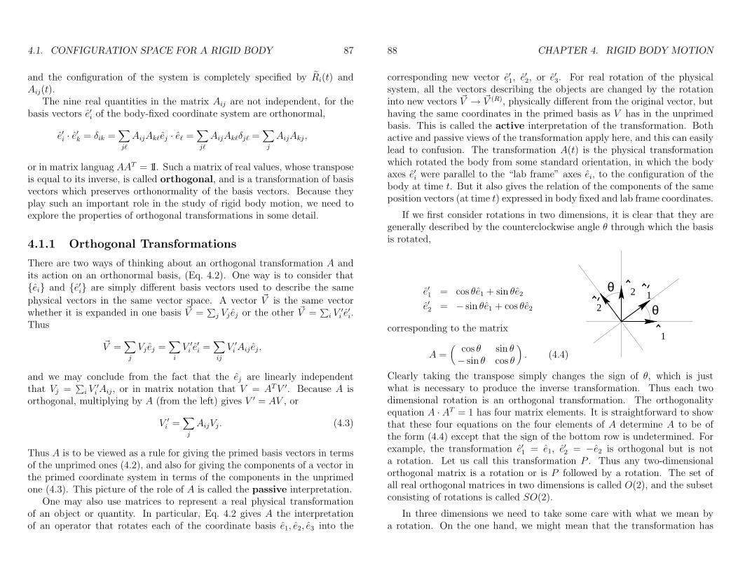
If we first consider rotations in two dimensions, it is clear that they aregenerally described by the counterclockwise angle θ through which the basisis rotated,
e′1 = cos θe1 + sin θe2
e′2 = − sin θe1 + cos θe2
corresponding to the matrix
A =(
cos θ sin θ− sin θ cos θ
). (4.4)
θ
1
21’’
^
^ ^
^
2θ
Clearly taking the transpose simply changes the sign of θ, which is justwhat is necessary to produce the inverse transformation. Thus each twodimensional rotation is an orthogonal transformation. The orthogonalityequation A · AT = 1 has four matrix elements. It is straightforward to showthat these four equations on the four elements of A determine A to be ofthe form (4.4) except that the sign of the bottom row is undetermined. Forexample, the transformation e′1 = e1, e
′2 = −e2 is orthogonal but is not
a rotation. Let us call this transformation P . Thus any two-dimensionalorthogonal matrix is a rotation or is P followed by a rotation. The set ofall real orthogonal matrices in two dimensions is called O(2), and the subsetconsisting of rotations is called SO(2).
In three dimensions we need to take some care with what we mean bya rotation. On the one hand, we might mean that the transformation has
4.1. CONFIGURATION SPACE FOR A RIGID BODY 89
some fixed axis and is a rotation through some angle about that axis. Letus call that a rotation about an axis. On the other hand, we might meanall transformations we can produce by a sequence of rotations about variousaxes. Let us define rotation in this sense. Clearly if we consider the rotationR which rotates the basis e into the basis e′, and if we have anotherrotation R′ which rotates e′ into e′′, then the transformation which firstdoes R and then does R′, called the composition of them, R = R′R, is alsoa rotation in this latter sense. As e′′i =
∑j R
′ij e
′j =
∑ij R
′ijRjkek, we see that
Rik =∑j R
′ijRjk and e′′i =
∑k Rikek. Thus the composition R = R′R is given
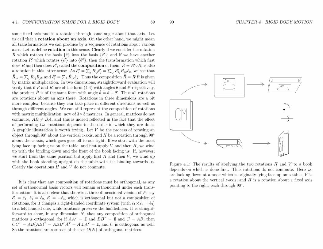
by matrix multiplication. In two dimensions, straightforward evaluation willverify that if R and R′ are of the form (4.4) with angles θ and θ′ respectively,the product R is of the same form with angle θ = θ + θ′. Thus all rotationsare rotations about an axis there. Rotations in three dimensions are a bitmore complex, because they can take place in different directions as well asthrough different angles. We can still represent the composition of rotationswith matrix multiplication, now of 3×3 matrices. In general, matrices do notcommute, AB 6= BA, and this is indeed reflected in the fact that the effectof performing two rotations depends in the order in which they are done.A graphic illustration is worth trying. Let V be the process of rotating anobject through 90 about the vertical z-axis, and H be a rotation through 90
about the x-axis, which goes goes off to our right. If we start with the booklying face up facing us on the table, and first apply V and then H, we windup with the binding down and the front of the book facing us. If, however,we start from the same position but apply first H and then V , we wind upwith the book standing upright on the table with the binding towards us.Clearly the operations H and V do not commute.
It is clear that any composition of rotations must be orthogonal, as anyset of orthonormal basis vectors will remain orthonormal under each trans-formation. It is also clear that there is a three dimensional version of P , saye′1 = e1, e
′2 = e2, e
′3 = −e3, which is orthogonal but not a composition of
rotations, for it changes a right-handed coordinate system (with e1× e2 = e3)to a left handed one, while rotations preserve the handedness. It is straight-forward to show, in any dimension N , that any composition of orthogonalmatrices is orthogonal, for if AAT = 1I and BBT = 1I and C = AB, thenCCT = AB(AB)T = ABBTAT = A 1IAT = 1I, and C is orthogonal as well.So the rotations are a subset of the set O(N) of orthogonal matrices.
90 CHAPTER 4. RIGID BODY MOTION
Figure 4.1: The results of applying the two rotations H and V to a bookdepends on which is done first. Thus rotations do not commute. Here weare looking down at a book which is originally lying face up on a table. V isa rotation about the vertical z-axis, and H is a rotation about a fixed axispointing to the right, each through 90.
4.1. CONFIGURATION SPACE FOR A RIGID BODY 91
4.1.2 Groups
This set of orthogonal matrices is a group, which means that the set O(N)satisfies the following requirements, which we state for a general set G.
A set G of elements A,B,C, ... together with a group multiplicationrule () for combining two of them, is a group if
• Given any two elements A and B in the group, the product A B isalso in the group. One then says that the set G is closed under .In our case the group multiplication is ordinary matrix multiplication,the group consists of all N ×N orthogonal real matrices, and we havejust shown that it is closed.
• The product rule is associative; for every A,B,C ∈ G, we have A (B C) = (A B) C. For matrix multiplication this is simply dueto the commutivity of finite sums,
∑i
∑j =
∑j
∑i.
• There is an element e in G, called the identity, such that for everyelement A ∈ G, e A = A e = A. In our case e is the unit matrix1I, 1Iij = δij.
• Every element A ∈ G has an element A−1 ∈ G such that A A−1 =A−1A = e. This element is called the inverse of A, and in the case oforthogonal matrices is the inverse matrix, which always exists, becausefor orthogonal matrices the inverse is the transpose, which always existsfor any matrix.
While the constraints (4.1) would permit A(t) to be any orthogonal ma-trix, the nature of Newtonian mechanics of a rigid body requires it to varycontinuously in time. If the system starts with A = 1I, there must be a contin-uous path in the space of orthogonal matrices to the configuration A(t) at anylater time. But the set of matrices O(3) is not connected in this fashion: thereis no path from A = 1I to A = P . To see it is true, we look at the determinantof A. From AAT = 1I we see that det(AAT ) = 1 = det(A) det(AT ) = (detA)2
so detA = ±1 for all orthogonal matrices A. But the determinant varies con-tinuously as the matrix does, so no continuous variation of the matrix canlead to a jump in its determinant. Thus the matrices which represent rota-tions have unit determinant, detA = +1, and are called unimodular.
The set of all unimodular orthogonal matrices in N dimensions is calledSO(N). It is a subset of O(N), the set of all orthogonal matrices in N
92 CHAPTER 4. RIGID BODY MOTION
dimensions. Clearly all rotations are in this subset. The subset is closedunder multiplication, and the identity and the inverses of elements in SO(N)are also in SO(N), for their determinants are clearly 1. Thus SO(N) is asubgroup of O(N). It is actually the set of rotations, but we shall provethis statement only for the case N = 3, which is the immediately relevantone. Simultaneously we will show that every rotation in three dimensions isa rotation about an axis. We have already proven it for N = 2. We nowshow that every A ∈ SO(3) has one vector it leaves unchanged or invariant,so that it is effectively a rotation in the plane perpendicular to this direction,or in other words a rotation about the axis it leaves invariant. The fact thatevery unimodular orthogonal matrix in three dimensions is a rotation aboutan axis is known as Euler’s Theorem. To show that it is true, we note thatif A is orthogonal and has determinant 1,
det(A− 1I)AT
= det(1I− AT ) = det(1I− A)
= det(A− 1I) det(A) = det(−(1I− A)) = (−1)3 det(1I− A)
= − det(1I− A),
so det(1I−A) = 0 and 1I−A is a singular matrix. Then there exists a vector~ω which is annihilated by it, (1I − A)~ω = 0, or A~ω = ~ω, and ~ω is invariantunder A. Of course this determines only the direction of ~ω, and only upto sign. If we choose a new coordinate system in which the z-axis pointsalong ~ω, we see that the elements Ai3 = (0, 0, 1), and orthogonality gives∑A2
3j = 1 = A233 so A31 = A32 = 0. Thus A is of the form
A =
(B )00
0 0 1
where B is an orthogonal unimodular 2 × 2 matrix, which is therefore arotation about the z-axis through some angle ω, which we may choose to bein the range ω ∈ (−π, π]. It is natural to define the vector ~ω, whose directiononly was determined above, to be ~ω = ωez. Thus we see that the set oforthogonal unimodular matrices is the set of rotations, and elements of thisset may be specified by a vector2 of length ≤ π.
2More precisely, we choose ~ω along one of the two opposite directions left invariant byA, so that the the angle of rotation is non-negative and ≤ π. This specifies a point in or onthe surface of a three dimensional ball of radius π, but in the case when the angle is exactlyπ the two diametrically opposed points both describe the same rotation. Mathematicianssay that the space of SO(3) is three-dimensional real projective space P3(R)[4].
4.2. KINEMATICS IN A ROTATING COORDINATE SYSTEM 93
Thus we see that the rotation which determines the orientation of a rigidbody can be described by the three degrees of freedom ~ω. Together withthe translational coordinates R, this parameterizes the configuration spaceof the rigid body, which is six dimensional. It is important to recognize thatthis is not motion in a flat six dimensional configuration space, however. Forexample, the configurations with ~ω = (0, 0, π − ε) and ~ω = (0, 0,−π + ε)approach each other as ε → 0, so that motion need not even be continuousin ~ω. The composition of rotations is by multiplication of the matrices, notby addition of the ~ω’s. There are other ways of describing the configurationspace, two of which are known as Euler angles and Cayley-Klein parameters,but none of these make describing the space very intuitive. For some purposeswe do not need all of the complications involved in describing finite rotations,but only what is necessary to describe infinitesimal changes between theconfiguration at time t and at time t+∆t. We will discuss these applicationsfirst. Later, when we do need to discuss the configuration in section 4.4.2,we will define Euler angles.
4.2 Kinematics in a rotating coordinate sys-
tem
We have seen that the rotations form a group. Let us describe the configu-ration of the body coordinate system by the position R(t) of a given pointand the rotation matrix A(t) : ei → e′i which transforms the canonical fixedbasis (inertial frame) into the body basis. A given particle of the body isfixed in the body coordinates, but this, of course, is not an inertial coordinatesystem, but a rotating and possibly accelerating one. We need to discuss thetransformation of kinematics between these two frames. While our currentinterest is in rigid bodies, we will first derive a general formula for rotating(and accelerating) coordinate systems.
Suppose a particle has coordinates~b(t) =∑i b′i(t)e
′i(t) in the body system.
We are not assuming at the moment that the particle is part of the rigidbody, in which case the b′i(t) would be independent of time. In the inertial
coordinates the particle has its position given by ~r(t) = R(t) +~b(t), but the
coordinates of ~b(t) are different in the space and body coordinates. Thus
ri(t) = Ri(t) + bi(t) = Ri(t) +∑j
(A−1(t)
)ijb′j(t).
94 CHAPTER 4. RIGID BODY MOTION
The velocity is ~v =∑i riei, because the ei are inertial and therefore consid-
ered stationary, so
~v = ˙R +∑ij
( ddtA−1(t)
)ij
b′j(t) +(A−1(t)
)ij
db′j(t)dt
ei,and not ˙R+
∑i(db
′i/dt)e
′i, because the e′i are themselves changing with time.
We might define a “body time derivative”
(~b)b:=
(d
dt~b
)b
:=∑i
(db′idt
)e′i,
but it is not the velocity of the particle α, even with respect to R(t), in thesense that physically a vector is basis independent, and its derivative requiresa notion of which basis vectors are considered time independent (inertial) andwhich are not. Converting the inertial evaluation to the body frame requires
the velocity to include the dA−1/dt term as well as the(~b)b
term.
What is the meaning of this extra term
V =∑ij
(d
dtA−1(t)
)ij
b′j(t)ei ?
The derivative is, of course,
V = lim∆t→0
1
∆t
∑ij
[A−1(t+ ∆t)ij − A−1(t)ij
]b′j(t)ei.
This expression has coordinates in the body frame with basis vectors fromthe inertial frame. It is better to describe it in terms of the body coordinatesand body basis vectors by inserting ei =
∑k(A
−1(t)ike′k(t) =
∑k Aki(t)e
′k(t).
Then we have
V =∑kj
e′k lim∆t→0
1
∆t
[A(t)A−1(t+ ∆t)− A(t)A−1(t)
]kjb′j(t).
The second term is easy enough to understand, as A(t)A−1(t) = 1I, so the
full second term is just ~b expressed in the body frame. The interpretation ofthe first term is suggested by its matrix form: A−1(t + ∆t) maps the body
4.2. KINEMATICS IN A ROTATING COORDINATE SYSTEM 95
basis at t + ∆t to the inertial frame, and A(t) maps this to the body basisat t. So together this is the infinitesimal rotation e′i(t + ∆t) → e′i(t). Thistransformation must be close to an identity, as ∆t→ 0. Let us expand it:
B := A(t)A−1(t+ ∆t) = 1I− Ω′∆t+O(∆t)2. (4.5)
Here Ω′ is a matrix which has fixed (finite) elements as ∆t → 0, and iscalled the generator of the rotation. Note B−1 = 1I + Ω′∆t to the order weare working, while the transpose BT = 1I−Ω′T∆t, so because we know B isorthogonal we must have that Ω′ is antisymmetric, Ω′ = −Ω′T , Ω′
ij = −Ω′ji.
Subtracting 1I from both sides of (4.5) and taking the limit shows thatthe matrix
Ω′(t) = −A(t) · ddtA−1(t) =
(d
dtA(t)
)· A−1(t),
where the latter equality follows from differentiating A · A−1 = 1I. Theantisymmetric 3 × 3 real matrix Ω′ is determined by the three off-diagonalelements above the diagonal, Ω′
23 = ω′1, Ω′13 = −ω′2, Ω′
12 = ω′3. as theothers are given by antisymmetry. Thus it is effectively a vector. It is veryuseful to express this relationship by defining the Levi-Civita symbol εijk,a totally antisymmetric rank 3 tensor specified by ε123 = 1. Then the aboveexpressions are given by Ω′
ij =∑k εijkω
′k, and we also have
1
2
∑ij
εkijΩ′ij =
1
2
∑ij`
εkijεij`ω′` = ω′k,
because, as explored in Appendix A.1,
εkij = εijk,∑i
εijkεipq = δjpδkq − δjqδkp, so∑ij
εijkεij` = 2δk`.
Thus ω′k and Ω′ij are essentially the same thing.
We have still not answered the question, “what is V?”
V =∑kj
e′k lim∆t→0
1
∆t[B − 1I]kj b
′j = −∑
kj
e′kΩ′kjb
′j = −∑
kj`
e′kεkj`ω′`b′j
= ~ω ×~b,where ~ω =
∑` ω
′`e′`. Note we have used Eq. A.4 for the cross-product. Thus
we have shown that
~v = ˙R + ~ω ×~b+ (~b)b, (4.6)
96 CHAPTER 4. RIGID BODY MOTION
and the second term, coming from V , represents the motion due to the ro-tating coordinate system.
When differentiating a true vector, which is independent of the originof the coordinate system, rather than a position, the first term in (4.6) is
absent, so in general for a vector ~C,
d
dt~C =
d~Cdt
b
+ ω × ~C. (4.7)
The velocity ~v is a vector, as are ˙R and~b, the latter because it is the differenceof two positions. The angular velocity ~ω is also a vector3, and its derivativeis particularly simple, because
~ω =d
dt~ω =
(d~ω
dt
)b
+ ~ω × ~ω =
(d~ω
dt
)b
. (4.8)
Another way to understand (4.7) is as a simple application of Leibnitz’
rule to ~C =∑C ′ie
′i, noting that
d
dte′i(t) =
∑j
d
dtAij(t)ej =
∑j
(Ω′A)ij ej =∑k
Ω′ike
′k,
which means that the second term from Leibnitz is∑C ′i
d
dte′i(t) =
∑ik
C ′iΩ′ike
′k =
∑ijk
C ′iεikjω′j e′k = ~ω × ~C,
as given in (4.7). This shows that even the peculiar object (~b)b obeys (4.7).Applying this to the velocity itself (4.6), we find the acceleration
~a =d
dt~v =
d
dt˙R +
dω
dt×~b+ ω × d
dt~b+
d
dt(~b)b
= ¨R + ~ω ×~b+ ω ×d~b
dt
b
+ ~ω ×~b+
d2~b
dt2
b
+ ω ×d~bdt
b
= ¨R +
d2~b
dt2
b
+ 2ω ×d~bdt
b
+ ~ω ×~b+ ~ω ×(ω ×~b
).
3Actually ~ω is a pseudovector, which behaves like a vector under rotations but changessign compared to what a vector does under reflection in a mirror.
4.3. THE MOMENT OF INERTIA TENSOR 97
This is a general relation between any orthonormal coordinate system andan inertial one, and in general can be used to describe physics in noninertialcoordinates, regardless of whether that coordinate system is imbedded in arigid body. The full force on the particle is ~F = m~a, but if we use ~r, ~v ′, and~a ′ to represent ~b, (d~b/dt)b and (d2~b/dt2)b respectively, we have an expressionfor the apparent force
m~a ′ = ~F −m ¨R− 2m~ω ×~v ′ −m~ω × ~r −m~ω × (~ω × ~r).
The additions to the real force are the pseudoforce for an accelerating refer-
ence frame −m ¨R, the Coriolus force −2m~ω×~v ′, an unnamed force involvingthe angular acceleration of the coordinate system −m~ω×~r, and the centrifu-gal force −m~ω × (~ω × ~r) respectively.
4.3 The moment of inertia tensor
Let us return to a rigid body, where the particles are constrained to keepthe distances between them constant. Then the coordinates b′αi in the bodyframe are independant of time, and
~vα = ˙R + ω ×~bαso the individual momenta and the total momentum are
~pα = mαV +mα~ω ×~bα~P = MV + ~ω ×∑
α
mα~bα
= MV +M~ω × ~B
where ~B is the center of mass position relative to the marked point R.
4.3.1 Motion about a fixed point
Angular Momentum
We next evaluate the total angular momentum, ~L =∑α ~rα × pα. We will
first consider the special case in which the body is rotating about the origin,so R ≡ 0, and then we will return to the general case. As ~pα = mα~ω ×~bα
98 CHAPTER 4. RIGID BODY MOTION
already involves a cross product, we will find a triple product, and will usethe reduction formula4
~A×(~B × ~C
)= ~B
(~A · ~C
)− ~C
(~A · ~B
).
Thus
~L =∑α
mα~bα ×
(~ω ×~bα
)(4.9)
= ~ω∑α
mα~b 2α −
∑α
mα~bα(~bα · ~ω
). (4.10)
We see that, in general, ~L need not be parallel to the angular velocity ~ω, but itis always linear in ~ω. Thus it is possible to generalize the equation ~L = I~ω ofelementary physics courses, but we need to generalize I from a multiplicativenumber to a linear operator which maps vectors into vectors, not necessarilyin the same direction. In component language this linear operation is clearlyin the form Li =
∑j Iijωj, so I is a 3× 3 matrix. Rewriting (4.10), we have
Li = ωi∑α
mα~b 2α −
∑α
mαbαi(~bα · ~ω
).
=∑j
∑α
mα
(~b 2αδij − bαibαj
)ωj
≡ ∑j
Iijωj,
whereIij =
∑α
mα
(~b 2αδij − bαibαj
)(4.11)
is the inertia tensor about the fixed point R. In matrix form, we now have(4.10) as
~L = I · ~ω, (4.12)
where I · ~ω means a vector with components (I · ~ω)i =∑j Iijωj.
If we consider the rigid body in the continuum limit, the sum over particlesbecomes an integral over space times the density of matter,
Iij =∫d3b ρ(~b)
(~b 2δij − bibj
). (4.13)
4This formula is colloquially known as the bac-cab formula. It is proven in AppendixA.1.
4.3. THE MOMENT OF INERTIA TENSOR 99
Kinetic energy
For a body rotating about the origin
T =1
2
∑α
mα~v2α =
1
2
∑α
mα
(~ω ×~bα
)·(~ω ×~bα
).
From the general 3-dimensional identity5(~A× ~B
)·(~C × ~D
)= ~A · ~C ~B · ~D − ~A · ~D ~B · ~C,
we have
T =1
2
∑α
mα
[~ω 2~b 2
α −(~ω ·~bα
)2]
=1
2
∑ij
ωiωj∑α
mα
(~b 2αδij −~bαi~bαj
)=
1
2
∑ij
ωiIijωj. (4.14)
or
T =1
2~ω · I · ~ω.
Noting that∑j Iijωj = Li, T = 1
2~ω · ~L for a rigid body rotating about the
origin, with ~L measured from that origin.
4.3.2 More General Motion
When the marked point R is not fixed in space, there is nothing special aboutit, and we might ask whether it would be better to evaluate the moment ofinertia about some other point. Working in the body-fixed coordinates, wemay consider a given point ~b and evaluate the moment of inertia about thatpoint, rather than about the origin. This means ~bα is replaced by ~bα −~b, so
I(~b )ij =
∑α
mα
[(~bα −~b
)2δij − (bαi − bi) (bαj − bj)
]= I
(0)ij +M
[(−2~b · ~B + b2
)δij +Bibj + biBj − bibj
], (4.15)
where we recall that ~B is the position of the center of mass with respect to R,the origin of the body fixed coordinates6. Subtracting the moment of inertia
5See Appendix A for a hint on how to derive this.6I(0) is evaluated about the body-fixed position ~b = 0, or about R, so it is given by Eq.
4.11.
100 CHAPTER 4. RIGID BODY MOTION
about the center of mass, given by (4.15) with b→ B, we have
I(~b )ij − I
( ~B )ij = M
[(−2~b · ~B + b2 +B2
)δij +Bibj + biBj − bibj −BiBj
]= M
[(~b− ~B
)2δij − (bi −Bi) (bj −Bj)
]. (4.16)
Note the difference is independent of the origin of the coordinate system,depending only on the vector b = ~b− ~B.
A possible axis of rotation can be specified by a point ~b through whichit passes, together with a unit vector n in the direction of the axis7. The
moment of inertia about the axis (~b, n) is defined as n·I(~b )·n. If we comparethis to the moment about a parallel axis through the center of mass, we seethat
n · I(~b ) · n− n · I(cm) · n = M[b2n2 − (b · n)2
]= M(n× b)2 = Mb2⊥, (4.17)
where b⊥ is the projection of the vector, from the center of mass to ~b, ontothe plane perpendicular to the axis. Thus the moment of inertia about anyaxis is the moment of inertia about a parallel axis through the center ofmass, plus M`2, where ` = b⊥ is the distance between these two axes. Thisis known as the parallel axis theorem.
The general motion of a rigid body involves both a rotation and a trans-lation of a given point R. Then
~rα = R +~bα, ~rα = V + ~ω ×~bα, (4.18)
where V and ~ω may be functions of time, but they are the same for allparticles α. Then the angular momentum about the origin is
~L =∑α
mα~rα × ~rα =∑α
mα~rα × V +∑α
mα
(R +~bα
)×(~ω ×~bα
)= M ~R× V + I(0) · ~ω +MR× (~ω × ~B), (4.19)
where the inertia tensor I(0) is still measured8 about R, even though that isnot a fixed point. Recall that ~R is the laboratory position of the center of
7Actually, this gives more information than is needed to specify an axis, as ~b and ~b ′
specify the same axis if ~b−~b ′ ∝ n. In the expression for the moment of inertia about theaxis, (4.17), we see that the component of ~b parallel to n does not affect the result.
8 Recall the (~b) superscript in (4.15) refers to the body-fixed coordinate, so I(0) is about~b = 0, not about the origin in inertial coordinates.
4.3. THE MOMENT OF INERTIA TENSOR 101
mass, while ~B is its position in the body-fixed system. The kinetic energy isnow
T =∑α
1
2mα~r
2
α =1
2
∑α
mα
(V + ~ω ×~bα
)·(V + ~ω ×~bα
)=
1
2
∑α
mαV2 + V ·
(~ω ×∑
α
mα~bα
)+
1
2
∑α
mα
(~ω ×~bα
)2
=1
2MV 2 +MV ·
(~ω × ~B
)+
1
2~ω · I(0) · ~ω (4.20)
and again the inertia tensor I(0) is calculated about the arbitrary point R.We will see that it makes more sense to use the center of mass.
Simplification Using the Center of Mass
As each ~rα = V + ~ω ×~bα, the center of mass velocity is given by
M~V =∑α
mα~rα =∑α
mα
(V + ~ω ×~bα
)= M
(V + ~ω × ~B
), (4.21)
so 12M~V 2 = 1
2MV 2 +MV · (~ω × ~B) + 1
2M(ω × ~B)2. Comparing with 4.20,
we see that
T =1
2M~V 2 − 1
2M(~ω × ~B)2 +
1
2~ω · I(0) · ~ω.
The last two terms can be written in terms of the inertia tensor about thecenter of mass. From 4.16 with ~b = 0, as ~B is the center of mass,
I(cm)ij = I
(0)ij −MB2δij +MBiBj.
Using the formula for(~A× ~B
)·(~C × ~D
)again,
T =1
2M~V 2 − 1
2M[~ω2 ~B2 −
(~ω · ~B
)2]
+1
2~ω · I(0) · ~ω
=1
2M~V 2 +
1
2~ω · I(cm) · ~ω. (4.22)
A similar expression holds for the angular momentum. Inserting V = ~V −~ω × ~B into (4.19),
~L = M ~R×[~V − ~ω × ~B
]+ I(0) · ~ω +MR× (~ω × ~B)
102 CHAPTER 4. RIGID BODY MOTION
= M ~R× ~V −M(~R− R)× (~ω × ~B) + I(0) · ~ω= M ~R× ~V −M ~B × (~ω × ~B) + I(0) · ~ω= M ~R× ~V −M~ωB2 +M ~B ~ω · ~B + I(0) · ~ω= M ~R× ~V + I(cm) · ~ω. (4.23)
These two decompositions, (4.22) and (4.23), have a reasonable interpre-tation: the total angular momentum is the angular momentum about thecenter of mass, plus the angular momentum that a point particle of massM and position ~R(t) would have. Similiarly, the total kinetic energy is therotational kinetic energy of the body rotating about its center of mass, plusthe kinetic energy of the fictious point particle moving with the center ofmass.
Note that if we go back to the situation where the marked point R isstationary at the origin of the lab coordinates, V = 0, ~L = I · ~ω, T =12~ω · I · ~ω = 1
2~ω · ~L.
The angular momentum in Eqs. 4.19 and 4.23 is the angular momentummeasured about the origin of the lab coordinates, ~L =
∑αmα~rα × vα. It is
useful to consider the angular momentum as measured about the center ofmass,
~L cm =∑α
mα
(~rα − ~R
)×(~vα − ~V
)= ~L−M ~R× ~V , (4.24)
so we see that the angular momentum, measured about the center of mass,is just I(cm) · ~ω.
The parallel axis theorem is also of the form of a decomposition. Theinertia tensor about a given point ~r given by (4.16) is
I(r)ij = I
(cm)ij +M
[(~r − ~R
)2δij − (ri −Ri) (rj −Rj)
].
This is, once again, the sum of the quantity, here the inertia tensor, of thebody about the center of mass, plus the value a particle of mass M at thecenter of mass ~R would have, evaluated about ~r.
There is another theorem about moments of inertia, though much lessgeneral — it only applies to a planar object — let’s say in the xy plane, sothat zα ≈ 0 for all the particles constituting the body. As
Izz =∑α
mα
(x2α + y2
α
)
4.3. THE MOMENT OF INERTIA TENSOR 103
Ixx =∑α
mα
(y2α + z2
α
)=∑α
mαy2α
Iyy =∑α
mα
(x2α + z2
α
)=∑α
mαx2α,
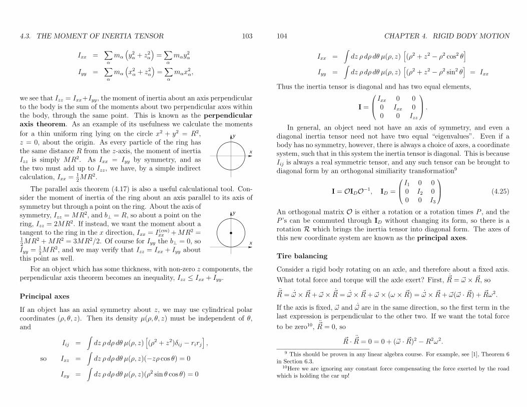
we see that Izz = Ixx+Iyy, the moment of inertia about an axis perpendicularto the body is the sum of the moments about two perpendicular axes withinthe body, through the same point. This is known as the perpendicularaxis theorem. As an example of its usefulness we calculate the moments
for a thin uniform ring lying on the circle x2 + y2 = R2,z = 0, about the origin. As every particle of the ring hasthe same distance R from the z-axis, the moment of inertiaIzz is simply MR2. As Ixx = Iyy by symmetry, and asthe two must add up to Izz, we have, by a simple indirectcalculation, Ixx = 1
2MR2.
x
y
The parallel axis theorem (4.17) is also a useful calculational tool. Con-sider the moment of inertia of the ring about an axis parallel to its axis ofsymmetry but through a point on the ring. About the axis ofsymmetry, Izz = MR2, and b⊥ = R, so about a point on thering, Izz = 2MR2. If instead, we want the moment about atangent to the ring in the x direction, Ixx = I(cm)
xx +MR2 =12MR2 +MR2 = 3MR2/2. Of course for Iyy the b⊥ = 0, soIyy = 1
2MR2, and we may verify that Izz = Ixx + Iyy about
this point as well.
y
x
For an object which has some thickness, with non-zero z components, theperpendicular axis theorem becomes an inequality, Izz ≤ Ixx + Iyy.
Principal axes
If an object has an axial symmetry about z, we may use cylindrical polarcoordinates (ρ, θ, z). Then its density µ(ρ, θ, z) must be independent of θ,and
Iij =∫dz ρ dρ dθ µ(ρ, z)
[(ρ2 + z2)δij − rirj
],
so Ixz =∫dz ρ dρ dθ µ(ρ, z)(−zρ cos θ) = 0
Ixy =∫dz ρ dρ dθ µ(ρ, z)(ρ2 sin θ cos θ) = 0
104 CHAPTER 4. RIGID BODY MOTION
Ixx =∫dz ρ dρ dθ µ(ρ, z)
[(ρ2 + z2 − ρ2 cos2 θ
]Iyy =
∫dz ρ dρ dθ µ(ρ, z)
[(ρ2 + z2 − ρ2 sin2 θ
]= Ixx
Thus the inertia tensor is diagonal and has two equal elements,
I =
Ixx 0 00 Ixx 00 0 Izz
.In general, an object need not have an axis of symmetry, and even a
diagonal inertia tensor need not have two equal “eigenvalues”. Even if abody has no symmetry, however, there is always a choice of axes, a coordinatesystem, such that in this system the inertia tensor is diagonal. This is becauseIij is always a real symmetric tensor, and any such tensor can be brought todiagonal form by an orthogonal similiarity transformation9
I = OIDO−1, ID =
I1 0 00 I2 00 0 I3
(4.25)
An orthogonal matrix O is either a rotation or a rotation times P , and theP ’s can be commuted through ID without changing its form, so there is arotation R which brings the inertia tensor into diagonal form. The axes ofthis new coordinate system are known as the principal axes.
Tire balancing
Consider a rigid body rotating on an axle, and therefore about a fixed axis.
What total force and torque will the axle exert? First, ~R = ~ω × ~R, so
~R = ~ω × ~R + ~ω × ~R = ~ω × ~R + ~ω × (ω × ~R) = ~ω × ~R + ~ω(~ω · ~R) + ~Rω2.
If the axis is fixed, ~ω and ~ω are in the same direction, so the first term in thelast expression is perpendicular to the other two. If we want the total force
to be zero10, ~R = 0, so
~R · ~R = 0 = 0 + (~ω · ~R)2 −R2ω2.
9 This should be proven in any linear algebra course. For example, see [1], Theorem 6in Section 6.3.
10Here we are ignoring any constant force compensating the force exerted by the roadwhich is holding the car up!
4.3. THE MOMENT OF INERTIA TENSOR 105
Thus the angle between ~ω and ~R is 0 or π, and the center of mass must lieon the axis of rotation. This is the condition of static balance if the axis ofrotation is horizontal in a gravitational field. Consider a car tire: to be stableat rest at any angle, ~R must lie on the axis or there will be a gravitationaltorque about the axis, causing rotation in the absense of friction. If the tireis not statically balanced, this force will rotate rapidly with the tire, leadingto vibrations of the car.
Even if the net force is 0, there might be a torque. ~τ = ~L = d(I · ~ω)/dt.
If I · ~ω is not parallel to ~ω it will rotate with the wheel, and so ~L will rapidlyoscillate. This is also not good for your axle. If, however, ~ω is parallel toone of the principal axes, I · ~ω is parallel to ~ω, so if ~ω is constant, so is ~L,and ~τ = 0. The process of placing small weights around the tire to causeone of the principal axes to be aligned with the axle is called dynamicalbalancing.
Every rigid body has its principal axes; the problem of finding themand the moments of inertia about them, given the inertia tensor I in somecoordiate system, is a mathematical question of finding a rotation R and“eigenvalues” I1, I2, I3 (not components of a vector) such that equation 4.25
holds, with R in place of O. The vector ~v1 = R 1
00
is then an eigenvector,
for
I · ~v1 = RIDR−1R 1
00
= RID
100
= I1R 1
00
= I1~v1.
Similarly I ·~v2 = I2~v2 and I ·~v3 = I3~v3, where ~v2 and ~v3 are defined the sameway, starting with e2 and e3 instead of e1. Note that, in general, I acts simplyas a multiplier only for multiples of these three vectors individually, and notfor sums of them. On a more general vector I will change the direction aswell as the length of the vector it acts on.
Note that the Ii are all ≥ 0, for given any vector ~n,
~n · I · ~n =∑α
mα[r2αn
2 − (~rα · ~n)2] =∑α
mαr2αn
2(1− cos2 θα) ≥ 0,
so all the eigenvalues must be ≥ 0. It will be equal to zero only if all massivepoints of the body are in the ±~n directions, in which case the rigid bodymust be a thin line.
106 CHAPTER 4. RIGID BODY MOTION
Finding the eigenvalues Ii is easier than finding the rotation R. Considerthe matrix I−λ1I, which has the same eigenvectors as I, but with eigenvaluesIi − λ. Then if λ is one of the eigenvalues Ii, this matrix will annihilate ~vi,so I−λ1I is a singular matrix with zero determinant. Thus the characteristicequation det(I − λ1I) = 0, which is a cubic equation in λ, gives as its rootsthe eigenvalues of I.
4.4 Dynamics
4.4.1 Euler’s Equations
So far, we have been working in an inertial coordinate system O. In compli-cated situations this is rather unnatural; it is more natural to use a coordiatesystem O′ fixed in the rigid body. In such a coordinate system, the vectorone gets by differentiating the coefficients of a vector ~b =
∑b′ie
′i differs from
the inertial derivative ~b as given in Eq. 4.7. Consider two important specialcases: either we have a system rotating about a fixed point R, with ~τ , ~L, andI ′ij all evaluated about that fixed point, or we are working about the center
of mass, with ~τ , ~L, and I ′ij all evaluated about the center of mass, even if it
is in motion. In either case, we have ~L = I′ · ~ω, so for the time derivative ofthe angular momentum, we have
~τ =d~L
dt=
d~Ldt
b
+ ~ω × ~L
=∑ij
d(I ′ijω′j)
dte′i + ~ω × (I ′ · ~ω),
Now in the O′ frame, all the masses are at fixed positions, so I ′ij is constant,
and the first term is simply I · (dω/dt)b, which by (4.8) is simply I · ~ω. Thuswe have (in the body coordinate system)
~τ = I′ · ~ω + ~ω × (I′ · ω). (4.26)
We showed that there is always a choice of cartesian coordinates mountedon the body along the principal axes. For the rest of this section we will usethis body-fixed coordinate system, so we will drop the primes.
4.4. DYNAMICS 107
The torque not only determines the rate of change of the angular momen-tum, but also does work in the system. For a system rotating about a fixedpoint, we see from the expression (4.14), T = 1
2~ω · I · ~ω, that
dT
dt=
1
2~ω · I · ~ω +
1
2~ω · I · ~ω +
1
2~ω · I · ~ω.
The first and last terms are equal because the inertia tensor is symmetric,Iij = Iji, and the middle term vanishes in the body-fixed coordinate system
because all particle positions are fixed. Thus dT/dt = ~ω · I · ~ω = ~ω · ~L = ~ω ·~τ .Thus the kinetic energy changes due to the work done by the external torque.Therefore, of course, if there is no torque the kinetic energy is constant.
We will write out explicitly the components of Eq. 4.26. In evaluating τ1,we need the first component of the second term,
[(ω1, ω2, ω3)× (I1ω1, I2ω2, I3ω3)]1 = (I3 − I2)ω2ω3.
Inserting this and the similar expressions for the other components intoEq. (4.26), we get Euler’s equations
τ1 = I1ω1 + (I3 − I2)ω2ω3,
τ2 = I2ω2 + (I1 − I3)ω1ω3, (4.27)
τ3 = I3ω3 + (I2 − I1)ω1ω2.
Using these equations we can address several situations of increasing diffi-culty.
First, let us ask under what circumstances the angular velocity will befixed in the absense of a torque. As ~τ = ~ω = 0, from the 1-componentequation we conclude that (I2 − I3)ω2ω3 = 0. Then either the momentsare equal (I2 = I3) or one of the two components ω2 or ω3 must vanish.Similarly, if I1 6= I2, either ω1 or ω2 vanishes. So the only way more than onecomponent of ~ω can be nonzero is if two or more of the principal momentsare equal. In this case, the principal axes are not uniquely determined. Forexample, if I1 = I2 6= I3, the third axes is unambiguously required as oneof the principle axes, but any direction in the (12)-plane will serve as thesecond principal axis. In this case we see that ~τ = ~ω = 0 implies either ~ω isalong the z-axis (ω1 = ω2 = 0) or it lies in the (12)-plane, (ω3 = 0). In anycase, the angular velocity is constant in the absence of torques only if it liesalong a principal axis of the body.
108 CHAPTER 4. RIGID BODY MOTION
As our next example, consider an axially symmetric body with no external
forces or torques acting on it. Then ~R is a constant, and we will choose towork in an inertial frame where ~R is fixed at the origin. Choosing our body-fixed coordinates with z along the axis of symmetry, our axes are principalones and I1 = I2, so we have
I1ω1 = (I1 − I3)ω2ω3,
I1ω2 = (I3 − I1)ω1ω3,
I3ω3 = (I1 − I2)ω1ω2 = 0.
We see that ω3 is a constant. Let Ω = ω3(I3 − I1)/I1. Then we see that
ω1 = −Ωω2, ω2 = Ωω1.
Differentiating the first and plugging in the second, we find
ω1 = −Ωω2 = −Ω2ω1,
which is just the harmonic oscillator equation. So ω1 = A cos(Ωt + φ) withsome arbitrary amplitude A and constant phase φ, and ω2 = −ω1/Ω =A sin(Ωt + φ). We see that, in the body-fixed frame, the angular velocityrotates about the axis of symmetry in a circle, with arbitrary radius A, anda period 2π/Ω. The angular velocity vector ~ω is therefore sweeping out acone, called the body cone of precession with a half-angle φb = tan−1A/ω3.Note the length of ~ω is fixed.
What is happening in the lab frame? The kinetic energy 12~ω·~L is constant,
as is the vector ~L itself. As the length of a vector is frame independent, |~ω|is fixed as well. Therefore the angle between them, called the lab angle, isconstant,
cosφL =~ω · ~L|~ω||~L| =
2T
|~ω||~L| = constant. (4.28)
Thus ~ω rotates about ~L in a cone, called the laboratory cone.Note that φb is the angle between ~ω and the z-axis of the body, while φL
is the angle between ~ω and ~L, so they are not the same angle in two differentcoordinate systems.
The situation is a bit hard to picture. In the body frame it is hardto visualize ~ω, although that is the negative of the angular velocity of theuniverse in that system. In the lab frame the body is instantanously rotating
4.4. DYNAMICS 109
about the axis ~ω, but this axis is not fixed in the body. At any instant,the points on this line are not moving, and we may think of the body rollingwithout slipping on the lab cone, with ~ω the momentary line of contact. Thusthe body cone rolls on the lab cone without slipping.
The Poinsot construction
This idea has an extension to the more general case where the body has nosymmetry. The motion in this case can be quite complex, both for analyticsolution, because Euler’s equations are nonlinear, and to visualize, becausethe body is rotating and bobbing around in a complicated fashion. But aswe are assuming there are no external forces or torques, the kinetic energyand total angular momentum vectors are constant, and this will help usunderstand the motion. To do so we construct an abstract object called theinertia ellipsoid. Working in the body frame, consider that the equation
2T =∑ij
ωiIijωj = f(~ω)
is a quadratic equation for ~ω, with constant coefficients, which thereforedetermines an ellipsoid11 in the space of possible values of ~ω. This is calledthe inertia ellipsoid12. It is fixed in the body, and so if we were to scale itby some constant to change units from angular velocity to position, we couldthink of it as a fixed ellipsoid in the body itself, centered at the center ofmass. At every moment the instantanous value of ~ω must lie on this ellipsoid,so ~ω(t) sweeps out a path on this ellipsoid called the polhode.
If we go to the lab frame, we see this ellipsoid fixed in and moving withthe body. The instantaneous value of ~ω still lies on it. In addition, thecomponent of ~ω in the (fixed) ~L direction is fixed, and as the center of mass
is fixed, the point corresponding to ~ω lies in a plane perpendicular to ~L a fixeddistance from the center of mass, known as the invariant plane. Finally wenote that the normal to the surface of the ellipsoid f(~ω) = 2T is parallel to
∇f = 2I · ~ω = 2~L, so the ellipsoid of inertia is tangent to the invariant plane
11We assume the body is not a thin line, so that I is a positive definite matrix (all itseigenvalues are strictly > 0), so the surface defined by this equation is bounded.
12Exactly which quantity forms the inertia ellipsoid varies by author. Goldstein scales~ω by a constant 1/
√2T to form an object ρ whose ellipsoid he calls the inertia ellipsoid.
Landau and Lifshitz discuss an ellipsoid of ~L values but don’t give it a name. They thencall the corresponding path swept out by ~ω the polhode, as we do.
110 CHAPTER 4. RIGID BODY MOTION
at the point ~ω(t). The path that ~ω(t) sweeps out on the invariant plane iscalled the herpolhode. At this particular moment, the point correspondingto ~ω in the body is not moving, so the inertia ellipsoid is rolling, not slipping,on the invariant plane.
In general, if there is no special symmetry, the inertia ellipsoid will notbe axially symmetric, so that in order to roll on the fixed plane and keep itscenter at a fixed point, it will need to bob up and down. But in the specialcase with axial symmetry, the inertia ellipsoid will also have this symmetry,so it can roll about a circle, with its symmetry axis at a fixed angle relativeto the invariant plane. In the body frame, ω3 is fixed and the polhode moveson a circle of radius A = ω sinφb. In the lab frame, ~ω rotates about ~L, soit sweeps out a circle of radius ω sinφL in the invariant plane. One circle isrolling on the other, and the polhode rotates about its circle at the rate Ω inthe body frame, so the angular rate at which the herpolhode rotates about~L, ΩL, is
ΩL = Ωcircumference of polhode circle
circumference of herpolhode circle=I3 − I1I1
ω3sinφbsinφL
.
Stability of rotation about an axis
We have seen that the motion of a isolated rigid body is simple only if theangular velocity is along one of the principal axes, and can be very complexotherwise. However, it is worth considering what happens if ~ω is very nearly,but not exactly, along one of the principal axes, say z. Then we may write~ω = ω3e3 + ~ε in the body coordinates, and assume ε3 = 0 and the othercomponents are small. We treat Euler’s equations to first order in the smallquantity ~ε. To this order, ω3 = (I1− I2)ε1ε2/I3 ≈ 0, so ω3 may be considereda constant. The other two equations give
ω1 = ε1 =I2 − I3I1
ε2ω3
ω2 = ε2 =I3 − I1I2
ε1ω3
so
ε1 =I2 − I3I1
I3 − I1I2
ω23ε1.
What happens to ~ε(t) depends on the sign of the coefficient, or the signof (I2 − I3)(I3 − I1). If it is negative, ε1 oscillates, and indeed ~ε rotates
4.4. DYNAMICS 111
about z just as we found for the symmetric top. This will be the case ifI3 is either the largest or the smallest eigenvalue. If, however, it is themiddle eigenvalue, the constant will be positive, and the equation is solved byexponentials, one damping out and one growing. Unless the initial conditionsare perfectly fixed, the growing piece will have a nonzero coefficient and ~ε willblow up. Thus a rotation about the intermediate principal axis is unstable,while motion about the axes with the largest and smallest moments arestable. For the case where two of the moments are equal, the motion will bestable about the third, and slightly unstable (~ε will grow linearly instead ofexponentially with time) about the others.
An interesting way of understanding this stability or instability of rotationclose to a principle axes involves another ellipsoid we can define for the freerigid body, an ellipsoid of possible angular momentum values. Of coursein the inertial coordinates ~L is constant, but in body fixed language thecoordinates vary with time, though the length of ~L is still constant. Inaddition, the conservation of kinetic energy
2T = ~L · I−1 · ~L(where I−1 is the inverse of the moment of inertia matrix) gives a quadratic
equation for the three components of ~L, just as we had for ~ω and the ellipsoidof inertia. The path of ~L(t) on this ellipsoid is on the intersection of the
ellisoid with a sphere of radius |~L|, for the length is fixed.
If ~ω is near the principle axis with the largest moment of inertia, ~L liesnear the major axis of the ellipsoid. The sphere is nearly circumscribing theellipsoid, so the intersection consists only of two small loops surrounding eachend of the major axis. Similiarly if ~ω is near the smallest moment, the sphereis nearly inscribed in the ellipsoid, and again the possible values of ~L lie closeto either end of the minor axis. Thus the subsequent motion is confined toone of these small loops. But if ~ω starts near the intermediate principle axis,~L does likewise, and the intersection consists of two loops which extend fromnear one end to near the other of the intermediate axis, and the possiblecontinuous motion of ~L is not confined to a small region of the ellipsoid.
Because the rotation of the Earth flattens the poles, the Earth is approx-imately an oblate ellipsoid, with I3 greater than I1 = I2 by about one partin 300. As ω3 is 2π per siderial day, if ~ω is not perfectly aligned with theaxis, it will precess about the symmetry axis once every 10 months. ThisChandler wobble is not of much significance, however, because the bodyangle φb ≈ 10−6.
112 CHAPTER 4. RIGID BODY MOTION
4.4.2 Euler angles
Up to this point we have managed to describe the motion of a rigid bodywithout specifying its coordinates. This is not possible for most problemswith external forces, for which the torque will generally depend on the ori-entation of the body. It is time to face up to the problem of using threegeneralized coordinates to describe the orientation.
In section 4.1.1 we described the orientation of a rigid body in terms of arotation through a finite angle in a given direction, specified by ω. This doesnot give a simple parameterization of the matrix A, and it is more commonto use an alternate description known as Euler angles. Here we describethe rotation A as a composition of three simpler rotations about specifiedcoordinates, so that we are making a sequence of changes of coordinates
(x, y, z)Rz(φ)−→ (x1, y1, z1)
Ry1(θ)−→ (x2, y2, z2)Rz2(ψ)−→ (x′, y′, z′).
We have chosen three specific directions about which to make the three ro-tations, namely the original z-axis, the next y-axis, y1, and then the newz-axis, which is both z2 and z′. This choice is not universal, but is the onegenerally used in quantum mechanics. Many of the standard classical me-chanics texts13 take the second rotation to be about the x1-axis instead ofy1, but quantum mechanics texts14 avoid this because the action of Ry on aspinor is real, while the action of Rx is not. While this does not concern ushere, we prefer to be compatible with quantum mechanics discussions.
This procedure is pictured in Figure 4.2. To see that any rotation canbe written in this form, and to determine the range of the angles, we firstdiscuss what fixes the y1 axis. Notice that the rotation about the z-axisleaves z uneffected, so z1 = z, Similiarly, the last rotation leaves the z2axis unchanged, so it is also the z′ axis. The planes orthogonal to theseaxes are also left invariant15. These planes, the xy-plane and the x′y′-planerespectively, intersect in a line called the line of nodes16. These planesare also the x1y1 and x2y2 planes respectively, and as the second rotation
13 See [2], [6], [9], [10], [11] and [17].14For example [13] and [20].15although the points in the planes are rotated by 4.4.16The case where the xy and x′y′ are identical, rather than intersecting in a line, is
exceptional, corresponding to θ = 0 or θ = π. Then the two rotations about the z-axisadd or subtract, and many choices for the Euler angles (φ, ψ) will give the same fullrotation.
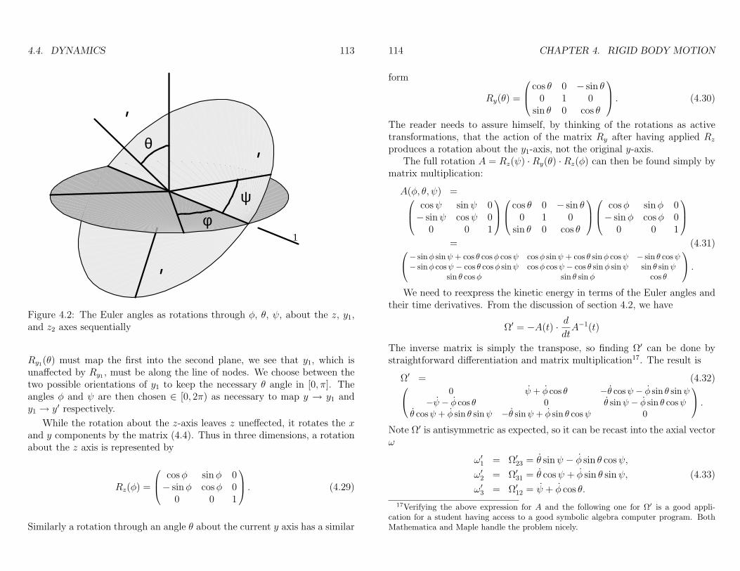
4.4. DYNAMICS 113
θ
φψ
’
’
’
1
Figure 4.2: The Euler angles as rotations through φ, θ, ψ, about the z, y1,and z2 axes sequentially
Ry1(θ) must map the first into the second plane, we see that y1, which isunaffected by Ry1 , must be along the line of nodes. We choose between thetwo possible orientations of y1 to keep the necessary θ angle in [0, π]. Theangles φ and ψ are then chosen ∈ [0, 2π) as necessary to map y → y1 andy1 → y′ respectively.
While the rotation about the z-axis leaves z uneffected, it rotates the xand y components by the matrix (4.4). Thus in three dimensions, a rotationabout the z axis is represented by
Rz(φ) =
cosφ sinφ 0− sinφ cosφ 0
0 0 1
. (4.29)
Similarly a rotation through an angle θ about the current y axis has a similar
114 CHAPTER 4. RIGID BODY MOTION
form
Ry(θ) =
cos θ 0 − sin θ0 1 0
sin θ 0 cos θ
. (4.30)
The reader needs to assure himself, by thinking of the rotations as activetransformations, that the action of the matrix Ry after having applied Rz
produces a rotation about the y1-axis, not the original y-axis.The full rotation A = Rz(ψ) ·Ry(θ) ·Rz(φ) can then be found simply by
matrix multiplication:
A(φ, θ, ψ) = cosψ sinψ 0− sinψ cosψ 0
0 0 1
cos θ 0 − sin θ
0 1 0sin θ 0 cos θ
cosφ sinφ 0− sinφ cosφ 0
0 0 1
= (4.31)− sinφ sinψ + cos θ cosφ cosψ cosφ sinψ + cos θ sinφ cosψ − sin θ cosψ
− sinφ cosψ − cos θ cosφ sinψ cosφ cosψ − cos θ sinφ sinψ sin θ sinψsin θ cosφ sin θ sinφ cos θ
.We need to reexpress the kinetic energy in terms of the Euler angles and
their time derivatives. From the discussion of section 4.2, we have
Ω′ = −A(t) · ddtA−1(t)
The inverse matrix is simply the transpose, so finding Ω′ can be done bystraightforward differentiation and matrix multiplication17. The result is
Ω′ = (4.32) 0 ψ + φ cos θ −θ cosψ − φ sin θ sinψ−ψ − φ cos θ 0 θ sinψ − φ sin θ cosψ
θ cosψ + φ sin θ sinψ −θ sinψ + φ sin θ cosψ 0
.Note Ω′ is antisymmetric as expected, so it can be recast into the axial vectorω
ω′1 = Ω′23 = θ sinψ − φ sin θ cosψ,
ω′2 = Ω′31 = θ cosψ + φ sin θ sinψ, (4.33)
ω′3 = Ω′12 = ψ + φ cos θ.
17Verifying the above expression for A and the following one for Ω′ is a good appli-cation for a student having access to a good symbolic algebra computer program. BothMathematica and Maple handle the problem nicely.
4.4. DYNAMICS 115
This expression for ~ω gives the necessary velocities for the kinetic energyterm (4.20 or 4.22) in the Lagrangian, which becomes
L =1
2MV 2 +MV ·
(~ω × ~B
)+
1
2~ω · I(R) · ~ω − U(R, θ, ψ, φ), (4.34)
or
L =1
2M~V 2 +
1
2~ω · I(cm) · ~ω − U(~R, θ, ψ, φ), (4.35)
with ~ω =∑i ω
′ie′i given by (4.33).
4.4.3 The symmetric top
Now let us consider an example with external forces which constrain onepoint of a symmetrical top to be stationary. Then we choose this to be thefixed point, at the origin R = 0, and we choose the body-fixed z′-axis to bealong the axis of symmetry. Of course the center of mass in on this axis,so ~R = (0, 0, `) in body-fixed coordinates. We will set up the motion bywriting the Lagrangian from the forms for the kinetic and potential energy,due entirely to the gravitational field18.
T =1
2(ω2
1 + ω22)I1 +
1
2ω2
3I3
=1
2
(φ2 sin2 θ + θ2
)I1 +
1
2
(φ cos θ + ψ
)2I3, (4.36)
U = Mgzcm = Mg`(A−1
)zz
= Mg` cos θ. (4.37)
So L = T − U is independent of φ, ψ, and the corresponding momenta
pφ = φ sin2 θI1 +(φ cos θ + ψ
)cos θI3
= φ sin2 θI1 + cos θω3I3,
pψ =(φ cos θ + ψ
)I3 = ω3I3
are constants of the motion. Let us use parameters a = pψ/I1 and b = pφ/I1,which are more convenient, to parameterize the motion, instead of pφ, pψ, or
18As we did in discussing Euler’s equations, we drop the primes on ωi and on Iij eventhough we are evaluating these components in the body fixed coordinate system. Thecoordinate z, however, is still a lab coordinate, with ez pointing upward.
116 CHAPTER 4. RIGID BODY MOTION
even ω3, which is also a constant of the motion and might seem physically amore natural choice. A third constant of the motion is the energy,
E = T + U =1
2I1(θ2 + φ2 sin2 θ
)+
1
2ω2
3I3 +Mg` cos θ.
Solving for φ from pφ = I1b = φ sin2 θI1 + I1a cos θ,
φ =b− a cos θ
sin2 θ, (4.38)
ψ = ω3 − φ cos θ =I1a
I3− b− a cos θ
sin2 θcos θ, (4.39)
Then E becomes
E =1
2I1θ
2 + U ′(θ) +1
2I3ω
23,
where
U ′(θ) :=1
2I1
(b− a cos θ)2
sin2 θ+Mg` cos θ.
The term 12I3ω
23 is an ignorable constant, so we consider E ′ := E − 1
2I3ω
23
as the third constant of the motion, and we now have a one dimensionalproblem for θ(t), with a first integral of the motion. Once we solve for θ(t),we can plug back in to find φ and ψ.
Substitute u = cos θ, u = − sin θθ, so
E ′ =I1u
2
2(1− u2)+
1
2I1
(b− au)2
1− u2+Mg`u,
or
u2 = (1− u2)(α− βu)− (b− au)2 =: f(u), (4.40)
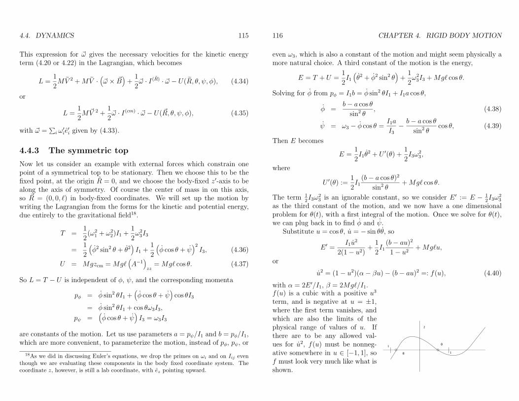
with α = 2E ′/I1, β = 2Mg`/I1.f(u) is a cubic with a positive u3
term, and is negative at u = ±1,where the first term vanishes, andwhich are also the limits of thephysical range of values of u. Ifthere are to be any allowed val-ues for u2, f(u) must be nonneg-ative somewhere in u ∈ [−1, 1], sof must look very much like what isshown.
2
θ
θ 1
1
4.4. DYNAMICS 117
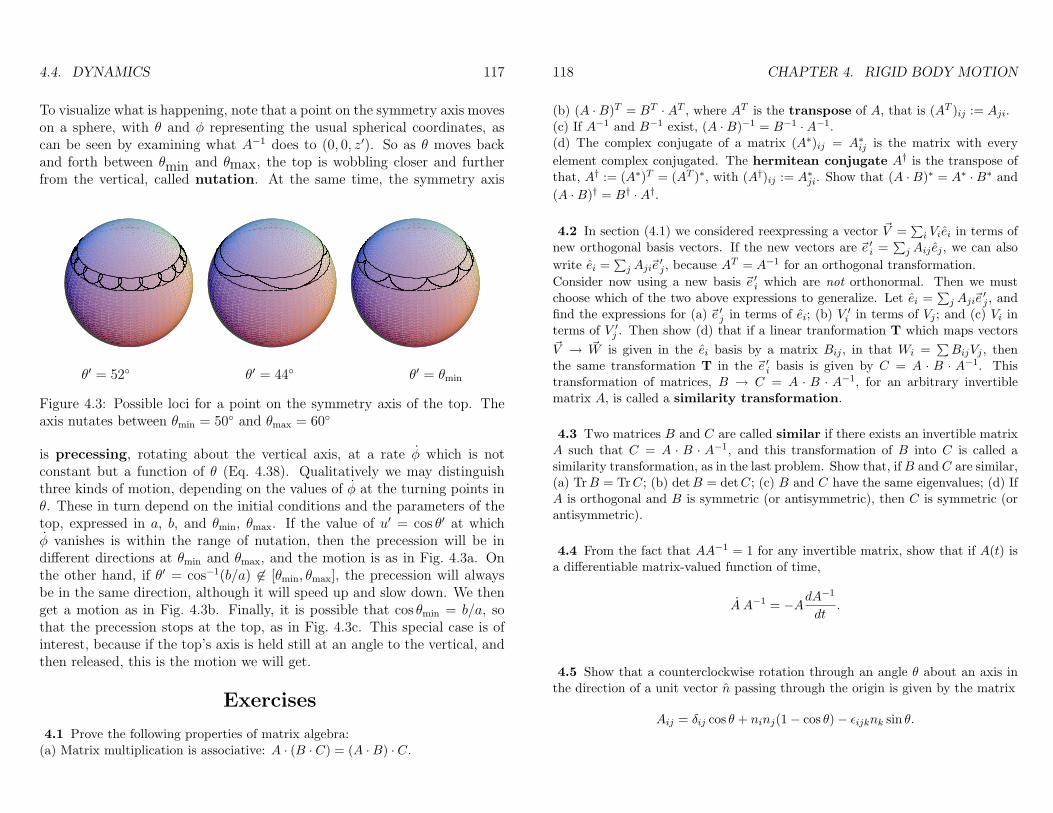
To visualize what is happening, note that a point on the symmetry axis moveson a sphere, with θ and φ representing the usual spherical coordinates, ascan be seen by examining what A−1 does to (0, 0, z′). So as θ moves backand forth between θmin and θmax, the top is wobbling closer and furtherfrom the vertical, called nutation. At the same time, the symmetry axis
θ′ = 52 θ′ = 44 θ′ = θmin
Figure 4.3: Possible loci for a point on the symmetry axis of the top. Theaxis nutates between θmin = 50 and θmax = 60
is precessing, rotating about the vertical axis, at a rate φ which is notconstant but a function of θ (Eq. 4.38). Qualitatively we may distinguishthree kinds of motion, depending on the values of φ at the turning points inθ. These in turn depend on the initial conditions and the parameters of thetop, expressed in a, b, and θmin, θmax. If the value of u′ = cos θ′ at whichφ vanishes is within the range of nutation, then the precession will be indifferent directions at θmin and θmax, and the motion is as in Fig. 4.3a. Onthe other hand, if θ′ = cos−1(b/a) 6∈ [θmin, θmax], the precession will alwaysbe in the same direction, although it will speed up and slow down. We thenget a motion as in Fig. 4.3b. Finally, it is possible that cos θmin = b/a, sothat the precession stops at the top, as in Fig. 4.3c. This special case is ofinterest, because if the top’s axis is held still at an angle to the vertical, andthen released, this is the motion we will get.
Exercises
4.1 Prove the following properties of matrix algebra:(a) Matrix multiplication is associative: A · (B · C) = (A ·B) · C.
118 CHAPTER 4. RIGID BODY MOTION
(b) (A ·B)T = BT ·AT , where AT is the transpose of A, that is (AT )ij := Aji.(c) If A−1 and B−1 exist, (A ·B)−1 = B−1 ·A−1.(d) The complex conjugate of a matrix (A∗)ij = A∗ij is the matrix with everyelement complex conjugated. The hermitean conjugate A† is the transpose ofthat, A† := (A∗)T = (AT )∗, with (A†)ij := A∗ji. Show that (A ·B)∗ = A∗ ·B∗ and(A ·B)† = B† ·A†.
4.2 In section (4.1) we considered reexpressing a vector ~V =∑i Viei in terms of
new orthogonal basis vectors. If the new vectors are ~e ′i =∑j Aij ej , we can also
write ei =∑j Aji~e
′j , because AT = A−1 for an orthogonal transformation.
Consider now using a new basis ~e ′i which are not orthonormal. Then we mustchoose which of the two above expressions to generalize. Let ei =
∑j Aji~e
′j , and
find the expressions for (a) ~e ′j in terms of ei; (b) V ′i in terms of Vj ; and (c) Vi interms of V ′j . Then show (d) that if a linear tranformation T which maps vectors~V → ~W is given in the ei basis by a matrix Bij , in that Wi =
∑BijVj , then
the same transformation T in the ~e ′i basis is given by C = A · B · A−1. Thistransformation of matrices, B → C = A · B · A−1, for an arbitrary invertiblematrix A, is called a similarity transformation.
4.3 Two matrices B and C are called similar if there exists an invertible matrixA such that C = A · B · A−1, and this transformation of B into C is called asimilarity transformation, as in the last problem. Show that, ifB and C are similar,(a) TrB = TrC; (b) detB = detC; (c) B and C have the same eigenvalues; (d) IfA is orthogonal and B is symmetric (or antisymmetric), then C is symmetric (orantisymmetric).
4.4 From the fact that AA−1 = 1 for any invertible matrix, show that if A(t) isa differentiable matrix-valued function of time,
A A−1 = −AdA−1
dt.
4.5 Show that a counterclockwise rotation through an angle θ about an axis inthe direction of a unit vector n passing through the origin is given by the matrix
Aij = δij cos θ + ninj(1− cos θ)− εijknk sin θ.
4.4. DYNAMICS 119
4.6 Consider a rigid body in the shape of a right circular cone of height h and abase which is a circle of radius R, made of matter with a uniform density ρ.a) Find the position of the center ofmass. Be sure to specify with respectto what.b) Find the moment of inertia ten-sor in some suitable, well specified co-ordinate system about the center ofmass.c) Initially the cone is spinning aboutits symmetry axis, which is in the zdirection, with angular velocity ω0,and with no external forces or torquesacting on it. At time t = 0 it is hitwith a momentary laser pulse whichimparts an impulse P in the x direc-tion at the apex of the cone, as shown.
R
h
P
y
x
Describe the subsequent force-free motion, including, as a function of time, theangular velocity, angular momentum, and the position of the apex, in any inertialcoordinate system you choose, provided you spell out the relation to the initialinertial coordinate system.
4.7 We defined the general rotation as A = Rz(ψ) · Ry(θ) · Rz(φ). Work outthe full expression for A(φ, θ, ψ), and verify the last expression in (4.31). [Forthis and exercise 4.8, you might want to use a computer algebra program such asmathematica or maple, if one is available.]
4.8 Find the expression for ~ω in terms of φ, θ, ψ, φ, θ, ψ. [This can be done simplywith computer algebra programs. If you want to do this by hand, you might findit easier to use the product form A = R3R2R1, and the rather simpler expressionsfor RRT . You will still need to bring the result (for R1R
T1 , for example) through
the other rotations, which is somewhat messy.]
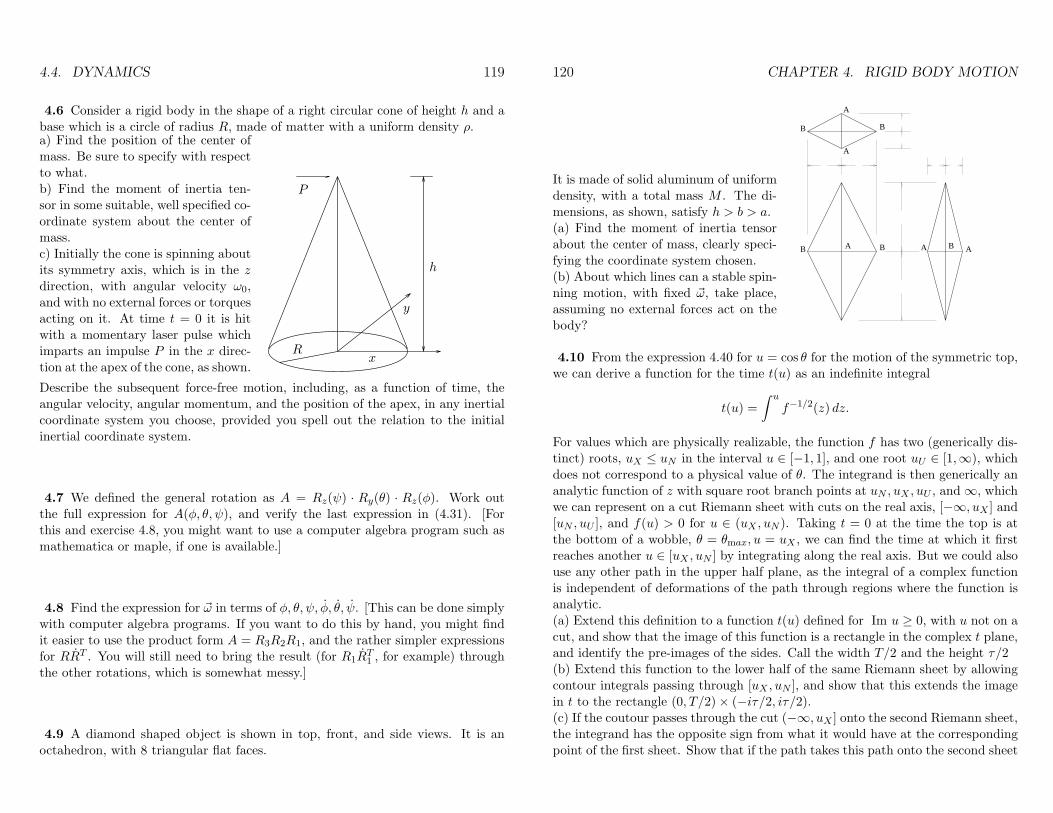
4.9 A diamond shaped object is shown in top, front, and side views. It is anoctahedron, with 8 triangular flat faces.
120 CHAPTER 4. RIGID BODY MOTION
It is made of solid aluminum of uniformdensity, with a total mass M . The di-mensions, as shown, satisfy h > b > a.(a) Find the moment of inertia tensorabout the center of mass, clearly speci-fying the coordinate system chosen.(b) About which lines can a stable spin-ning motion, with fixed ~ω, take place,assuming no external forces act on thebody?
B A B A B A
B B
A
A
4.10 From the expression 4.40 for u = cos θ for the motion of the symmetric top,we can derive a function for the time t(u) as an indefinite integral
t(u) =∫ u
f−1/2(z) dz.
For values which are physically realizable, the function f has two (generically dis-tinct) roots, uX ≤ uN in the interval u ∈ [−1, 1], and one root uU ∈ [1,∞), whichdoes not correspond to a physical value of θ. The integrand is then generically ananalytic function of z with square root branch points at uN , uX , uU , and ∞, whichwe can represent on a cut Riemann sheet with cuts on the real axis, [−∞, uX ] and[uN , uU ], and f(u) > 0 for u ∈ (uX , uN ). Taking t = 0 at the time the top is atthe bottom of a wobble, θ = θmax, u = uX , we can find the time at which it firstreaches another u ∈ [uX , uN ] by integrating along the real axis. But we could alsouse any other path in the upper half plane, as the integral of a complex functionis independent of deformations of the path through regions where the function isanalytic.(a) Extend this definition to a function t(u) defined for Im u ≥ 0, with u not on acut, and show that the image of this function is a rectangle in the complex t plane,and identify the pre-images of the sides. Call the width T/2 and the height τ/2(b) Extend this function to the lower half of the same Riemann sheet by allowingcontour integrals passing through [uX , uN ], and show that this extends the imagein t to the rectangle (0, T/2)× (−iτ/2, iτ/2).(c) If the coutour passes through the cut (−∞, uX ] onto the second Riemann sheet,the integrand has the opposite sign from what it would have at the correspondingpoint of the first sheet. Show that if the path takes this path onto the second sheet
4.4. DYNAMICS 121
and reaches the point u, the value t1(u) thus obtained is t1(u) = −t0(u), wheret0(u) is the value obtained in (a) or (b) for the same u on the first Riemann sheet.(d) Show that passing to the second Riemann sheet by going through the cut[uN , uU ] instead, produces a t2(u) = t1 + T .(e) Show that evaluating the integral along two contours, Γ1 and Γ2, which differonly by Γ1 circling the [uN , uU ] cut clockwise once more than Γ2 does, gives t1 =t2 + iτ .(f) Show that any value of t can be reached by some path, by circling the [uN , uU ]as many times as necessary, and also by passing downwards through it and upwardsthrough the [−∞, uX ] cut as often as necessary (perhaps reversed).(g) Argue that thus means the function u(t) is an analytic function from thecomplex t plane into the u complex plane, analytic except at the points t = nT +i(m+ 1
2)τ , where u(t) has double poles. Note this function is doubly periodic, withu(t) = u(t+ nT + imτ).(g) Show that the function is then given by u = β ℘(t − iτ/2) + c, where c is aconstant, β is the constant from (4.40), and
℘(z) =1z2
+∑
m,n∈ZZ(m,n) 6=0
(1
(z − nT −miτ)2− 1
(nT +miτ)2
)
is the Weierstrass’ ℘-Function.(h) Show that ℘ satisfies the differential equation
℘′2 = 4℘3 − g2℘− g3,
where
g2 =∑
m,n∈Z(m,n) 6=(0,0)
(mT + inτ)−4, g3 =∑
m,n∈Z(m,n) 6=(0,0)
(mT + inτ)−6.
[Note that the Weierstrass function is defined more generally, using parametersω1 = T/2, ω2 = iτ/2, with the ω’s permitted to be arbitrary complex numberswith differing phases.]
4.11 As a rotation about the origin maps the unit sphere into itself, one wayto describe rotations is as a subset of maps f : S2 → S2 of the (surface of the)unit sphere into itself. Those which correspond to rotations are clearly one-to-one, continuous, and preserve the angle between any two paths which intersectat a point. This is called a conformal map. In addition, rotations preserve thedistances between points. In this problem we show how to describe such mappings,and therefore give a representation for the rotations in three dimensions.
122 CHAPTER 4. RIGID BODY MOTION
(a) Let N be the north pole (0, 0, 1) of the unit sphere Σ = (x, y, z), x2+y2+z2 =1. Define the map from the rest of the sphere s : Σ − N → R
2 given by astereographic projection, which maps each point on the unit sphere, other thanthe north pole, into the point (u, v) in the equatorial plane (x, y, 0) by giving theintersection with this plane of the straight line which joins the point (x, y, z) ∈ Σto the north pole. Find (u, v) as a function of (x, y, z), and show that the lengthsof infinitesimal paths in the vicinity of a point are scaled by a factor 1/(1 − z)independent of direction, and therefore that the map s preserves the angles betweenintersecting curves (i.e. is conformal).(b) Show that the map f((u, v)) → (u′, v′) which results from first applying s−1,then a rotation, and then s, is a conformal map from R
2 into R2, except for the
pre-image of the point which gets mapped into the north pole by the rotation.By a general theorem of complex variables, any such map is analytic, so f : u+iv →u′ + iv′ is an analytic function except at the point ξ0 = u0 + iv0 which is mappedto infinity, and ξ0 is a simple pole of f . Show that f(ξ) = (aξ + b)/(ξ − ξ0), forsome complex a and b. This is the set of complex Mobius transformations, whichare usually rewritten as
f(ξ) =αξ + β
γξ + δ,
where α, β, γ, δ are complex constants. An overall complex scale change does notaffect f , so the scale of these four complex constants is generally fixed by imposinga normalizing condition αδ − βγ = 1.(c) Show that composition of Mobius transformations f ′′ = f ′ f : ξ −→
fξ′ −→
f ′ξ′′
is given by matrix multiplication,(α′′ β′′
γ′′ δ′′)
=(α′ β′
γ′ δ′)·(α βγ δ
).
(d) Not every mapping s−1 f s is a rotation, for rotations need to preservedistances as well. We saw that an infinitesimal distance d` on Σ is mapped by s toa distance |dξ| = d`/(1− z). Argue that the condition that f : ξ → ξ correspondto a rotation is that d˜≡ (1 − z)|df/dξ||dξ| = d`. Express this change of scale interms of ξ and ξ rather than z and z, and find the conditions on α, β, γ, δ thatinsure this is true for all ξ. Together with the normalizing condition, show that thisrequires the matrix for f to be a unitary matrix with determinant 1, so that theset of rotations corresponds to the group SU(2). The matrix elements are calledCayley-Klein parameters, and the real and imaginary parts of them are called theEuler parameters.