
30RBS 039-160/30RQS 039-160 - AHI Carrier Ν.Α ... · PRODUCT SELECTION DATA Air-Cooled Liquid...
26
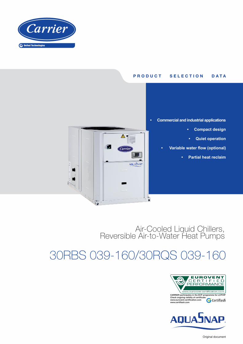
PRODUCT SELECTION DATA Air-Cooled Liquid Chillers, Reversible Air-to-Water Heat Pumps 30RBS 039-160/30RQS 039-160 Original document • Commercial and industrial applications • Compact design • Quiet operation • Variable water flow (optional) • Partial heat reclaim CARRIER participates in the ECP programme for LCP/HP Check ongoing validity of certificate: www.eurovent-certification.com www.certiflash.com
Transcript of 30RBS 039-160/30RQS 039-160 - AHI Carrier Ν.Α ... · PRODUCT SELECTION DATA Air-Cooled Liquid...
P R O D U C T S E L E C T I O N D A T A
Air-Cooled Liquid Chillers, Reversible Air-to-Water Heat Pumps
30RBS 039-160/30RQS 039-160
Original document
• Commercial and industrial applications
• Compact design
• Quiet operation
• Variable water flow (optional)
• Partial heat reclaim
CARRIER participates in the ECP programme for LCP/HPCheck ongoing validity of certificate:www.eurovent-certification.com www.certiflash.com
2
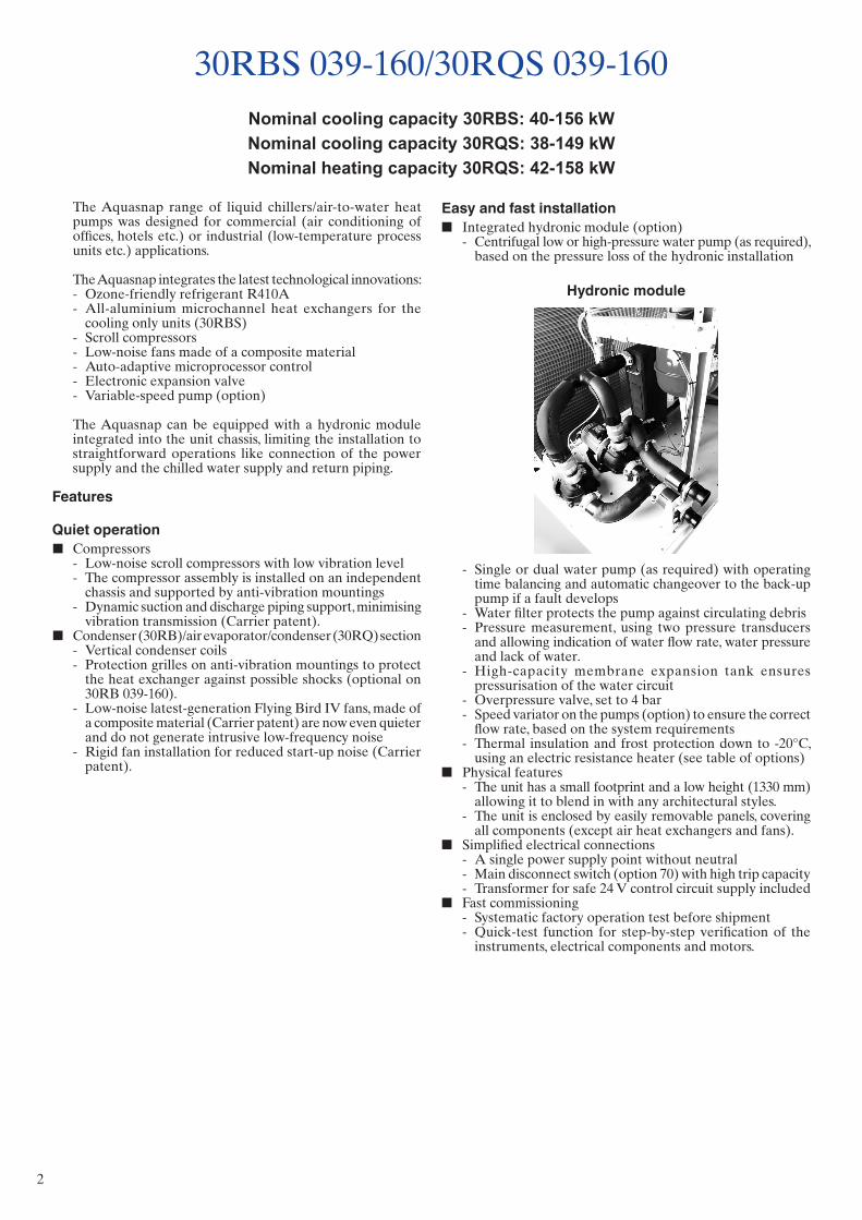
Easy and fast installation ■ Integrated hydronic module (option)
- Centrifugal low or high-pressure water pump (as required), based on the pressure loss of the hydronic installation
Hydronic module
- Single or dual water pump (as required) with operating time balancing and automatic changeover to the back-up pump if a fault develops
- Water filter protects the pump against circulating debris - Pressure measurement, using two pressure transducers
and allowing indication of water flow rate, water pressure and lack of water.
- High-capacity membrane expansion tank ensures pressurisation of the water circuit
- Overpressure valve, set to 4 bar - Speed variator on the pumps (option) to ensure the correct
flow rate, based on the system requirements - Thermal insulation and frost protection down to -20°C,
using an electric resistance heater (see table of options) ■ Physical features
- The unit has a small footprint and a low height (1330 mm) allowing it to blend in with any architectural styles.
- The unit is enclosed by easily removable panels, covering all components (except air heat exchangers and fans).
■ Simplified electrical connections - A single power supply point without neutral - Main disconnect switch (option 70) with high trip capacity - Transformer for safe 24 V control circuit supply included
■ Fast commissioning - Systematic factory operation test before shipment - Quick-test function for step-by-step verification of the
instruments, electrical components and motors.
The Aquasnap range of liquid chillers/air-to-water heat pumps was designed for commercial (air conditioning of offices, hotels etc.) or industrial (low-temperature process units etc.) applications.
The Aquasnap integrates the latest technologi cal innovations: - Ozone-friendly refrigerant R410A - All-aluminium microchannel heat exchangers for the
cooling only units (30RBS) - Scroll compressors - Low-noise fans made of a composite material - Auto-adaptive microprocessor control - Electronic expansion valve - Variable-speed pump (option)
The Aquasnap can be equipped with a hydronic module integrated into the unit chassis, limiting the installation to straightforward operations like connection of the power supply and the chilled water supply and return piping.
Features
Quiet operation ■ Compressors
- Low-noise scroll compressors with low vibration level - The compressor assembly is installed on an independent
chassis and supported by anti-vibration mountings - Dynamic suction and discharge piping support, minimising
vibration transmission (Carrier patent). ■ Condenser (30RB)/air evaporator/condenser (30RQ) section
- Vertical condenser coils - Protection grilles on anti-vibration mountings to protect
the heat exchanger against possible shocks (optional on 30RB 039-160).
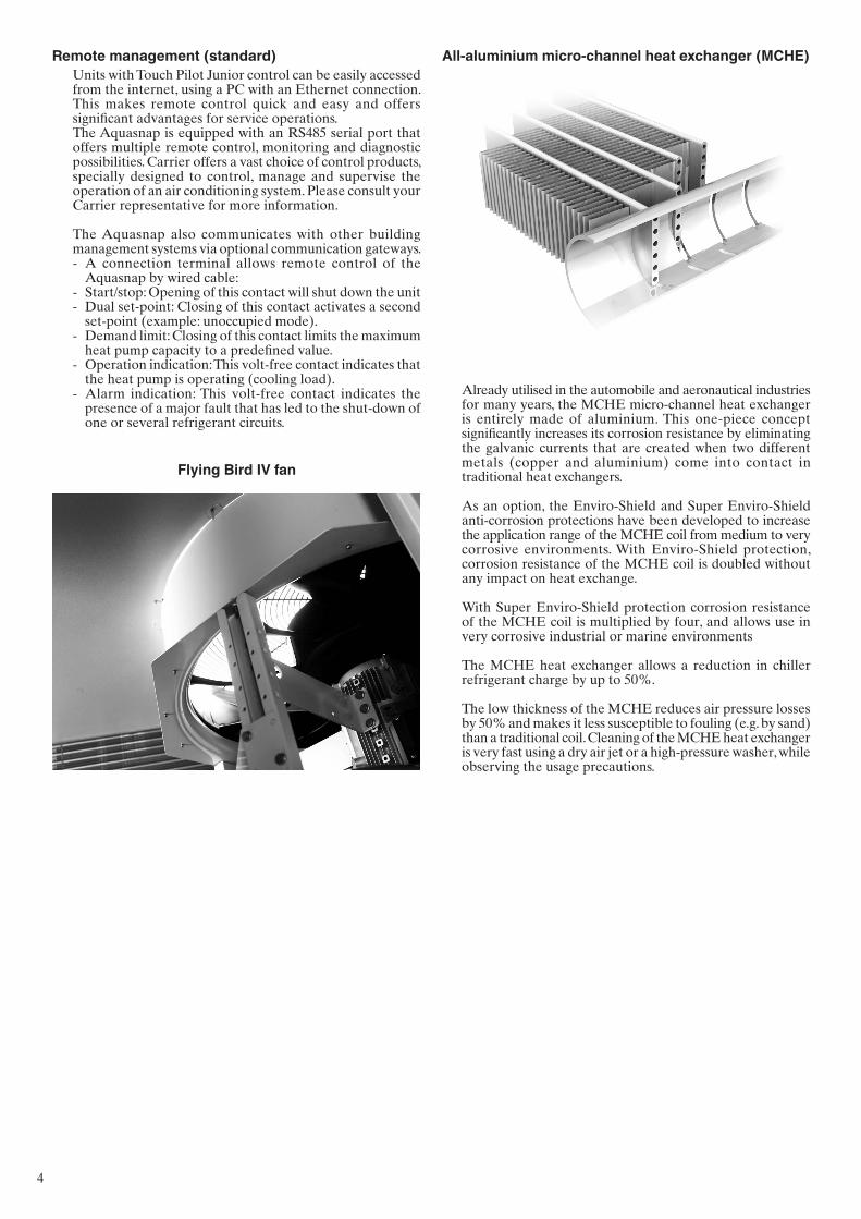
- Low-noise latest-generation Flying Bird IV fans, made of a composite material (Carrier patent) are now even quieter and do not generate intrusive low-frequency noise
- Rigid fan installation for reduced start-up noise (Carrier patent).
30RBS 039-160/30RQS 039-160Nominal cooling capacity 30RBS: 40-156 kWNominal cooling capacity 30RQS: 38-149 kWNominal heating capacity 30RQS: 42-158 kW
3
■ Auto-adaptive control - Control algorithm prevents excessive compressor cycling
and permits reduction of the water quantity in the hydronic circuit (Carrier patent)
- Hydronic module with integrated pressure transducers allowing measurement of the water pressure at two points, as well as measurement of the water flow rate and detection of lack of water and pressure. This considerably reduces the risk of problems such as frost accumulation on the water heat exchanger.
- Automatic compressor unloading in case of abnormally high condensing pressure. If an anomaly occurs (e.g. fouled air heat exchanger coil, fan failure) Aquasnap continues to operate, but at reduced capacity.
■ Exceptional endurance tests - Corrosion resistance tests in salt mist in the laboratory - Accelerated ageing test on components that are submitted
to continuous operation: compressor piping, fan supports - Transport simulation test in the laboratory on a vibrating
table.
Touch Pilot Junior controlThe Touch Pilot Junior features a control with advanced communication technology over Ethernet (IP), user-friendly and intuitive user interface with 4.3” colour touch screen.
■ Energy management - Internal time schedule clock: Controls heat pump on/off times
and operation at a second set-point - Set-point offset based on the outside air temperature - Master/slave control of two heat pumps operating in parallel
with operating time equalisation and automatic change-over in case of a unit fault.
■ Integrated advanced communication features - Night mode: Capacity and fan speed limitation for reduced
noise level - With hydronic module: Water pressure display and water
flow rate calculation - Easy and high-speed communication technology over
Ethernet (IP) to a building management system - Access to multiple unit parameters.
■ 4.3" Touch Pilot Junior user interface
- Intuitive and user-friendly 4.3 inch touch screen interface - Concise and clear information is available in local languages - Complete menu, customised for different users (end user,
service personnel or Carrier engineers).
Economical operation - Optional variable-speed pump for economical operation - The control algorithm adjusts the water flow rate based
on the actual system requirements and obsoletes the need for the control valve at the unit outlet.
■ Increased energy efficiency at part load - Eurovent energy efficiency class (in accordance with
EN14511-3:2013) C and D in cooling mode and B and C in heating mode.
- The refrigerant circuit includes several compressors connected in parallel. At part load, around 99% of the operating time, only the compressors that are absolutely necessary operate. At these conditions the compressors operating are more energy efficient, as they use the total condenser and evaporator capacity.
- The electronic expansion device (EXV) allows operation at a lower condensing pressure (EER, COP and ESEER, SCOP optimisation).
- Dynamic superheat management for better utilisation of the water heat exchanger surface.
- Defrost cycle optimisation (30RQ). ■ Reduced maintenance costs
- Maintenance-free scroll compressors - Fast diagnosis of possible incidents and their history via
the Touch Pilot Junior control - R410A refrigerant is easier to use than other refrigerant
blends.
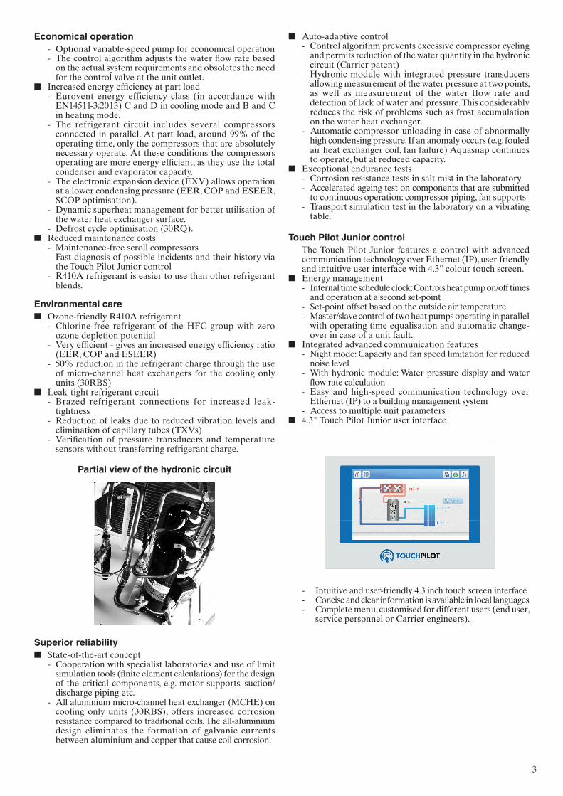
Environmental care ■ Ozone-friendly R410A refrigerant
- Chlorine-free refrigerant of the HFC group with zero ozone depletion potential
- Very efficient - gives an increased energy efficiency ratio (EER, COP and ESEER)
- 50% reduction in the refrigerant charge through the use of micro-channel heat exchangers for the cooling only units (30RBS)
■ Leak-tight refrigerant circuit - Brazed refrigerant connections for increased leak-
tightness - Reduction of leaks due to reduced vibration levels and
elimination of capillary tubes (TXVs) - Verification of pressure transducers and temperature
sensors without transferring refrigerant charge.
Partial view of the hydronic circuit
Superior reliability ■ State-of-the-art concept
- Cooperation with specialist laboratories and use of limit simulation tools (finite element calculations) for the design of the critical components, e.g. motor supports, suction/discharge piping etc.
- All aluminium micro-channel heat exchanger (MCHE) on cooling only units (30RBS), offers increased corrosion resistance compared to traditional coils. The all-aluminium design eliminates the formation of galvanic currents between aluminium and copper that cause coil corrosion.
4
Flying Bird IV fan
All-aluminium micro-channel heat exchanger (MCHE)
Already utilised in the automobile and aeronautical industries for many years, the MCHE micro-channel heat exchanger is entirely made of aluminium. This one-piece concept significantly increases its corrosion resistance by eliminating the galvanic currents that are created when two different metals (copper and aluminium) come into contact in traditional heat exchangers.
As an option, the Enviro-Shield and Super Enviro-Shield anti-corrosion protections have been developed to increase the application range of the MCHE coil from medium to very corrosive environments. With Enviro-Shield protection, corrosion resistance of the MCHE coil is doubled without any impact on heat exchange.
With Super Enviro-Shield protection corrosion resistance of the MCHE coil is multiplied by four, and allows use in very corrosive industrial or marine environments
The MCHE heat exchanger allows a reduction in chiller refrigerant charge by up to 50%.
The low thickness of the MCHE reduces air pressure losses by 50% and makes it less susceptible to fouling (e.g. by sand) than a traditional coil. Cleaning of the MCHE heat exchanger is very fast using a dry air jet or a high-pressure washer, while observing the usage precautions.
Remote management (standard)Units with Touch Pilot Junior control can be easily accessed from the internet, using a PC with an Ethernet connection. This makes remote control quick and easy and offers significant advantages for service operations.The Aquasnap is equipped with an RS485 serial port that offers multiple remote control, monitoring and diagnostic possibilities. Carrier offers a vast choice of control products, specially designed to control, manage and supervise the operation of an air conditioning system. Please consult your Carrier representative for more information.
The Aquasnap also communicates with other building management systems via optional communication gateways. - A connection terminal allows remote control of the
Aquasnap by wired cable: - Start/stop: Opening of this contact will shut down the unit - Dual set-point: Closing of this contact activates a second
set-point (example: unoccupied mode). - Demand limit: Closing of this contact limits the maximum
heat pump capacity to a predefined value. - Operation indication: This volt-free contact indicates that
the heat pump is operating (cooling load). - Alarm indication: This volt-free contact indicates the
presence of a major fault that has led to the shut-down of one or several refrigerant circuits.
5
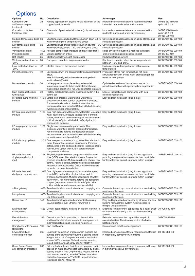
OptionsOptions No. Description Advantages UseCondenser with anti6corrosion post treatment
2B Factory application of Blygold Polual treatment on the copper/aluminium coils
Improved corrosion resistance, recommended for industrial, rural and marine environments
30RBS 039-160 with option 49, 5 or 6
Corrosion protection, traditional coils
3A Fins made of pre-treated aluminium (polyurethane and epoxy)
Improved corrosion resistance, recommended for moderate marine and urban environments
30RBS 039-160 with option 49, 5 or 630RQS 039-160
Medium-temperature brine solution
5B Low temperature chilled water production down to 0°C with ethylene glycol and propylene glycol.
Covers specific applications such as ice storage and industrial processes
30RBS/ 30RQS 039-160
Low-temperature brine solution
6B Low temperature chilled water production down to -15°C with ethylene glycol and -12°C with propylene glycol.
Covers specific applications such as ice storage and industrial processes
30RBS/ 30RQS 039-160
Very low noise level 15LS Acoustic compressor enclosure and low-speed fans Noise emission reduction at reduces fan speed 30RBS/ 30RQS 039-160Protection grilles 23 Metallic protection grilles Coil protection against possible impact 30RBS 039-160Soft Starter 25 Electronic starter on each compressor Reduced start-up current 30RBS/ 30RQS 039-160Winter operation down to -20°C
28 Fan speed control via frequency converter Stable unit operation when the air temperature is between -10°C and -20°C.
30RBS/ 30RQS 039-160
Frost protection down to -20°C
42 Electric heater on the hydronic module Hydronic module frost protection at low outside temperatures
30RBS/ 30RQS 039-160
Partial heat recovery 49 Unit equipped with one desuperheater on each refrigerant circuit.Note: In this configuration the units are equipped with traditional coils (Cu/Al).
Production of free high-temperature hot-water simultaneously with chilled water production (or hot water for Heat pump)
30RBS/ 30RQS 039-160
Master/slave operation 58 Unit equipped with supplementary water outlet temperature sensor kit to be field-installed allowing master/slave operation of two units connected in parallel
Optimised operation of two units connected in parrallele operation with operating time equalisation
30RBS/ 30RQS 039-160
Main disconnect switch without fuse
70 Factory-installed main electric disconnect switch in the control box
Ease-of-installation and compliance with local electrical regulations
30RBS/ 30RQS 039-160
HP single-pump hydronic module
116R Single high-pressure water pump, water filter, electronic water flow control, pressure transducers. For more details, refer to the dedicated chapter (expansion tank not included.Option with built-in safety hydraulic components available.)
Easy and fast installation (plug & play) 30RBS/ 30RQS 039-160
HP dual-pump hydronic module
116S Dual high-pressure water pump, water filter, electronic water flow control, pressure transducers. For more details, refer to the dedicated chapter (expansion tank not included) Option with built-in safety hydraulic components available)
Easy and fast installation (plug & play) 30RBS/ 30RQS 039-160
LP single-pump hydronic module
116T Single low-pressure water pump, water filter, electronic water flow control, pressure transducers. For more details, refer to the dedicated chapter (expansion tank not included Option with built-in safety hydraulic components available)
Easy and fast installation (plug & play) 30RBS/ 30RQS 039-160
LP dual-pump hydronic module
116U Dual low-pressure water pump, water filter, electronic water flow control, pressure transducers. For more details, refer to the dedicated chapter (expansion tank not included Option with built-in safety hydraulic components available)
Easy and fast installation (plug & play) 30RBS/ 30RQS 039-160
HP variable-speed single-pump hydronic mod.
116V Single high-pressure water pump with variable speed drive (VSD), water filter, electronic water flow control, pressure transducers. Multiple possibilities of water flow control. For more details, refer to the dedicated chapter (expansion tank not included Option with built-in safety hydraulic components available)
Easy and fast installation (plug & play), significant pumping energy cost savings (more than two-thirds), tighter water flow control, improved sytem reliability
30RBS/ 30RQS 039-160
HP variable-speed dual-pump hydronic mod.
116W Dual high-pressure water pump with variable speed drive (VSD), water filter, electronic flow switch, pressure transducers. Multiple possibilities of water flow control. For more details, refer to the dedicated chapter (expansion tank not included Option with built-in safety hydraulic components available)
Easy and fast installation (plug & play), significant pumping energy cost savings (more than two-thirds), tighter water flow control, improved sytem reliability
30RBS/ 30RQS 039-160
J-Bus gateway 148B Two-directional communication board complying with JBus protocol
Connects the unit by communication bus to a building management system
30RBS/ 30RQS 039-160
Lon gateway 148D Two-directional communication board complying with Lon Talk protocol
Connects the unit by communication bus to a building management system
30RBS/ 30RQS 039-160
Bacnet over IP 149 Two-directional high-speed communication using BACnet protocol over Ethernet network (IP)
Easy and high-speed connection by ethernet line to a building management system. Allows access to multiple unit parameters
30RBS/ 30RQS 039-160
External boiler management
156a Control board factory-installed on the unit to control a boiler
Extended remote control capabilities to a boiler on/off command.Permits easy control of a basic heating system
30RQS 039-160
Electric heaters management
156b Control board factory-installed on the unit with additional inputs/outputs in order to manage up to 4 externals heating stage (electrical heaters…)
Extended remote control capabilities to up to 4 electrics heaters. Permits easy control of a basic heating system
30RQS 039-160
Compliance with Russian regulations
199 EAC certification Conformance with Russian regulations 30RBS/ 30RQS 039-160
Enviro-Shield anti-corrosion protection
262 Coating by conversion process which modifies the surface of the aluminum producing a coating that is integral to the coil. Complete immersion in a bath to ensure 100% coverage. No heat transfer variation, tested 4000 hours salt spray per ASTM B117
Improved corrosion resistance, recommended for use in moderately corrosive environments
30RBS 039-160
Super Enviro-Shield anti-corrosion protection
263 Extremely durable and flexible epoxy polymer coating applied on micro channel heat exchangers by electro coating process, final UV protective topcoat. Minimal heat transfer variation, tested 6000 hours constant neutral salt spray per ASTM B117, superior impact resistance per ASTM D2794
Improved corrosion resistance, recommended for use in extremely corrosive environments
30RBS 039-160
6
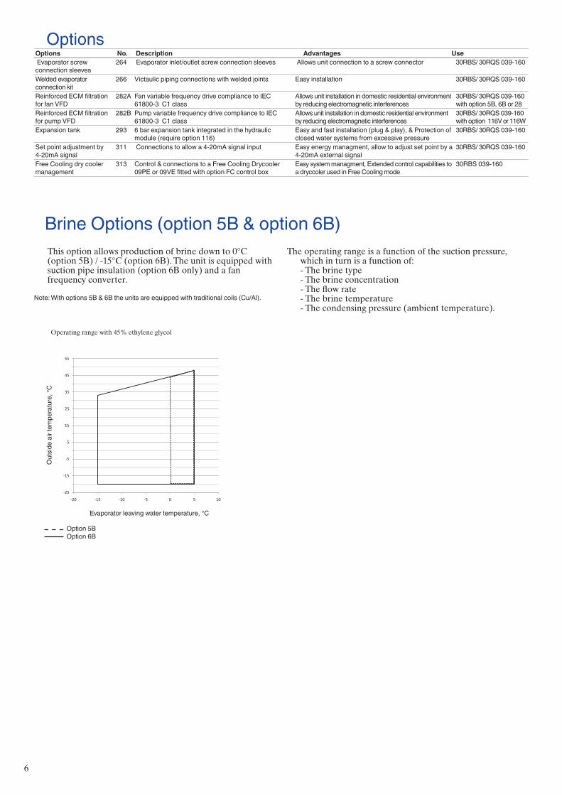
Brine Options (option 5B & option 6B)This option allows production of brine down to 0°C(option 5B) / -15°C (option 6B). The unit is equipped withsuction pipe insulation (option 6B only) and a fanfrequency converter.
Note: With options 5B & 6B the units are equipped with traditional coils (Cu/Al).
The operating range is a function of the suction pressure, which in turn is a function of:- The brine type- The brine concentration- The flow rate- The brine temperature- The condensing pressure (ambient temperature).
Operating range with 45% ethylene glycol Operating range with 45% ethylene glycol
Out
side
air
tem
pera
ture
, °C
Evaporator leaving water temperature, °C
Option 5B Option 6B
-25
-15
-5
5
15
25
35
45
55
-20 -15 -10 -5 0 5 10
Out
side
air
tem
pera
ture
, °C
Evaporator leaving water temperature, °C
Option 5B Option 6B
Evaporator screw connection sleeves
264 Evaporator inlet/outlet screw connection sleeves Allows unit connection to a screw connector 30RBS/ 30RQS 039-160
Welded evaporator connection kit
266 Victaulic piping connections with welded joints Easy installation 30RBS/ 30RQS 039-160
Reinforced ECM filtration for fan VFD
282A Fan variable frequency drive compliance to IEC 61800-3 C1 class
Allows unit installation in domestic residential environment by reducing electromagnetic interferences
30RBS/ 30RQS 039-160 with option 5B, 6B or 28
Reinforced ECM filtration for pump VFD
282B Pump variable frequency drive compliance to IEC 61800-3 C1 class
Allows unit installation in domestic residential environment by reducing electromagnetic interferences
30RBS/ 30RQS 039-160 with option 116V or 116W
Expansion tank 293 6 bar expansion tank integrated in the hydraulic module (require option 116)
Easy and fast installation (plug & play), & Protection of closed water systems from excessive pressure
30RBS/ 30RQS 039-160
Set point adjustment by 4-20mA signal
311 Connections to allow a 4-20mA signal input Easy energy managment, allow to adjust set point by a 4-20mA external signal
30RBS/ 30RQS 039-160
Free Cooling dry cooler management
313 Control & connections to a Free Cooling Drycooler 09PE or 09VE fitted with option FC control box
Easy system managment, Extended control capabilities to a dryccoler used in Free Cooling mode
30RBS 039-160
OptionsOptions No. Description Advantages Use
7
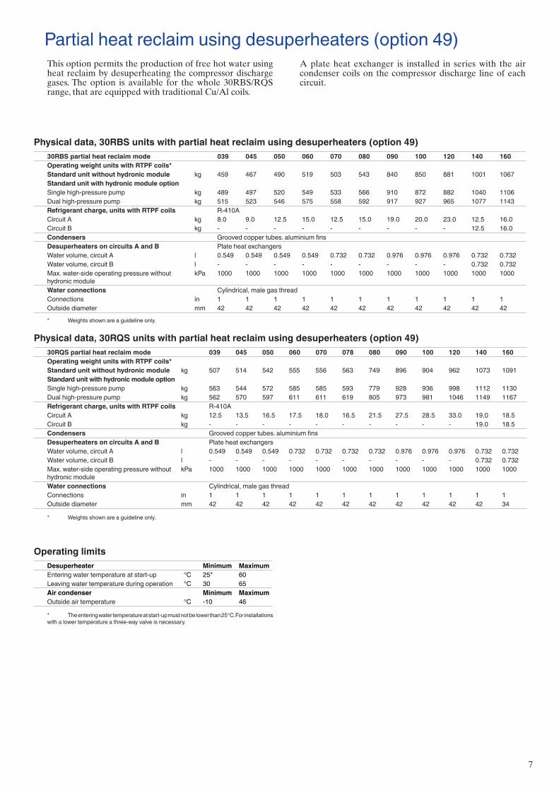
Physical data, 30RBS units with partial heat reclaim using desuperheaters (option 49)30RBS partial heat reclaim mode 039 045 050 060 070 080 090 100 120 140 160Operating weight units with RTPF coils*Standard unit without hydronic module kg 459 467 490 519 503 543 840 850 881 1001 1067Standard unit with hydronic module optionSingle high-pressure pump kg 489 497 520 549 533 566 910 872 882 1040 1106Dual high-pressure pump kg 515 523 546 575 558 592 917 927 965 1077 1143Refrigerant charge, units with RTPF coils R-410ACircuit A kg 8.0 9.0 12.5 15.0 12.5 15.0 19.0 20.0 23.0 12.5 16.0Circuit B kg - - - - - - - - - 12.5 16.0Condensers Grooved copper tubes. aluminium finsDesuperheaters on circuits A and B Plate heat exchangersWater volume, circuit A l 0.549 0.549 0.549 0.549 0.732 0.732 0.976 0.976 0.976 0.732 0.732Water volume, circuit B l - - - - - - - - - 0.732 0.732Max. water-side operating pressure without hydronic module
kPa 1000 1000 1000 1000 1000 1000 1000 1000 1000 1000 1000
Water connections Cylindrical, male gas threadConnections in 1 1 1 1 1 1 1 1 1 1 1Outside diameter mm 42 42 42 42 42 42 42 42 42 42 42
* Weights shown are a guideline only.
Physical data, 30RQS units with partial heat reclaim using desuperheaters (option 49)30RQS partial heat reclaim mode 039 045 050 060 070 078 080 090 100 120 140 160Operating weight units with RTPF coils*Standard unit without hydronic module kg 507 514 542 555 556 563 749 896 904 962 1073 1091Standard unit with hydronic module optionSingle high-pressure pump kg 563 544 572 585 585 593 779 928 936 998 1112 1130Dual high-pressure pump kg 562 570 597 611 611 619 805 973 981 1046 1149 1167Refrigerant charge, units with RTPF coils R-410ACircuit A kg 12.5 13.5 16.5 17.5 18.0 16.5 21.5 27.5 28.5 33.0 19.0 18.5Circuit B kg - - - - - - - - - - 19.0 18.5Condensers Grooved copper tubes. aluminium finsDesuperheaters on circuits A and B Plate heat exchangersWater volume, circuit A l 0.549 0.549 0.549 0.732 0.732 0.732 0.732 0.976 0.976 0.976 0.732 0.732Water volume, circuit B l - - - - - - - - - - 0.732 0.732Max. water-side operating pressure without hydronic module
kPa 1000 1000 1000 1000 1000 1000 1000 1000 1000 1000 1000 1000
Water connections Cylindrical, male gas threadConnections in 1 1 1 1 1 1 1 1 1 1 1 1Outside diameter mm 42 42 42 42 42 42 42 42 42 42 42 34
* Weights shown are a guideline only.
Partial heat reclaim using desuperheaters (option 49)This option permits the production of free hot water using heat reclaim by desuperheating the compressor discharge gases. The option is available for the whole 30RBS/RQS range, that are equipped with traditional Cu/Al coils.
A plate heat exchanger is installed in series with the air condenser coils on the compressor discharge line of each circuit.
Operating limitsDesuperheater Minimum MaximumEntering water temperature at start-up °C 25* 60Leaving water temperature during operation °C 30 65Air condenser Minimum MaximumOutside air temperature °C -10 46
* The entering water temperature at start-up must not be lower than 25°C. For installations with a lower temperature a three-way valve is necessary.
8
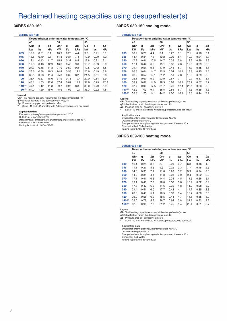
Reclaimed heating capacities using desuperheater(s)30RBS 039-160
30RBS 039-160Desuperheater entering water temperature, °C45 50 55Qhr q Δp Qhr q Δp Qc q ΔpkW l/s kPa kW l/s kPa kW l/s kPa
039 12.9 0.31 6.1 10.9 0.26 4.4 9.0 0.21 3.1045 16.5 0.40 9.5 14.3 0.34 7.4 12.0 0.29 5.2050 18.1 0.43 11.7 15.4 0.37 8.5 12.8 0.31 6.1060 19.3 0.46 12.9 16.6 0.40 9.8 13.7 0.33 6.9070 24.3 0.58 11.8 21.0 0.50 9.2 17.5 0.42 6.5080 28.6 0.68 16.3 24.4 0.58 12.1 20.6 0.49 8.8090 30.5 0.73 11.4 25.8 0.62 8.2 21.5 0.51 5.8100 36.4 0.87 16.0 31.9 0.76 12.4 27.0 0.64 8.9120 43.1 1.03 22.6 37.4 0.89 17.2 31.6 0.75 12.3140 (1) 47.1 1.12 11.3 39.7 0.95 8.3 33.0 0.79 5.9160 (1) 54.0 1.29 15.0 45.6 1.09 10.7 38.3 0.92 7.8
Legend Qhr Total heating capacity reclaimed at the desuperheater(s), kW q Total water flow rate in the desuperheater loop, l/s Δp Pressure drop per desuperheater, kPa (1) Sizes 140 and 160 are fitted with 2 desuperheaters, one per circuit.
Application data Evaporator entering/leaving water temperature 12/7°C Outside air temperature 35°C Desuperheater entering/leaving water temperature difference 10 K Evaporator fluid: Chilled water Fouling factor 0.18 x 10⁻⁴ (m2 K)/W
30RQS 039-160 cooling mode
30RQS 039-160Desuperheater entering water temperature, °C45 50 55Qhr q Δp Qhr q Δp Qc q ΔpkW l/s kPa kW l/s kPa kW l/s kPa
039 10.9 0.26 4.4 9.1 0.22 3.1 7.1 0.18 2.1045 14.4 0.34 7.5 12.2 0.29 5.4 10.0 0.24 3.7050 17.2 0.41 10.5 14.7 0.35 7.8 12.3 0.29 5.6060 17.4 0.44 6.6 15.1 0.36 4.6 12.3 0.29 3.0070 21.4 0.51 9.3 17.9 0.43 6.7 14.7 0.35 4.8078 26.8 0.64 14.7 22.5 0.54 10.4 18.8 0.45 7.5080 23.9 0.57 12.1 21.2 0.51 7.8 16.3 0.39 5.8090 28.1 0.67 9.9 23.9 0.57 7.1 19.7 0.47 5.1100 33.9 0.81 14.0 28.3 0.68 10.1 23.7 0.57 7.2120 37.7 0.90 17.5 31.7 0.76 12.4 26.5 0.63 8.9140 (1) 42.9 1.03 9.4 35.5 0.85 6.7 14.5 0.35 4.5160 (1) 52.3 1.25 14.1 44.2 1.06 10.1 18.3 0.44 7.1
Legend Qhr Total heating capacity reclaimed at the desuperheater(s), kW q Total water flow rate in the desuperheater loop, l/s Δp Pressure drop per desuperheater, kPa (1) Sizes 140 and 160 are fitted with 2 desuperheaters, one per circuit.
Application data Evaporator entering/leaving water temperature 12/7°C Outside air temperature 35°C Desuperheater entering/leaving water temperature difference 10 K Evaporator fluid: Chilled water Fouling factor 0.18 x 10⁻⁴ (m2 K)/W
30RQS 039-160 heating mode
30RQS 039-160Desuperheater entering water temperature, °C45 50 55Qhr q Δp Qhr q Δp Qc q ΔpkW l/s kPa kW l/s kPa kW l/s kPa
039 10.1 0.24 3.8 8.3 0.20 2.7 6.8 0.16 1.8045 11.1 0.27 4.6 9.3 0.22 3.3 7.7 0.18 2.3050 14.0 0.33 7.1 11.8 0.28 5.2 9.9 0.24 3.6060 14.3 0.34 4.4 11.8 0.28 3.0 9.4 0.22 2.0070 17.1 0.41 6.3 14.4 0.34 4.5 11.9 0.28 3.1078 19.1 0.46 7.8 16.0 0.38 5.6 13.2 0.32 3.9080 17.5 0.42 6.6 14.6 0.35 4.8 11.7 0.28 3.2090 21.4 0.51 6.0 17.7 0.42 4.1 14.7 0.35 2.8100 20.6 0.49 5.1 16.5 0.39 3.4 12.7 0.30 2.0120 23.0 0.55 6.9 18.5 0.44 4.7 14.5 0.35 3.0140 (1) 32.0 0.77 5.5 26.7 0.64 3.8 21.6 0.52 2.6160 (1) 37.5 0.90 7.3 31.2 0.75 5.4 25.4 0.61 3.7
Legend Qhr Total heating capacity reclaimed at the desuperheater(s), kW q Total water flow rate in the desuperheater loop, l/s Δp Pressure drop per desuperheater, kPa (1) Sizes 140 and 160 are fitted with 2 desuperheaters, one per circuit.
Application data Evaporator entering/leaving water temperature 40/45°C Outside air temperature 7°C Desuperheater entering/leaving water temperature difference 10 K Condenser fluid: Water Fouling factor 0.18 x 10⁻⁴ (m2 K)/W
9
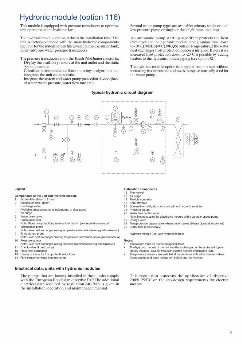
Hydronic module (option 116)This module is equipped with pressure transducers to optimise unit operation at the hydronic level.
The hydronic module option reduces the installation time. The unit is factory-equipped with the main hydronic compo-nents required for the system: screen filter, water pump, expansion tank, relief valve and water pressure transducers.
The pressure transducers allow the Touch Pilot Junior control to: - Display the available pressure at the unit outlet and the static
system pressure - Calculate the instantaneous flow rate, using an algorithm that
integrates the unit characteristics - Integrate the system and water pump protection devices (lack
of water, water pressure, water flow rate etc.)
Several water pump types are available: primary single or dual low-pressure pump or single or dual high-pressure pump.
An automatic pump start-up algorithm protects the heat exchanger and the hydronic module piping against frost down to -10°C(30RBS)/0°C(30RQS) outside temperature, if the water heat exchanger frost protection option is installed. If necessary increased frost protection down to -20°C is possible by adding heaters to the hydronic module piping (see option 42).
The hydronic module option is integrated into the unit without increasing its dimensions and saves the space normally used for the water pump.
Electrical data, units with hydronic modulesThe pumps that are factory-installed in these units comply with the European Ecodesign directive ErP. The additional electrical data required by regulation 640/2009 is given in the installation, operation and maintenance manual.
This regulation concerns the application of directive 2009/125/EC on the eco-design requirements for electric motors.
Typical hydronic circuit diagram
Legend
Components of the unit and hydronic module1 Screen filter (Mesh1.2 mm)2 Expansion tank (option)3 Discharge valve4 Available pressure pump (single pump, or dual pump)5 Air purge 6 Water drain valve 7 Pressure sensor Note: Gives pump suction pressure information (see regulation manual)8 Temperature probe Note: Gives heat exchanger leaving temperature information (see regulation manual)9 Temperature probe Note: Gives heat exchanger entering temperature information (see regulation manual)10 Pressure sensor Note: Gives heat exchanger leaving pressure information (see regulation manual) 11 Check valve (If dual pump)12 Plate heat exchanger13 Heater or tracer for frost protection (Option)14 Flow sensor for water heat exchange
Installation components16 Thermowell17 Air purge 18 Flexible connexion 19 Shut-off valve20 Screen filter (obligatory for a unit without hydronic module) 21 Pressure gauge22 Water flow control valve Note: Not necessary for a hydronic module with a variable-speed pump23 Charge valve24 Frost protection bypass valve (when shut-off valves (19) are closed during winter) 25 Buffer tank (if necessary)
--- Hydronic module (unit with hydronic module)
Notes:• The system must be protected against frost. • The hydronic module of the unit and the exchanger can be protected (option
factory installed) against frost with electric heaters and tracers (13).• The pressure sensors are installed at connections without Schraeder valves.
Depressurise and drain the system before any intervention.
12
13
9
8
2
3
4 7
6
6 21
23
19
19
16
17
22
T P
T
20 18 1
10
P
5
16
19
18
11
23
13
13
13
13
21
12
13
9
8 6
21 19
19
22
T
T
20 18 19
18
23
13
13
21
14
25
Option Opt
ion
Opt
ion
Opt
ion
Opt
ion
10
Variable water flow system (VWF)Variable water flow is a hydronic control function package that permits control of the water flow rate.
The VWF not only ensures control at full load, a specific Carrier algorithm linked to an electronic frequency converter also continuously modulates the flow rate to minimise pump consumption at full load as well as part load.
The hydronic module includes pressure transducers that permit intelligent measurement of the water flow rate and real-time display on the Touch Pilot Junior interface. All adjust-ments can be made directly on the interface, speeding up start-up and maintenance.
As VWF acts directly on the pump, the system no longer requires the control valve at the unit outlet. However, for applications with two-way valves a bypass system must be kept to guarantee the minimum flow rate.
Operating logic
■ Full-load set pointThe flow rate control at full load uses the Touch Pilot Junior interface, reducing the pump speed. This first control saves energy that would normally be dissipated in the control valve. For example, if the pressure supplied by the pump is reduced by 20% the power consumption of the pump is reduced by the same ratio, compared to a traditional installation.
■ Operating mode at part loadTouch Pilot Junior control includes two part-load operating modes: - Constant outlet pressure control - Constant delta T control.
1 – Constant unit outlet pressure controlThe control continuously acts on the pump speed to ensure a constant outlet pressure.
This solution is suitable for installations with two-way valves. When these close, the water speed will accelerate in the system branches that are still open. For a fixed-speed pump this results in an unnecessary increase of the pressure at the pump outlet.
The outlet pressure control mode ensures that each circuit branch always has a uniform supply, without unnecessary energy waste.
In industrial processes such as plastic injection moulding, this solution ensures that each terminal unit has the correct pressure supply.
2 – Constant delta T controlThe VWF algorithm maintains a constant delta T no matter what the unit load, reducing the flow rate to the minimum.
This solution can be used for systems with two-way or three-way valves and achieves higher energy savings than the “Constant unit outlet pressure control” mode. It is suitable for the majority of comfort applications.
11
Physical data, 30RBS30RBS 039 045 050 060 070 080 090 100 120 140 160CoolingStandard unit C1 Nominal capacity kW 40 44 51 58 67 79 87 97 114 135 156Full load performances* C1 EER kW/kW 2.87 2.76 2.67 2.66 2.72 2.70 2.73 2.73 2.67 2.70 2.65
C1 Eurovent class cooling C C D D C C C C D C DC2 Nominal capacity kW 53 59 69 81 85 98 114 126 151 171 194C2 EER kW/kW 3.44 3.32 3.12 3.31 2.97 3.06 3.18 3.09 3.10 2.99 3.01
Full load performances** C1 Gross nominal capacity kW 40 44 52 59 68 80 87 98 115 136 157C1 Gross EER kW/kW 2.95 2.84 2.75 2.74 2.80 2.78 2.79 2.79 2.73 2.77 2.72C2 Gross nominal capacity kW 54 59 69 82 86 99 115 127 152 173 196C2 Gross EER kW/kW 3.59 3.47 3.26 3.47 3.08 3.19 3.28 3.19 3.21 3.09 3.12
Seasonal efficiency* C1 ESEER kW/kW 3.75 3.88 3.95 3.80 3.62 3.67 3.91 3.94 3.83 3.68 3.87Seasonal efficiency** C1 Gross ESEER kW/kW 3.97 4.14 4.22 4.06 3.84 3.90 4.16 4.18 4.08 3.94 4.16IPLV kW/kW 4.54 4.71 4.81 4.58 4.26 4.39 4.55 4.53 4.55 4.29 4.64Sound levelsStandard unitSound power level(1) dB(A) 80 81 81 81 87 87 84 84 84 90 90Sound pressure level at 10 m(2) dB(A) 49 49 49 49 55 55 52 52 52 58 58Unit with option 15LSSound power level(1) dB(A) 79 80 80 80 80 80 83 83 83 83 83Sound pressure level at 10 m(2) dB(A) 48 48 48 48 48 48 51 51 51 51 51DimensionsLength mm 1061 1061 1061 1061 1061 1061 2258 2258 2258 2258 2258Width mm 2050 2050 2050 2050 2050 2050 2050 2050 2050 2050 2050Height mm 1330 1330 1330 1330 1330 1330 1330 1330 1330 1330 1330Operating weight with MCHE coil (3)
Standard unit without hydronic module kg 429 436 442 454 454 471 766 776 789 896 928Standard unit with hydronic moduleSingle high-pressure pump kg 459 466 472 484 484 501 798 808 825 935 967Dual high-pressure pump kg 484 492 497 510 510 527 843 853 873 972 1004Compressors Hermetic scroll compressors, 48.3 r/sCircuit A 2 2 2 2 2 2 3 3 3 2 2Circuit B - - - - - - - - - 2 2No of control stages 2 2 2 2 2 2 3 3 3 4 4Refrigerant charge with MCHE coil(3) R-410ACircuit A kg 4.7 5.3 5.9 6.7 6.2 7.3 10.7 10.8 11.4 6.5 7.4
teqCO2 9.8 11.1 12.3 14.0 12.9 15.2 22.3 22.6 23.8 13.6 15.5Circuit B kg - - - - - - - - - 6.5 7.4
teqCO2 - - - - - - - - - 13.6 15.5Capacity control Touch Pilot JuniorMinimum capacity % 50 50 50 50 50 50 33 33 33 25 25Condensers All-aluminium microchannel heat exchanger (MCHE)Fans Axial Flying Bird IV with rotating shroudQuantity 1 1 1 1 1 1 2 2 2 2 2Maximum total air flow l/s 3885 3883 3687 3908 5013 5278 6940 6936 7370 10026 10556Maximum rotation speed r/s 12 12 12 12 16 16 12 12 12 16 16Evaporator Direct expansion. plate heat exchangerWater volume l 2.6 3.0 3.3 4.0 4.8 5.6 8.7 9.9 11.3 12.4 14.7Without hydronic module (option)Max. water-side operating pressure kPa 1000 1000 1000 1000 1000 1000 1000 1000 1000 1000 1000With hydronic module (option)Single or dual pump (as selected) Pump, Victaulic screen filter, relief valve, expansion tank, purge valves (water + air), pressure
sensorsExpansion tank volume l 12 12 12 12 12 12 35 35 35 35 35Expansion tank pressure (4) bar 1 1 1 1 1 1 1.5 1.5 1.5 1.5 1.5Max. water-side operating pressure kPa 400 400 400 400 400 400 400 400 400 400 400Water connections with/without hydronic module VictaulicDiameter in 2 2 2 2 2 2 2 2 2 2 2Outside tube diameter mm 60.3 60.3 60.3 60.3 60.3 60.3 60.3 60.3 60.3 60.3 60.3Chassis paint colour Colour code: RAL7035
* In accordance with standard EN14511-3:2013** Not in accordance with standard EN14511-3:2013.These performances do not take into account the correction for the proportionnal heating capacity and power input generated by the water pump
to overcome the internal pressure drop in the heat exchanger.C1 Cooling mode conditions: evaporator water entering/leaving temperature 12°C/7°C, outside air temperature 35°C, evaporator fooling factor 0 m².K/W C2 Cooling mode conditions: evaporator water entering/leaving temperature 23°C/18°C, outside air temperature 35°C, evaporator fooling factor 0 m².K/W IPLV Calculations according to standard performances (in accordance with AHRI 550-590)(1) In dB ref=10-12 W, (A) weighting. Declared dualnumber noise emission values in accordance with ISO 4871 (with an associated uncertainty of +/-3dB(A)). Measured in accordance with ISO 9614-1
and certified by Eurovent.(2) In dB ref 20µPa, (A) weighting. Declared dualnumber noise emission values in accordance with ISO 4871 (with an associated uncertainty of +/-3dB(A)). For information, calculated from the sound
power level Lw(A).(3) Values shown are a guideline only. Please refer to the unit nameplate(4) When delivered, the standard pre-inflation of the tank is not necessarily the optimal value for the system. To permit changing the water volume, change the inflation pressure to a pressure that is close
to the static head of the system. Fill the system with water (purging the air) to a pressure value that is 10 to 20 kPa higher than the pressure in the tank
Eurovent certified values
12
Eurovent certified values
Physical data, 30RQS30RQS 39 45 50 60 70 78 80 90 100 120 140 160CoolingStandard unit C1 Nominal capacity kW 38 43 50 59 64 74 78 86 96 113 132 149Full load performances* C1 EER kW/kW 2.84 2.7 2.65 2.77 2.7 2.58 2.79 2.7 2.7 2.69 2.77 2.58
C1 Eurovent class cooling C C D C C D C C C D C DC2 Nominal capacity kW 48 54 63 71 79 93 97 108 118 143 163 187C2 EER kW/kW 3.28 3.16 3.09 3.12 3.08 2.97 3.19 3.14 3.1 3.1 3.17 2.92
Full load performances** C1 Gross nominal capacity kW 38 44 50 59 64 74 78 86 96 114 132 150C1 Gross EER kW/kW 2.92 2.78 2.72 2.84 2.78 2.64 2.85 2.77 2.76 2.76 2.84 2.64C2 Gross nominal capacity kW 48 55 64 72 80 94 98 109 119 144 164 188C2 Gross EER kW/kW 3.4 3.28 3.2 3.23 3.2 3.07 3.28 3.24 3.2 3.2 3.28 3.02
Seasonal efficiency* C1 ESEER kW/kW 3.8 3.77 3.81 3.61 3.61 3.57 3.84 3.77 3.88 4.04 3.75 3.67Seasonal efficiency** C1 Gross ESEER kW/kW 4 4 4.03 3.8 3.81 3.75 4 4 4.12 4.3 4 3.92HeatingStandard unit H1 Nominal capacity kW 42 47 53 61 70 78 80 93 101 117 138 158Full load performances* H1 COP kW/kW 3.08 3.05 3.03 3.03 3.06 2.87 3.08 3.02 3.09 3.06 3.07 2.97
H1 Eurovent class heating B B B B B C B B B B B CH2 Nominal capacity kW 43 47 55 63 71 80 83 95 103 121 141 162H2 COP kW/kW 3.72 3.72 3.76 3.73 3.72 3.47 3.74 3.74 3.77 3.73 3.73 3.59
Full load performances** H1 Gross nominal capacity kW 42 46 53 61 69 77 79 92 100 116 137 157H1 Gross COP kW/kW 3.12 3.09 3.07 3.08 3.11 2.91 3.11 3.06 3.12 3.1 3.1 3.01H2 Gross nominal capacity kW 42 47 54 63 71 79 82 94 102 120 140 161H2 Gross COP kW/kW 3.8 3.8 3.83 3.81 3.8 3.53 3.8 3.8 3.84 3.8 3.8 3.65
Seasonal efficiency*** H1 SCOP kW/kW 3.07 3.10 3.21 3.07 3.10 2.96 3.14 3.17 3.23 3.23 3.14 3.13H1 ŋs heat % 120 121 125 120 121 115 123 124 126 126 123 122H1 Prated kW 33 37 42 51 57 65 66 76 83 97 113 131
IPLV kW/kW 4.57 4.54 4.51 4.21 4.18 4.29 4.58 4.40 4.46 4.90 4.33 4.39Sound levelsStandard unitSound power level(1) dB(A) 80 81 81 86 87 87 84 84 84 84 90 90Sound pressure level at 10 m(2) dB(A) 49 49 49 55 55 55 52 52 52 52 58 58Unit with option 15LSSound power level(1) dB(A) 79 80 80 80 80 80 83 83 83 83 83 83Sound pressure level at 10 m(2) dB(A) 48 48 48 48 48 48 51 51 51 51 51 51DimensionsLength mm 1090 1090 1090 1090 1090 1090 2273 2273 2273 2273 2273 2273Width mm 2109 2109 2109 2109 2109 2109 2136 2136 2136 2136 2136 2136Height mm 1330 1330 1330 1330 1330 1330 1330 1330 1330 1330 1330 1330Operating weight (3)
Standard unit without hydronic module kg 497 504 533 546 547 554 739 886 894 953 1054 1072Standard unit with hydronic moduleSingle high-pressure pump kg 529 537 563 576 576 584 769 918 926 989 1093 1111Dual high-pressure pump kg 555 563 588 602 602 610 795 963 971 1037 1130 1148Compressors Hermetic scroll compressors, 48.3 r/sCircuit A 2 2 2 2 2 2 2 3 3 3 2 2Circuit B - - - - - - - - - - 2 2No of control stages 2 2 2 2 2 2 2 3 3 3 4 4Refrigerant charge (3) R-410ACircuit A kg 12.5 13.5 16.5 17.5 18 16.5 21.5 27.5 28.5 33 19 18.5
teqCO2 26.1 28.2 34.5 36.5 37.6 34.5 44.9 57.4 59.5 68.9 39.7 38.6Circuit B kg - - - - - - - - - - 19 18.5
teqCO2 - - - - - - - - - - 39.7 38.6Capacity control Touch Pilot JuniorMinimum capacity % 50 50 50 50 50 50 50 33 33 33 25 25
* In accordance with standard EN14511-3:2013** Not in accordance with standard EN14511-3:2013.These performances do not take into account the correction for the proportionnal heating capacity and power input generated by the water pump
to overcome the internal pressure drop in the heat exchanger.*** In accordance with standard EN14825:2013, average climateC1 Cooling mode conditions: evaporator water entering/leaving temperature 12°C/7°C, outside air temperature 35°C, evaporator fooling factor 0 m².K/W C2 Cooling mode conditions: evaporator water entering/leaving temperature 23°C/18°C, outside air temperature 35°C, evaporator fooling factor 0 m².K/WH1 Heating mode conditions: water heat exchanger water entering/leaving temperature 40°C/45°C, outside air temperature 7°C db/6°C wb, evaporator fooling factor 0 m².K/W H2 Heating mode conditions: water heat exchanger water entering/leaving temperature 30°C/35°C, outside air temperature 7°C db/6°C wb, evaporator fooling factor 0 m².K/W IPLV Calculations according to standard performances (in accordance with AHRI 550-590)(1) In dB ref=10-12 W, (A) weighting. Declared dualnumber noise emission values in accordance with ISO 4871 (with an associated uncertainty of +/-3dB(A)). Measured in accordance with ISO 9614-1
and certified by Eurovent.(2) In dB ref 20µPa, (A) weighting. Declared dualnumber noise emission values in accordance with ISO 4871 (with an associated uncertainty of +/-3dB(A)). For information, calculated from the sound
power level Lw(A).(3) Values shown are a guideline only. Please refer to the unit nameplate
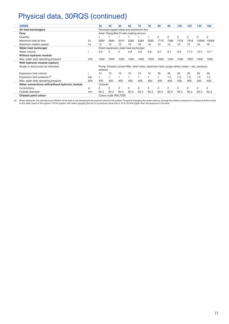
13
Physical data, 30RQS (continued)30RQS 39 45 50 60 70 78 80 90 100 120 140 160Air heat exchangers Grooved copper tubes and aluminium finsFans Axial Flying Bird IV with rotating shroudQuantity 1 1 1 1 1 1 2 2 2 2 2 2Maximum total air flow l/s 3692 3690 3910 5285 5284 5282 7770 7380 7376 7818 10568 10568Maximum rotation speed r/s 12 12 12 16 16 16 12 12 12 12 16 16Water heat exchanger Direct expansion. plate heat exchangerWater volume l 2.6 3 4 4.8 4.8 5.6 8.7 8.7 9.9 11.3 12.4 14.7Without hydronic module Max. water-side operating pressure kPa 1000 1000 1000 1000 1000 1000 1000 1000 1000 1000 1000 1000With hydronic module (option)Single or dual pump (as selected) Pump, Victaulic screen filter, relief valve, expansion tank, purge valves (water + air), pressure
sensorsExpansion tank volume l 12 12 12 12 12 12 35 35 35 35 35 35Expansion tank pressure (4) bar 1 1 1 1 1 1 1 1.5 1.5 1.5 1.5 1.5Max. water-side operating pressure kPa 400 400 400 400 400 400 400 400 400 400 400 400Water connections with/without hydronic module VictaulicConnections in 2 2 2 2 2 2 2 2 2 2 2 2Outside diameter mm 60.3 60.3 60.3 60.3 60.3 60.3 60.3 60.3 60.3 60.3 60.3 60.3Chassis paint colour Colour code: RAL7035
(4) When delivered, the standard pre-inflation of the tank is not necessarily the optimal value for the system. To permit changing the water volume, change the inflation pressure to a pressure that is close to the static head of the system. Fill the system with water (purging the air) to a pressure value that is 10 to 20 kPa higher than the pressure in the tank
14
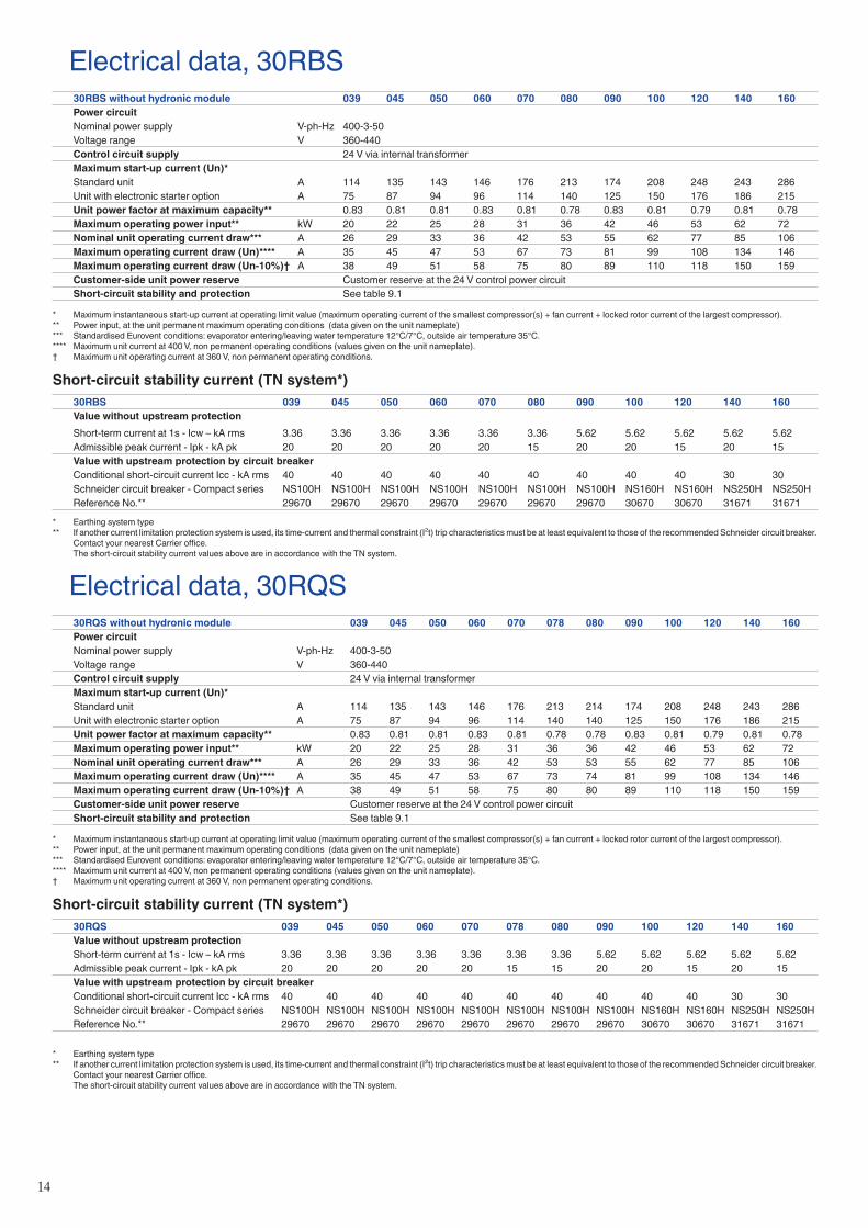
Electrical data, 30RBS30RBS without hydronic module 039 045 050 060 070 080 090 100 120 140 160Power circuitNominal power supply V-ph-Hz 400-3-50Voltage range V 360-440Control circuit supply 24 V via internal transformerMaximum start-up current (Un)*Standard unit A 114 135 143 146 176 213 174 208 248 243 286Unit with electronic starter option A 75 87 94 96 114 140 125 150 176 186 215Unit power factor at maximum capacity** 0.83 0.81 0.81 0.83 0.81 0.78 0.83 0.81 0.79 0.81 0.78Maximum operating power input** kW 20 22 25 28 31 36 42 46 53 62 72Nominal unit operating current draw*** A 26 29 33 36 42 53 55 62 77 85 106Maximum operating current draw (Un)**** A 35 45 47 53 67 73 81 99 108 134 146Maximum operating current draw (Un-10%)† A 38 49 51 58 75 80 89 110 118 150 159Customer-side unit power reserve Customer reserve at the 24 V control power circuitShort-circuit stability and protection See table 9.1
* Maximum instantaneous start-up current at operating limit value (maximum operating current of the smallest compressor(s) + fan current + locked rotor current of the largest compressor).** Power input, at the unit permanent maximum operating conditions (data given on the unit nameplate)*** Standardised Eurovent conditions: evaporator entering/leaving water temperature 12°C/7°C, outside air temperature 35°C.**** Maximum unit current at 400 V, non permanent operating conditions (values given on the unit nameplate).† Maximum unit operating current at 360 V, non permanent operating conditions.
Short-circuit stability current (TN system*)30RBS 039 045 050 060 070 080 090 100 120 140 160Value without upstream protectionShort-term current at 1s - Icw – kA rms 3.36 3.36 3.36 3.36 3.36 3.36 5.62 5.62 5.62 5.62 5.62Admissible peak current - Ipk - kA pk 20 20 20 20 20 15 20 20 15 20 15Value with upstream protection by circuit breakerConditional short-circuit current Icc - kA rms 40 40 40 40 40 40 40 40 40 30 30Schneider circuit breaker - Compact series NS100H NS100H NS100H NS100H NS100H NS100H NS100H NS160H NS160H NS250H NS250HReference No.** 29670 29670 29670 29670 29670 29670 29670 30670 30670 31671 31671
* Earthing system type** If another current limitation protection system is used, its time-current and thermal constraint (I²t) trip characteristics must be at least equivalent to those of the recommended Schneider circuit breaker.
Contact your nearest Carrier office. The short-circuit stability current values above are in accordance with the TN system.
Electrical data, 30RQS30RQS without hydronic module 039 045 050 060 070 078 080 090 100 120 140 160Power circuitNominal power supply V-ph-Hz 400-3-50Voltage range V 360-440Control circuit supply 24 V via internal transformerMaximum start-up current (Un)*Standard unit A 114 135 143 146 176 213 214 174 208 248 243 286Unit with electronic starter option A 75 87 94 96 114 140 140 125 150 176 186 215Unit power factor at maximum capacity** 0.83 0.81 0.81 0.83 0.81 0.78 0.78 0.83 0.81 0.79 0.81 0.78Maximum operating power input** kW 20 22 25 28 31 36 36 42 46 53 62 72Nominal unit operating current draw*** A 26 29 33 36 42 53 53 55 62 77 85 106Maximum operating current draw (Un)**** A 35 45 47 53 67 73 74 81 99 108 134 146Maximum operating current draw (Un-10%)† A 38 49 51 58 75 80 80 89 110 118 150 159Customer-side unit power reserve Customer reserve at the 24 V control power circuitShort-circuit stability and protection See table 9.1
* Maximum instantaneous start-up current at operating limit value (maximum operating current of the smallest compressor(s) + fan current + locked rotor current of the largest compressor).** Power input, at the unit permanent maximum operating conditions (data given on the unit nameplate)*** Standardised Eurovent conditions: evaporator entering/leaving water temperature 12°C/7°C, outside air temperature 35°C.**** Maximum unit current at 400 V, non permanent operating conditions (values given on the unit nameplate).† Maximum unit operating current at 360 V, non permanent operating conditions.
Short-circuit stability current (TN system*)30RQS 039 045 050 060 070 078 080 090 100 120 140 160Value without upstream protectionShort-term current at 1s - Icw – kA rms 3.36 3.36 3.36 3.36 3.36 3.36 3.36 5.62 5.62 5.62 5.62 5.62Admissible peak current - Ipk - kA pk 20 20 20 20 20 15 15 20 20 15 20 15Value with upstream protection by circuit breakerConditional short-circuit current Icc - kA rms 40 40 40 40 40 40 40 40 40 40 30 30Schneider circuit breaker - Compact series NS100H NS100H NS100H NS100H NS100H NS100H NS100H NS100H NS160H NS160H NS250H NS250HReference No.** 29670 29670 29670 29670 29670 29670 29670 29670 30670 30670 31671 31671
* Earthing system type** If another current limitation protection system is used, its time-current and thermal constraint (I²t) trip characteristics must be at least equivalent to those of the recommended Schneider circuit breaker.
Contact your nearest Carrier office. The short-circuit stability current values above are in accordance with the TN system.
15
Electrical data and operating conditions notes:• 30RB/RQ 039-160 units have a single power connection point located
immediately upstream of the field power connections.• The control box includes the following standard features: - starter and motor protection devices for each compressor, the fans and
the pump, - the control devices. - A main disconnect switch can be installed within the box with the
option 70.• Field connections: All connections to the system and the electrical installations must be in full
accordance with all applicable local codes.• The Carrier 30RB/RQ units are designed and built to ensure conformance
with these codes. The recommendations of European standard EN 60204-1 (machine safety - electrical machine components - part 1: general regulations - corresponds to IEC 60204-1) are specifically taken into account, when designing the electrical equipment*.
• An auxiliary contactor is available with the QF breaker allowing a safety channel installation to ensure a feedback output about heater and board power supply status and then prevent evaporator from frosting when heaters and boards are off.
NOTES: • Generally the recommendations of IEC 60364 are accepted as compliance
with the requirements of the installation directives. Conformance with EN 60204-1 is the best means of ensuring compliance with the Machines Directive § 1.5.1.
• Annex B of EN 60204-1 describes the electrical characteristics used for the operation of the machines.
• The operating environment for the 30RB/RQ units is specified below:1. Environment** - Environment as classified in EN 60721 (corresponds to
IEC 60721): - outdoor installation** - ambient temperature range: -20°C to +48°C, class 4K4H - altitude: ≤ 2000 m (for hydronic kit see chapter 9.2 of the installation
manual - presence of hard solids, class 4S2 (no significant dust present) - presence of corrosive and polluting substances, class 4C2 (negligible)2. Power supply frequency variation: ± 2 Hz.3. The neutral (N) conductor must not be connected directly to the unit (if
necessary use a transformer).4. Overcurrent protection of the power supply conductors is not provided with
the unit.5. The factory-installed disconnect switch (option 70) is of a type suitable for
power interruption in accordance with EN 60947.6. The units are designed for connection to TN(S) networks (IEC 60364). For
IT networks the earth connection must not be at the network earth. Provide a local earth, consult competent local organisations to complete the electrical installation. Units delivered with speed drive (options 28 and 116J/K/V/W) are not compatible with IT network.
Caution: If particular aspects of an actual installation do not conform to the conditions described above, or if there are other conditions which should be considered, always contact your local Carrier representative.
* The absence of main power disconnect switch on standard machines is an exception that must be taken in account at field installation level.
** The required protection level for this class is IP43BW (according to reference document IEC 60529). All 30RB/RQ units fulfil this protection condition.
- Closed electrical box is IP44CW - Open electrical box (when accessing to interface) is IPxxB
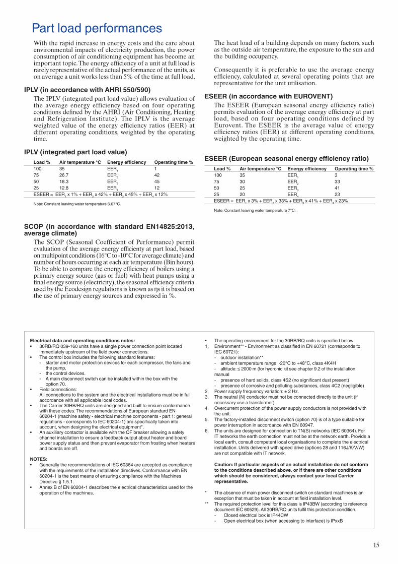
Part load performancesWith the rapid increase in energy costs and the care about environmental impacts of electricity production, the power consumption of air conditioning equipment has become an important topic. The energy efficiency of a unit at full load is rarely representative of the actual performance of the units, as on average a unit works less than 5% of the time at full load.
IPLV (in accordance with AHRI 550/590)The IPLV (integrated part load value) allows evaluation of the average energy efficiency based on four operating conditions defined by the AHRI (Air Conditioning, Heating and Refrigeration Institute). The IPLV is the average weighted value of the energy efficiency ratios (EER) at different operating conditions, weighted by the operating time.
IPLV (integrated part load value)Load % Air temperature °C Energy efficiency Operating time %100 35 EER1 175 26.7 EER2 4250 18.3 EER3 4525 12.8 EER4 12ESEER = EER1 x 1% + EER2 x 42% + EER3 x 45% + EER4 x 12%
Note: Constant leaving water temperature 6.67°C.
The heat load of a building depends on many factors, such as the outside air temperature, the exposure to the sun and the building occupancy.
Consequently it is preferable to use the average energy efficiency, calculated at several operating points that are representative for the unit utilisation.
ESEER (in accordance with EUROVENT)The ESEER (European seasonal energy efficiency ratio) permits evaluation of the average energy efficiency at part load, based on four operating conditions defined by Eurovent. The ESEER is the average value of energy efficiency ratios (EER) at different operating conditions, weighted by the operating time.
ESEER (European seasonal energy efficiency ratio)Load % Air temperature °C Energy efficiency Operating time %100 35 EER1 375 30 EER2 3350 25 EER3 4125 20 EER4 23ESEER = EER1 x 3% + EER2 x 33% + EER3 x 41% + EER4 x 23%
Note: Constant leaving water temperature 7°C.
SCOP (In accordance with standard EN14825:2013, average climate)
The SCOP (Seasonal Coefficient of Performance) permit evaluation of the average energy efficienty at part load, based on multipoint conditions (16°C to -10°C for average climate) and number of hours occurring at each air temperature (Bin hours).To be able to compare the energy efficiency of boilers using a primary energy source (gas or fuel) with heat pumps using a final energy source (electricity), the seasonal efficiency criteria used by the Ecodesign regulations is known as ŋs it is based on the use of primary energy sources and expressed in %.
16
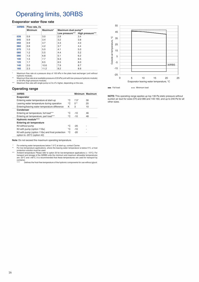
Operating limits, 30RBSEvaporator water flow rate
30RBS Flow rate, l/sMinimum Maximum* Maximum dual pump**
Low pressure*** High pressure***039 0.9 3.0 2.9 3.4045 0.9 3.4 3.2 3.8050 0.9 3.7 3.3 4.0060 0.9 4.2 3.7 4.4070 1.0 5.0 4.1 5.0080 1.2 5.5 4.4 5.2090 1.3 6.8 5.1 6.2100 1.5 7.7 6.3 6.5120 1.7 8.5 6.5 8.0140 2.0 10.6 7.9 8.7160 2.3 11.2 8.2 8.9
* Maximum flow rate at a pressure drop of 100 kPa in the plate heat exchanger (unit without hydronic module).
** Maximum flow rate at an available pressure of 20 kPa (unit with low-pressure hydronic module) or 50 kPa (high-pressure module).
*** Maximum flow rate with single pump is 2 to 4% higher, depending on the size.
Operating range30RBS Minimum MaximumEvaporatorEntering water temperature at start-up °C 7.5* 30Leaving water temperature during operation °C 5** 20Entering/leaving water temperature difference K 3 10CondenserEntering air temperature, full load*** °C -10 46Entering air temperature, part load*** °C -10 48Hydronic module****Entering air temperatureKit without pump °C -20 -Kit with pump (option 116x) °C -10 -Kit with pump (option 116x) and frost protection option to -20°C (option 42)
°C -20 -
Note: Do not exceed the maximum operating temperature.
* For entering water temperatures below 7.5°C at start-up, contact Carrier.** For low-temperature applications, where the leaving water temperature is below 5°C, a frost
protection solution must be used.*** Ambient temperature: Please refer to option 20 for low-temperature applications (< -10°C). For
transport and storage of the 30RBS units the minimum and maximum allowable temperatures are -20°C and +48°C. It is recommended that these temperatures are used for transport by container.
**** Defines the frost-free temperature of the hydronic components for use without glycol.
Out
side
air
tem
pera
ture
, °C
Evaporator leaving water temperature, °C
Full load Minimum load
NOTE: This operating range applies up top 130 Pa static pressure without suction air duct for sizes 070 and 080 and 140-160, and up to 240 Pa for all other sizes.
55
45
35
25
15
5
-5
-15
-250 5 10 15 20 25
30RBS
17
Operating limits, 30RQSWater heat exchanger water flow rate
30RQS Flow rate, l/sMinimum Maximum* Maximum dual pump**
Low pressure*** High pressure***039 0.9 3.0 2.9 3.4045 0.9 3.4 3.2 3.8050 0.9 4.2 3.7 4.4060 0.9 5.0 4.1 5.0070 1.0 5.0 4.1 5.0078 1.2 5.5 4.4 5.2080 1.2 6.8 5.1 6.2090 1.3 6.8 5.1 6.2100 1.5 7.7 6.3 6.5120 1.7 8.5 6.5 8.0140 2.0 10.6 7.9 8.7160 2.3 11.2 8.2 8.9
* Maximum flow rate at a pressure drop of 100 kPa in the plate heat exchanger (unit without hydronic module).
** Maximum flow rate at an available pressure of 20 kPa (unit with low-pressure hydronic module) or 50 kPa (high-pressure module).
*** Maximum flow rate with single pump is 2 to 4% higher, depending on the size.
Operating range, standard unit, cooling mode30RQS Minimum MaximumEvaporatorEntering water temperature at start-up °C 7,5 30Leaving water temperature during operation °C 5* 20Entering/leaving water temperature difference K 3 10CondenserEntering air temperature** °C -10 48Hydronic module***Entering air temperatureKit without pump °C -20 -Kit with pump (option 116x) °C 0 -Kit with pump (option 116x) and frost protection option to -20°C (option 42)
°C -20 -
Note: Do not exceed the maximum operating temperature.
* If the leaving water temperature is below 5°C, a frost protection solution must be used. ** For transport and storage of the 30RQS units the minimum and maximum allowable temperatures
are -20°C and +48°C. It is recommended that these temperatures are used for transport by container.
*** Defines the frost-free temperature of the hydronic components for use without glycol.
30RQS (cooling mode)
-20
-10
0
10
20
30
40
50
0 5 10 15 20 25
Full load Minimum load
Operating range, standard unit, heating mode30RQS Minimum MaximumCondenserEntering water temperature at start-up °C 8 45Leaving water temperature during operation °C 25 55Entering/leaving water temperature difference K 3 10EvaporatorAir temperature °C -15 40Hydronic module*Entering air temperatureKit without pump °C -20 -Kit with pump (option 116x) °C 0 -Kit with pump (option 116x) and frost protection option to -20°C (option 42)
°C -20 -
Note: Do not exceed the maximum operating temperature.
* Defines the frost-free temperature of the hydronic components for use without glycol.
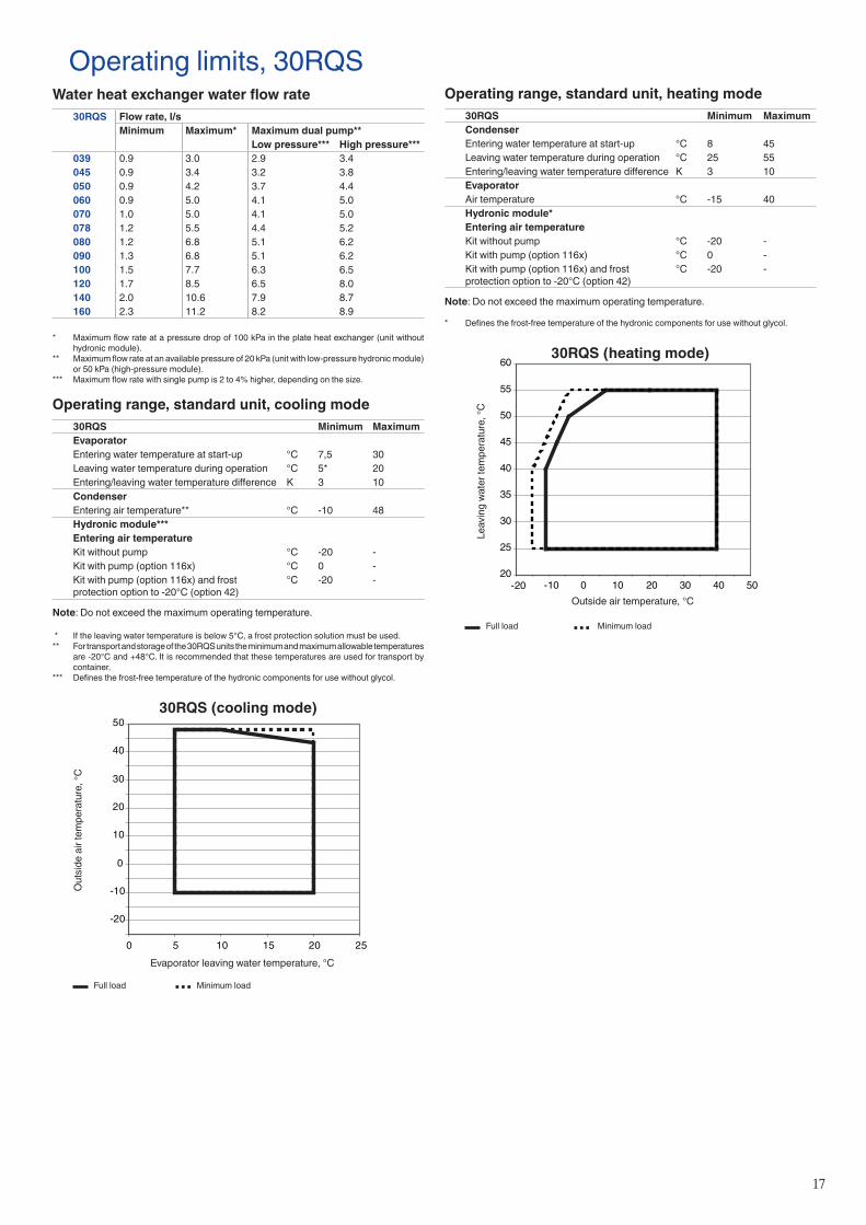
30RQS (heating mode)
20
25
30
35
40
45
50
55
60
-20 -10 0 10 20 30 40 50
Leav
ing
wate
r tem
pera
ture
, °C
Outside air temperature, °C
Full load Minimum load
Out
side
air
tem
pera
ture
, °C
Evaporator leaving water temperature, °C
18
0
1 2 3 4 5
2030
100
1
40 50 60 7080 90
110120130140150160170180190200
2 3 4 5 6 7 8 9
1 2 3 4 5 6
3,00,0 0,5 1,0 1,5 2,0 2,5 3,5 4,0 4,5 5,0 5,520
30
40
50
60
70
80
90
100
110
120
130
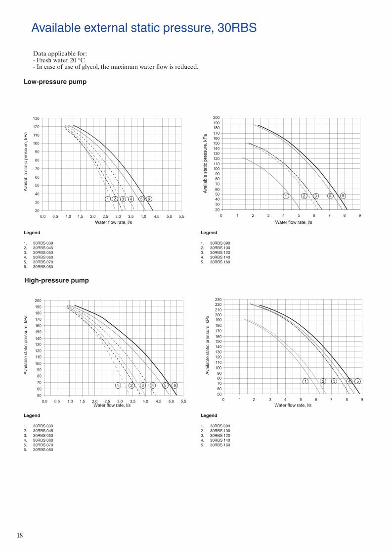
Available external static pressure, 30RBS
Avai
labl
e st
atic
pre
ssur
e, k
Pa
Water flow rate, l/s
Avai
labl
e st
atic
pre
ssur
e, k
Pa
Water flow rate, l/s
Legend
1. 30RBS 039 2. 30RBS 045 3. 30RBS 0504. 30RBS 0605. 30RBS 0706. 30RBS 080
Legend
1. 30RBS 090 2. 30RBS 1003. 30RBS 1204. 30RBS 1405. 30RBS 160
High-pressure pump
3,00,0 0,5 1,0 1,5 2,0 2,5 3,5 4,0 4,5 5,0 5,5
1 2 3 4 5 65
5060708090
100
110120130140
150160170180190200
4321
0 1 2 3 4 5 6 7 8 95060708090
100110120130140150160170180190200210220230
Legend
1. 30RBS 039 2. 30RBS 045 3. 30RBS 0504. 30RBS 0605. 30RBS 0706. 30RBS 080
Legend
1. 30RBS 090 2. 30RBS 1003. 30RBS 1204. 30RBS 1405. 30RBS 160
Avai
labl
e st
atic
pre
ssur
e, k
Pa
Water flow rate, l/s
Avai
labl
e st
atic
pre
ssur
e, k
Pa
Water flow rate, l/s
Data applicable for:- Fresh water 20 °C- In case of use of glycol, the maximum water flow is reduced.
Low-pressure pump
19
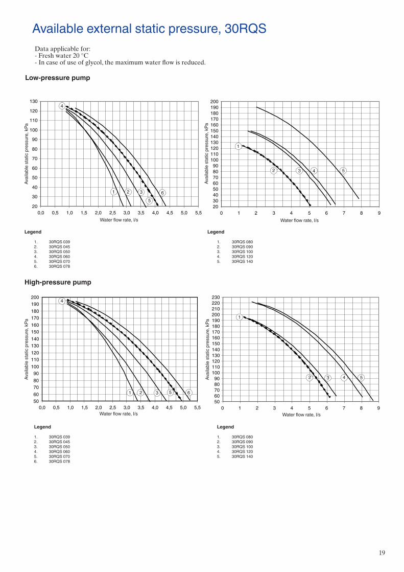
Available external static pressure, 30RQS
Water flow rate, l/sWater flow rate, l/s
Water flow rate, l/sWater flow rate, l/s
High-pressure pump
20
30
40
50
60
70
80
90
100
110
120
130
0,0 0,5 1,0 1,5 2,0 2,5 3,0 3,5 4,0 4,5 5,0 5,5
65
321
4
2030405060708090
100110120130140150160170180190200
0 1 2 3 4 5 6 7 8 9
1
2 3 4 5
5060708090
100110120130140150160170180190200
0,0 0,5 1,0 1,5 2,0 2,5 3,0 3,5 4,0 4,5 5,0 5,5
4
1 2 3 5 6
5060708090
100110120130140150160170180190200210220230
0 1 2 3 4 5 6 7 8 9
1
2 3 4 5
Legend
1. 30RQS 039 2. 30RQS 045 3. 30RQS 050 4. 30RQS 060 5. 30RQS 070 6. 30RQS 078
Legend
1. 30RQS 080 2. 30RQS 090 3. 30RQS 100 4. 30RQS 120 5. 30RQS 140
Legend
1. 30RQS 039 2. 30RQS 045 3. 30RQS 050 4. 30RQS 060 5. 30RQS 070 6. 30RQS 078
Legend
1. 30RQS 080 2. 30RQS 090 3. 30RQS 100 4. 30RQS 120 5. 30RQS 140
Avai
labl
e st
atic
pre
ssur
e, k
Pa
Avai
labl
e st
atic
pre
ssur
e, k
Pa
Avai
labl
e st
atic
pre
ssur
e, k
Pa
Avai
labl
e st
atic
pre
ssur
e, k
Pa
Data applicable for:- Fresh water 20 °C- In case of use of glycol, the maximum water flow is reduced.
Low-pressure pump
20
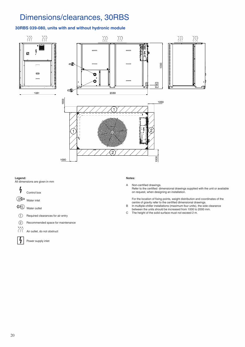
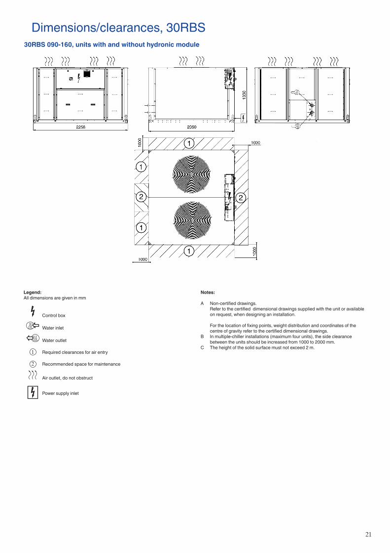
Legend:All dimensions are given in mm
Control box
Water inlet
Water outlet
1 Required clearances for air entry 2 Recommended space for maintenance
Air outlet, do not obstruct
Power supply inlet
Notes:
A Non-certified drawings. Refer to the certified dimensional drawings supplied with the unit or available
on request, when designing an installation.
For the location of fixing points, weight distribution and coordinates of the centre of gravity refer to the certified dimensional drawings.
B In multiple-chiller installations (maximum four units), the side clearance between the units should be increased from 1000 to 2000 mm.
C The height of the solid surface must not exceed 2 m.
Dimensions/clearances, 30RBS30RBS 039-080, units with and without hydronic module
21
Notes:
A Non-certified drawings. Refer to the certified dimensional drawings supplied with the unit or available
on request, when designing an installation.
For the location of fixing points, weight distribution and coordinates of the centre of gravity refer to the certified dimensional drawings.
B In multiple-chiller installations (maximum four units), the side clearance between the units should be increased from 1000 to 2000 mm.
C The height of the solid surface must not exceed 2 m.
Dimensions/clearances, 30RBS30RBS 090-160, units with and without hydronic module
Legend:All dimensions are given in mm
Control box
Water inlet
Water outlet
1 Required clearances for air entry 2 Recommended space for maintenance
Air outlet, do not obstruct
Power supply inlet
22
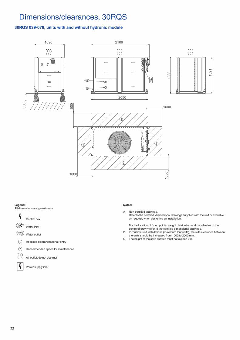
Dimensions/clearances, 30RQS30RQS 039-078, units with and without hydronic module
Notes:
A Non-certified drawings. Refer to the certified dimensional drawings supplied with the unit or available
on request, when designing an installation.
For the location of fixing points, weight distribution and coordinates of the centre of gravity refer to the certified dimensional drawings.
B In multiple-unit installations (maximum four units), the side clearance between the units should be increased from 1000 to 2000 mm.
C The height of the solid surface must not exceed 2 m.
Legend:All dimensions are given in mm
Control box
Water inlet
Water outlet
1 Required clearances for air entry
2 Recommended space for maintenance
Air outlet, do not obstruct
Power supply inlet
1
1
1000
10001000
1000
2050
1330
300
2
2
23
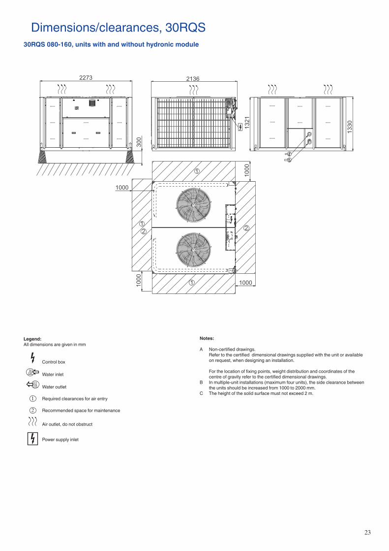
Dimensions/clearances, 30RQS30RQS 080-160, units with and without hydronic module
Notes:
A Non-certified drawings. Refer to the certified dimensional drawings supplied with the unit or available
on request, when designing an installation.
For the location of fixing points, weight distribution and coordinates of the centre of gravity refer to the certified dimensional drawings.
B In multiple-unit installations (maximum four units), the side clearance between the units should be increased from 1000 to 2000 mm.
C The height of the solid surface must not exceed 2 m.
Legend:All dimensions are given in mm
Control box
Water inlet
Water outlet
1 Required clearances for air entry
2 Recommended space for maintenance
Air outlet, do not obstruct
Power supply inlet
-A-
1
1
1
2136
1321
1000
10001000
1000
300
22
24
Dimensions/clearances for 30RBS/RQS units with option 49Position of the desuperheater inlets and outlets
30RBS/RQS 039-080
30RBS/RQS 090-120
30RBS/RQS 140-160
Unit water inlet and outlet
Water inlet and outlet, unit with option 49

25

26
Order No.: 13461, 12.2016. Supersedes order No.: 13461, 04.2016. Manufactured by: Carrier SCS, Montluel, France.Manufacturer reserves the right to change any product specifications without notice. Printed in the European Union.


![Mekaniikka Dynamiikka Kinematiikka - teho- · PDF file2 Keskimääräinen teho P k ' n W t [P k] = J/s = W, watti. Hetkellinen teho P ' Fv Hyötysuhde η ' P anto P otto ' E anto E](https://static.fdocument.org/doc/165x107/5a9e4c197f8b9a75458d2c02/mekaniikka-dynamiikka-kinematiikka-teho-keskimrinen-teho-p-k-n-w-t-p-k-.jpg)
![1 to 14 pF 1 to 20 pF air - Farnell · PDF fileBed] HejWj_edWb b_\[ ?dikbWj_ed h[i_ijWdY[0 4 '&, C ... bem ZodWc_Y jkd_d] de_i[$ air capacitors capacitance range series Q @ 250 MHz](https://static.fdocument.org/doc/165x107/5ab5121e7f8b9adc638ca6ff/1-to-14-pf-1-to-20-pf-air-farnell-hejwjedwb-b-dikbwjed-hiijwdy0-4-.jpg)