2-D Color Vision Measuring System QUICK IMAGE Series
16
Bulletin No. 2186 2-D Color Vision Measuring System QUICK IMAGE Series Vision Measuring System
Transcript of 2-D Color Vision Measuring System QUICK IMAGE Series
Bulletin No. 2186
2-D Color Vision Measuring SystemQUICK IMAGE Series
Visio
n M
easu
ring
Syst
em
2
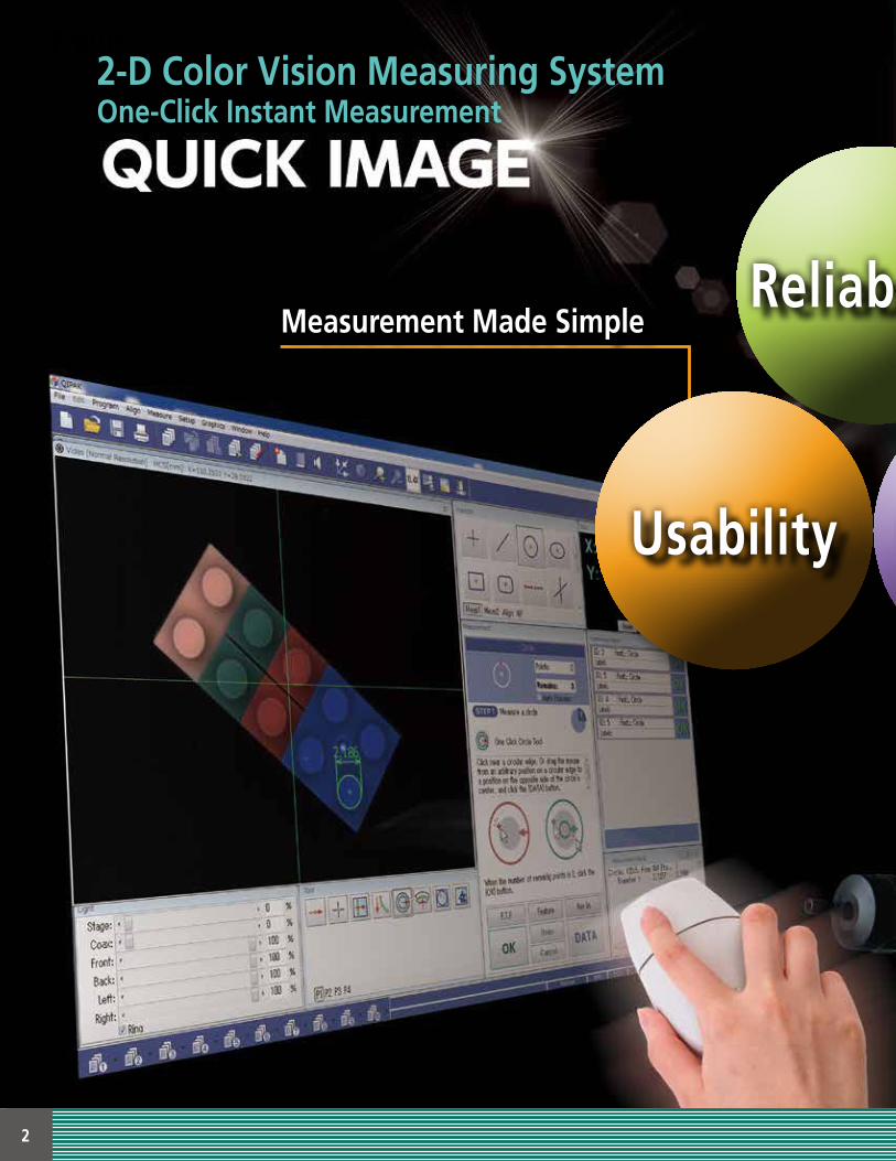
2-D Color Vision Measuring SystemOne-Click Instant Measurement
Reliab ility
Usability Efficiency
Measurement Made Simple
3
Reliab ility
Efficiency
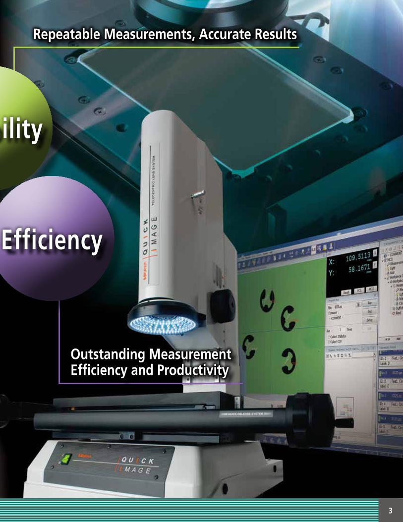
Repeatable Measurements, Accurate Results
Outstanding MeasurementEfficiency and Productivity
4
Repeatable Measurements, Accurate ResultsReliability
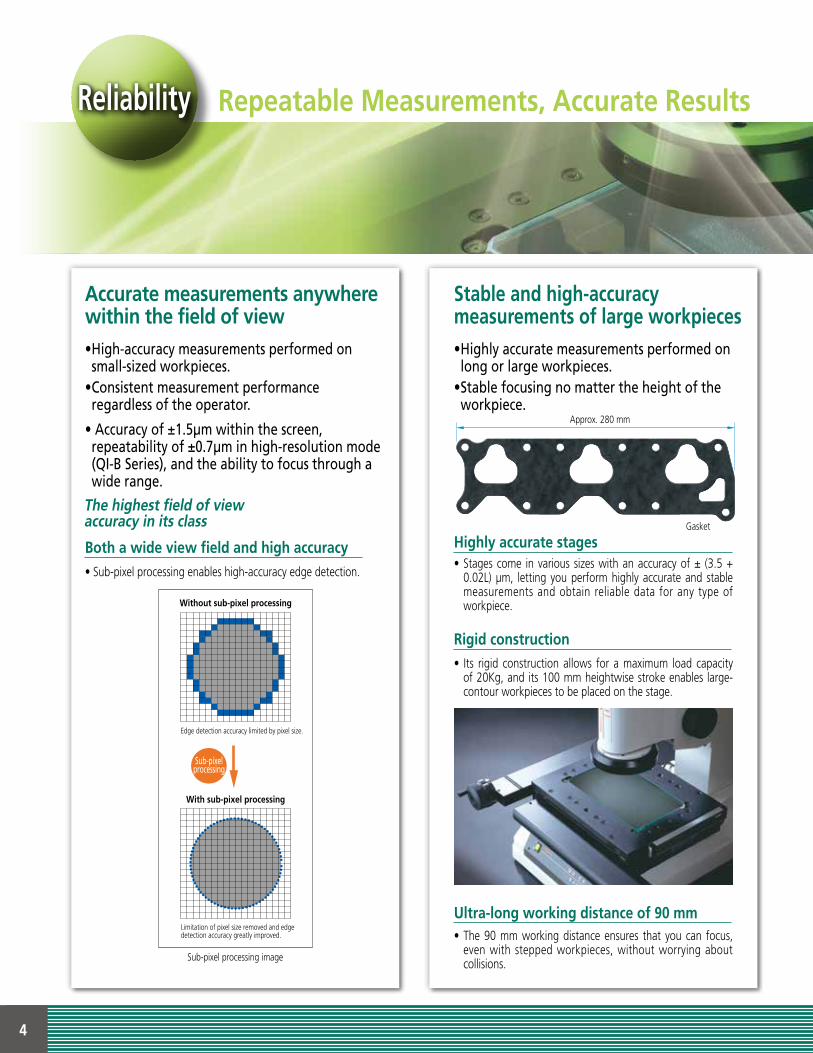
Accurate measurements anywhere within the field of view
The highest field of viewaccuracy in its class
•High-accuracymeasurementsperformedon small-sizedworkpieces.
•Consistentmeasurementperformanceregardlessoftheoperator.
•Accuracyof±1.5μmwithinthescreen,repeatabilityof±0.7μminhigh-resolutionmode(QI-BSeries),andtheabilitytofocusthroughawiderange.
Stable and high-accuracymeasurements of large workpieces
Highly accurate stages
Rigid construction
Ultra-long working distance of 90 mm
Both a wide view field and high accuracy
•Highlyaccuratemeasurementsperformedonlongorlargeworkpieces.
•Stablefocusingnomattertheheightoftheworkpiece.
• Stages come in various sizes with an accuracy of ± (3.5 + 0.02L) μm, letting you perform highly accurate and stable measurements and obtain reliable data for any type of workpiece.
• Its rigid construction allows for a maximum load capacity of 20Kg, and its 100 mm heightwise stroke enables large-contour workpieces to be placed on the stage.
• The 90 mm working distance ensures that you can focus, even with stepped workpieces, without worrying about collisions.
• Sub-pixel processing enables high-accuracy edge detection.
Gasket
Approx. 280 mm
Without sub-pixel processing
Edge detection accuracy limited by pixel size.
Limitation of pixel size removed and edge detection accuracy greatly improved.
With sub-pixel processing
Sub-pixelprocessing
Sub-pixel processing image
5
Repeatable Measurements, Accurate Results
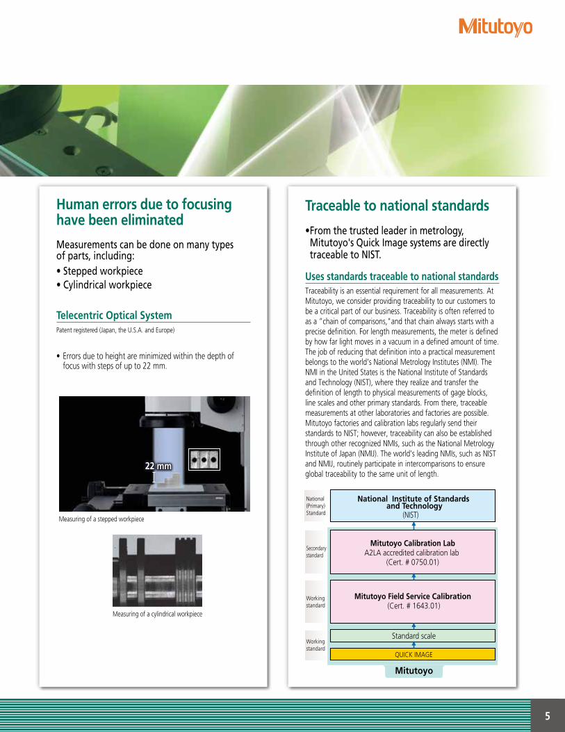
Human errors due to focusinghave been eliminated
Telecentric Optical System
Measurementscanbedoneonmanytypesofparts,including:•Steppedworkpiece•Cylindricalworkpiece
• Errors due to height are minimized within the depth of focus with steps of up to 22 mm.
Traceable to national standards
Uses standards traceable to national standards
•Fromthetrustedleaderinmetrology,Mitutoyo'sQuickImagesystemsaredirectlytraceabletoNIST.
Traceability is an essential requirement for all measurements. At Mitutoyo, we consider providing traceability to our customers to be a critical part of our business. Traceability is often referred to as a ”chain of comparisons,"and that chain always starts with a precise definition. For length measurements, the meter is defined by how far light moves in a vacuum in a defined amount of time. The job of reducing that definition into a practical measurement belongs to the world’s National Metrology Institutes (NMI). The NMI in the United States is the National Institute of Standards and Technology (NIST), where they realize and transfer the definition of length to physical measurements of gage blocks, line scales and other primary standards. From there, traceable measurements at other laboratories and factories are possible. Mitutoyo factories and calibration labs regularly send their standards to NIST; however, traceability can also be established through other recognized NMIs, such as the National Metrology Institute of Japan (NMIJ). The world’s leading NMIs, such as NIST and NMIJ, routinely participate in intercomparisons to ensure global traceability to the same unit of length.
National(Primary)Standard (NIST)
National Institute of Standards and Technology
Secondary standard
Working standard
Working standard
Standard scale
QUICK IMAGE
Mitutoyo Field Service Calibration (Cert. # 1643.01)
Mitutoyo
Mitutoyo Calibration LabA2LA accredited calibration lab
(Cert. # 0750.01)
22 mm
Patent registered (Japan, the U.S.A. and Europe)
Measuring of a cylindrical workpiece
Measuring of a stepped workpiece
6
Measurement Made SimpleUsability
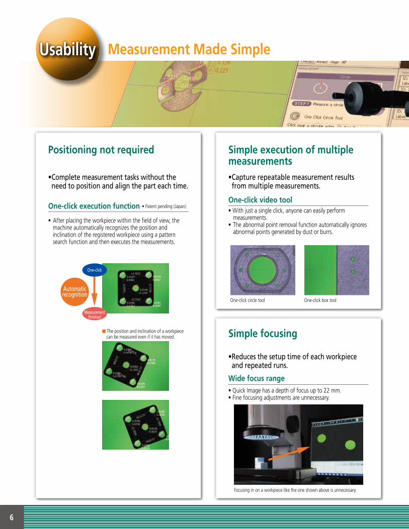
Positioning not required Simple execution of multiple measurements
Simple focusing
One-click execution function
One-click video tool
Wide focus range
•Completemeasurementtaskswithouttheneedtopositionandaligntheparteachtime.
•Capturerepeatablemeasurementresultsfrommultiplemeasurements.
•Reducesthesetuptimeofeachworkpieceandrepeatedruns.
• After placing the workpiece within the field of view, the machine automatically recognizes the position and
inclination of the registered workpiece using a pattern search function and then executes the measurements.
• With just a single click, anyone can easily perform measurements.• The abnormal point removal function automatically ignores abnormal points generated by dust or burrs.
• Quick Image has a depth of focus up to 22 mm.• Fine focusing adjustments are unnecessary.
One-click circle tool One-click box tool
Measurement finished
One-click
Automaticrecognition
The position and inclination of a workpiece can be measured even if it has moved.
Focusing in on a workpiece like the one shown above is unnecessary.
• Patent pending (Japan)
7
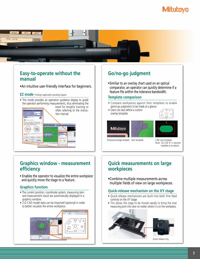
Go/no-go judgmentEasy-to-operate without the manual
Graphics window - measurement efficiency
Template comparison
EZ mode
Graphics function
•Similiartoanoverlaychartusedonanopticalcomparator,anoperatorcanquicklydetermineifafeaturefitswithinthetolerancebandwidth.
•Anintuitiveuser-friendlyinterfaceforbeginners.
• The current position, coordinate system, measuring item and measurement result are automatically displayed in a graphics window.• 2-D CAD model data can be imported (optional) in order to better visualize the entire workpiece.
•Enablestheoperatortovisualizetheentireworkpieceandquicklymovethestagetoafeature.
• This mode provides an operation guidance display to guide the operator performing measurements, thus eliminating the
need for lengthy training or often referring to the instruc-tion manual.
CAD user templateNote: QS-CAD I/F is required
(available as an option).
User templateEnhanced rectangle template
Quick measurements on large workpieces
•Combinemultiplemeasurementsacross multiplefieldsofviewonlargeworkpieces.
Quick-release mechanism on the XY stage• Quick-release mechanisms are built into both fine feed
controls on the XY stage.• This allows the stage to be moved rapidly to bring the next
measuring point into view no matter where it is on the workpiece.
Quick-release ring
• Design application pending (Japan)
• Compare workpieces against their templates to enable go/no-go judgments to be made at a glance.
• Users can also define a custom overlay template.
8
Measure multiple workpieces simultaneously
•Batchmeasureseveralworkpiecesinasinglesetup.
•Usepatternsearchformultipleworkpieceswithinthe screen view, andmeasure themall inoneoperationwiththeone-clickexecutionfunction.
•Measurementscanbeperformedveryefficientlymakingaccuratepositioningunnecessary, andeliminatingtheneedforcostlyholdingfixtures.
Outstanding Measurement Efficiency and Product ivityEfficiency
Confirm measurement results quickly and easily•Intuitivelydeterminethemeasurement resultsandmeasurementpositionataglance. Video window measurement results• Measurement results can be understood intuitively just by
looking at a measurement image.• Change the display color of the go/no-go result to immediately
perform tolerance determination as well as determine no-go items.• Paste measurement images in inspection results report.
The measurement results display for go/no-go can be color-coded to meet your requirements.
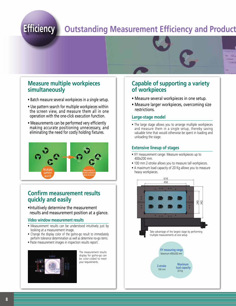
Capable of supporting a variety of workpieces
Large-stage model
•Measureseveralworkpiecesinonesetup.•Measurelargerworkpieces,overcomingsizerestrictions.
• The large stage allows you to arrange multiple workpieces and measure them in a single setup, thereby saving valuable time that would otherwise be spent in loading and unloading the stage.
Extensive lineup of stages• XY measurement range: Measure workpieces up to
400x200 mm.• 100 mm Z-stroke allows you to measure tall workpieces.• A maximum load capacity of 20 Kg allows you to measure
heavy workpieces.
XY measuring rangeMaximum 400x200 mm
Maximum load capacity
20 Kg
Z-stroke100 mm
342
240
450610
Take advantage of the largest stage by performing multiple measurements at one setup.
Multiplepatternsearch
Measurementofseveralworkpiecesdoneallatonce
9
Outstanding Measurement Efficiency and Product ivity
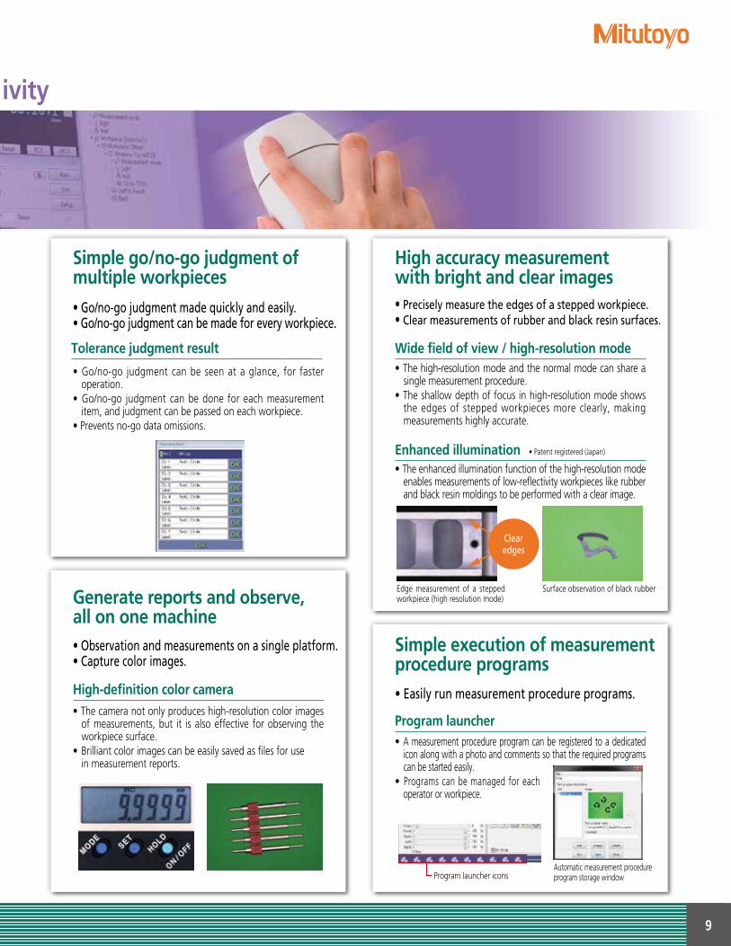
Generate reports and observe, all on one machine•Observationandmeasurementsonasingleplatform.•Capturecolorimages. High-definition color camera• The camera not only produces high-resolution color images
of measurements, but it is also effective for observing the workpiece surface.
• Brilliant color images can be easily saved as files for use in measurement reports.
Simple execution of measurement procedure programs•Easilyrunmeasurementprocedureprograms. Program launcher• A measurement procedure program can be registered to a dedicated
icon along with a photo and comments so that the required programs can be started easily.
• Programs can be managed for each operator or workpiece.
Automatic measurement procedure program storage window
High accuracy measurement with bright and clear images•Preciselymeasuretheedgesofasteppedworkpiece.•Clearmeasurementsofrubberandblackresinsurfaces. Wide field of view / high-resolution mode• The high-resolution mode and the normal mode can share a
single measurement procedure.• The shallow depth of focus in high-resolution mode shows
the edges of stepped workpieces more clearly, making measurements highly accurate.
Surface observation of black rubberEdge measurement of a stepped workpiece (high resolution mode)
Simple go/no-go judgment of multiple workpieces•Go/no-gojudgmentmadequicklyandeasily.•Go/no-gojudgmentcanbemadeforeveryworkpiece. Tolerance judgment result
Enhanced illumination
• Go/no-go judgment can be seen at a glance, for faster operation.
• Go/no-go judgment can be done for each measurement item, and judgment can be passed on each workpiece.
• Prevents no-go data omissions.
• The enhanced illumination function of the high-resolution mode enables measurements of low-reflectivity workpieces like rubber and black resin moldings to be performed with a clear image.
Clearedges
• Patent registered (Japan)
Program launcher icons
10
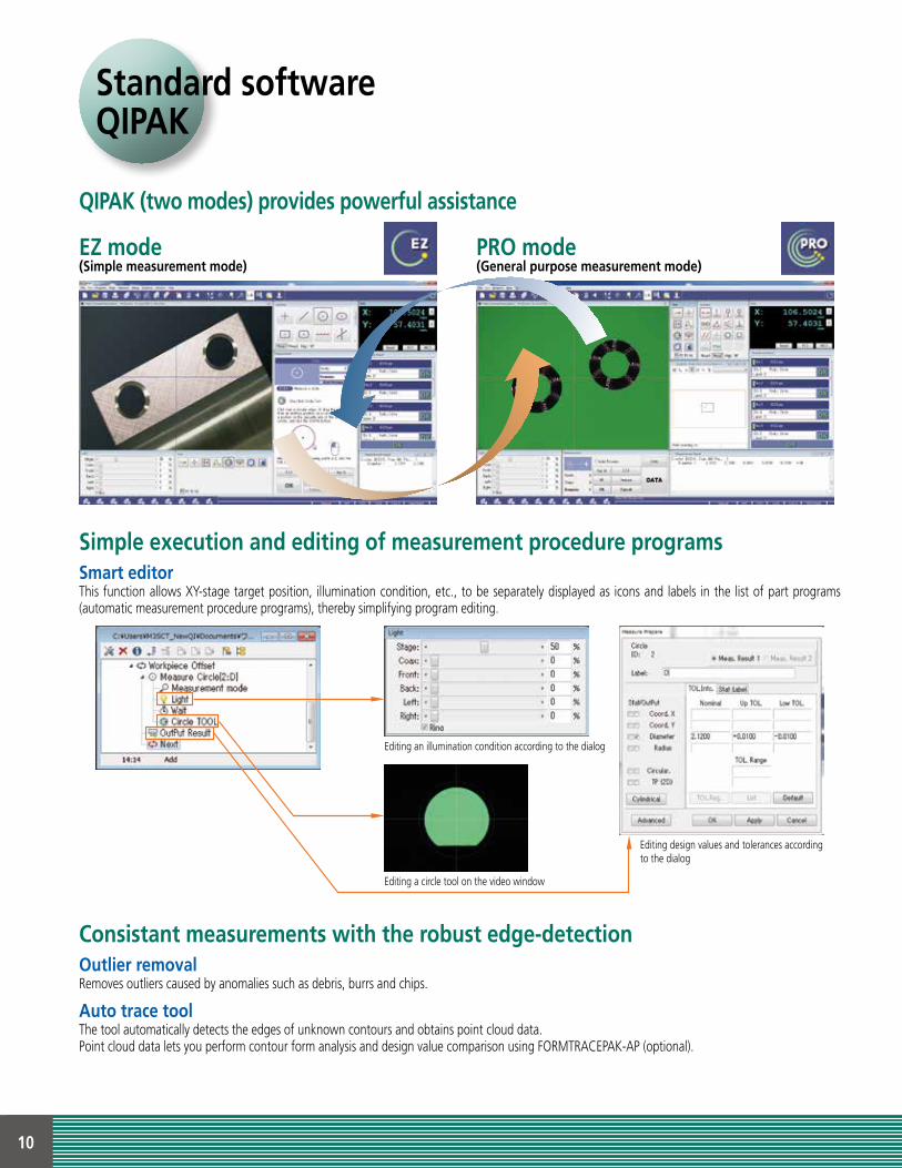
Standard softwareQIPAK
QIPAK (two modes) provides powerful assistance
Consistant measurements with the robust edge-detectionOutlier removal
Auto trace tool
Removes outliers caused by anomalies such as debris, burrs and chips.
The tool automatically detects the edges of unknown contours and obtains point cloud data.Point cloud data lets you perform contour form analysis and design value comparison using FORMTRACEPAK-AP (optional).
EZ mode(Simple measurement mode)
PRO mode(General purpose measurement mode)
Simple execution and editing of measurement procedure programsSmart editorThis function allows XY-stage target position, illumination condition, etc., to be separately displayed as icons and labels in the list of part programs (automatic measurement procedure programs), thereby simplifying program editing.
Editing an illumination condition according to the dialog
Editing a circle tool on the video window
Editing design values and tolerances according to the dialog
11
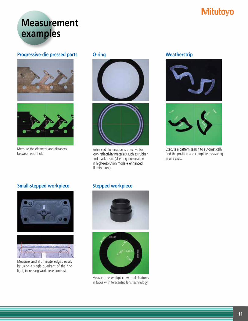
Measurementexamples
Progressive-die pressed parts
Small-stepped workpiece
O-ring
Stepped workpiece
Weatherstrip
Measure the diameter and distancesbetween each hole.
Measure and illuminate edges easily by using a single quadrant of the ring light, increasing workpiece contrast.
Enhanced illumination is effective for low- reflectivity materials such as rubber and black resin. (Use ring illumination in high-resolution mode + enhanced illumination.)
Measure the workpiece with all features in focus with telecentric lens technology.
Execute a pattern search to automatically find the position and complete measuring in one click.
12
Early detection of process irregularities
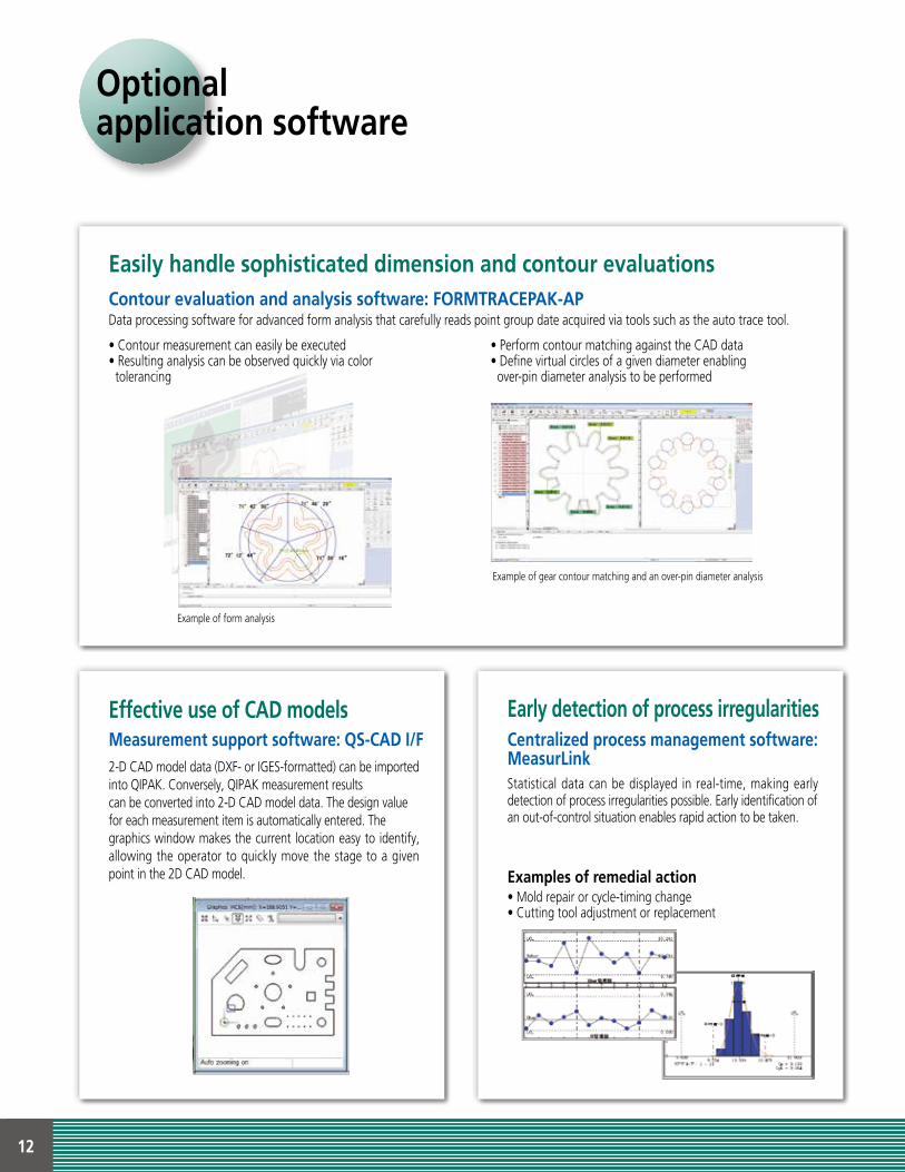
Optionalapplication software
Examples of remedial action
Centralized process management software: MeasurLinkStatistical data can be displayed in real-time, making early detection of process irregularities possible. Early identification ofan out-of-control situation enables rapid action to be taken.
• Mold repair or cycle-timing change• Cutting tool adjustment or replacement
Effective use of CAD modelsMeasurement support software: QS-CAD I/F2-D CAD model data (DXF- or IGES-formatted) can be imported into QIPAK. Conversely, QIPAK measurement resultscan be converted into 2-D CAD model data. The design valuefor each measurement item is automatically entered. Thegraphics window makes the current location easy to identify, allowing the operator to quickly move the stage to a given point in the 2D CAD model.
Easily handle sophisticated dimension and contour evaluations
• Contour measurement can easily be executed• Resulting analysis can be observed quickly via color tolerancing
• Perform contour matching against the CAD data• Define virtual circles of a given diameter enabling over-pin diameter analysis to be performed
Contour evaluation and analysis software: FORMTRACEPAK-APData processing software for advanced form analysis that carefully reads point group date acquired via tools such as the auto trace tool.
Example of form analysis
Example of gear contour matching and an over-pin diameter analysis
13
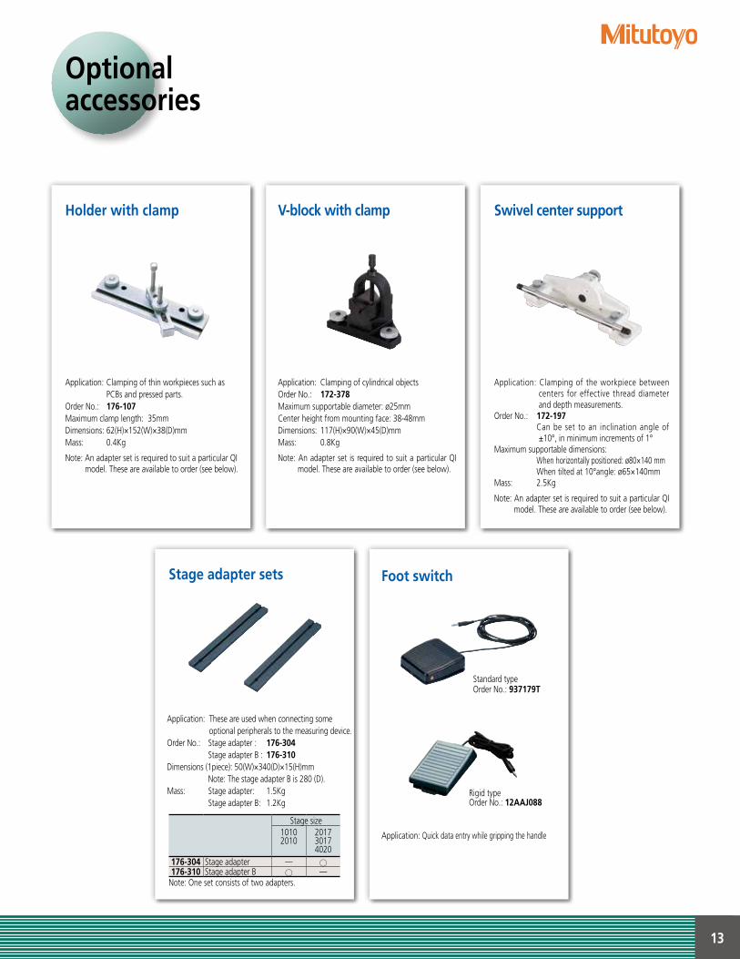
Optionalaccessories
Foot switch
Standard typeOrder No.: 937179T
Rigid typeOrder No.: 12AAJ088
Stage adapter sets
V-block with clamp Swivel center supportHolder with clamp
Application: These are used when connecting some optional peripherals to the measuring device.
Order No.: Stage adapter : 176-304 Stage adapter B : 176-310Dimensions (1piece): 50(W)×340(D)×15(H)mm Note: The stage adapter B is 280 (D).Mass: Stage adapter: 1.5Kg Stage adapter B: 1.2Kg
Application: Quick data entry while gripping the handle
Application: Clamping of cylindrical objectsOrder No.: 172-378Maximum supportable diameter: ø25mmCenter height from mounting face: 38-48mmDimensions: 117(H)×90(W)×45(D)mmMass: 0.8Kg
Note: An adapter set is required to suit a particular QI model. These are available to order (see below).
Application: Clamping of the workpiece between centers for effective thread diameter and depth measurements.
Order No.: 172-197 Can be set to an inclination angle of
±10°, in minimum increments of 1°Maximum supportable dimensions: When horizontally positioned: ø80×140 mm When tilted at 10°angle: ø65×140mmMass: 2.5Kg
Note: An adapter set is required to suit a particular QI model. These are available to order (see below).
Application: Clamping of thin workpieces such as PCBs and pressed parts.
Order No.: 176-107Maximum clamp length: 35mmDimensions: 62(H)×152(W)×38(D)mmMass: 0.4Kg
Note: An adapter set is required to suit a particular QI model. These are available to order (see below).
Stage size10102010
201730174020
176-304 Stage adapter —176-310 Stage adapter B —
Note: One set consists of two adapters.
14
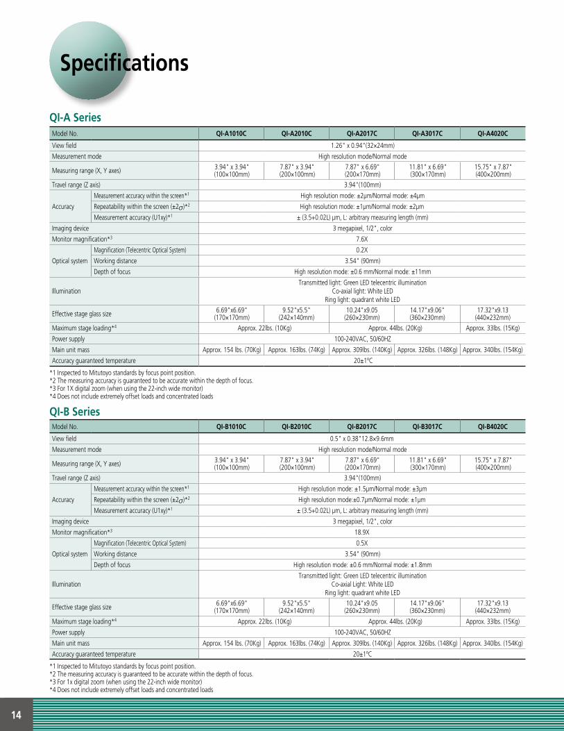
Model No. QI-A1010C QI-A2010C QI-A2017C QI-A3017C QI-A4020C
View field 1.26" x 0.94"(32×24mm)
Measurement mode High resolution mode/Normal mode
Measuring range (X, Y axes) 3.94" x 3.94"(100×100mm)
7.87" x 3.94"(200×100mm)
7.87" x 6.69"(200×170mm)
11.81" x 6.69"(300×170mm)
15.75" x 7.87"(400×200mm)
Travel range (Z axis) 3.94"(100mm)
Accuracy
Measurement accuracy within the screen*1 High resolution mode: ±2µm/Normal mode: ±4µm
Repeatability within the screen (±2 )*2 High resolution mode: ±1µm/Normal mode: ±2µm
Measurement accuracy (U1xy)*1 ± (3.5+0.02L) µm, L: arbitrary measuring length (mm)
Imaging device 3 megapixel, 1/2", color
Monitor magnification*3 7.6X
Optical system
Magnification (Telecentric Optical System) 0.2X
Working distance 3.54" (90mm)
Depth of focus High resolution mode: ±0.6 mm/Normal mode: ±11mm
IlluminationTransmitted light: Green LED telecentric illumination
Co-axial light: White LEDRing light: quadrant white LED
Effective stage glass size 6.69"x6.69"(170×170mm)
9.52"x5.5"(242×140mm)
10.24"x9.05(260×230mm)
14.17"x9.06"(360×230mm)
17.32"x9.13 (440×232mm)
Maximum stage loading*4 Approx. 22lbs. (10Kg) Approx. 44lbs. (20Kg) Approx. 33lbs. (15Kg)
Power supply 100-240VAC, 50/60HZ
Main unit mass Approx. 154 lbs. (70Kg) Approx. 163lbs. (74Kg) Approx. 309lbs. (140Kg) Approx. 326lbs. (148Kg) Approx. 340lbs. (154Kg)
Accuracy guaranteed temperature 20±1ºC
*1 Inspected to Mitutoyo standards by focus point position.*2 The measuring accuracy is guaranteed to be accurate within the depth of focus.*3 For 1X digital zoom (when using the 22-inch wide monitor)*4 Does not include extremely offset loads and concentrated loads
Model No. QI-B1010C QI-B2010C QI-B2017C QI-B3017C QI-B4020C
View field 0.5" x 0.38"12.8×9.6mm
Measurement mode High resolution mode/Normal mode
Measuring range (X, Y axes) 3.94" x 3.94"(100×100mm)
7.87" x 3.94"(200×100mm)
7.87" x 6.69"(200×170mm)
11.81" x 6.69"(300×170mm)
15.75" x 7.87"(400×200mm)
Travel range (Z axis) 3.94"(100mm)
Accuracy
Measurement accuracy within the screen*1 High resolution mode: ±1.5µm/Normal mode: ±3µm
Repeatability within the screen (±2 )*2 High resolution mode:±0.7µm/Normal mode: ±1µm
Measurement accuracy (U1xy)*1 ± (3.5+0.02L) µm, L: arbitrary measuring length (mm)
Imaging device 3 megapixel, 1/2", color
Monitor magnification*3 18.9X
Optical system
Magnification (Telecentric Optical System) 0.5X
Working distance 3.54" (90mm)
Depth of focus High resolution mode: ±0.6 mm/Normal mode: ±1.8mm
IlluminationTransmitted light: Green LED telecentric illumination
Co-axial Light: White LEDRing light: quadrant white LED
Effective stage glass size 6.69"x6.69"(170×170mm)
9.52"x5.5"(242×140mm)
10.24"x9.05(260×230mm)
14.17"x9.06"(360×230mm)
17.32"x9.13 (440×232mm)
Maximum stage loading*4 Approx. 22lbs. (10Kg) Approx. 44lbs. (20Kg) Approx. 33lbs. (15Kg)
Power supply 100-240VAC, 50/60HZ
Main unit mass Approx. 154 lbs. (70Kg) Approx. 163lbs. (74Kg) Approx. 309lbs. (140Kg) Approx. 326lbs. (148Kg) Approx. 340lbs. (154Kg)
Accuracy guaranteed temperature 20±1ºC
*1 Inspected to Mitutoyo standards by focus point position.*2 The measuring accuracy is guaranteed to be accurate within the depth of focus.*3 For 1x digital zoom (when using the 22-inch wide monitor)*4 Does not include extremely offset loads and concentrated loads
QI-A Series
QI-B Series
Specifications
15
9.72
”(24
7)
9.72
”(24
7)8.0
5”(20
4.5)
7.81”
(198.5
)4.74”(120.5)14.17”(360)2.11”
(53.5)
2.78”(70.5) 21.69”(551) 3.64”
(92.5)28.11”(714)
3.39
”(8
6)26
.69”
(678
)0.
67”(
17)
30.7
5”(7
81)
21.02”(534)
26.85”(682)8.86”(220.5)
29.78”(756.5)10.69”(271.5)
4.92”(125)
34.44”(875)
6.36”(161.5)
0.67”
(17)
26.6
9”(6
78)
3.62
”(9
2)30
.98”
(787
)
2.78”(70.5) 28.11”(714)
21.69”(551) 3.64”(92.5)
3.48”(88.5) 14.17”(360)
6.91”(175.5)
24.57”(624)
5.77”(146.5)
5.77”(146.5)24.45”(621) 3.64”
(92.5)3.64”(92.5)33.86”(860)
24.45”(621)33.86”(860)
0.67
”(17
)
0.67
”(17
)
31.2
2”(7
93)
0.77
”(1
9.5)
0.77
”(1
9.5)
0.77
”(1
9.5)
32.6
6”(8
29.5
)
31.2
2”(7
93)
32.6
6”(8
29.5
)
4.00”(101.5)
4.00”(101.5)14.17”(360)
14.17”(360)
14.17”(360)6.71”(170.5)
24.88”(632)
9.72
”(24
7)
24.45”(621) 3.64”(92.5)
0.67
”(17
)31
.22”
(793
)32
.66”
(829
.5)
3.54”
(90)
3.54”
(90)
3.54”
(90)
3.54”
(90)
3.54”
(90)
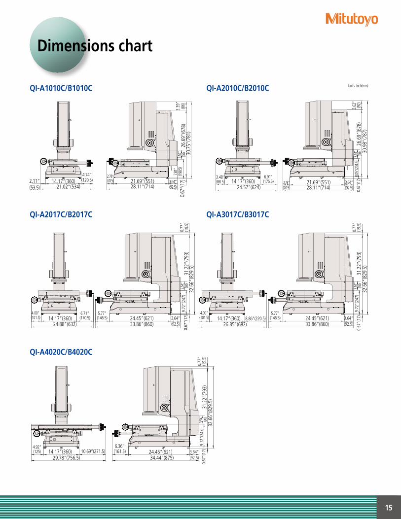
QI-A1010C/B1010C QI-A2010C/B2010C
QI-A2017C/B2017C QI-A3017C/B3017C
QI-A4020C/B4020C
Dimensions chart
Units: Inch(mm)
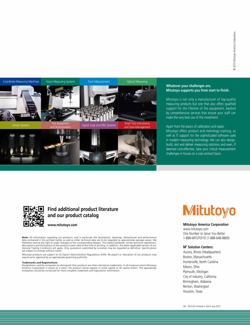
Coordinate Measuring Machines
Sensor Systems
Vision Measuring Systems
Test Equipmentand Seismometers
Form Measurement
Digital Scale and DRO Systems
Optical Measuring
Small Tool Instrumentsand Data Management
Whatever your challenges are, Mitutoyo supports you from start to finish.
Mitutoyo is not only a manufacturer of top-quality measuring products but one that also offers qualified support for the lifetime of the equipment, backed by comprehensive services that ensure your staff can make the very best use of the investment.
Apart from the basics of calibration and repair, Mitutoyo offers product and metrology training, as well as IT support for the sophisticated software used in modern measuring technology. We can also design, build, test and deliver measuring solutions and even, if deemed cost-effective, take your critical measurement challenges in-house on a sub-contract basis.
Mitutoyo America Corporationwww.mitutoyo.comOne Number to Serve You Better1-888-MITUTOYO (1-888-648-8869)
M3 Solution Centers:Aurora, Illinois (Headquarters)Boston, MassachusettsHuntersville, North CarolinaMason, OhioPlymouth, MichiganCity of Industry, CaliforniaBirmingham, AlabamaRenton, WashingtonHouston, Texas
3M 0515-02 • Printed in USA • June 2015
© 2
015
Mitu
toyo
Am
erica
Cor
pora
tion
Find additional product literature and our product catalog
www.mitutoyo.com
Note: All information regarding our products, and in particular the illustrations, drawings, dimensional and performance data contained in this printed matter as well as other technical data are to be regarded as approximate average values. We therefore reserve the right to make changes to the corresponding designs. The stated standards, similar technical regulations, descriptions and illustrations of the products were valid at the time of printing. In addition, the latest applicable version of our General Trading Conditions will apply. Only quotations submitted by ourselves may be regarded as definitive. Specifications are subject to change without notice.
Mitutoyo products are subject to US Export Administration Regulations (EAR). Re-export or relocation of our products may require prior approval by an appropriate governing authority.
Trademarks and RegistrationsDesignations used by companies to distinguish their products are often claimed as trademarks. In all instances where Mitutoyo America Corporation is aware of a claim, the product names appear in initial capital or all capital letters. The appropriate companies should be contacted for more complete trademark and registration information.