1The Democritus University of Thrace, Dept. of ...
6
22nd CIPA Symposium, October 11-15, 2009, Kyoto, Japan PHOTOGRAMMETRY AS Α ΤOOL TO RECORD A HISTORIC BUILDING AT RISK Tsioukas, V. 1 , Alexandri, V. 2∗ , Karayannis C.G. 2 , Chalioris, C.E. 2 1 The Democritus University of Thrace, Dept. of Architectural Engineering, New Building of Central Library, Kimmeria, Xanthi 67100, Greece [email protected] 2 The Democritus University of Thrace, Dept. of Civil Engineering, Vas. Sofias 12, Xanthi 67100, Greece [email protected], [email protected], [email protected] KEY WORDS: Architecture, Surveying, Photogrammetry, Close Range, Reconstruction ABSTRACT: In this paper, the use of conventional and phototogrammetric surveys is described for the recording of a historic building that has suffered significant damage and partial collapse. Through photogrammetric and conventional topographic surveys the architectural and structural characteristics and the morphological components of the building and its pathology have been recorded with an appropriate accuracy in order to have all the necessary information for the structure. This information will assist to choose the proper repairing and strengthening techniques in order to renovate and reopen the building. The widespread use of imaging and photogrammetry was necessary because a large part of the building is about to collapse and there is also a large degree of risk for all the surrounding buildings and the people moving around it. The ultimate aim is the rehabilitation and restoration of the building and its future use as a Municipal Library. Specifically, the photogrammetric procedure is used to record a tobacco warehouse in Alexandroupoli, a city of northern Greece. This is a historic building, by bearing masonry, which is an excellent example of industrial architecture influenced initially by the architecture in the late 19th century. Constructed before 1900, part of it has been fire-destroyed and through the years had different uses, such as school, tobacco store, jail and refugees’ accommodation. In 2005 after inappropriate interventions during the rehabilitation and reopening of the municipality library, part of the eastern and north wall together with a part of the roof, collapsed. The current paper describes the recording procedure as a combination of conventional topographic surveys and photogrammetric image processing for the creation of all the façades’ orthoimages thar are used as background information to digitize details of the building construction in a CAD environment. Finally, the Photomodeler software and the freeware application Hugin has been used to create respectively a detailed 3D model and an interactive panorama file of the building. ∗ Corresponding author. 1. HISTORICAL REFERENCE The exponential growth of Alexandroupoli late last century resulted on the immigration of many western catholic families. Most of them were technicians and servants at the railway, consulate staff and merchants. Based on the testimonies of old citizens of Alexandroupoli, the building was constructed before 1900 by the catholic community in order to use it as a school. In 1904, during a student exhibition, an incident of fire destroyed part of the building including its equipment and the facilities. It was reconstructed in 1924 and got its today’s form in order to be used as a tobacco warehouse. That’s why there is a sign on the gable that indicates this date as the year of the construction of the building (figure 1). The form of the building remained the same until recently, when it collapsed in 2005. At the time of its construction, it was one of the few buildings of such dimensions. Through the years, it had different uses, for the accommodation of which demanded big spaces that were very hard to find at that time. During the period of 1940, when Greece was under occupation, the building was used as a jail by the Bulgarians. After the liberation, it was used temporarily, again as a jail, and during the time of the civil war as a refugees’ accommodation. For many years, the building remained unexploited to this very day. Recently, it was bought by the municipality with the purpose of its future use as the Municipal Library. Because of a long period of neglect, the building has sustained constant Figure 1. Vintage photograph of the tobacco warehouse. The building functions as a tobacco warehouse with the corporate name “Compagnie General de Tabac”. At the top of the gable, one can see the date 1924, which is the year that the building began to function as a tobacco warehouse
Transcript of 1The Democritus University of Thrace, Dept. of ...
22nd CIPA Symposium, October 11-15, 2009, Kyoto, Japan
PHOTOGRAMMETRY AS Α ΤOOL TO RECORD A HISTORIC BUILDING AT RISK
Tsioukas, V.1, Alexandri, V.2∗, Karayannis C.G.2, Chalioris, C.E.2
1The Democritus University of Thrace, Dept. of Architectural Engineering, New Building of Central Library, Kimmeria, Xanthi 67100, Greece
[email protected] 2The Democritus University of Thrace, Dept. of Civil Engineering, Vas. Sofias 12, Xanthi 67100, Greece
[email protected], [email protected], [email protected]
KEY WORDS: Architecture, Surveying, Photogrammetry, Close Range, Reconstruction ABSTRACT: In this paper, the use of conventional and phototogrammetric surveys is described for the recording of a historic building that has suffered significant damage and partial collapse. Through photogrammetric and conventional topographic surveys the architectural and structural characteristics and the morphological components of the building and its pathology have been recorded with an appropriate accuracy in order to have all the necessary information for the structure. This information will assist to choose the proper repairing and strengthening techniques in order to renovate and reopen the building. The widespread use of imaging and photogrammetry was necessary because a large part of the building is about to collapse and there is also a large degree of risk for all the surrounding buildings and the people moving around it. The ultimate aim is the rehabilitation and restoration of the building and its future use as a Municipal Library. Specifically, the photogrammetric procedure is used to record a tobacco warehouse in Alexandroupoli, a city of northern Greece. This is a historic building, by bearing masonry, which is an excellent example of industrial architecture influenced initially by the architecture in the late 19th century. Constructed before 1900, part of it has been fire-destroyed and through the years had different uses, such as school, tobacco store, jail and refugees’ accommodation. In 2005 after inappropriate interventions during the rehabilitation and reopening of the municipality library, part of the eastern and north wall together with a part of the roof, collapsed. The current paper describes the recording procedure as a combination of conventional topographic surveys and photogrammetric image processing for the creation of all the façades’ orthoimages thar are used as background information to digitize details of the building construction in a CAD environment. Finally, the Photomodeler software and the freeware application Hugin has been used to create respectively a detailed 3D model and an interactive panorama file of the building.
∗ Corresponding author.
1. HISTORICAL REFERENCE
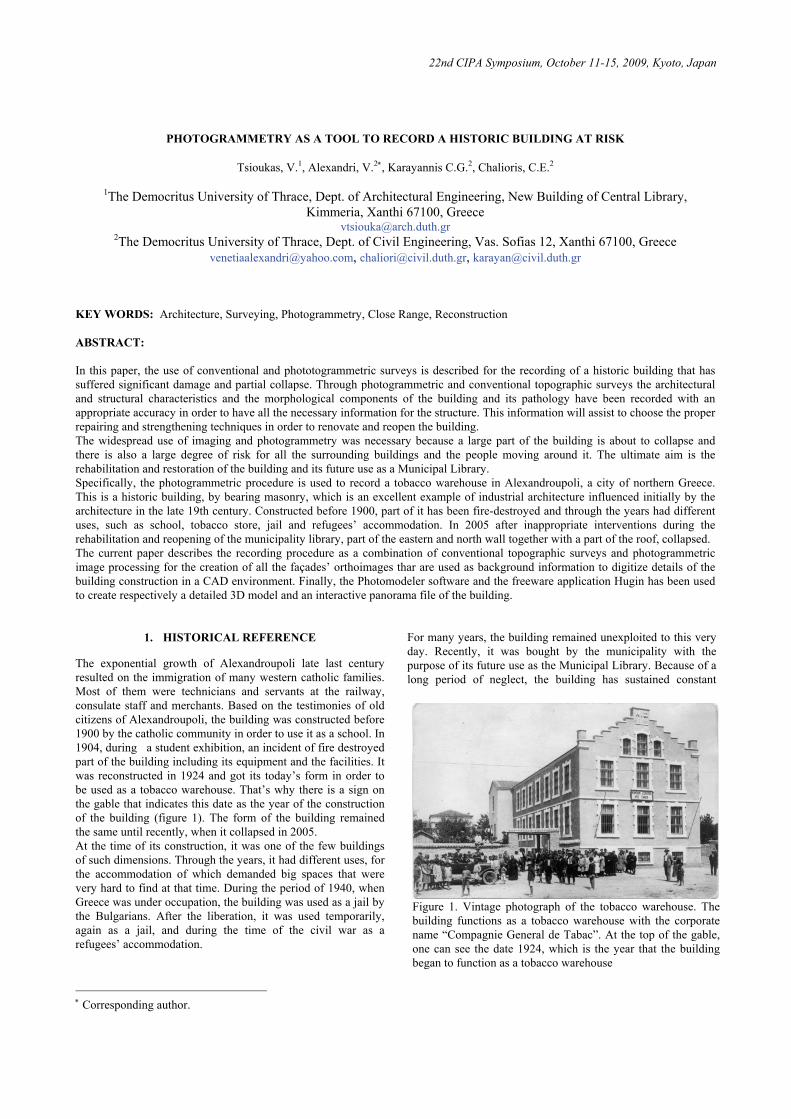
The exponential growth of Alexandroupoli late last century resulted on the immigration of many western catholic families. Most of them were technicians and servants at the railway, consulate staff and merchants. Based on the testimonies of old citizens of Alexandroupoli, the building was constructed before 1900 by the catholic community in order to use it as a school. In 1904, during a student exhibition, an incident of fire destroyed part of the building including its equipment and the facilities. It was reconstructed in 1924 and got its today’s form in order to be used as a tobacco warehouse. That’s why there is a sign on the gable that indicates this date as the year of the construction of the building (figure 1). The form of the building remained the same until recently, when it collapsed in 2005. At the time of its construction, it was one of the few buildings of such dimensions. Through the years, it had different uses, for the accommodation of which demanded big spaces that were very hard to find at that time. During the period of 1940, when Greece was under occupation, the building was used as a jail by the Bulgarians. After the liberation, it was used temporarily, again as a jail, and during the time of the civil war as a refugees’ accommodation.
For many years, the building remained unexploited to this very day. Recently, it was bought by the municipality with the purpose of its future use as the Municipal Library. Because of a long period of neglect, the building has sustained constant
Figure 1. Vintage photograph of the tobacco warehouse. Thebuilding functions as a tobacco warehouse with the corporatename “Compagnie General de Tabac”. At the top of the gable,one can see the date 1924, which is the year that the buildingbegan to function as a tobacco warehouse
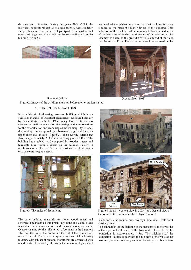
Figure 3. The inside of the building
Figure 4. South – western view in 2003 (top). General view of the tobacco storehouse after the collapse (bottom)
damages and thieveries. During the years 2004 -2005, the interventions for its rehabilitation began but they were suddenly stopped because of a partial collapse (part of the eastern and north wall together with a part of the roof collapsed) of the building (figure 5).
2. STRUCTURAL FEATURES
It is a historic loadbearing masonry building which is an excellent example of industrial architecture influenced initially by the architecture in the late 19th century. From the time it was constructed until the year 2004 (beginning of the interventions for the rehabilitation and reopening as the municipality library), the building was composed by a basement, a ground floor, an upper floor and an attic (figure 2). The covering surface per floor is approximately 293m2 in a building plot of 846m2. The building has a gabled roof, composed by wooden trusses and terracotta tiles, forming gables on the facades. Finally, it neighbours on a block of flats at the east with a blind eastern wall (no windows) as a result.
The basic building materials are stone, wood, metal and concrete. The materials that prevail are stone and wood. Metal is used at the window recesses and, in some cases, as beams. Concrete is used for the middle row of columns in the basement. The roof, the floors, the beams and the rest of the columns are made of wood. The structural system consists of loadbearing masonry with ashlars of regional granite that are connected with mood mortar. It is worthy of remark the hierarchical placement
per level of the ashlars in a way that their volume is being reduced as we reach the higher levels of the building. This reduction of the thickness of the masonry follows the reduction of the loads. In particular, the thickness of the masonry at the basement is 60cm, at the ground floor is 50cm and at the floor and the attic is 45cm. The masonries were lime – casted on the
inside and on the outside, but nowadays these lime – casts don’t exist any more. The foundation of the building is the masonry that follows the outside perimetrical walls of the basement. The depth of the foundation is approximately 1.5m. The thickness of the foundation is a little bigger than the thickness of the walls of the basement, which was a very common technique for foundations
Basement (2003)
Ground floor (2003)
Figure 2. Images of the buildings situation before the restoration started
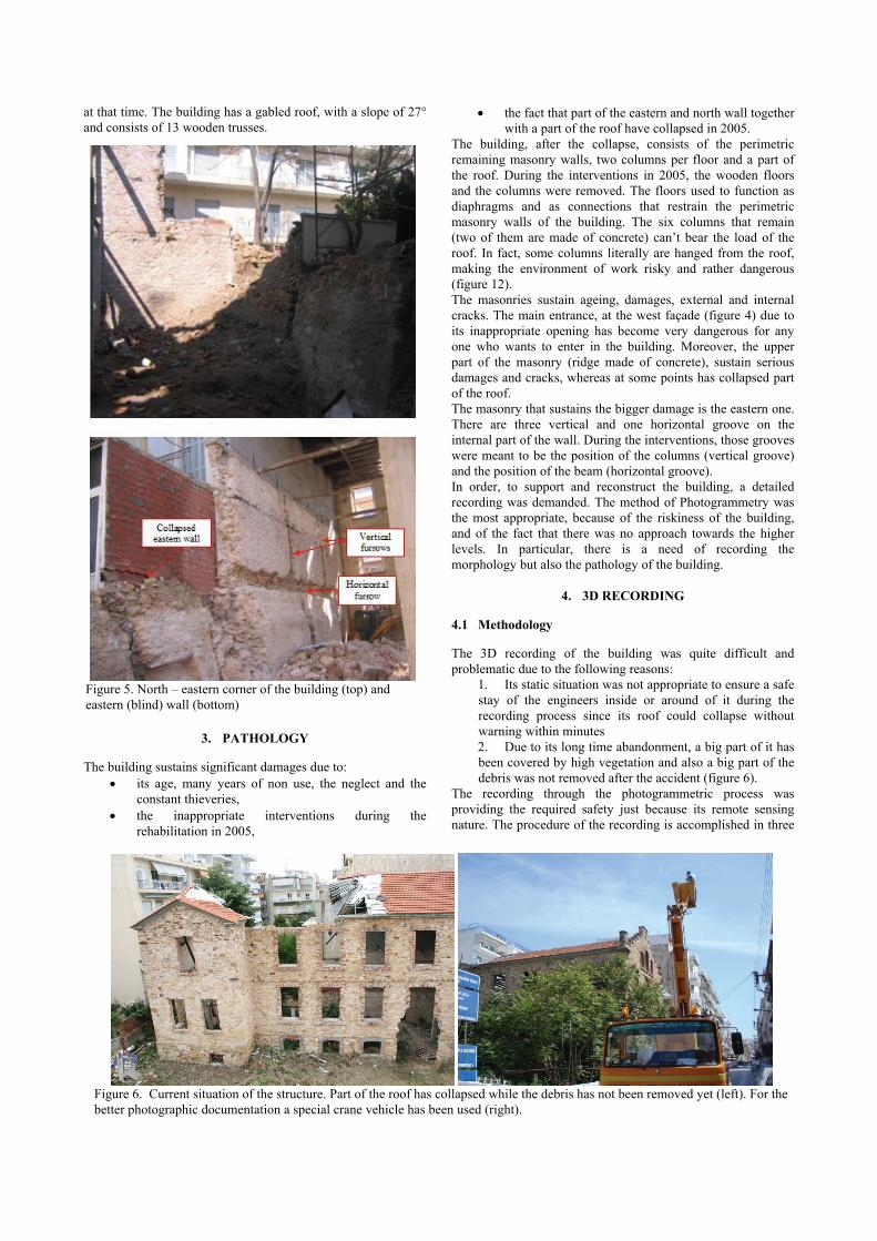
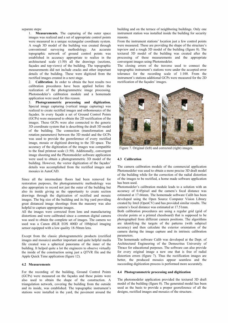
Figure 6. Current situation of the structure. Part of the roof has collapsed while the debris has not been removed yet (left). For the better photographic documentation a special crane vehicle has been used (right).
at that time. The building has a gabled roof, with a slope of 27° and consists of 13 wooden trusses.
3. PATHOLOGY
The building sustains significant damages due to: • its age, many years of non use, the neglect and the
constant thieveries, • the inappropriate interventions during the
rehabilitation in 2005,
• the fact that part of the eastern and north wall together with a part of the roof have collapsed in 2005.
The building, after the collapse, consists of the perimetric remaining masonry walls, two columns per floor and a part of the roof. During the interventions in 2005, the wooden floors and the columns were removed. The floors used to function as diaphragms and as connections that restrain the perimetric masonry walls of the building. The six columns that remain (two of them are made of concrete) can’t bear the load of the roof. In fact, some columns literally are hanged from the roof, making the environment of work risky and rather dangerous (figure 12). The masonries sustain ageing, damages, external and internal cracks. The main entrance, at the west façade (figure 4) due to its inappropriate opening has become very dangerous for any one who wants to enter in the building. Moreover, the upper part of the masonry (ridge made of concrete), sustain serious damages and cracks, whereas at some points has collapsed part of the roof. The masonry that sustains the bigger damage is the eastern one. There are three vertical and one horizontal groove on the internal part of the wall. During the interventions, those grooves were meant to be the position of the columns (vertical groove) and the position of the beam (horizontal groove). In order, to support and reconstruct the building, a detailed recording was demanded. The method of Photogrammetry was the most appropriate, because of the riskiness of the building, and of the fact that there was no approach towards the higher levels. In particular, there is a need of recording the morphology but also the pathology of the building.
4. 3D RECORDING
4.1 Methodology
The 3D recording of the building was quite difficult and problematic due to the following reasons:
1. Its static situation was not appropriate to ensure a safe stay of the engineers inside or around of it during the recording process since its roof could collapse without warning within minutes 2. Due to its long time abandonment, a big part of it has been covered by high vegetation and also a big part of the debris was not removed after the accident (figure 6).
The recording through the photogrammetric process was providing the required safety just because its remote sensing nature. The procedure of the recording is accomplished in three
Figure 5. North – eastern corner of the building (top) and eastern (blind) wall (bottom)
separate steps: 1. Measurements. The capturing of the outer space images was realized and a set of appropriate control points were measured in a unique rectangular coordinate system. A rough 3D model of the building was created through conventional surveying methodology. An accurate topographic network of ground control points was established in accuracy appropriate to realize in the architectural scale (1:50) all the drawings (sections, façades and top-views) of the building. The topographic measurements did not include cracks and other important details of the building. These were digitized from the rectified images created in a next stage. 2. Calibration. In order to obtain the best results two calibration procedures have been applied before the realization of the photogrammetric image processing. Photomodeler’s calibration module and a homemade application were used for this reason. 3. Photogrammetric processing and digitization. Special image capturing (vertical image capturing) was realized to create rectified images and orthomosaics of the façades. In every façade a set of Ground Control Points (GCPs) were measured to obtain the 2D rectification of the images. These GCPs were also connected to the generic 3D coordinate system that is describing the draft 3D model of the building. The connection (transformation and rotation parameters) between the 3D model and the GCPs was used to provide the georeference of every rectified image, mosaic or digitized drawing to the 3D space. The accuracy of the digitization of the images was compatible to the final printout scale (1:50). Additionally, convergent image shooting and the Photomodeler software application were used to obtain a photogrammetric 3D model of the building. However, the vector digitization of the façades’ details was accomplished from the rectified images and mosaics in AutoCAD.
Since all the intermediate floors had been removed for restoration purposes, the photogrammetric methodology was also appropriate to record not just the outer of the building but also its inside giving us the opportunity to create section drawings through the digitization of rectified and mosaic images. The big size of the building and its big yard providing great distanced image shootings from the masonry was also helpful to capture appropriate images. All the images were corrected from lens and manufacturing distortions and were calibrated since a common digital camera was used to obtain the complete set of images. The camera we used was a Canon dSLR EOS 400D of 10Mpixel imaging sensor equipped with a low quality 18-50mm lens. Except from the classic photogrammetric products (rectified images and mosaics) another important and quite helpful media file created was a spherical panorama of the inner of the building. It helped quite a lot the engineers to observe virtually the inside of the construction using just a QTVR file and the Apple Quick Time application (figure 12). 4.2 Measurements
For the recording of the building, Ground Control Points (GCPs) were measured on the façades and these points were also used to obtain the shape of the construction. A triangulation network, covering the building from the outside and its inside, was established. The topographic instrument’s stations were installed in the yard, the pavement around the
building and on the terrace of neighboring buildings. Only one instrument station was installed inside the building for security reasons. From the instrument stations’ location just a few control points were measured. These are providing the shape of the structure’s topview and a rough 3D model of the building (figure 8). The textured 3D model of the building was created after the processing of these measurements and the appropriate convergent images using Photomodeler. The closing errors of the traverse used to connect the topographic instrument’s stations were under the accepted error tolerance for the recording scale of 1:100. From the instrument’s stations additional GCPs were measured for the 2D rectification of the façades’ images.
4.3 Calibration
The camera calibration module of the commercial application Photomodeler was used to obtain a more precise 3D draft model of the building while for the correction of the radial distortion of the images to be rectified, a home made software application has been used. Photomodeler’s calibration module leads to a solution with an accuracy of 0.45pixel and the camera’s focal distance was estimated at 17.66mm. The homemade software Calib has been developed using the Open Source Computer Vision Library created by Intel (OpenCV) and has provided similar results. The camera’s focal distance was estimated at 17.51mm. Both calibration procedures are using a regular grid (grid of circular points or a printed chessboard) that is supposed to be photographed from different camera positions. The algorithms are identifying the targets of the patterns (with subpixel accuracy) and then calculate the exterior orientation of the camera during the image capture and its intrinsic calibration parameters. The homemade software Calib was developed at the Dept. of Architectural Engineering of the Democritus University of Thrace for educational purposes. The software can also provide for every original image a new one that is free of radial distortion errors (figure 7). Thus the rectification images are better, the produced mosaics appear seamless and the succeeding digitization process is performed more accurately. 4.4 Photogrammetric processing and digitization
The photomodeler application provided the textured 3D draft model of the building (figure 8). The generated model has been used as the basis to provide a proper georeference of all the designs, rectified images and mosaics of the structure.
Figure 7. Original (left) and corrected (right) images.
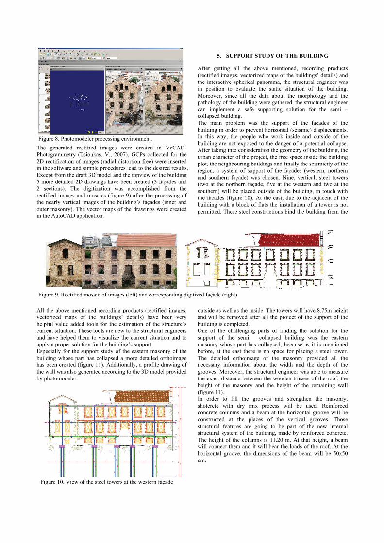
The generated rectified images were created in VeCAD-Photogrammetry (Tsioukas, V., 2007). GCPs collected for the 2D rectification of images (radial distortion free) were inserted in the software and simple procedures lead to the desired results. Except from the draft 3D model and the topview of the building 5 more detailed 2D drawings have been created (3 façades and 2 sections). The digitization was accomplished from the rectified images and mosaics (figure 9) after the processing of the nearly vertical images of the building’s façades (inner and outer masonry). The vector maps of the drawings were created in the AutoCAD application.
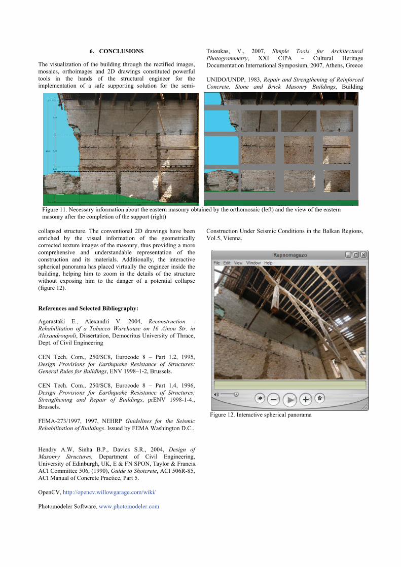
All the above-mentioned recording products (rectified images, vectorized maps of the buildings’ details) have been very helpful value added tools for the estimation of the structure’s current situation. These tools are new to the structural engineers and have helped them to visualize the current situation and to apply a proper solution for the building’s support. Especially for the support study of the eastern masonry of the building whose part has collapsed a more detailed orthoimage has been created (figure 11). Additionally, a profile drawing of the wall was also generated according to the 3D model provided by photomodeler.
5. SUPPORT STUDY OF THE BUILDING
After getting all the above mentioned, recording products (rectified images, vectorized maps of the buildings’ details) and the interactive spherical panorama, the structural engineer was in position to evaluate the static situation of the building. Moreover, since all the data about the morphology and the pathology of the building were gathered, the structural engineer can implement a safe supporting solution for the semi – collapsed building. The main problem was the support of the facades of the building in order to prevent horizontal (seismic) displacements. In this way, the people who work inside and outside of the building are not exposed to the danger of a potential collapse. After taking into consideration the geometry of the building, the urban character of the project, the free space inside the building plot, the neighbouring buildings and finally the seismicity of the region, a system of support of the façades (western, northern and southern façade) was chosen. Nine, vertical, steel towers (two at the northern façade, five at the western and two at the southern) will be placed outside of the building, in touch with the facades (figure 10). At the east, due to the adjacent of the building with a block of flats the installation of a tower is not permitted. These steel constructions bind the building from the
outside as well as the inside. The towers will have 8.75m height and will be removed after all the project of the support of the building is completed. One of the challenging parts of finding the solution for the support of the semi – collapsed building was the eastern masonry whose part has collapsed, because as it is mentioned before, at the east there is no space for placing a steel tower. The detailed orthoimage of the masonry provided all the necessary information about the width and the depth of the grooves. Moreover, the structural engineer was able to measure the exact distance between the wooden trusses of the roof, the height of the masonry and the height of the remaining wall (figure 11). In order to fill the grooves and strengthen the masonry, shotcrete with dry mix process will be used. Reinforced concrete columns and a beam at the horizontal groove will be constructed at the places of the vertical grooves. Those structural features are going to be part of the new internal structural system of the building, made by reinforced concrete. The height of the columns is 11.20 m. At that height, a beam will connect them and it will bear the loads of the roof. At the horizontal groove, the dimensions of the beam will be 50x50 cm.
Figure 8. Photomodeler processing environment.
Figure 9. Rectified mosaic of images (left) and corresponding digitized façade (right)
Figure 10. View of the steel towers at the western façade
6. CONCLUSIONS
The visualization of the building through the rectified images, mosaics, orthoimages and 2D drawings constituted powerful tools in the hands of the structural engineer for the implementation of a safe supporting solution for the semi-
collapsed structure. The conventional 2D drawings have been enriched by the visual information of the geometrically corrected texture images of the masonry, thus providing a more comprehensive and understandable representation of the construction and its materials. Additionally, the interactive spherical panorama has placed virtually the engineer inside the building, helping him to zoom in the details of the structure without exposing him to the danger of a potential collapse (figure 12).
References and Selected Bibliography:
Agorastaki E., Alexandri V. 2004, Reconstruction – Rehabilitation of a Tobacco Warehouse on 16 Ainou Str. in Alexandroupoli, Dissertation, Democritus University of Thrace, Dept. of Civil Engineering CEN Tech. Com., 250/SC8, Eurocode 8 – Part 1.2, 1995, Design Provisions for Earthquake Resistance of Structures: General Rules for Buildings, ENV 1998–1-2, Brussels. CEN Tech. Com., 250/SC8, Eurocode 8 – Part 1.4, 1996, Design Provisions for Earthquake Resistance of Structures: Strengthening and Repair of Buildings, prENV 1998-1-4., Brussels. FEMA-273/1997, 1997, NEHRP Guidelines for the Seismic Rehabilitation of Buildings. Issued by FEMA Washington D.C.. Hendry A.W, Sinha B.P., Davies S.R., 2004, Design of Masonry Structures, Department of Civil Engineering, University of Edinburgh, UK, E & FN SPON, Taylor & Francis. ACI Committee 506, (1990), Guide to Shotcrete, ACI 506R-85, ACI Manual of Concrete Practice, Part 5. OpenCV, http://opencv.willowgarage.com/wiki/ Photomodeler Software, www.photomodeler.com
Tsioukas, V., 2007, Simple Tools for Architectural Photogrammetry, ΧXI CIPA – Cultural Heritage Documentation International Symposium, 2007, Athens, Greece UNIDO/UNDP, 1983, Repair and Strengthening of Reinforced Concrete, Stone and Brick Masonry Buildings, Building
Construction Under Seismic Conditions in the Balkan Regions, Vol.5, Vienna.
Figure 11. Necessary information about the eastern masonry obtained by the orthomosaic (left) and the view of the eastern masonry after the completion of the support (right)
Figure 12. Interactive spherical panorama