
18 11 23 Battery Script - chemgeo.uni-jena.de
17
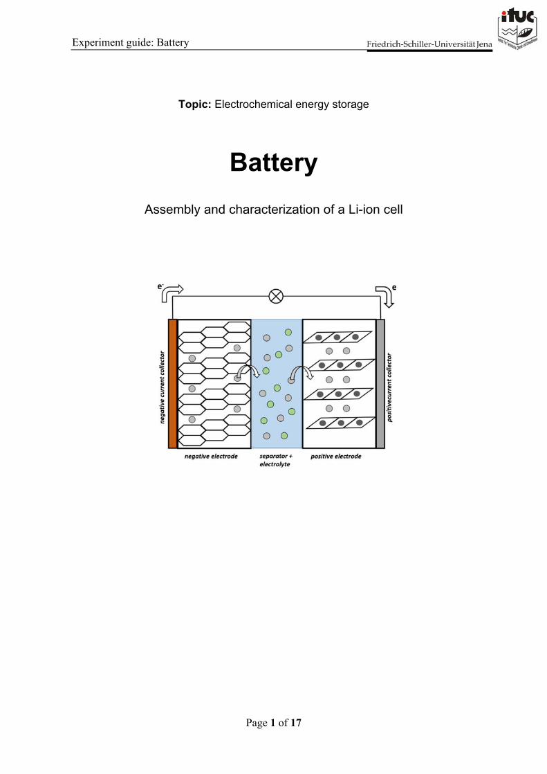
Page 1 of 17 Experiment guide: Battery Topic: Electrochemical energy storage Battery Assembly and characterization of a Li-ion cell
Transcript of 18 11 23 Battery Script - chemgeo.uni-jena.de
Page 1 of 17
Experiment guide: Battery
Topic: Electrochemical energy storage
Battery
Assembly and characterization of a Li-ion cell

Page 2 of 17
Experiment guide: Battery
Learning targets:
1. Understanding the workwise of an electrochemical Li-ion cell
2. Getting practical experience in electrode preparation and cell assembly
3. Learning to work with gloveboxes properly
4. Analyzing galvanostatic cell-cycling data correctly
Page 3 of 17
Experiment guide: Battery
Parameters, constants & abbreviations – a selection
ΔrG Gibbs free enthalpy in kJ mol−1
z Number of charges per reaction equivalent
F Faraday constant: 96485 A s mol−1
E Cell voltage in V
µ Electrochemical potential in kJ mol−1
R Gas constant: 8.3145 J mol−1 K−1
T Temperature in K
a Activity in mol L−1
qth theoretical capacity in mA h g−1
m Mass of active material in mg
M Molar mass of active material in g mol−1
ηc Coulombic efficiency
qdis Discharge capacity in mA h g−1
qch Charge capacity in mA h g−1
ηE Energy efficiency
Edis Discharge cell voltage in V
Ech Charge cell voltage in V
SEI Solid electrolyte interphase
VC Vinylenecarbonate
FEC Fluoroethylenecarbonate
CE Counter electrode
RE Reference electrode
WE Working electrode
CB Carbon black
PVDF Polyvinylidenefluorid
NMP N-methyl-pyrrolidone
GCPL Galvanostatic cycling with potential limits
Page 4 of 17
Experiment guide: Battery
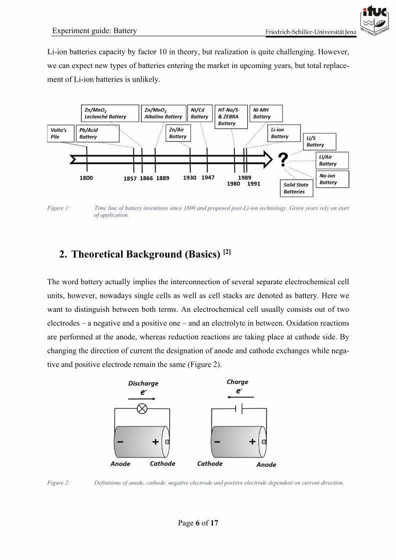
1. Introduction [1]-[5] (not necessary for experiment and colloquia)
The subject electrochemistry is often associated with the conversion of chemical energy into
electricity and the other way around. Storing and releasing energy on demand, in fact, this is
what modern batteries are supposed to do for powering our electro vehicles and consumer elec-
tronics. But, it was a long way from first observations and usage of chemical electricity to Li-
ion batteries we know today. Historically documented is the 2000 years old “Bagdad battery”.
This was a salt water filled clay jar with copper and iron metal electrodes inside. Although, the
identity as electrochemical device is proven, discussions about its purpose remain. Possible
applications were kind of electro therapy or early galvanic processes with noble metal deposi-
tion. Another example is the “lemon battery”, a famous school experiment, which follows sim-
ilar workwise. By putting two different metals inside the lemon an electrical voltage of around
1 V appears. Both approaches are easy to realize but, of course, they fail in terms of being a
reliable power device, let alone the missing rechargeability. In the end of 18th century ALES-
SANDRO VOLTA developed the Volta Pile – a stack of alternating zinc and copper plates.
The plates were separated from each other by wet towels and were electrically connected by
wires. For the first time a sustainable direct current source was available and fast research pro-
gress with this revolutionary tool took over: As an example, electrochemical water splitting was
discovered and analyzed by the British scientists NICHOLSON and CHARLISLE in 1800 –
the same year VOLTA presented his invention in London. 30 years later MICHAEL FARA-
DAY introduced a couple of still valid definitions: anode, cathode, anion, cation, electrolyte
and electrolysis. Without doubt, the Volta Pile can be denoted as first commercially available
battery in history, but it was heavy, expensive and still not rechargeable. However, myriads of
electrochemical explorations were obtained by using this electricity source.
First rechargeable device was invented in 1857 by PLANTE – the lead acid battery. This system
exhibits a high reversibility, good temperature tolerance and an output voltage of 2 V per cell
unit. Pb-acid batteries were and are of high relevance especially for automotive applications.
Hence, Pb-acid systems are still the second biggest participant on world battery market today.
One decade later LECLANCHE developed a system based on the irreversible reaction of zinc
and MnO2. The so called Leclanché element was an early version of 1.5 V alkaline batteries we
know today. These portable alkaline dry cells were invented independently by YAI, WILHELM
and HELLESEN around 1889. Zinc air batteries, we know as tiny coin cells for hearing devices,
were developed in 1930s but the designation as fuel cell would be more appropriate due to zinc
Page 5 of 17
Experiment guide: Battery
combustion by air-oxygen. Taking together lead and zinc were the most important elements
towards serving as electrochemical energy source for quite a long time.
Ni/Cd-systems were already investigated by JUNGNER in 1890 but the technology had its
breakthrough only in 1947, when it was designed as portable, rechargeable and closed device.
Because of its materials toxicity Ni/Cd accumulators are prohibited in European Union since
2004.
High temperature batteries (̴ 300°C) are usually considered for stationary energy storage and
were promoted in late 1970s by the invention of Na-β´´- aluminate – a high performance Na-
ion conductor. Representatives are the Na/NiCl2- (ZEBRA) and the Na/S-battery so one may
say that Na-devices are much older than Li-based ones.
In late 1980s Nickel-metal hydride (Ni-MH) batteries were the rechargeable answer on one way
zinc alkaline batteries. They had the same format, similar properties and were able to power the
first portable computers without exchange of power supply. Ni-MH batteries are still widely in
use, for example in hybrid cars.
In 1991 SONY finally introduced the first mass product Li-ion battery on the market. The rev-
olutionary invention outperformed former technologies in several categories (energy, power,
life time) and conquered the market of consumer electronics rapidly. Former Ni/Cd and Ni/MH
batteries were quickly superseded. The first Li-ion battery contained graphite and LiCoO2 as
electrodes. Although there was a lot of progress in battery optimization in last decades, the
general workwise of Li-ion batteries did not change yet. Nowadays, the main challenge of bat-
teries is the promoting subject electro mobility. TESLA, SAMSUNG, SONY, PANASONIC
and CATL, to mention a few of world biggest battery producers, are preparing to face this
challenge and battery production is expected to rise by 2000% until 2030. An example for these
ambitions is the construction of TESLAs and PANASONICs Gigafactory in Nevada. Recently,
CATL has announced the construction of a production plant not far away from here, in Erfurt.
A Li-ion-battery currently provides an energy density of 160 Wh kg-1 and a specific capacity
of around 40 Ah kg-1. These values are already close to the theoretical maximum and further
improvement might lead to serious safety drawbacks. In other words: Li-ion technology is fac-
ing its technical limits. One may remember the SAMSUNG Note 7 problem in 2016, when
several devices caught accidentally fire. Therefore, by projecting better performance conceptual
change is necessary. Candidates for so called post-Li-ion batteries are all solid state approaches,
which promise better safety and volumetric energy density or Na-ion batteries containing more
abundant materials. The utilization of oxygen or sulfur as electrode material would outperform
Page 6 of 17
Experiment guide: Battery
Li-ion batteries capacity by factor 10 in theory, but realization is quite challenging. However,
we can expect new types of batteries entering the market in upcoming years, but total replace-
ment of Li-ion batteries is unlikely.
Figure 1: Time line of battery inventions since 1800 and proposed post-Li-ion technology. Given years rely on start of application.
2. Theoretical Background (Basics) [2]
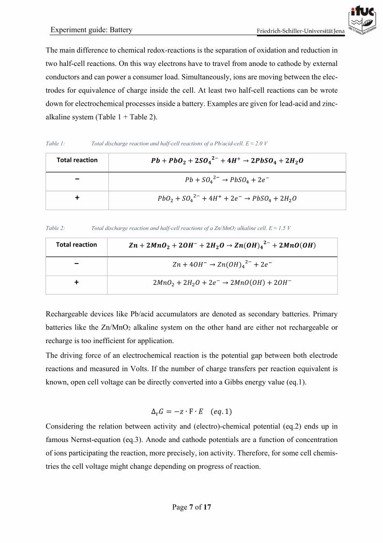
The word battery actually implies the interconnection of several separate electrochemical cell
units, however, nowadays single cells as well as cell stacks are denoted as battery. Here we
want to distinguish between both terms. An electrochemical cell usually consists out of two
electrodes – a negative and a positive one – and an electrolyte in between. Oxidation reactions
are performed at the anode, whereas reduction reactions are taking place at cathode side. By
changing the direction of current the designation of anode and cathode exchanges while nega-
tive and positive electrode remain the same (Figure 2).
Figure 2: Definitions of anode, cathode, negative electrode and positive electrode dependent on current direction.
Page 7 of 17
Experiment guide: Battery
The main difference to chemical redox-reactions is the separation of oxidation and reduction in
two half-cell reactions. On this way electrons have to travel from anode to cathode by external
conductors and can power a consumer load. Simultaneously, ions are moving between the elec-
trodes for equivalence of charge inside the cell. At least two half-cell reactions can be wrote
down for electrochemical processes inside a battery. Examples are given for lead-acid and zinc-
alkaline system (Table 1 + Table 2).
Table 1: Total discharge reaction and half-cell reactions of a Pb/acid-cell. E ≈ 2.0 V
Total reaction 𝑷𝒃 𝑷𝒃𝑶𝟐 𝟐𝑺𝑶𝟒𝟐 𝟒𝑯 → 𝟐𝑷𝒃𝑺𝑶𝟒 𝟐𝑯𝟐𝑶
− 𝑃𝑏 𝑆𝑂 → 𝑃𝑏𝑆𝑂 2𝑒
+ 𝑃𝑏𝑂 𝑆𝑂 4𝐻 2𝑒 → 𝑃𝑏𝑆𝑂 2𝐻 𝑂
Table 2: Total discharge reaction and half-cell reactions of a Zn/MnO2 alkaline cell. E ≈ 1.5 V
Total reaction 𝒁𝒏 𝟐𝑴𝒏𝑶𝟐 𝟐𝑶𝑯 𝟐𝑯𝟐𝑶 → 𝒁𝒏 𝑶𝑯 𝟒𝟐 𝟐𝑴𝒏𝑶 𝑶𝑯
− 𝑍𝑛 4𝑂𝐻 → 𝑍𝑛 𝑂𝐻 2𝑒
+ 2𝑀𝑛𝑂 2𝐻 𝑂 2𝑒 → 2𝑀𝑛𝑂 𝑂𝐻 2𝑂𝐻
Rechargeable devices like Pb/acid accumulators are denoted as secondary batteries. Primary
batteries like the Zn/MnO2 alkaline system on the other hand are either not rechargeable or
recharge is too inefficient for application.
The driving force of an electrochemical reaction is the potential gap between both electrode
reactions and measured in Volts. If the number of charge transfers per reaction equivalent is
known, open cell voltage can be directly converted into a Gibbs energy value (eq.1).
∆ 𝐺 𝑧 ∙ F ∙ 𝐸 𝑒𝑞. 1
Considering the relation between activity and (electro)-chemical potential (eq.2) ends up in
famous Nernst-equation (eq.3). Anode and cathode potentials are a function of concentration
of ions participating the reaction, more precisely, ion activity. Therefore, for some cell chemis-
tries the cell voltage might change depending on progress of reaction.
Page 8 of 17
Experiment guide: Battery
µ µ , R ∙ 𝑇 ∙ ln 𝑎 𝑒𝑞. 2
𝐸 𝜑 , 𝜑 ,R ∙ 𝑇𝑧 ∙ F
∙ ln𝑎 ,
𝑎 , 𝑒𝑞. 3
Besides thermodynamic view different kinetic phenomena are taking place while cycling a cell
and overpotentials are often associated with this electrochemical kinetics. Different overpoten-
tials caused by charge transfer, ohm-resistance or diffusion are known and all of them result in
efficiency losses. Consequence is that the required voltage for charging is always higher than
given voltage during discharge.
3. Li-ion Batteries: Structure and Materials [2], [3]
During charge and discharge of a Li-ion battery Li+ is released by one electrode and simultane-
ously stored by the other one. Other ions are not participating the reactions as it is the case for
many aqueous systems, so the reaction equations are easier, at least on paper (Table 3).
Negative electrodes exhibit a low potential vs. Li/Li+ and commonly consist out of graphite as
proven active material. Stoichiometrically, six carbon atoms are able to store 1 Li+-ion at po-
tentials close to 0 V vs. Li/Li+ ending up in a specific capacity of 372 mAh g−1. Besides graph-
ite, several more options are discussed (Table 4). Especially silicon and Li-metal are very at-
tractive due to their outperforming theoretical capacity but they face some issues in terms of
stability. Negative electrodes are hold together by a polymeric binder and are usually carried
by a copper current collector. Less noble metals would react with electrodes active material.
As the cell voltage is made out of the potential gap between both electrodes, positive electrodes
exhibit very high potentials of around ̴ 4 V vs. Li/Li+ (Table 4). Material class of choice in
commercial batteries are layered transition metal oxides and most known representative is
LiCoO2, which was discovered by Mizushima and Goodenough in 1980 and promoted the fast
development of Li-ion batteries. Inside these layered oxides Li+ is stored either in prismatic or
octahedral coordination. Towards better lifetime, these materials are lithiated and delithiated
incompletely; taking the example of LCO, only 0.5 Li+-ions can be reversibly stored for each
reaction equivalent. Modern positive electrodes are trying to replace more and more cobalt by
abundant metals like manganese, nickel and aluminum. Examples for non-layered oxide elec-
Page 9 of 17
Experiment guide: Battery
trodes are LiFePO4 or Li2S, which follow other storage mechanisms. Like negative ones posi-
tive electrodes are hold together by polymeric binder on top of a current collector; here alumi-
num is used. Often the active materials of positive electrodes have poor electronic conductivity,
so carbon needs to be added as conductive support.
Table 3: Total discharge reaction and half-cell reactions of Li-ion battery using Graphite and LiCoO2. E ≈ 4.0 V
Total reaction 𝑳𝒊𝑪𝟔 𝟐𝑳𝒊𝟎.𝟓𝑪𝒐𝑶𝟐 → 𝟔𝑪 𝟐𝑳𝒊𝑪𝒐𝑶𝟐
− 𝐿𝑖𝐶 → 𝐿𝑖 6𝐶 𝑒
+ 2𝐿𝑖 . 𝐶𝑜𝑂 𝐿𝑖 𝑒 → 2𝐿𝑖𝐶𝑜𝑂
Liquid electrolytes based on organic solvents and conduction salts enable the Li+-ion transport
between the electrodes. Nearly all Li-ion batteries make use of carbonate electrolytes and the
most suitable composition is a 1:1 mixture of ethylenecarbonate (EC) and dimethylcarbonate
(DMC). Conduction salt of choice is often LiPF6 in concentrations > 1M; ionic conductivity
values are in range of a few mS cm−1. For preventing electrodes from getting contact with each
other a mechanical separation foil is implemented between them. The foil is less than 25 µm
thick, whereas the electrodes score several 100 µm.
Table 4: Various electrode and electrolyte materials for Li-ion batteries
Electrode materials Electrolyte materials
Negative Positive Solvents Salts
‐ Graphite
‐ Hard car-bon (HC)
‐ Li-metal
‐ Silicon
‐ Li4Ti5O12 (LTO)
‐ LiCoO2 (LCO)
‐ LiFePO4 (LFP)
‐ LiMn2O4 (LMO)
‐ LiNi1-x-yCoxAlyO2 (NCA)
‐ LiNi1-x-yCoxMnyO2 (NMC)
‐ Ethylenecarbonate (EC)
‐ Dimethyl-carbonate (DMC)
‐ Propylenecarbonate (PC)
‐ Diethylcarbonate (DEC)
‐ LiPF6
‐ LiBF4
‐ Li-Triflate (Li-OTf)
‐ Li-trifluoro-sul-fonimide (LiTFSI)
Page 10 of 17
Experiment guide: Battery
There is no known organic solvent, which has thermodynamic stability against the potentials
occurring in a Li-ion battery. So actually the cell is supposed to degrade at electrode/electrolyte
interfaces. Nevertheless, electrodes are operating reversibly. How is this possible? The answer
is the formation of a suitable solid electrolyte interphase (SEI) during the first cycles. Indeed,
electrolyte will be decomposed but in a controlled manner resulting in a thin film of about 10-
100 nm, which is passivating the electrode against further reaction with electrolyte. Simultane-
ously, Li-ions are still able to pass this film.
Hence, the SEI film consists out of decomposition products induced by side reactions of elec-
trolyte at electrodes surface. Because of 3-dimensional character SEI has to be understood as
interphase rather than interface. Of course, not every electrolyte provides beneficial SEI for-
mation. In this regard carbonate type solvents were identified as best choice, so far. However,
modern electrolytes contain a cocktail of additives like vinylenecarbonate (VC) and fluoroeth-
ylenecarbonate (FEC) aiming in better SEI formation control.
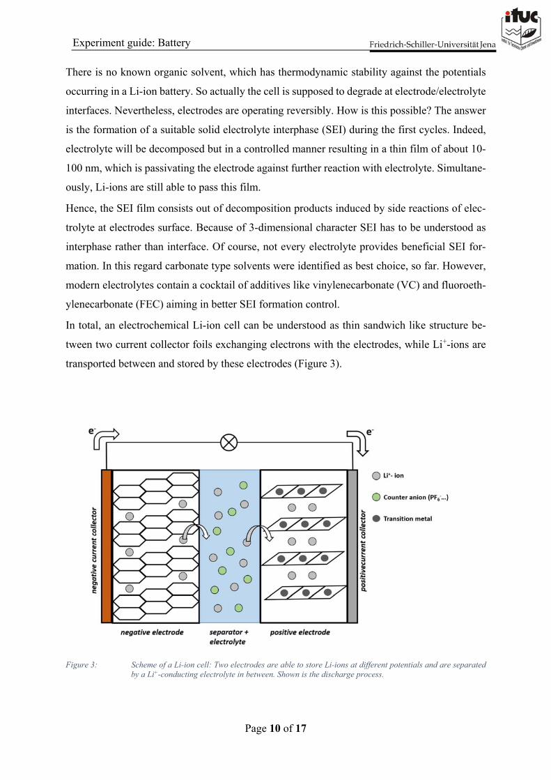
In total, an electrochemical Li-ion cell can be understood as thin sandwich like structure be-
tween two current collector foils exchanging electrons with the electrodes, while Li+-ions are
transported between and stored by these electrodes (Figure 3).
Figure 3: Scheme of a Li-ion cell: Two electrodes are able to store Li-ions at different potentials and are separated by a Li+-conducting electrolyte in between. Shown is the discharge process.
Page 11 of 17
Experiment guide: Battery
4. Li-ion batteries: Electrochemical Characterization
Towards characterization of single electrode materials it is useful to arrange a 3-electrode cell
design: counter electrode (CE), reference electrode (RE), and working electrode (WE) whereas
the WE contains the material of interest and limits the charge which can be stored inside the
cell. CE and RE are usually made out of Li-metal. A various number of electrochemical meth-
ods is available for detailed characterization of an electrochemical cell. Because some methods
are investigated separately during lab course and due to limited time we want to focus on eval-
uation of galvanostatic cycling (GCPL) in this experiment. A simple cycling curve, obtained
by applying a defined current rate, reveals already a lot of information about cell chemistry and
cell performance. An important property of an electrode material is the theoretical capacity:
Which amount of charge per gram can be stored? If the exact reaction formula is known, the
theoretical capacity can be calculated by equation 4 and is usually wrote down in Ah kg−1.
Comparing this value with experimental discharge data reveals the capacity yield of an elec-
trode material.
𝑞 𝑚 ∙ 𝑧 ∙ F
M 𝑒𝑞. 4
Efficiency values are of high relevance to evaluate further the conversion of energy and charge
storage inside an electrochemical cell. Two efficiencies can be distinguished from each other:
Coulombic efficiency ηc and energy efficiency ηE. ηc is nothing else than the comparison of
discharge capacity with former charge capacity (eq. 5). Deviations from 100% can indicate side
reactions like SEI formation or irreversible loss of active material, for example.
𝜂 𝑞
𝑞 𝑒𝑞. 5
While ηc considers charge amounts only, ηE takes additionally voltage into account (eq. 6). The
integration of voltage over capacity directly results in an energy value. Of course, charging
requires always more electrical energy than the system can release in following discharge step.
This relation is given by ηE, which is mainly influenced by overpotential effects.
𝜂𝐸 d𝑞 𝐸 d𝑞
𝑒𝑞. 6
Page 12 of 17
Experiment guide: Battery
The voltage profile itself provides already information about reaction mechanisms taking place
at working electrode. As mentioned in 3. electrode materials can either perform insertion reac-
tions or conversion reactions. Because µ does not change in terms of part by part conversion of
a material, the voltage profile is expected to have plateau like character. Insertion materials on
the other hand exhibit solid solution behavior. µ changes with ongoing lithiation and voltage
profile ends up with sloping shape.
5. Experimental Section
This experiment includes the preparation of two electrode films and testing of these electrodes
in 3-electrode, half-cell configuration. The cells will be assembled under inert conditions inside
an argon filled glovebox. Electrochemical properties will be measured by using galvanostatic
cycling protocol.
5.1 Part 1: Electrode Preparation Three battery active materials are available: LiFePO4, LiCoO2 and Graphite. Two of them need
to be chosen. Besides the active material, conductive carbon black (CB) and binder solution is
required. The binder solution is poly-vinyldifluoride (PVDF) dissolved in N-methyl-pyrroli-
done (NMP) - (50 mg mL-1). Electrode preparation starts with mixing defined amounts of active
material, CB and PVDF inside a 5 mL glass vial with magnetic stirrer. Choose the following
mass compositions:
‐ 170 mg LiFePO4, LiCoO2 or Graphite ‐ 20 mg CB ‐ 10 mg PVDF
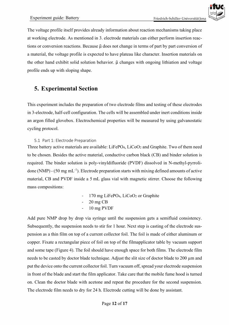
Add pure NMP drop by drop via syringe until the suspension gets a semifluid consistency.
Subsequently, the suspension needs to stir for 1 hour. Next step is casting of the electrode sus-
pension as a thin film on top of a current collector foil. The foil is made of either aluminum or
copper. Fixate a rectangular piece of foil on top of the filmapplicator table by vacuum support
and some tape (Figure 4). The foil should have enough space for both films. The electrode film
needs to be casted by doctor blade technique. Adjust the slit size of doctor blade to 200 µm and
put the device onto the current collector foil. Turn vacuum off, spread your electrode suspension
in front of the blade and start the film applicator. Take care that the mobile fume hood is turned
on. Clean the doctor blade with acetone and repeat the procedure for the second suspension.
The electrode film needs to dry for 24 h. Electrode cutting will be done by assistant.
Page 13 of 17
Experiment guide: Battery
Attention: N-methyl-pyrrolidone is toxic! Lab coat, safety goggles and gloves are mandatory!
Handle NMP with fume hood, only!
Figure 4: Filmapplicator table with doctor blade
5.2 Part 2: Cell Assembly and Characterization
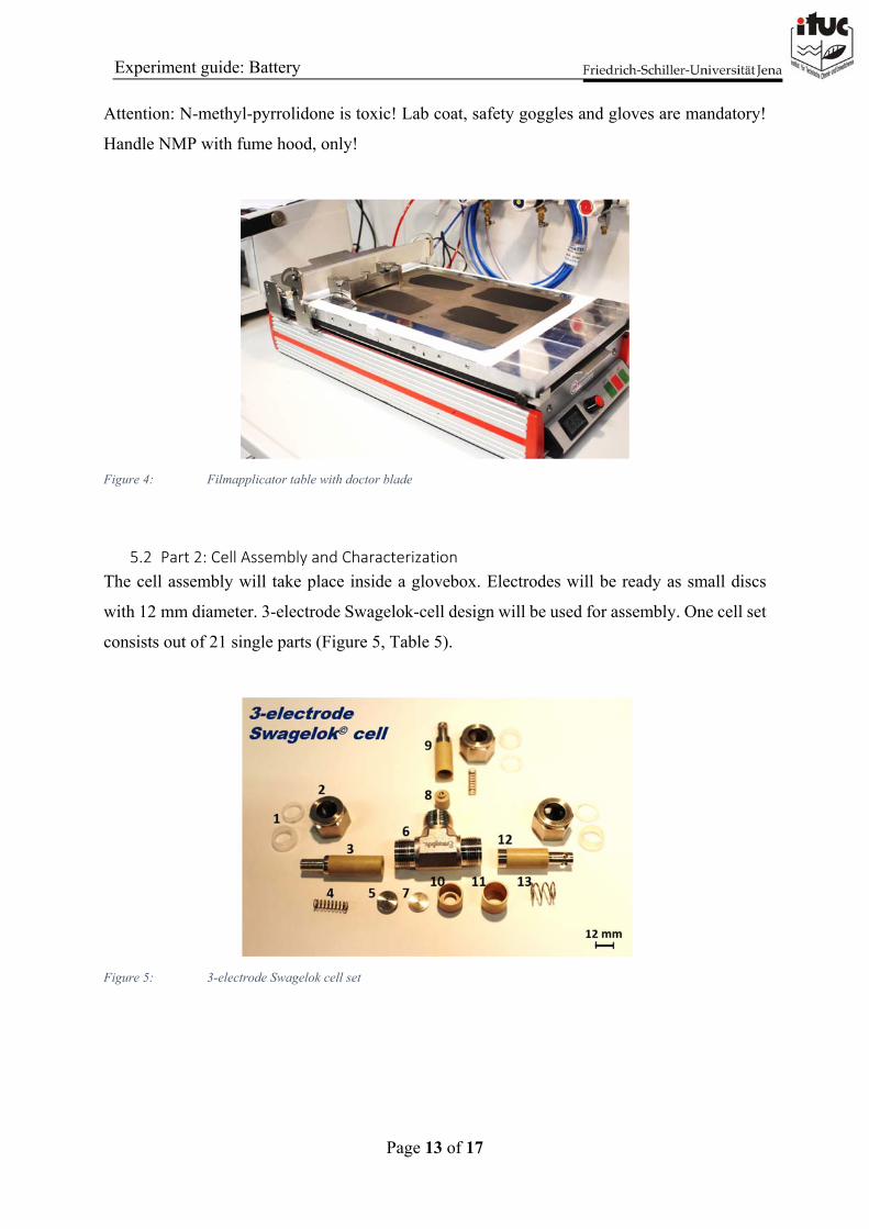
The cell assembly will take place inside a glovebox. Electrodes will be ready as small discs
with 12 mm diameter. 3-electrode Swagelok-cell design will be used for assembly. One cell set
consists out of 21 single parts (Figure 5, Table 5).
Figure 5: 3-electrode Swagelok cell set
Page 14 of 17
Experiment guide: Battery
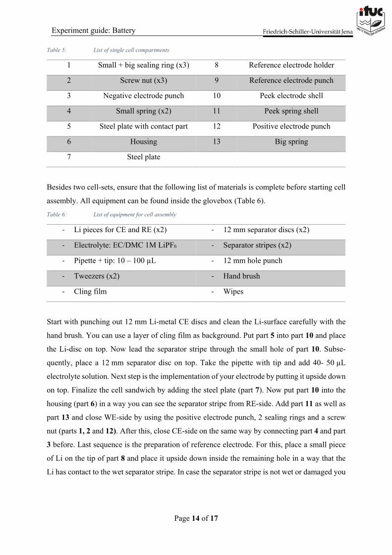
Table 5: List of single cell compartments
1 Small + big sealing ring (x3) 8 Reference electrode holder
2 Screw nut (x3) 9 Reference electrode punch
3 Negative electrode punch 10 Peek electrode shell
4 Small spring (x2) 11 Peek spring shell
5 Steel plate with contact part 12 Positive electrode punch
6 Housing 13 Big spring
7 Steel plate
Besides two cell-sets, ensure that the following list of materials is complete before starting cell
assembly. All equipment can be found inside the glovebox (Table 6).
Table 6: List of equipment for cell assembly
‐ Li pieces for CE and RE (x2) ‐ 12 mm separator discs (x2)
‐ Electrolyte: EC/DMC 1M LiPF6 ‐ Separator stripes (x2)
‐ Pipette + tip: 10 – 100 µL ‐ 12 mm hole punch
‐ Tweezers (x2) ‐ Hand brush
‐ Cling film ‐ Wipes
Start with punching out 12 mm Li-metal CE discs and clean the Li-surface carefully with the
hand brush. You can use a layer of cling film as background. Put part 5 into part 10 and place
the Li-disc on top. Now lead the separator stripe through the small hole of part 10. Subse-
quently, place a 12 mm separator disc on top. Take the pipette with tip and add 40- 50 µL
electrolyte solution. Next step is the implementation of your electrode by putting it upside down
on top. Finalize the cell sandwich by adding the steel plate (part 7). Now put part 10 into the
housing (part 6) in a way you can see the separator stripe from RE-side. Add part 11 as well as
part 13 and close WE-side by using the positive electrode punch, 2 sealing rings and a screw
nut (parts 1, 2 and 12). After this, close CE-side on the same way by connecting part 4 and part
3 before. Last sequence is the preparation of reference electrode. For this, place a small piece
of Li on the tip of part 8 and place it upside down inside the remaining hole in a way that the
Li has contact to the wet separator stripe. In case the separator stripe is not wet or damaged you
Page 15 of 17
Experiment guide: Battery
have to add a further piece of separator and wet it with 10 µL of electrolyte before implemen-
tation of part 8. Finally, close the RE side like you closed the CE side. Cell assembly is com-
pleted!
Galvanostatic cycling will take place at a MPG-2 battery cycler (Biologic) at a current rate of
C/5 e.g. 5 h for each discharge and charge step. For this, connect the WE with red cables, the
CE with blue cables and the RE with the white cable. Potential limits depend on the active
materials inside the working electrode and will be discussed before starting the cell. 5 discharge
and charge cycles are projected.
Figure 6: Central part of Swagelok cell assembly. Numbers correspond to Table 5.
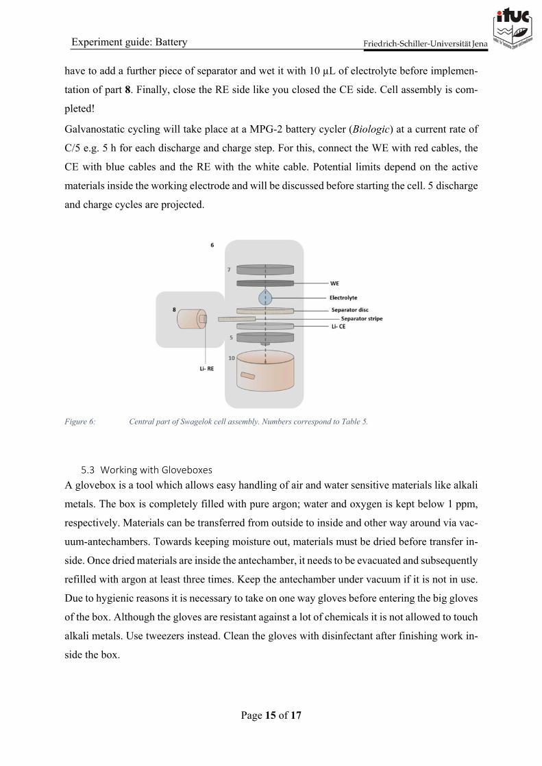
5.3 Working with Gloveboxes
A glovebox is a tool which allows easy handling of air and water sensitive materials like alkali
metals. The box is completely filled with pure argon; water and oxygen is kept below 1 ppm,
respectively. Materials can be transferred from outside to inside and other way around via vac-
uum-antechambers. Towards keeping moisture out, materials must be dried before transfer in-
side. Once dried materials are inside the antechamber, it needs to be evacuated and subsequently
refilled with argon at least three times. Keep the antechamber under vacuum if it is not in use.
Due to hygienic reasons it is necessary to take on one way gloves before entering the big gloves
of the box. Although the gloves are resistant against a lot of chemicals it is not allowed to touch
alkali metals. Use tweezers instead. Clean the gloves with disinfectant after finishing work in-
side the box.
Page 16 of 17
Experiment guide: Battery
Glovebox works require attention and patience, particularly for beginners. Mistakes might lead
to severe disturbance of other experiments. In interest of all users: Do not start working without
supervision of respective lab course assistant!
Figure 7: Glovebox (MBraun)
6. Report and Data Analysis
Several days after experiment you will receive the cycling results of your battery as “.xls”.
Please pay attention in your report for the following tasks:
‐ Calculate the theoretical capacity of your active material and compare with your achieved capacities. Try to give reasons for differences.
‐ Plot 1st, 2nd and last cycle, respectively (E vs. q). Explain the shape of your cycling curves.
‐ Plot discharge- and charge capacity vs. cycle number. Calculate the coulombic effi-ciency ηC for each cycle. Why is ηC so different in first cycle?
‐ Calculate the energy efficiency for last cycle, respectively. Give reasons for your val-ues.

Page 17 of 17
Experiment guide: Battery
7. References
[1] D. D. Sarma, A. K. Shukla; Building Better Batteries- A Travel Back in Time. ACS
Energ. Lett. 3, 2018
[2] Linden’s Handbook of Batteries, fourth edition, Thomas B. Reddy, McGraw Hill, 2011
[3] M. Li, J. Lu, Z. Chen, K. Amine; 30 Years of Li-ion batteries. Adv. Mater. 30 (33), 2018
[4] A. Thielmann, A. Sauer, M. Wietschel; Gesamt Roadmap Energiespeicher für die Elekt-
romobilität 2030, Fraunhofer ISI Karlsruhe, 2015
[5] S. Chou, Y. Yu; Next Generation Batteries: Aim for the Future. Adv. Energ. Mater. 7
(24), 2017