15LE_e4.fm - My Committeesmycommittees.api.org/standards/ecs/sc15/Committee D… · Web viewTees,...
57
Specification for Cross Linked Polyethylene Line Pipe (PEX) Upstream Segment API SPECIFICATION 15PX DRAFT 1, APRIL 2017
Transcript of 15LE_e4.fm - My Committeesmycommittees.api.org/standards/ecs/sc15/Committee D… · Web viewTees,...
Specification for Cross Linked Polyethylene Line Pipe (PEX)
Upstream Segment
API SPECIFICATION 15PX DRAFT 1, APRIL 2017
Special Notes
API publications necessarily address problems of a general nature. With respect to particular circumstances, local, state, and federal laws and regulations should be reviewed.
Neither API nor any of API's employees, subcontractors, consultants, committees, or other assignees make any warranty or representation, either express or implied, with respect to the accuracy, completeness, or usefulness of the information contained herein, or assume any liability or responsibility for any use, or the results of such use, of any information or process disclosed in this publication. Neither API nor any of API's employees, subcontractors, consultants, or other assignees represent that use of this publication would not infringe upon privately owned rights.
API publications may be used by anyone desiring to do so. Every effort has been made by the Institute to assure the accuracy and reliability of the data contained in them; however, the Institute makes no representation, warranty, or guarantee in connection with this publication and hereby expressly disclaims any liability or responsibility for loss or damage resulting from its use or for the violation of any authorities having jurisdiction with which this publication may conflict.
API publications are published to facilitate the broad availability of proven, sound engineering and operating practices. These publications are not intended to obviate the need for applying sound engineering judgment regarding when and where these publications should be utilized. The formulation and publication of API publications is not intended in any way to inhibit anyone from using any other practices.
Any manufacturer marking equipment or materials in conformance with the marking requirements of an API standard is solely responsible for complying with all the applicable requirements of that standard. API does not represent, warrant, or guarantee that such products do in fact conform to the applicable API standard.
All rights reserved. No part of this work may be reproduced, stored in a retrieval system, or transmitted by any means, electronic, mechanical, photocopying, recording, or otherwise, without prior written permission from the publisher. Contact the
Publisher, API Publishing Services, 1220 L Street, N.W., Washington, D.C. 20005.
Copyright © 2008 American Petroleum Institute
Foreword
Nothing contained in any API publication is to be construed as granting any right, by implication or otherwise, for the manufacture, sale, or use of any method, apparatus, or product covered by letters patent. Neither should anything contained in the publication be construed as insuring anyone against liability for infringement of letters patent.
This document was produced under API standardization procedures that ensure appropriate notification and participation in the developmental process and is designated as an API standard. Questions concerning the interpretation of the content of this publication or comments and questions concerning the procedures under which this publication was developed should be directed in writing to the Director of Standards, American Petroleum Institute, 1220 L Street, N.W., Washington, D.C. 20005. Requests for permission to reproduce or translate all or any part of the material published herein should also be addressed to the director.
Generally, API standards are reviewed and revised, reaffirmed, or withdrawn at least every five years. A one-time extension of up to two years may be added to this review cycle. Status of the publication can be ascertained from the API Standards Department, telephone (202) 682-8000. A catalog of API publications and materials is published annually and updated quarterly by API, 1220 L Street, N.W., Washington, D.C. 20005.
Suggested revisions are invited and should be submitted to the Standards Department, API, 1220 L Street, NW, Washington, D.C. 20005, [email protected].
This standard shall become effective on the date printed on the cover but may be used voluntarily from the date of distribution.
Contents
Page
1 Scope.............................................................................................................................................................. 11.1 Purpose........................................................................................................................................................... 11.2 Applications.................................................................................................................................................... 11.3 Unit Conversion.............................................................................................................................................. 1
2 References...................................................................................................................................................... 22.1 General............................................................................................................................................................ 22.2 Requirements.................................................................................................................................................. 32.3 Equivalent Standards..................................................................................................................................... 3
3 Glossary (Definitions, Abbreviations)...........................................................................................................43.1 Definitions....................................................................................................................................................... 43.2 Abbreviations.................................................................................................................................................. 6
4 Purchasing Guidelines................................................................................................................................... 64.1 General............................................................................................................................................................ 6
5 Design............................................................................................................................................................. 75.1 Design............................................................................................................................................................. 75.2 Dimensions and Tolerances........................................................................................................................ 10
6 Process of Manufacture............................................................................................................................... 106.1 Process of Manufacture............................................................................................................................... 106.2 Materials........................................................................................................................................................ 156.3 Rework Material............................................................................................................................................ 156.4 Fittings........................................................................................................................................................... 156.5 Finish and Workmanship............................................................................................................................. 16
7 Quality Program........................................................................................................................................... 167.1 Quality Manual.............................................................................................................................................. 167.2 Quality Control Tests................................................................................................................................... 177.3 Inspection and Rejection............................................................................................................................. 20
8 Equipment Marking...................................................................................................................................... 208.1 General.......................................................................................................................................................... 20
9 Handling, Storage and Installation..............................................................................................................219.1 Storage.......................................................................................................................................................... 219.2 Handling........................................................................................................................................................ 219.3 Installation..................................................................................................................................................... 22
Annex A (informative) Conversions......................................................................................................................23
Annex B (informative) External Pressure Rating (Collapse Pressure)..............................................................25
Annex C (informative) Cross-linked Polyethylene...............................................................................................27
Annex D (informative) API Monogram..................................................................................................................29
Annex E (informative) Installation.........................................................................................................................31
Specification for Cross Linked Polyethylene Line Pipe (PEX)
1 Scope1.1 Purpose
The purpose of this specification is to provide standards for cross linked polyethylene (PEX) line pipe suitable for use in conveying oil, gas and non-potable water in underground, above ground and reliner applications for the oil and gas producing industries.
The standard does not propose to address all of the safety concerns associated with the design, installation or use of products suggested herein. It is the responsibility of the user of the standard to utilize appropriate health and safety considerations.
All pipe produced under this standard must utilize pressure rated materials, but may be used in pressurized, non- pressure and negative pressure applications.
The technical content of this document provides requirements and guidelines for performance, design, materials inspection, dimensions and tolerances, marking, handling, storing and shipping.
1.2 Applications
1.2.1 Equipment
This specification covers PEX line pipe utilized for the production and transportation of oil, gas and non-potable water. The piping is intended for use in new construction, structural, pressure-rated liner, line extension and repair, of both above ground and buried pipe applications. Specific equipment covered by this specification is listed as follows:
1) PEX line pipe;
2) Fittings.
1.2.2 Service Conditions
The standard service conditions for the API Spec15PX Standard Pressure Rating are as follows:
1) HDB or MRS/CRS is established to 50 years;2) Service temperature range: -50° C (-58 °F) to 95° C (203 °F)
Note – applications above 95° C (203 °F) require special design consideration.
3) The fluid environment is oil, gas and non-potable water.4) Axial loads shall include end loads due to pressure only.5) Service conditions other than the standard API Spec 15PX conditions are discussed in Section 5—Design.
2 References2.1 GeneralThis specification includes by reference, either in total or in part, the most current issue of the following standards:
ANSI B16.5, Pipe Flanges and Flanged Fittings
ASTM D638, Standard Test Method for Tensile Properties of Plastics
ASTM D792, Standard Test Methods for Density and Specific Gravity (Relative Density) of Plastics by Displacement
ASTM D1238, Standard Test Method for Melt Flow Rates of Thermoplastics by Extrusion Plastometer
ASTM D1505, Standard Test Method for Density of Plastics by the Density-Gradient Technique
ASTM D1598, Standard Test Method for Time-to Failure of Plastic Pipe Under Constant Internal Pressure
ASTM D1599, Standard Test Method for Resistance to Short-Time Hydraulic Failure Pressure of Plastic Pipe, Tubing and Fittings
ASTM D1600, Standard Terminology for Abbreviated Terms Relating to Plastics
ASTM D2122, Standard Test Method for Determining Dimensions of the Thermoplastic Pipe and Fittings
ASTM D2290, Standard Test Method for Apparent Hoop Tensile Strength of Plastic or Reinforced Plastic by Split Disk Method
ASTM D2513, Standard Specification for Thermoplastic Gas Pressure Pipe, Tubing and Fittings
ISO 14531 – 1 - Plastics pipes and fittings — Crosslinked polyethylene (PE-X) pipe systems for the conveyance of gaseous fuels — Metric series – Pipes
ISO 14531 – 2 - Plastics pipes and fittings — Crosslinked polyethylene (PE-X) pipe systems for the conveyance of gaseous fuels — Metric series - Pipes
ISO 14531 – 3 - Plastics pipes and fittings — Crosslinked polyethylene (PE-X) pipe systems for the conveyance of gaseous fuels — Metric series - Pipes
ISO 14531 – 4 - Plastics pipes and fittings — Crosslinked polyethylene (PE-X) pipe systems for the conveyance of gaseous fuels — Metric series - Pipes
ASTM D2765, Standard Test Methods for Determination of Gel Content and Swell Ratio of Crosslinked Ethylene Plastics
ISO 10147, Pipes and fittings made of crosslinked polyethylene (PE-X) — Estimation of the degree of crosslinking by determination of the gel content
ISO 1167, Thermoplastics pipes, fittings and assemblies for the conveyance of fluids — Determination of the resistance to internal pressure
ISO 2505, Thermoplastics pipes – longitudinal reversion – test method and parameters.
EN 728, Plastics piping and ducting systems. Polyolefin pipes and fittings. Determination of oxidation induction time
ASTM D2774, Standard Practice for Underground Installation of Thermoplastic Pressure Piping
ASTM D2837, Standard Test Method for Obtaining Hydrostatic Design Basis for Thermoplastic Pipe Materials
ISO 9080, Plastics piping and ducting systems -- Determination of the long-term hydrostatic strength of thermoplastics materials in pipe form by extrapolation
ISO 12162, Thermoplastics materials for pipes and fittings for pressure applications -- Classification, designation and design coefficient
ASTM F2905, Black Crosslinked Polyethylene (PEX) Line Pipe, Fittingsand Joints for Oil and Gas Producing Applications
ASTM F2968, Standard Specification for Black Crosslinked Polyethylene (PEX) Pipe, Fittings and Joints for Gas Distribution Applications
ASTM F2788, Standard Specification for Metric and Inch-sized Crosslinked Polyethylene (PEX) Pipe
ASTM – 2829, Standard Specification for Metric-Sized Crosslinked Polyethylene (PEX) Pipe Systems
ASTM F412, Standard Terminology Relating to Plastic Piping Systems
ASTM F1055, Standard Specification for Electrofusion Type Polyethylene Fittings for Outside Diameter Controlled Polyethylene Pipe and Tubing
DIN 16892/3, Crosslinked high-density polyethylene (PE-X) pipes
ISO 4065, Thermoplastics pipes — Universal wall thickness table
ISO 11922, Thermoplastics pipes for the conveyance of fluids — Dimensions and tolerances —Part 1: Metric series
ISO 161-1, Thermoplastics pipes for the conveyance of fluids — Nominal outside diameters and nominal pressures - Part 1: Metric series
ASTM F2206, Standard Specification for Fabricated Fittings of Butt-Fused Polyethylene (PE) Plastic Pipe, Fittings, Sheet Stock, Plate Stock or Block Stock
ISO 4427-3, Plastics piping systems — Polyethylene (PE) pipes and fittings for water supply - Part 3: Fittings
PPI TN-7, Nature of Hydrostatic Stress Rupture Curves
PPI TR-3, Policies and Procedures for Developing Hydrostatic Design Basis (HDB), Pressure Design Basis (PDB), Strength Design Basis (SDB) and Minimum Required Strength (MRS) Ratings for Thermoplastic Pipe Materials or Pipe
PPI TR-4, Listing of Hydrostatic Design Basis (HDB), Strength Design Basis (SDB), Pressure Design Basis (PDB), and Minimum Required Strength (MRS) Ratings for Thermoplastic Piping Materials or Pipe
PPI TR-9, Recommended Design Factors for Pressure Applications of Thermoplastic Pressure Pipe Materials
PPI TR-41, Generic Saddle Fusion Joining Procedure for Polyethylene Gas Piping
U.S. DOT Title 49, CFR Part 192, Transportation of Natural and Other Gas by Pipeline: Minimum Federal Safety Standards
2.2 Requirements
Requirements of other standards included by reference in this specification are essential to the safety and interchangeability of the equipment produced.
2.3 Equivalent Standards
Standards referenced in this specification may be replaced by other international or national standards that can be shown to meet or exceed the requirements of the referenced standard. Manufacturers who use other standards in lieu of standards referenced herein are responsible for documenting the equivalency of the standards. Where a standard is revised, the latest edition may be used on issue and shall become mandatory 6 months from the date of the revision.
3 Glossary (Definitions, Abbreviations)3.1 Definitions
3.1.1acceptance criteriaDefined limits placed on characteristics of materials, products, or services.
3.1.2adaptersAppurtenances that allow connecting components with different joining systems.
3.1.3pressure rating (PR) the estimated maximum water pressure the pipe is capable of withstanding continuously with a high degree of certainty that failure of the pipe will not occur.
3.1.4componentAny pressure line pipe, pipe connection, fitting, flange, adapter, reducer, or end of outlet connection covered by this specification.
3.1.5Design Service Factor (DSF)A safety factor applied to the Hydrostatic Design Basis (HDB) to calculate the hydrostatic design stress.
3.1.6 overall service (design) coefficientOverall coefficient, with a value greater than 1, that takes into consideration service conditions as well as propertiesof the components of a piping system other than those represented in σLPL
NOTE: See annex E and ISO 12162 for information regarding the minimum permissible service (design) coefficient for PE-X pipes.
3.1.7eccentricityThe wall thickness variability as measured and calculated in accordance with ASTM D2122 Test Method in any diametrical cross section of the pipe shall be within 12 %. Wall thickness eccentricity range shall be measured in accordance with ASTM D2513, Section 6.5.1.3.
3.1.9fittingsTees, 90s elbows, 45s elbows and fittings manufactured by butt fusion welding of shape modified or mitered components prepared from molded fittings, sheet stock or block made of Polyethylene or PEX..Electro fusion fittings according to ISO 8083, ASTM F1055 and ISO 14531 part 2.Mechanical metallic fittings according to ISO 14531 part 3.
3.1.10flangesFace flanges with bolt hole circle per ANSI B16.5. Flanges and flange adapter as used in this specification, incorporates use of polyethylene flange adapter and metallic backup ring utilizing ANSI B16.5 bolt hole pattern.Metallic Flange couplers for field installations are also covered by this specificationPEX face flanges used as internal diameter adapters are also covered by this specification
3.1.11Fluid Service Factor (FSF)Factor applied to the Hydrostatic Design Stress (HDS) or the MRS/CRS method to account for the impact of the
transported fluid on pipe performance.
3.1.11Hydrostatic Design Basis (HDB)The categorized Long-term Hydrostatic Strength (LTHS) in the circumferential or hoop direction for a given set of end use conditions, as established by ASTM D2837, Standard Test Method for Obtaining Hydrostatic Design Basis for Thermoplastic Pipe Materials.
3.1.12Hydrostatic Design Stress (HDS)The maximum allowable working hoop stress in the pipe wall when the pipe is subjected to long term hydrostatic pressure. The HDS at 73.4 °F is determined by reducing the HDB at 73.4 °F by a Design Service Factor (DSF), a multiplier of less than 1.0.
3.1.13 MRS (minimum required strength)The Minimum Required Strength (MRS) is the categorized lower prediction limit (LPL) of the long-term hydrostatic strength at 20°C determined in accordance with ISO 9080 and ISO 12162.
CRS (Categorized Required Strength)The Categorized Required Strength, CRS θ,t, is the categorized lower prediction limit (LPL) of the long-term hydrostatic strength at a temperature (θ) and a time (t) as determined in accordance with ISO 9080 and ISO 12162. CRS θ,t , at 20°C and 50 years equals MRS.
design stress (σS)—stress equal to the Minimum Required Strength (MRS) or Categorized Required Strength (CRS) divided by the design coefficient (C) for water.
σS = MRS / C or CRS / C (1)σS = MRS / 1.25 (for this standard)
3.1.13lot numberAssignment of a unique code to each lot of manufactured pipe or fittings under the same conditions of production. Lot numbers are used to maintain production identification and traceability.
3.1.14ovalityThe maximum measured diameter, minus the minimum measured diameter, divided by the average measured diameter, times 100, expressed as a percentage:
Ovality (%)=(max . measured diameter−min .measured diameter)(average measured diameter)
× 100
3.1.15Material designation code
A set of letters and numbers used to identify stress-rated thermoplastic compounds. The code consists of two or three letters which describe the type of material i.e. PE, PVC, PB, PEX, etc., per ASTM D1600. This is followed by four numbers to describe material and physical properties in accordance with PPI TR-4.
3.1.16reducersComponent fittings that allow two pipes of different diameters to be connected.
3.1.17shallIn this document, the word “shall” is used to indicate requirements, which are mandatory.
3.1.20Standard Dimension Ratio (SDR) or Dimension Ratio (DR)Interchangeably used terms equal to the ratio of a pipe’s outside diameter to its wall thickness.
3.1.21Standard Pressure Rating (PR)The established maximum pressure that a fluid in the pipe can exert continuously with a high degree of certainty that failure in the pipe will not occur.
3.1.22Temperature Service Factor (TSF)Factor applied to the HDS to compensate for the circumstance where elevated temperature HDB data is not available.3.1.23visual examinationExamination of parts and equipment for visible defects in material and workmanship.
3.1.24working pressureThe maximum anticipated, sustained operating pressure applied to the pipe in actual service. – what is the difference between this para. and para.3.1.21?
3.2 Abbreviations
ANSI American National Standards
Institute API American Petroleum Institute
ASTM American Society of Testing and
Materials DSF Design Service Factor
DR Dimension Ratio
HDB Hydrostatic Design Basis
HDS Hydrostatic Design Stress
LTHS Long-term Hydrostatic
Strength PPI Plastics Pipe Institute, Inc.
ISO International Organization for Standardization
DIN Deutsch Institute for Norms
MRS Minimum required stress
CRS Categorized Required Strength
4 Design4.1 Long Term Hydrostatic Strength (LTHS)Either the HDB or ISO 9080 long term strength shall be used to establish the maximum operating pressure of a PEX piping system. The design process shall include consideration of uncertainties in manufacture, transportation and installation, which comprises the Design Factor; and the chemical environment which is included in the Fluid Service Factor (FSF).
4.2 Calculating the Maximum Operating Pressure
4.2.1 To use the HDB
1) Select the appropriate HDB based on the anticipated operating temperature2) Values for maximum operating pressure in water service are listed in Table 1. 3) An appropriate Fluid Service Factor shall be used from Table 3. To calculate the Maximum Operating
Pressure, multiply the appropriate pressure from Table 1 by the appropriate FSF from Table 3. 4) If the selected PEX grade also has an ISO 9080 rating from an ISO 17025 certified laboratory the pressure
values in Table 1 may be multiplied by 1.14 to calculate a higher maximum operating pressure.5) When calculating a HDB between 23° C (73.4 °F) and the elevated temperature at which the manufacturer
has an established HDB, the HDB at any intermediate temperature may be calculated by linear interpolation using the method described in PPI TR-3.
Table 1: Maximum Operating Pressure (psi) of PEX pipe at various temperatures with no fluid service factor applied. The design factor is 0.7.
Temperature°C (°F)
Material Designation
Code
HDB (psi)
Maximum Operating Pressure, psig for the Indicated SDR
SDR 7.4 SDR 9 SDR 11 SDR 13.6 SDR 17
23 (73)PEX xxx6 1250 273 219 175 139 109PEX xxx8PEX xxx8 1600 350 280 224 178 140
60 (140)PEX xxx6 8001 208 166 133 105 83PEX xxx8 10001 233 186 149 118 93
82 (180) PEX xxx6PEX xxx8 800 175 140 112 89 70
93 (200) PEX xxx6PEX xxx8 630 138 110 88 70 55
1 HDB was interpolated using the HDB values at 23° C and 82° C for the grades with the indicated Material Designation Code.
4.2.2 To use the ISO 9080 Pressure Rating
1) Use Table 2 to determine the maximum operating pressure for pipe rated using the ISO 9080 method.
2) An appropriate Fluid Service Factor shall be used from Table 3. To calculate the Maximum Operating Pressure, multiply the appropriate pressure from Table 2 by the appropriate FSF from Table 3.
Table 1: Maximum working pressure (psig) for PEX pipes rated using ISO 9080, with a service factor of 1.25 for 20-year service life except for 90° C (15 years life) and 95° C (10 years life.)
Temperature°C (°F)
Maximum Operating Pressure (psig) for the indicated SDRSDR 7.4 SDR 9 SDR 11 SDR 13.6
10 (50) 396 315 249 19920 (68) 351 278 220 17530 (86) 310 247 196 15540 (104) 277 219 174 13850 (122) 247 196 155 12360 (140) 220 174 138 11070 (158) 197 157 123 9980 (176) 175 139 110 8890 (194) 160 126 100 8095 (203) 152 120 96 75
4.2.3 The Fluid Service Factors in Table 3 shall be used to account for possible chemical effects of the transported medium on the long-term performance of the piping and hazardous nature of the application.
Table 2: Fluid Service Factors (FSF)
Environment Factor
Produced water, seawater, brine, process water and other oilfield water based fluids excluding oilfield water containing > 2 % liquid hydrocarbons1
1.0
Dry gas gathering (no associated hydrocarbon liquids)2 1.0
Dry gas gathering that is subject to Canadian Federal Regulations3 1.0
Multiphase fluids, wet natural gas and liquid hydrocarbons 0.5 1Water containing significant quantities of liquid hydrocarbons (> 2%) shall be treated as hydrocarbon liquids in
this instance. 2Gas gathering in this standard refers to gas from a well or production source in a low population density area that
is not subject to Department of Transportation, Office of Pipeline Safety, Title 49 CFR Part 192. 3CSA Z662 Clause 13.3.
4.2.4 External Collapse Rating
Guidelines on the collapse rating of polyethylene pipe are laid out in Annex B.
5.2 Dimensions and Tolerances
5.2.1 Size
Pipe furnished to this specification shall comply with the dimensions and tolerances given in Table 5 or Table 6 as specified on the purchase order.
In applications where special conditions or requirements dictate diameters, wall thicknesses or dimensions other than those listed in this table, if the PEX pipe is manufactured from PEX compounds meeting the requirements of this specification and the strength and design basis is the same, meeting all the requirements of this specification it shall be acceptable.For diameters not shown in the table, the tolerance shall be the same percentage as that used in the table for the next smaller listed size.
5.2.2 Toe-in
The outside diameter when measured at the cut end of the pipe length shall not be more than 1.5 % smaller than the outside diameter specified in Table 5 or Table 6, when measured at any point within 1.5 pipe diameters or 11.8 in. (300 mm), whichever is less, to the cut end of the pipe length. Measurements shall be made using ASTM D2122 Test Method.
5.2.3 Eccentricity
The wall thickness variability as measured and calculated in accordance with ASTM D2122 Test Method in any diametrical cross section of the pipe should not exceed 12 % unless otherwise specified elsewhere in this standard.
5.2.4 Length
Pipe shall be furnished in cut lengths or coils as specified on the purchase order. Two pieces electro-fused together to make a length are acceptable. Measurements shall be made using ASTM D2122 Test Method.
5.2.5 Ovality
The ovality of the pipe shall not exceed the tolerance in ASTM F2788. Other factors such as installation, compaction, static soil loading, exposure to high ambient temperature and vehicular loads may increase ovality.
6 Process of ManufacturePipe furnished to this specification shall be produced by extrusion.
Fittings shall be manufactured using polymers, metals, or composites and shall comply with the relevant product standards for that fitting type.
PEX pipes must be cross linked at least to the minimum level specified in this standard when leaving the production facility. Curing in the field and/or after installation is not permitted.
6.1 Materials6.1.1 Basic Materials 6.1.1.1 PEX pipe shall be made from polyethylene compounds which have been crosslinked by means such that
the pipe meets the performance requirements of Section 6. For the use temperatures that the pipe will be marked for, the materials, procedure for mixing, and the process for crosslinking shall result in a product with pressure ratings as shown in Section 4.2, when determined in accordance with procedures no less restrictive than those of ISO 9080, ASTM D2837 or PPI TR-3.
6.1.1.2 The HDB or MRS/CRS shall be established by the manufacturer in accordance with PPI TR-3 using ASTM D2837 or ISO 9080 methodology. PEX materials meeting the requirements of this specification shall be tested for long term hydrostatic strength witnessed or tested by a certified third party or, have an HDB and/or MRS listed in PPI TR-4.
6.1.2 Color: If the color of the pipe is black, the formulation shall contain carbon black as a colorant, and the formulation shall meet the requirements of 6.2.3.
6.1.3 UV Protection: The pipe shall be protected against UV radiation and shall be marked with the maximum UV exposure time in years, based on the manufacturer’s testing of UV exposed pipe in accordance with Test Method F2657 or ISO 14531-1 Annex C. Longer periods and/or above ground installation are permissible based on the agreement between the customer and the manufacturer.
6.2 Rework/recycled MaterialRework or recycled material is not permitted.
6.3 FittingsFittings furnished for use with this specification shall meet requirements of specification ASTM F1055 or ISO 8083 for electrofusion fittings, ASTM F2206 or ISO 4427 part 3 for fabricated fittings and ASTM D2683 for socket fused fittings.
6.4 Finish and Workmanship
6.4.1 Pipe EndsPipe ends shall be plain and squared.Pipe ends may also be supplied with a flared end – conditions shall be agreed between purchaser and the seller.
6.4.2 FinishThe interior and exterior of the pipe shall be uniform in finish without voids, cracks, crazing, foreign inclusions or deep scratches.
6.4.3 WorkmanshipCut pipe ends shall be clean without ledges, shaving tails, burrs or cracks.The interior of the pipe shall be blown or washed clean of cuttings and shavings.
.
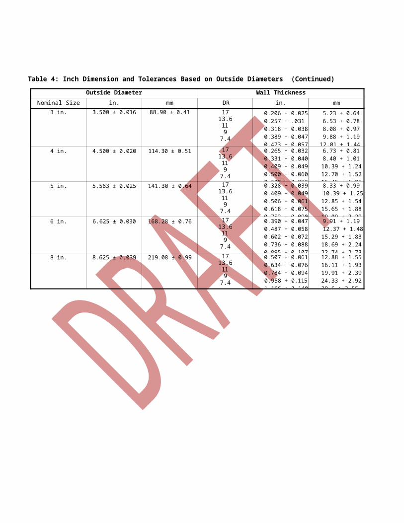
11Table 4: Inch Dimensions and Tolerances Based on Outside Diameters
Outside Diameter Wall ThicknessNominal Size (in.) in. mm DR in. mm
1/2 0.840 ± 0.004 21.34 ± 0.10 1713.6119
7.4
0.049 + 0.0060.062 + 0.0070.076 + 0.0090.093 + 0.0110.110 + 0.014
1.26 + 0.151.57 + 0.191.94 + 0.232.37 + 0.282.88 + 0.35
3/4 1.050 ± 0.004 26.67 ± 0.10 1713.6119
7.4
0.062 + 0.0070.077 + 0.0090.095 + 0.0110.117 + 0.0140.142 + 0.017
1.57 + 0.191.96 + 0.242.42 + 0.292.96 + 0.363.60 + 0.43
1 1.315 ± 0.005 33.40 ± 0.13 1713.6119
7.4
0.077 + 0.0090.097 + 0.0120.120 + 0.0140.146 + 0.0180.178 + 0.021
1.96 + 0.242.46 + 0.293.04 + 0.363.71 + 0.454.57 + 0.54
1 1/4 in. 1.660 ± 0.005 42.16 ± 0.13 1713.6119
7.4
0.098 + 0.0120.122 + 0.0150.151 + 0.0180.184 + 0.0220.224 + 0.027
2.48 + 0.303.10 + 0.373.83 + 0.464.67 + 0.565.70 + 0.68
1 1/2 in. 1.900 ± 0.006 48.26 ± 0.15 1713.6119
7.4
0.112 + 0.0130.140 + 0.0170.173 + 0.0210.211 + 0.0250.257 + 0.031
2.84 + 0.343.55 + 0.434.39 + 0.535.36 + 0.646.52 + 0.78
2 in. 2.375 ± 0.006 60.33 ± 0.15 1713.6119
7.4
0.140 + 0.0170.175 + 0.0210.216 + 0.0260.264 + 0.0320.321 + 0.039
3.55 + 0.434.44 + 0.535.48 + 0.666.70 + 0.808.15 + 0.99
2 1/2 in. 2.875 ± 0.007 73.0 ± 0.18 1713.6119
7.4
0.169 + 0.0200.211 + 0.0250.261 + 0.0310.319 + 0.0380.389 + 0.047
4.30 + 0.525.37 + 0.646.64 + 0.808.11 + 0.97
9.87 + 1.18

Table 4: Inch Dimension and Tolerances Based on Outside Diameters (Continued)
Outside Diameter Wall ThicknessNominal Size (in.) in. mm DR in. mm
3 in. 3.500 ± 0.016 88.90 ± 0.41 1713.6119
7.4
0.206 + 0.0250.257 + .0310.318 + 0.0380.389 + 0.0470.473 + 0.057
5.23 + 0.646.53 + 0.788.08 + 0.979.88 + 1.19
12.01 + 1.44
4 in. 4.500 ± 0.020 114.30 ± 0.51 1713.6119
7.4
0.265 + 0.0320.331 + 0.0400.409 + 0.0490.500 + 0.0600.608 + 0.073
6.73 + 0.818.40 + 1.0110.39 + 1.2412.70 + 1.5215.45 + 1.85
5 in. 5.563 ± 0.025 141.30 ± 0.64 1713.6119
7.4
0.328 + 0.0390.409 + 0.0490.506 + 0.0610.618 + 0.0750.752 + 0.090
8.33 + 0.9910.39 + 1.2512.85 + 1.5415.65 + 1.8819.09 + 2.29
6 in. 6.625 ± 0.030 168.28 ± 0.76 1713.6119
7.4
0.390 + 0.0470.487 + 0.0580.602 + 0.0720.736 + 0.0880.895 + 0.107
9.91 + 1.1912.37 + 1.4815.29 + 1.8318.69 + 2.2422.74 + 2.73
8 in. 8.625 ± 0.039 219.08 ± 0.99 1713.6119
7.4
0.507 + 0.0610.634 + 0.0760.784 + 0.0940.958 + 0.1151.166 + 0.140
12.88 + 1.5516.11 + 1.9319.91 + 2.3924.33 + 2.9229.6 + 3.55
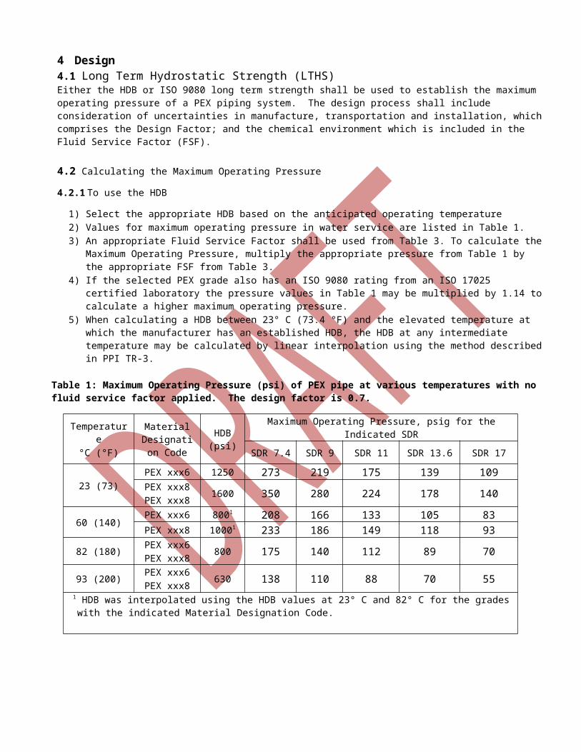
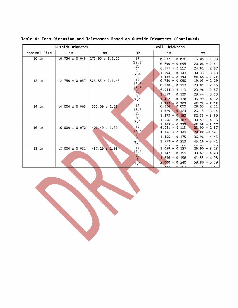
Table 4: Inch Dimension and Tolerances Based on Outside Diameters (Continued)
Outside Diameter Wall ThicknessNominal Size (in.) in. mm DR in. mm
10 in. 10.750 ± 0.048 273.05 ± 0.1.22 1713.6119
7.4
0.632 + 0.0760.790 + 0.0950.977 + 0.1171.194 + 0.1431.453 + 0.174
16.05 + 1.9320.08 + 2.4124.82 + 2.9730.33 + 3.6336.90 + 4.43
12 in. 12.750 ± 0.057 323.85 ± 0.1.45 1713.613.5119
7.4
0.750 + 0.0900.938 _ 0.1130.944 + 0.1131.159 + 0.1391.417 + 0.1701.723 + 0.207
19.05 + 2.2923.81 + 2.8623.98 + 2.8729.44 + 3.5335.99 + 4.3243.76 + 5.25
14 in. 14.000 ± 0.063 355.60 ± 1.60 1713.6119
7.4
0.824 + 0.0991.029 + 0.1241.273 + 0.1531.556 + 0.1871.892 + 0.227
20.93 + 2.5126.15 + 3.1432.33 + 3.8939.52 + 4.7548.05 + 5.77
16 in. 16.000 ± 0.072 406.40 ± 1.83 1713.6119
7.4
0.941 + 0.1131.176 + 0.1411.455 + 0.1751.778 + 0.2132.162 + 0.259
23.90 + 2.8729.88 +3.5936.96 + 4.4545.16 + 5.4154.92 + 6.59
18 in. 18.000 ± 0.081 457.20 ± 2.05 1713.6119
7.4
1.059 + 0.1271.342 + 0.1591.636 + 0.1962.000 + 0.2402.434 + 0.292
26.90 + 3.2333.62 + 4.0341.55 + 4.9850.80 + 6.1061.78 + 7.41
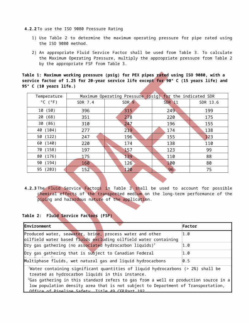
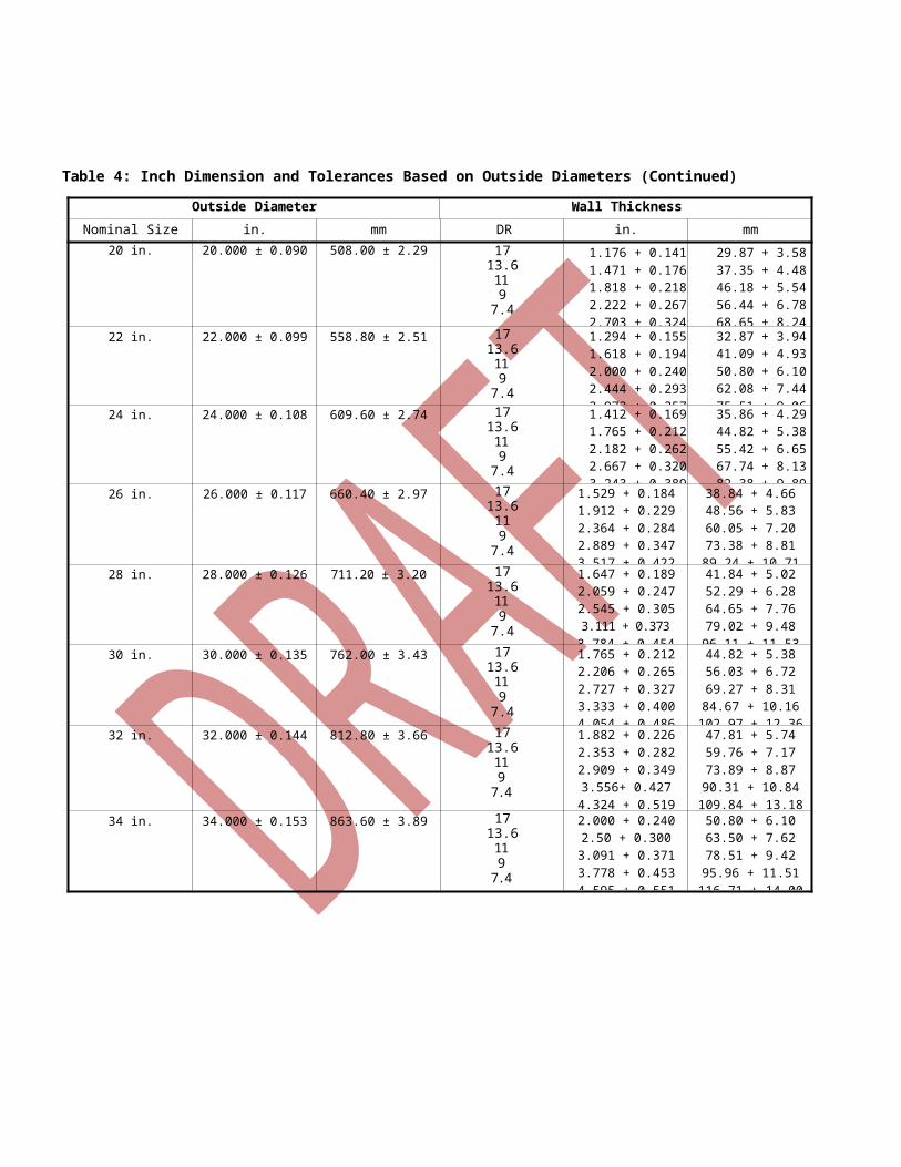
Table 4: Inch Dimension and Tolerances Based on Outside Diameters (Continued)
Outside Diameter Wall ThicknessNominal Size (in.) in. mm DR in. mm
20 in. 20.000 ± 0.090 508.00 ± 2.29 1713.6119
7.4
1.176 + 0.1411.471 + 0.1761.818 + 0.2182.222 + 0.2672.703 + 0.324
29.87 + 3.5837.35 + 4.4846.18 + 5.5456.44 + 6.7868.65 + 8.24
22 in. 22.000 ± 0.099 558.80 ± 2.51 1713.6119
7.4
1.294 + 0.1551.618 + 0.1942.000 + 0.2402.444 + 0.2932.973 + 0.357
32.87 + 3.9441.09 + 4.9350.80 + 6.1062.08 + 7.4475.51 + 9.06
24 in. 24.000 ± 0.108 609.60 ± 2.74 1713.6119
7.4
1.412 + 0.1691.765 + 0.2122.182 + 0.2622.667 + 0.3203.243 + 0.389
35.86 + 4.2944.82 + 5.3855.42 + 6.6567.74 + 8.1382.38 + 9.89
26 in. 26.000 ± 0.117 660.40 ± 2.97 1713.6119
7.4
1.529 + 0.1841.912 + 0.2292.364 + 0.2842.889 + 0.3473.517 + 0.422
38.84 + 4.6648.56 + 5.8360.05 + 7.2073.38 + 8.81
89.24 + 10.71
28 in. 28.000 ± 0.126 711.20 ± 3.20 1713.6119
7.4
1.647 + 0.1892.059 + 0.2472.545 + 0.3053.111 + 0.373
3.784 + 0.454
41.84 + 5.0252.29 + 6.2864.65 + 7.7679.02 + 9.48
96.11 + 11.53
30 in. 30.000 ± 0.135 762.00 ± 3.43 1713.6119
7.4
1.765 + 0.2122.206 + 0.2652.727 + 0.3273.333 + 0.4004.054 + 0.486
44.82 + 5.3856.03 + 6.7269.27 + 8.31
84.67 + 10.16102.97 + 12.36
32 in. 32.000 ± 0.144 812.80 ± 3.66 1713.6119
7.4
1.882 + 0.2262.353 + 0.2822.909 + 0.3493.556+ 0.4274.324 + 0.519
47.81 + 5.7459.76 + 7.1773.89 + 8.87
90.31 + 10.84109.84 + 13.18
34 in. 34.000 ± 0.153 863.60 ± 3.89 1713.6119
7.4
2.000 + 0.2402.50 + 0.300
3.091 + 0.3713.778 + 0.4534.595 + 0.551
50.80 + 6.1063.50 + 7.6278.51 + 9.42
95.96 + 11.51116.71 + 14.00
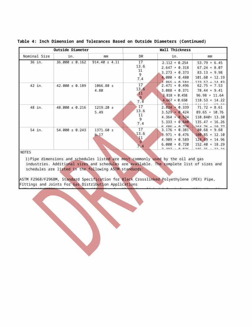
Table 4: Inch Dimension and Tolerances Based on Outside Diameters (Continued)
Outside Diameter Wall ThicknessNominal Size (in.) in. mm DR in. mm
36 in. 36.000 ± 0.162 914.40 ± 4.11 1713.6119
7.4
2.112 + 0.2542.647 + 0.3183.273 + 0.3734.000 + 0.4804.865 + 0.584
53.79 + 6.4567.24 + 8.0783.13 + 9.98
101.60 + 12.19123.57 + 14.83
42 in. 42.000 ± 0.189 1066.80 ± 4.80 1713.6119
7.4
2.471 + 0.4963.088 + 0.3713.818 + 0.4584.667 + 0.650
5.676 + 0.681
62.75 + 7.5378.44 + 9.41
96.98 + 11.64118.53 + 14.22144.16 + 17.30
48 in. 48.000 ± 0.216 1219.20 ± 5.49 1713.6119
7.4
2.824 + 0.3393.529 + 0.4244.364 + 0.5245.333 + 0.6406.486 + 0.778
71.72 + 8.6189.65 + 10.76
110.840+ 13.30135.47 + 16.26164.76 + 19.77
54 in. 54.000 ± 0.243 1371.60 ± 6.17 1713.6119
7.4
3.176 + 0.3813.971 + 0.4764.909 + 0.5896.000 + 0.7207.297 + 0.876
80.68 + 9.68100.85 + 12.10124.69 + 14.96152.40 + 18.29185.35 + 22.24
NOTES
1) Pipe dimensions and schedules listed are most commonly used by the oil and gas industries. Additional sizes and schedules are available. The complete list of sizes and schedules are listed in the following ASTM standards:
ASTM F2968/F2968M, Standard Specification for Black Crosslinked Polyethylene (PEX) Pipe, Fittings and Joints For Gas Distribution ApplicationsASTM F2905/F2905M, Standard Specification for Black Crosslinked Polyethylene (PEX) Line Pipe, Fittings and Joints For Oil and Gas Producing Applications
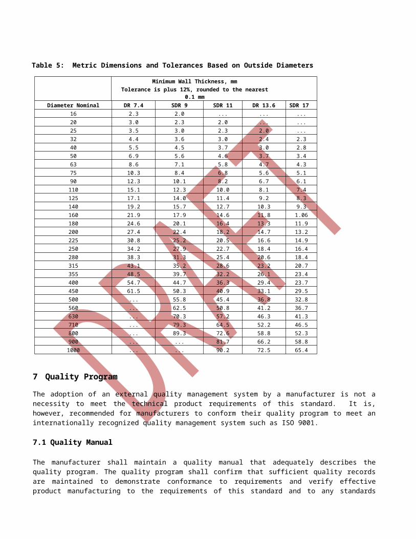
Table 5: Metric Dimensions and Tolerances Based on Outside Diameters
Minimum Wall Thickness, mmTolerance is plus 12%, rounded to the nearest 0.1 mm
Diameter Nominal DR 7.4 SDR 9 SDR 11 DR 13.6 SDR 1716 2.3 2.0 ... ... ...20 3.0 2.3 2.0 ... ...25 3.5 3.0 2.3 2.0 ...32 4.4 3.6 3.0 2.4 2.340 5.5 4.5 3.7 3.0 2.850 6.9 5.6 4.6 3.7 3.463 8.6 7.1 5.8 4.7 4.375 10.3 8.4 6.8 5.6 5.190 12.3 10.1 8.2 6.7 6.1
110 15.1 12.3 10.0 8.1 7.4125 17.1 14.0 11.4 9.2 8.3140 19.2 15.7 12.7 10.3 9.3160 21.9 17.9 14.6 11.8 1.06180 24.6 20.1 16.4 13.3 11.9200 27.4 22.4 18.2 14.7 13.2225 30.8 25.2 20.5 16.6 14.9250 34.2 27.9 22.7 18.4 16.4280 38.3 31.3 25.4 20.6 18.4315 43.1 35.2 28.6 23.2 20.7355 48.5 39.7 32.2 26.1 23.4400 54.7 44.7 36.3 29.4 23.7450 61.5 50.3 40.9 33.1 29.5500 ... 55.8 45.4 36.8 32.8560 ... 62.5 50.8 41.2 36.7630 ... 70.3 57.2 46.3 41.3710 ... 79.3 64.5 52.2 46.5800 ... 89.3 72.6 58.8 52.3900 ... ... 81.7 66.2 58.81000 ... ... 90.2 72.5 65.4
7 Quality Program
The adoption of an external quality management system by a manufacturer is not a necessity to meet the technical product requirements of this standard. It is, however, recommended for manufacturers to conform their quality program to meet an internationally recognized quality management system such as ISO 9001.
7.1 Quality Manual
The manufacturer shall maintain a quality manual that adequately describes the quality program. The quality program shall confirm that sufficient quality records are maintained to demonstrate conformance to requirements and verify effective product manufacturing to the requirements of this standard and to any standards incorporated into this standard by reference. Quality records shall remain legible, readily identifiable and retrievable for a period of not less than 10 years or as specified by an external quality system.
7.2 Quality Control Tests
7.2.1 Conditioning
Test specimens shall be conditioned at 23 ± 2 °C (73.4 ± 3.6 °F) prior to testing for a minimum of 1 hour in water or 4 hours in air at 73.4 ± 3.6 °F (23 ± 2 °C).
7.2.2 Quality Control Testing
Dimensional AnalysisSamples for quality control testing shall be conditioned in accordance with 7.2.1 or in accordance with ASTM D2122.
7.2.3 Pipe Requirements and Frequency
7.2.3.1 Physical Properties
a) Sustained Pressure tests shall be conducted for per ASTM D1598 or ISO 1167
b) Sustained Pressure testing of product materials and extrusion technique qualification shall be performed when a PEX pipe material designation code is first used in a manufacturing facility to manufacture pipe or tubing and in two separate trials during the year, such that the tests generally represent a first half or a second half of the annual production at the facility.
c) The test sample shall consist of three specimens of a generally representative pipe or tubing size produced at the manufacturer’s facility using a material designation code according to Table 1. test according to Table 7 condition for all three specimens using water as the testing medium per ASTM D1598.
d) Passing results are (1) non-failure for all three specimens at a time equal to or greater than the “minimum average time before failure,” or (2) not more than one ductile specimen failure and the average time before failure for all three specimens shall be greater than the specified “minimum average time before failure” for the selected Table 7 condition. For Table 7, Condition 1 through 5: If more than one ductile failure occurs before the “minimum average time before failure,” it is permissible to conduct one retest at a Table 7 condition of lower stress and longer “minimum average time before failure” for the material designation code. For Table 7, Condition 6, no retest is possible. Brittle failure of any specimen in the test sample when tested at Table 7, Condition 1 through 6 constitutes failure to meet this requirement.
e) Except as provided in items a, b, c and d above, if the results of any test(s) do not meet the requirements of this specification, the test(s) may be conducted again in accordance with an agreement between the purchaser and the seller. There shall be no agreement to lower the minimum requirement of the specification by such means as omitting tests that are a part of the specification, substituting or modifying a test method, or by changing the specification limits. In retesting, the product requirements of this specification shall be met, and the test methods designated in the specification shall be followed. If, upon retest, failure occurs, the quantity of the product represented by the test(s) does not meet the requirements of this specification.
7.2.3.2 Test Description and Frequency for Pipe
The following tests shall be conducted per the prescribed frequencies indicated in Table 7.
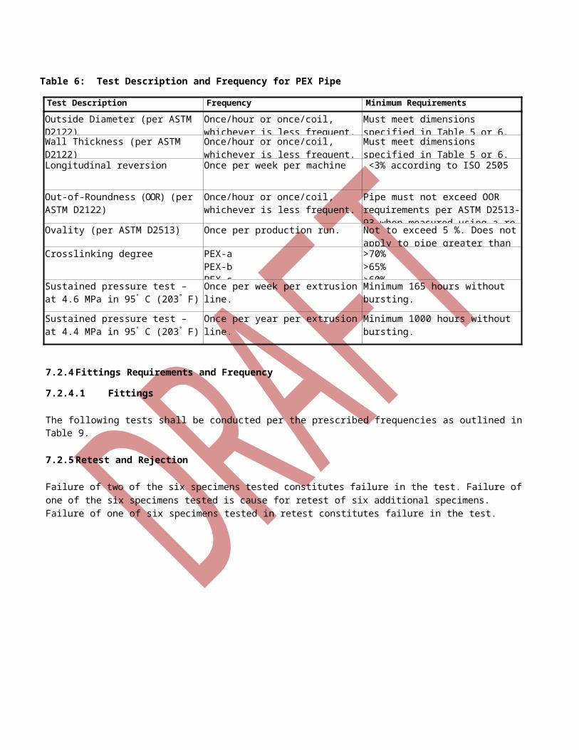
Table 6: Test Description and Frequency for PEX Pipe
Test Description Frequency Minimum Requirements
Outside Diameter (per ASTM D2122) Once/hour or once/coil, whichever is less frequent.
Must meet dimensions specified in Table 5 or 6.
Wall Thickness (per ASTM D2122) Once/hour or once/coil, whichever is less frequent.
Must meet dimensions specified in Table 5 or 6.
Longitudinal reversion Once per week per machine <3% according to ISO 2505
Out-of-Roundness (OOR) (per ASTM D2122)
Once/hour or once/coil, whichever is less frequent.
Pipe must not exceed OOR requirements per ASTM D2513-93 when measured using a re-rounding device, if necessary.
Ovality (per ASTM D2513) Once per production run. Not to exceed 5 %. Does not apply to pipe greater than 3 in. IPS.
Crosslinking degree PEX-aPEX-bPEX-c
>70%>65%>60%
Sustained pressure test – at 4.6 MPa in 95° C (203° F)
Once per week per extrusion line. Minimum 165 hours without bursting.
Sustained pressure test – at 4.4 MPa in 95° C (203° F)
Once per year per extrusion line. Minimum 1000 hours without bursting.
7.2.4 Fittings Requirements and Frequency
7.2.4.1 Fittings
The following tests shall be conducted per the prescribed frequencies as outlined in Table 9.
7.2.5 Retest and Rejection
Failure of two of the six specimens tested constitutes failure in the test. Failure of one of the six specimens tested is cause for retest of six additional specimens. Failure of one of six specimens tested in retest constitutes failure in the test.
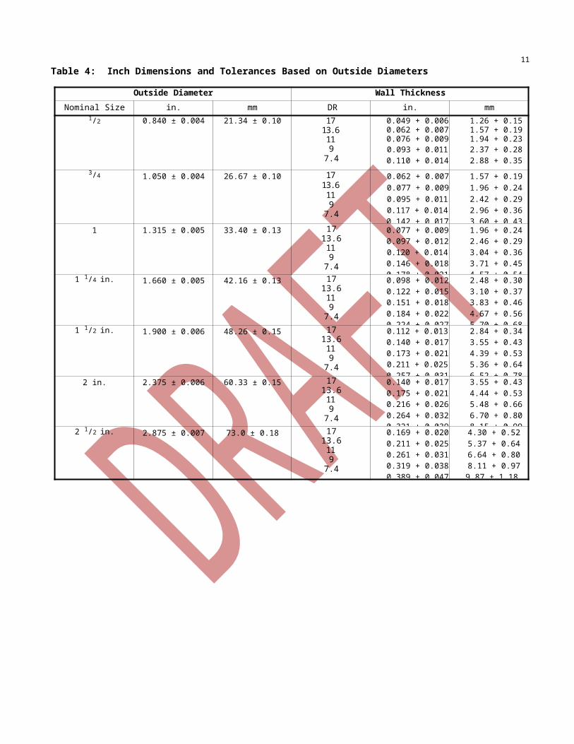
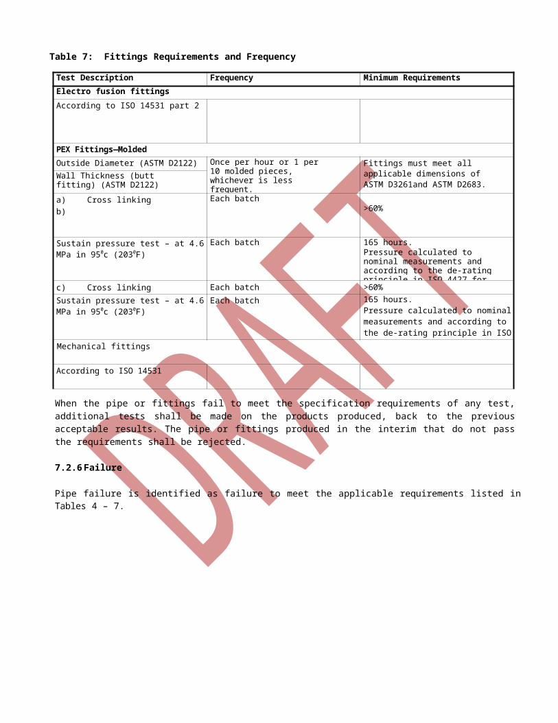
Table 7: Fittings Requirements and Frequency
Test Description Frequency Minimum RequirementsElectro fusion fittingsAccording to ISO 14531 part 2
PEX Fittings—MoldedOutside Diameter (ASTM D2122) Once per hour or 1 per 10
molded pieces, whichever is less frequent.
Fittings must meet all applicable dimensions of ASTM D3261and ASTM D2683.Wall Thickness (butt fitting)
(ASTM D2122)
a) Cross linkingb)
Each batch>60%
Sustain pressure test – at 4.6 MPa in 950c (2030F)
Each batch 165 hours.Pressure calculated to nominal measurements and according to the de-rating principle in ISO 4427 for P.E.
c) Cross linking Each batch >60%
Sustain pressure test – at 4.6 MPa in 950c (2030F)
Each batch 165 hours.Pressure calculated to nominal measurements and according to the de-rating principle in ISO 4427 for P.E.
Mechanical fittings
According to ISO 14531
When the pipe or fittings fail to meet the specification requirements of any test, additional tests shall be made on the products produced, back to the previous acceptable results. The pipe or fittings produced in the interim that do not pass the requirements shall be rejected.
7.2.6 Failure
Pipe failure is identified as failure to meet the applicable requirements listed in Tables 4 – 7.
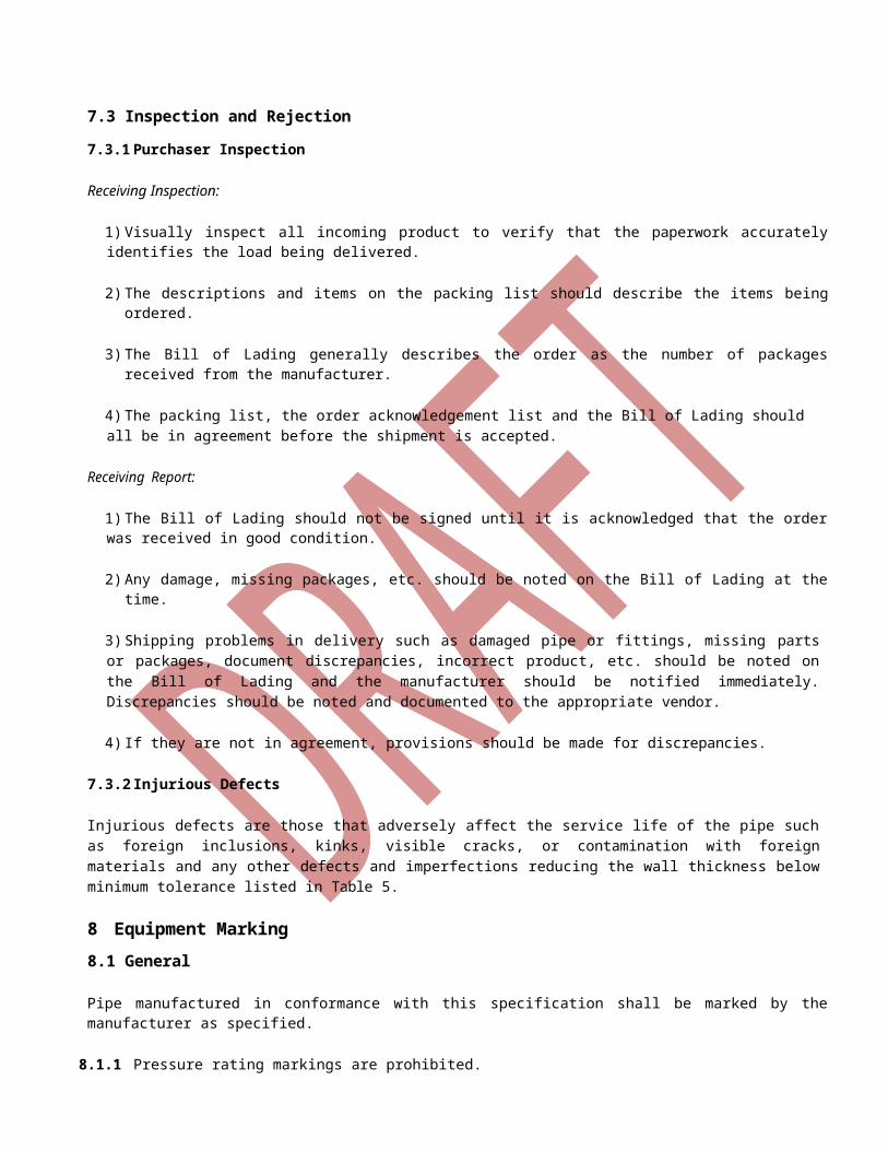
7.3 Inspection and Rejection
7.3.1 Purchaser Inspection
Receiving Inspection:
1) Visually inspect all incoming product to verify that the paperwork accurately identifies the load being delivered.
2) The descriptions and items on the packing list should describe the items being ordered.
3) The Bill of Lading generally describes the order as the number of packages received from the manufacturer.
4) The packing list, the order acknowledgement list and the Bill of Lading should all be in agreement before the shipment is accepted.
Receiving Report:
1) The Bill of Lading should not be signed until it is acknowledged that the order was received in good condition.
2) Any damage, missing packages, etc. should be noted on the Bill of Lading at the time.
3) Shipping problems in delivery such as damaged pipe or fittings, missing parts or packages, document discrepancies, incorrect product, etc. should be noted on the Bill of Lading and the manufacturer should be notified immediately. Discrepancies should be noted and documented to the appropriate vendor.
4) If they are not in agreement, provisions should be made for discrepancies.
7.3.2 Injurious Defects
Injurious defects are those that adversely affect the service life of the pipe such as foreign inclusions, kinks, visible cracks, or contamination with foreign materials and any other defects and imperfections reducing the wall thickness below minimum tolerance listed in Table 5.
8 Equipment Marking8.1 General
Pipe manufactured in conformance with this specification shall be marked by the manufacturer as specified.
8.1.1 Pressure rating markings are prohibited.
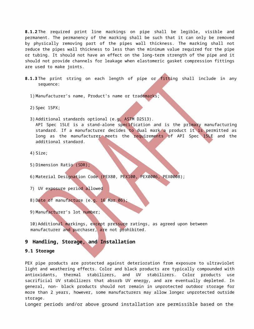
8.1.2 The required print line markings on pipe shall be legible, visible and permanent. The permanency of the marking shall be such that it can only be removed by physically removing part of the pipes wall thickness. The marking shall not reduce the pipes wall thickness to less than the minimum value required for the pipe or tubing. It should not have an effect on the long-term strength of the pipe and it should not provide channels for leakage when elastomeric gasket compression fittings are used to make joints.
8.1.3 The print string on each length of pipe or fitting shall include in any sequence:
1) Manufacturer’s name, Product’s name or trademarks;
2) Spec 15PX;
3) Additional standards optional (e.g. ASTM D2513). API Spec 15LE is a stand-alone specification and is the primary manufacturing standard. If a manufacturer decides to dual mark a product it is permitted as long as the manufacturer meets the requirements of API
Spec 15LE and the additional standard.
4) Size;
5) Dimension Ratio (SDR);
6) Material Designation Code (PEX80, PEX100, PEX0006, PEX0008);
7) UV exposure period allowed
8) Date of manufacture (e.g. 16 Mar 06);
9) Manufacturer’s lot number;
10) Additional markings, except pressure ratings, as agreed upon between manufacturer and purchaser, are not prohibited.
9 Handling, Storage, and Installation9.1 Storage
PEX pipe products are protected against deterioration from exposure to ultraviolet light and weathering effects. Color and black products are typically compounded with antioxidants, thermal stabilizers, and UV stabilizers. Color products use sacrificial UV stabilizers that absorb UV energy, and are eventually depleted. In general, non- black products should not remain in unprotected outdoor storage for more than 2 years, however, some manufacturers may allow longer unprotected outside storage. Longer periods and/or above ground installation are permissible based on the agreement between the costumer and manufacturer.
9.2 Handling
PEX piping materials are lightweight compared to similar piping materials made of steel but larger pieces and components can be heavy. Lifting and handling equipment must have adequate rated capacity to lift and move components from the truck to onsite or temporary storage. Equipment such as a forklift, a crane, a side boom tractor, or an extension boom crane is used for unloading.
5API Spec 15LE is a stand-alone specification and is the primary manufacturing standard. If a manufacturer decides to dual mark a product it is permitted as long as the manufacturer meets the requirements of API Spec 15LE and the additional standard.
When using a forklift, or forklift attachments on equipment such as articulated loaders or bucket loaders, lifting capacity must be adequate at the load center on the forks. Before lifting or transporting the load, forks should be spread as wide apart as practical, forks should extend completely under the load, and the load should be as far back on the forks as possible. Care should be taken not to damage the load with the forks.
9.3 Installation
Discussion of installation requirements is contained in informative Annex E.
Annex A(informative)
Conversions
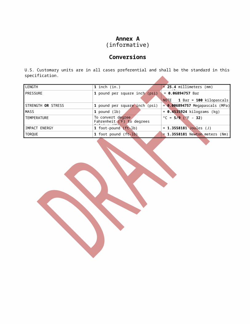
U.S. Customary units are in all cases preferential and shall be the standard in this specification.
LENGTH 1 inch (in.) = 25.4 millimeters (mm) exactlyPRESSURE 1 pound per square inch (psi) = 0.06894757 Bar
NOTE 1 Bar = 100 kilopascals (kPa)
STRENGTH OR STRESS 1 pound per square inch (psi) = 0.006894757 Megapascals (MPa)
MASS 1 pound (lb) = 0.4535924 kilograms (kg)
TEMPERATURE To convert degree Fahrenheit (F) to degrees Celsius (C):
ºC = 5/9 (ºF – 32)
IMPACT ENERGY 1 foot-pound (ft-lb) = 1.3558181 Joules (J)
TORQUE 1 foot pound (ft-lb) = 1.3558181 Newton meters (Nm)
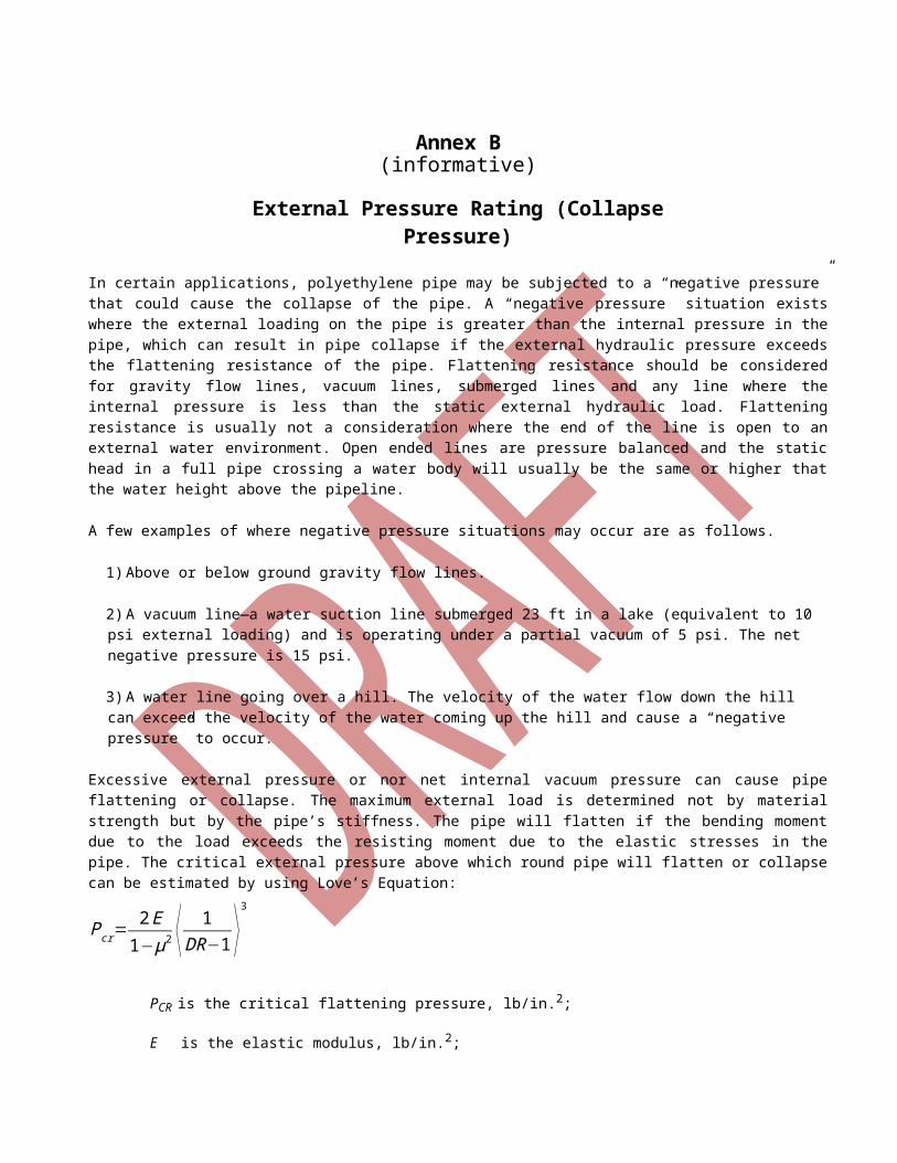
Annex B(informative)
External Pressure Rating (Collapse Pressure)
In certain applications, polyethylene pipe may be subjected to a “negative pressure” that could cause the collapse of the pipe. A “negative pressure” situation exists where the external loading on the pipe is greater than the internal pressure in the pipe, which can result in pipe collapse if the external hydraulic pressure exceeds the flattening resistance of the pipe. Flattening resistance should be considered for gravity flow lines, vacuum lines, submerged lines and any line where the internal pressure is less than the static external hydraulic load. Flattening resistance is usually not a consideration where the end of the line is open to an external water environment. Open ended lines are pressure balanced and the static head in a full pipe crossing a water body will usually be the same or higher that the water height above the pipeline.
A few examples of where negative pressure situations may occur are as follows.
1) Above or below ground gravity flow lines.
2) A vacuum line—a water suction line submerged 23 ft in a lake (equivalent to 10 psi external loading) and is operating under a partial vacuum of 5 psi. The net negative pressure is 15 psi.
3) A water line going over a hill. The velocity of the water flow down the hill can exceed the velocity of the water coming up the hill and cause a “negative pressure” to occur.
Excessive external pressure or nor net internal vacuum pressure can cause pipe flattening or collapse. The maximum external load is determined not by material strength but by the pipe’s stiffness. The pipe will flatten if the bending moment due to the load exceeds the resisting moment due to the elastic stresses in the pipe. The critical external pressure above which round pipe will flatten or collapse can be estimated by using Love’s Equation:
Pcr=2 E
1−μ2 ⟨ 1DR−1 ⟩
3
PCR is the critical flattening pressure, lb/in.2;
E is the elastic modulus, lb/in.2;
is Poisson’s ratio;
(0.40 for PEX under long-term stress);
(0.35 for PEX under short-term stress);
DR is the pipe Dimension Ratio.
An appropriate safety factor should be applied when using this equation for design. If short-term modulus is used in the calculation, a safety factor of 3 would be typical. If a long-term value of modulus is available, this may be reduced to 1.5.
For above ground lines, increased temperatures will decrease the pipe’s collapse resistance and in buried lines, pipe deflection will reduce flattening resistance.
Annex C(informative)
Cross-linked Polyethylene
This annex discusses how cross-linked polyethylene fits into the general methodology used with polyethylene in this document. This information is informative, rather than normative.
Polyethylene line pipe may be crosslinked by a number of industry-proven means to increase temperature resistance. These include:
1) peroxide crosslinking (PEX-a);
2) moisture-cured vinylsilane (PEX-b);
3) beta-irradiation (PEX-c).
Polyethylene line pipe that has been crosslinked by one of these means should conform to this specification and meet the following additional requirements.
C.3.1 Definitions
C.3.1.1crosslinkingThe process by which the adjacent polymer chains of a polyethylene plastic are joined to produce an insoluble, unmeltable, three-dimension polymer network.
C.3.2 Abbreviations
PEX Cross-linked Polyethylene
XLPE Cross-linked Polyethylene
C.5.1.4 Temperature Service Factors
DSFs, such as those shown in Table 1, shall be determined by hydrostatic regression testing. The test fluid environment shall be maintained on the inside of the pipe with fluid, air or water outside. As a minimum, the data set shall cover the E-2 requirements set forth by PPI TR-3.
C.5.1.5 Hydrostatic Strength
Materials designated as PEX0006 meeting this specification have a HDS of 1250 psi (8.6 MPa) for water at 73 °F (23 °C). After applying a 0.5 design service factor, the design stress rating at 73 °F (23 °C) will be 630 psi (4.3 MPa). Materials designated as PEX0008 meeting this specification have a HDS of 1600 psi (11.0 MPa) for water at 73 °F (23 °C). After applying a 0.5 design service factor, the design stress rating at 73 °F (23 °C) will be 800 psi (5.5 MPa). Due to the improved resistance to stress cracking upon crosslinking, validation of the HDS by the Rate Process Method is not required for PEX compounds.
Additional long-term stress rupture testing shall be performed up the materials maximum operational temperatures, not to exceed 210 °F, and evaluated in accordance with the requirements of Method ASTM D2837 with the 100,000 hour intercept not less than 600 psi.
C.6.2 Material
Crosslinked polyethylene line pipe shall be listed in the PPI TR-4.
C.6.3 Rework Material
Due to crosslinking of the material during extrusion, no rework material is permitted for PEX-a and PEX-b materials. Clean PEX-c rework materials are permitted only as defined by 6.3.
C.6.4 Fittings
Plastic fusion fittings for use with this pipe must be fabricated from a PEX material made from the same crosslinking process and with the same Type and Class designation. All fittings, plastic or metallic, must be demonstrated by the pipe manufacturer to meet or exceed the thermal and mechanical properties of the pipe.
C.6.6 Special Processes
Crosslinking of the PEX-b materials may be facilitated by the use of increased temperatures and/or humidity using steam or hot water immersion.
C.7.4.3.2 Test Description and Frequency
In addition to the requirements in 7.4.3.2, the following tests shall be conducted per the prescribed frequencies.
1) Property: Gel Content. Method: ASTM D2765.
2) Frequency: Once every hour or once every coil, whichever is less frequent.
When tested in accordance with ASTM D2765, the degree of crosslinking for PEX pipe material shall be within the range from 65 % to 89 %, inclusive. Depending on the process used, the following minimum percentage crosslinking values shall be achieved: 70 % for PEX-a, 65 % for PEX-b or 65 % for PEX-c.
Annex D(informative)
API Monogram
D.1 Introduction
The API Monogram Program allows an API Licensee to apply the API Monogram to products. The use of the Monogram on products constitutes a representation and warranty by the Licensee to purchasers of the products that, on the date indicated, the products were produced in accordance with a verified quality management system and in accordance with an API product specification. The API Monogram Program delivers significant value to the international oil and gas industry by linking the verification of an organization's quality management system with the demonstrated ability to meet specific product specification requirements.
When used in conjunction with the requirements of the API License Agreement, API Specification Q1, including this Annex, defines the requirements for those organizations who wish to voluntarily obtain an API License to provide API monogrammed products in accordance with an API product specification.
API Monogram Program Licenses are issued only after an on-site audit has verified that the Licensee conforms to the requirements described in API Spec Q1 in total.
For information on becoming an API Monogram Licensee, please contact API, Certification Programs, 1220 L Street,N. W., Washington, D.C. 20005 or call 202-682-8000 or by email at [email protected].
D.2 API Monogram Marking Requirements
These marking requirements apply only to those API licensees wishing to mark their products with the API Monogram. Each length of pipe or fitting shall be marked with the following:
1) Spec 15LE;
2) API license number;
3) additional standards optional6 (e.g. ASTM D2513);
4) size;
5) Dimension Ratio (SDR);
6) Material Designation Code (e.g. PE2708, PE3608, PE3708, PE3710, PE4708, PE4710);
7) color and UV stabilizer (C or E);
8) date of manufacture (e.g. 16 Mar 06);
9) manufacturer’s lot number;
10) additional markings, except pressure ratings, as agreed upon between manufacturer and purchaser, are not prohibited.
6API Spec 15LE is a stand-alone specification and is the primary manufacturing standard. If a manufacturer decides to dual mark
a product it is permitted as long as the manufacturer meets the requirements of API Spec 15LE and the additional standard.
Annex E(informative)
Installation
E.1 Support Spacing
Above grade applications frequently require non-continuous support for PEX pipe. These type applications usually involve piping in pipe racks, trestles, on sleepers, or suspended from overhead structures. Where applicable the structures should provide proper pipeline support, accommodate thermal expansion and contraction and provide structural support spacing that limits the vertical deflection and movement between supports.
Supports for PEX pipe should cradle at least the bottom 120° of the pipe, and be at least 1/2 pipe diameter wide. Edges should be rounded or rolled to prevent cutting into the pipe. Commercial pipe supports such as U-bolts, narrow strap-type hangers, and roller type supports are unsuitable unless modified for width and cradling. The weight of the pipe and its contents must be distributed over a broad surface. Narrow support surfaces can produce high concentrated stress (point loading), and can possibly lead to pipeline failure.
Pipes supported in an overhead rack require design consideration for both support spacing and thermal length change. Support beams are spaced according to vertical deflection limits, and the rack width accommodates the total thermal expansion offset plus the diameter of the pipe. Pipe supports should be allowed to move along support beams, or otherwise accommodate horizontal movement as the pipe deflects laterally with changing temperature.
When not supported continuously in horizontal runs, hangers and brackets should be used according to the manufacturer recommendations taking the different fluids transported in the pipe and the different temperatures.
E.2 Joining
PEX (PE) pipe can be joined to other PEX pipe or fittings or to pipe or appurtenances of other materials by selecting one or more of the following joining systems: electrofusion, , and mechanical methods such as gasketed bell-and-spigot joints, flanges, and compression couplings. Joining and connection methods will vary depending upon requirements for internal or external pressure, leak tightness, restraint against longitudinal movement (thrust load capacity), gasketing requirements, construction and installation requirements, and the product. The procedures provided below reference and incorporate information from the following documents.
1) PPI, “PEX PIPE DESIGN MANUAL For Water, Oil, Gas & Industrial Applications”
2) ISO 14531 part 2 and 3.
When present, liquid hydrocarbons may permeate (solvate) PEX pipe. Liquid hydrocarbon permeation may occur when liquid hydrocarbons are present in the pipe, when soil surrounding the pipe is contaminated with liquid hydrocarbons, or when liquid hydrocarbon condensates form in gas pipelines. All types of liquid hydrocarbons (aromatic, paraffinic, etc.) have a similar effect, and the relative effect on different PEX pipe resins is essentially the same.
Heat fusion joining to liquid hydrocarbon permeated pipes may result in a low strength joint. Hydrocarbon permeated lines requiring repair should not be repaired using heat fusion joining or electrofusion joining methods. Mechanical fittings should be used to join or repair hydrocarbon permeated lines.
E.2.2 Electrofusion
The electrofusion welding procedure differs somewhat from the conventional fusion joining procedures described above. The main difference between conventional heat fusion and electrofusion is the method by which the heat is applied. In conventional heat fusion joining, a heating tool is used to heat the pipe and fitting surfaces. The electrofusion joint is heated internally, either by a conductor at the interface of the joint or, as in one design, by a conductive polymer. Heat is created as an electric current is applied to the conductive material in the fitting.
Electrofusion is frequently used in oilfield applications where liquid hydrocarbon permeation has occurred in the interior pipe wall. It is also used where both pipes are constrained, such as for repairs or tie-in joints in the trench. Joints made between dissimilar polyethylene brands or grades are also made using electrofusion, as the procedure readily accommodates polyethylenes with different melt flow rates.
Electrofusion joining should be performed using the following the manufacturer installation instructions and training.
E.2.3 Flanging
Flanging is used when it is necessary to join polyethylene to steel, fiberglass and other piping materials that require an ANSI 150-lb flange connection. Flanging is also an option when it is required that a pipe section is capable of being disassembled for maintenance or where calculated accelerated wear requires fitting removal. The polyethylene flange adapter and back-up ring is a 2-part fitting that is designed so that one end is fusion welded to the polyethylene pipe and the other end is a flange-type configuration with a metal back-up ring that allows bolting to an ANSI 150-lb flange. (DR-5 400-psi application requires the use of ANSI 300-lb back-up rings or ANSI 300-lb lap joint flanges.)
Polyethylene flanges that do not incorporate the use a back-up ring are not recommended because polyethylene flanges require uniform pressure over the entire sealing surface. Without a back-up ring, a polyethylene flange could leak between the bolts.
A flange gasket may not be required for flanging polyethylene to polyethylene, especially at pressures below 80 psi. A flange gasket is always recommended when flanging polyethylene to any other material. Gasket manufacturers may be contacted to ensure that the intended service is recommended for the gasket material chosen and to confirm that the gasket material hardness is correct for the bolting pressures. Hard gaskets that require high bolting pressures may not seal when used with polyethylene flange adapters.
E.3 Trench Installation
Underground installations usually require trench excavation.
placing embedment backfill around the pipe is not required (also stated in ISO 14531 part 4).
There are many site and project specific parameters that affect the installation of PEX pipe. Pipe application and service requirements, size, type, soil conditions, backfill soil quality, burial depth and joining requirements all affect the installation.
E.4 Leak Test (Hydrostatic and Pneumatic Testing)
The premise of a leak test for polyethylene piping system is to locate any unacceptable fault in the system before
it is put into service. A leak test should not be used to verify system pressure rating on existing pipe or potential application for service in existing pipe. The system design and the pipe pressure ratings using the equations found in Section 5 of this standard determine the systems pressure rating and long term performance. If leaks exist they usually occur in the joints or in connection to appurtenances in the system.
Pipeline failure during a leak test can be violent and dangerous. Especially if one is using pressurized gas for testing such as compressed air or nitrogen. When testing with compressed gas both the pressure stress on the system and the energy used to compress the gas are released at failure. The release is potentially violent and can be catastrophic. Where possible, a hydrostatic leak test should always be considered before a compressed gas leak test. Hydrostatic leak testing with water is the recommended and preferred method of testing.
E.4.1 References
1) PPI, “PEX PIPE DESIGN MANUAL For Water, Oil, Gas & Industrial Applications”2) ASME B31.3, Process Piping
E.4.2 Precautions
Where hydrostatic leak testing is required the following precautions are recommended: A more detailed procedure may be obtained by checking either of the above standards and guidelines.
1) the piping system under test should be checked to ensure that sections are fully restrained against sudden movement in case of rupture;
2) all air should be removed from the system before hydrostatic leak testing begins;
3) all electro fusion joints should be fully cooled before testing begins;
4) mechanical connections must be restrained and tied-in;
5) all fittings and appurtenances in the system should be verified to meet the test pressure;
6) all safety precautions to protect personnel in case of rupture should be in place: including suitable personal protective gear to prevent injury;
7) keep personnel a safe distance away during pneumatic testing.
E.4.3 Test Pressure
1) The maximum hydrostatic test pressure should be measured at the lowest point in the system.
2) The maximum hydrostatic leak test pressure is the lowest of:
a) 150 % of the system design operating pressure;
b) the pressure rating of the lowest rated component in the system.
3) The authority having jurisdiction may determine the maximum test pressure, as long as the test pressure does not exceed 150 % of the pipe’s PR.
4) Elevated temperatures may reduce the maximum test pressure allowed depending on the specific site conditions.
E.4.4 Test Procedure (Hydrostatic)
1) Observe all safety precautions and site-specific safety regulations.
2) Remove all air from the test section by slowly filling with water and allowing entrapped air to escape through
air release devices.
3) When the line is filled with water and all air is removed, gradually fill the pipe to the test pressure.
4) Maintain the pipe at test pressure for 3 hours. This is called the initial expansion phase. During this phase the polyethylene will expand slightly and the pressure will decrease. To maintain test pressure additional fluid will be required. It is not necessary to monitor the amount of water added during the initial expansion phase.
5) Immediately after the 3-hour Initial expansion phase is complete the test phase begins.
a) Reduce the test pressure by 10 psi.
b) Do not increase pressure or add additional make-up water.
c) Monitor the gauge for the next hour and record if the pressure remains steady (within 5 % of the test pressure).
6) If no visual leakage is indicated and the test pressure remains within 5 % of the test pressure value, the test is declared successful.
E.4.5 Test Procedure (Pneumatic)
1) Carefully consider if pneumatic testing should be authorized.
a) Approval should be sought from the owner and the project engineer.
2) Observe all safety precautions and site-specific safety regulations.
3) Keep personnel a safe distance away during pneumatic testing.
4) The pressure in the test section should be slowly increased to not more than half the system design test pressure.
5) Test pressure is temperature dependent.
6) Gradually increase test pressure in small increments (5 psi) up to 150 % of the system design pressure or to the authorized pneumatic test pressure.
7) Maintain the test pressure for ten (10) to sixty (60) minutes. This is the initial expansion phase for pneumatic testing.
8) Reduce test pressure to the system design pressure or to the authorized pneumatic test pressure and hold the pressure until such time to determine if a leak exists.
9) All safety precautions to protect personnel in case of rupture should be in place: including suitable personal protective gear to prevent injury if failure occurs.
NOTE Under no circumstances shall the total time under test exceed eight (8) hours at 1.5 times the system pressure rating. If the test is not complete during this time frame (due to leakage, equipment failure, etc.), the test section shall be depressurized and permitted to “relax” for eight (8) hours prior to the next test sequence.
E.5 Thermal Expansion and Contraction
The coefficient of thermal expansion and contraction for PEX pipe is about 10 times that of steel pipe. This means that an unrestrained PEX line will expand or contract about ten times the distance of a comparable steel pipe. When polyethylene pipe is restrained, the stresses developed due to expansion and contraction are considerably less than those of a steel line. This is due to the lower Modulus of Elasticity of PEX pipe compared to steel pipe. When PEX is properly anchored and restrained changes in temperature and the related expansion and
contraction have no adverse effect.
The equation to calculate expansion and contraction for polyethylene is given by:
ΔL = LαΔT
where
ΔL is the length change, in.;
L is the pipe length, in.;
α is the thermal expansion coefficient, in./in./°F (7.94 × 10⁻⁵ in./in./°F);
ΔT is the temperature change, °F.
ANNEX F(informative)
3.1.3.2 standard pipe material designation code—The pipe material designation code shall consist of the abbreviation for the type of plastic (PEX) followed by four Arabic digits that describe short-term properties in accordance with applicable ASTM standards and as shown in Table 1.
TABLE 1 Material Designation Code CellsProperty Standar
d0 1 2 3 4 5 6 7 8 9
Chlorine Resistance
F2023 Not tested or rated
75 % at 73°F
and 25 % at 140°F
Reserved
50 % at 73°F
and 50 % at 140°F
Reserved
100 % at 140°F
... ... ... ...
Reserved ... ... ... ... ... ... ... ... ... ... ...
HDS for water at 73°F
... ... ... ... ... ... ... 630 ... 800 ...
3.1.3.2.1 Discussion—The first digit is for chlorine resistance tested in accordance with Test Method F2023. (1) A digit “0” indicates that the PEX pipe either has not been tested for chlorine resistance or that the PEX pipe does not
meet the minimum requirement for chlorine resistance. (2) A digit “1” indicates the PEX pipe has been tested and meets the F XXXX requirement for minimum chlorine resistance
at the end use condition of 25% at 140°F (60°C) and 75% at 73°F (23°C). (3) A digit “2” is reserved for future application. (4) A digit “3” indicates that the PEX pipe has been tested and meets the F XXXX requirement for minimum chlorine
resistance at end use condition of 50% at 140°F and 50% at 73°F. (5) A digit “4” is reserved for future application. (6) A digit “5” indicates that the PEX pipe has been tested and meets the requirement for minimum chlorine resistance at end
use conditions of 100% of the time at 140°F. 3.1.3.2.2 Discussion—The second digit is a "0". This digit is reserved for a currently unspecified PEX pipe property.3.1.3.2.3 Discussion—The last two digits are the hydrostatic design stress (HDS) for water at 73°F (23°C) in units of 100 psi
with any decimal figures dropped. For this standard PEX has an HDB of either 1600 psi or 1250 psi, which is an HDS of either 800 psi or 630 psi, at 73°F (23°C). Where the hydrostatic design stress code contains less than two figures, a zero is used before the number. Thus, a complete material designation code for PEX pipe shall consist of the three letters "PEX" and four digits, such as PEX 1006.

ANNEX G (Informative)Purchasing Guidelines
GeneralTable 1 provides recommended guidelines for inquiry and purchase of API Spec 15PXpipe or fittings. 7
Table G.1—Purchasing General Guidelines -PipeSpecification API 15PXMaterial PEXPipe Designation Code (HDB or MRS/CRS) e.g. PEX 80 or 0006
Outside Diameter Nominal OD (Project Specific)Standard Dimension Ratio (DR) Required (Project Specific)Order Length Available in Coils or Straight Lengths (Project Specific)
FittingsMolded Fittings (DR) (Project Specific)Fabricated Fittings Must Meet Pressure Rating of Pipe (Project Specific)
ServiceFluid Service (Project Specific)Internal Pressure (Project Specific)Design Temperature (Project Specific)Above Ground/Below Ground Application (Project Specific)
An important consideration for purchasing quality materials for application in oil and gas gathering is the selection of a quality vendor. Vendors should have an understanding of the necessary quality control testing and the capability to perform the testing required by standards.
Vendors should be able to provide records showing that a detailed QA/QC program is in place that utilizes the testing required by API Spec 15PX.
Appropriate records of in-plant inspection and testing and quality control/quality assurance testing should be available to demonstrate that the manufacturer’s piping products meet the requirements of this specification.
Vendors should have the ability to provide sound technical support for its products in field applications.
ANNEX H (REWRITE TO REFLECT DOCUMENT PHOLOSOPHY)
Standard Pressure Rating (informative)
The Standard Pressure Rating of a pipe is the design capacity to resist working pressure at the anticipated operating temperature with sufficient capacity to withstand anticipated positive pressure surges above working pressure. Standard Pressure Rating is calculated using the formula below:
P=[ 2× HDSDo
t−1 ]× FSF × TSF
or P=2 × HDSSDR−1
× FSF ×TSF
where
P is the Standard Pressure Rating (psi);
HDS is the Hydrostatic Design Stress (psi) at 73.4° in water;
Do is the outside diameter (in.);
t is the minimum pipe wall thickness (in.);
SDR is the Standard Dimension Ratio;
FSF is the Fluid Service Factor;
TSF is the Temperature Service Factor, if required by 5.1.4.