1 Front End Capture/Phase Rotation & Cooling Studies David Neuffer Cary Yoshikawa December 2008.
31
1 Front End Front End Capture/Phase Rotation Capture/Phase Rotation & Cooling Studies & Cooling Studies David Neuffer Cary Yoshikawa December 2008
Transcript of 1 Front End Capture/Phase Rotation & Cooling Studies David Neuffer Cary Yoshikawa December 2008.
1
Front EndFront EndCapture/Phase RotationCapture/Phase Rotation
& Cooling Studies & Cooling Studies
David NeufferCary Yoshikawa
December 2008
2
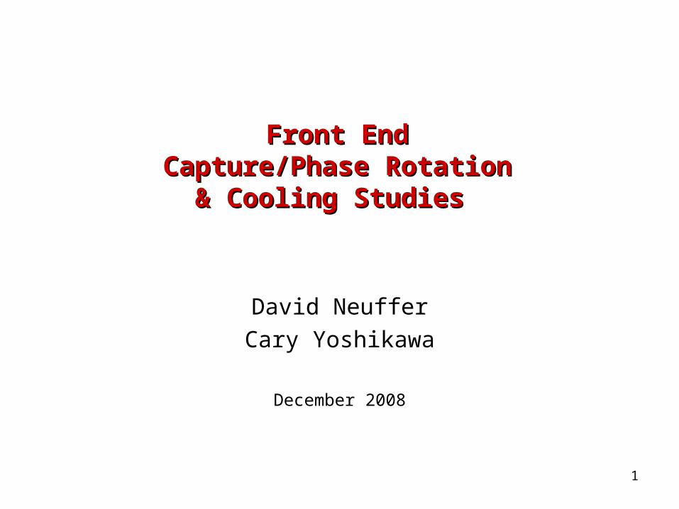
0utline0utline
Introduction ν-Factory Front end
Capture and Φ-E rotation High Frequency
buncher/rotation •Study 2B ν-Factory
Shorter version ν-Factory→μ+-μ- Collider
Discussion
3
Variations tried …Variations tried …
Study 2A – ISS baseline Shorter bunch train example
nB= 10
Better for Collider; as good for ν-Factory ICOOL/G4Beamline simulations Study of “accepted” particles
Rf cavities in solenoids? Use “magnetic insulation” ASOL lattice Not too bad Variations Higher energy capture ??
4
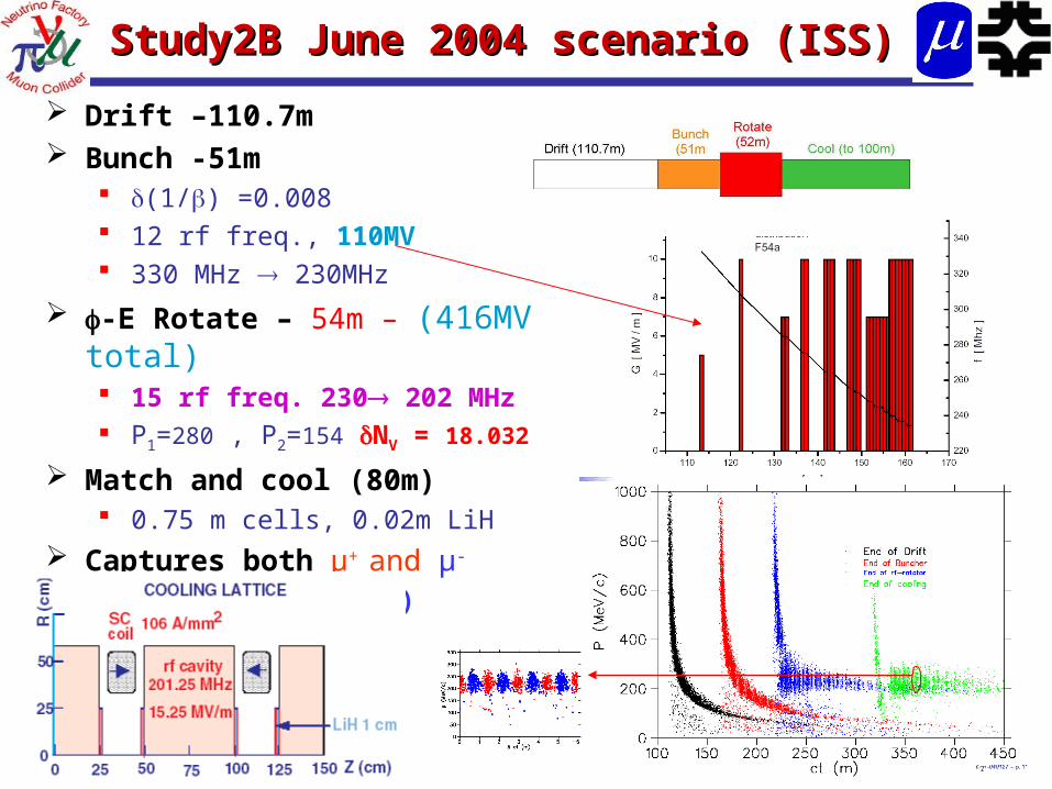
Study2B June 2004 scenario (ISS)Study2B June 2004 scenario (ISS)
Drift –110.7m Bunch -51m
(1/) =0.008 12 rf freq., 110MV 330 MHz 230MHz
-E Rotate – 54m – (416MV total) 15 rf freq. 230 202 MHz P1=280 , P2=154 NV = 18.032
Match and cool (80m) 0.75 m cells, 0.02m LiH
Captures both μ+ and μ-
~0.2 μ/(24 GeV p)
5
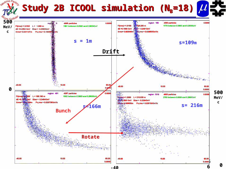
Study 2B ICOOL simulation (NStudy 2B ICOOL simulation (NBB=18)=18)
s = 1m s=109m
s=166m s= 216m
-40 60
500MeV/c
0
Drift
Bunch
Rotate
500MeV/c
0
6
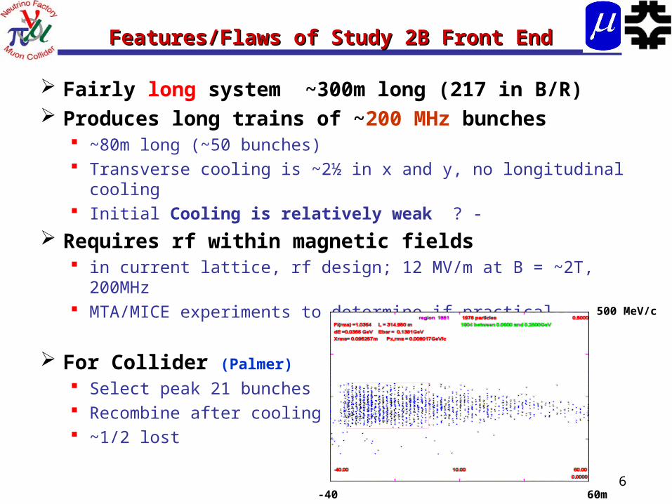
Features/Flaws of Study 2B Front EndFeatures/Flaws of Study 2B Front End
Fairly long system ~300m long (217 in B/R) Produces long trains of ~200 MHz bunches
~80m long (~50 bunches) Transverse cooling is ~2½ in x and y, no longitudinal
cooling Initial Cooling is relatively weak ? -
Requires rf within magnetic fields in current lattice, rf design; 12 MV/m at B = ~2T, 200MHz MTA/MICE experiments to determine if practical
For Collider (Palmer)
Select peak 21 bunches Recombine after cooling ~1/2 lost
-40 60m
500 MeV/c
7
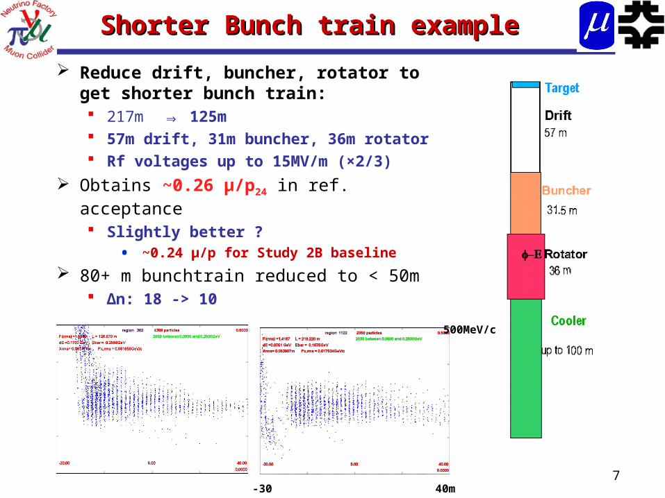
Shorter Bunch train example Shorter Bunch train example
Reduce drift, buncher, rotator to get shorter bunch train: 217m ⇒ 125m 57m drift, 31m buncher, 36m rotator Rf voltages up to 15MV/m (×2/3)
Obtains ~0.26 μ/p24 in ref. acceptance Slightly better ?
• ~0.24 μ/p for Study 2B baseline
80+ m bunchtrain reduced to < 50m Δn: 18 -> 10
-30 40m
500MeV/c
8
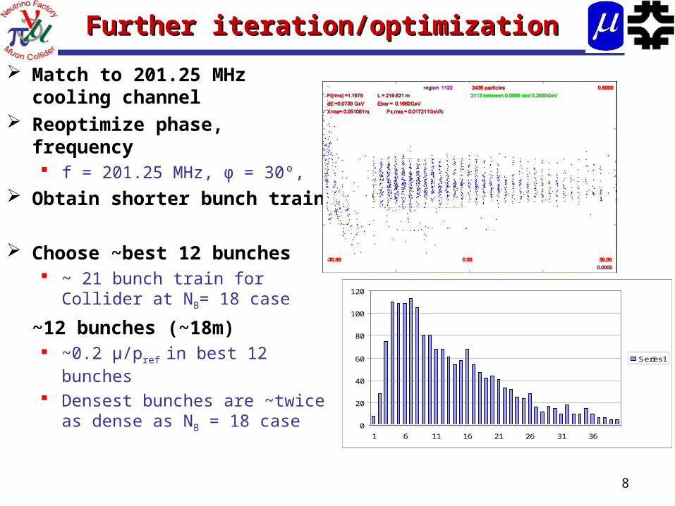
Further iteration/optimizationFurther iteration/optimization
Match to 201.25 MHz cooling channel
Reoptimize phase, frequency f = 201.25 MHz, φ = 30º,
Obtain shorter bunch train
Choose ~best 12 bunches ~ 21 bunch train for Collider
at NB= 18 case
~12 bunches (~18m) ~0.2 μ/pref in best 12 bunches Densest bunches are ~twice
as dense as NB = 18 case0
20
40
60
80
100
120
1 6 11 16 21 26 31 36
Series1
9
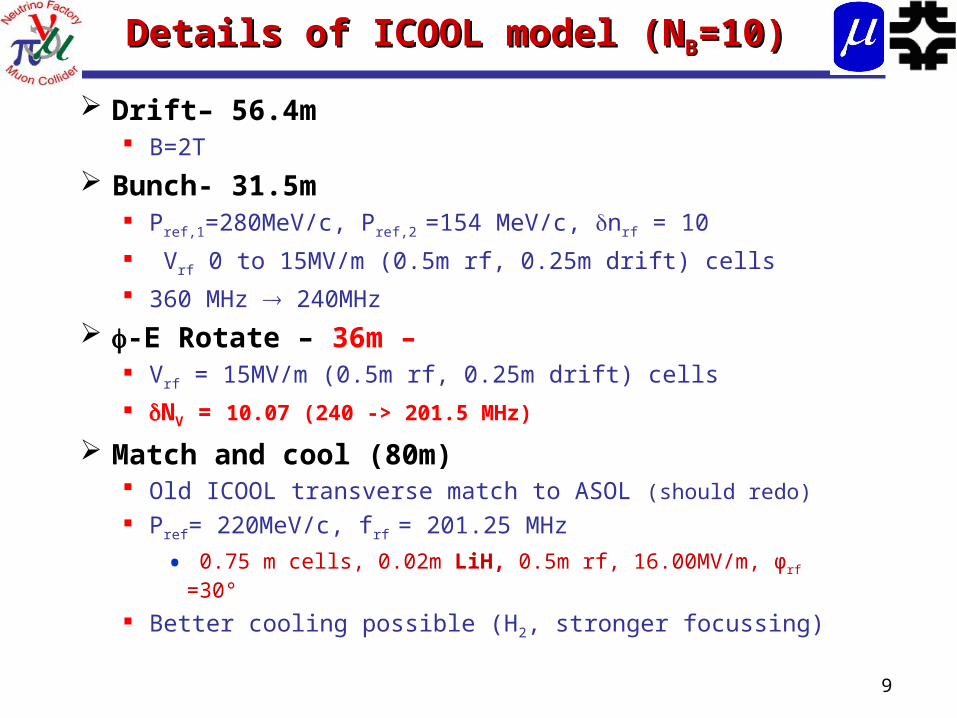
Details of ICOOL model (NDetails of ICOOL model (NBB=10)=10)
Drift– 56.4m B=2T
Bunch- 31.5m Pref,1=280MeV/c, Pref,2 =154 MeV/c, nrf = 10
Vrf 0 to 15MV/m (0.5m rf, 0.25m drift) cells
360 MHz 240MHz
-E Rotate – 36m – Vrf = 15MV/m (0.5m rf, 0.25m drift) cells
NV = 10.07 (240 -> 201.5 MHz)
Match and cool (80m) Old ICOOL transverse match to ASOL (should redo)
Pref= 220MeV/c, frf = 201.25 MHz
• 0.75 m cells, 0.02m LiH, 0.5m rf, 16.00MV/m, φrf =30°
Better cooling possible (H2, stronger focussing)
10
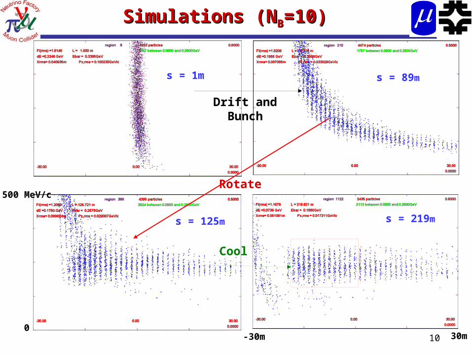
Simulations (NSimulations (NBB=10)=10)
-30m 30m
500 MeV/c
0
Drift andBunch
s = 89ms = 1m
Rotate
s = 125m s = 219m
Cool
11
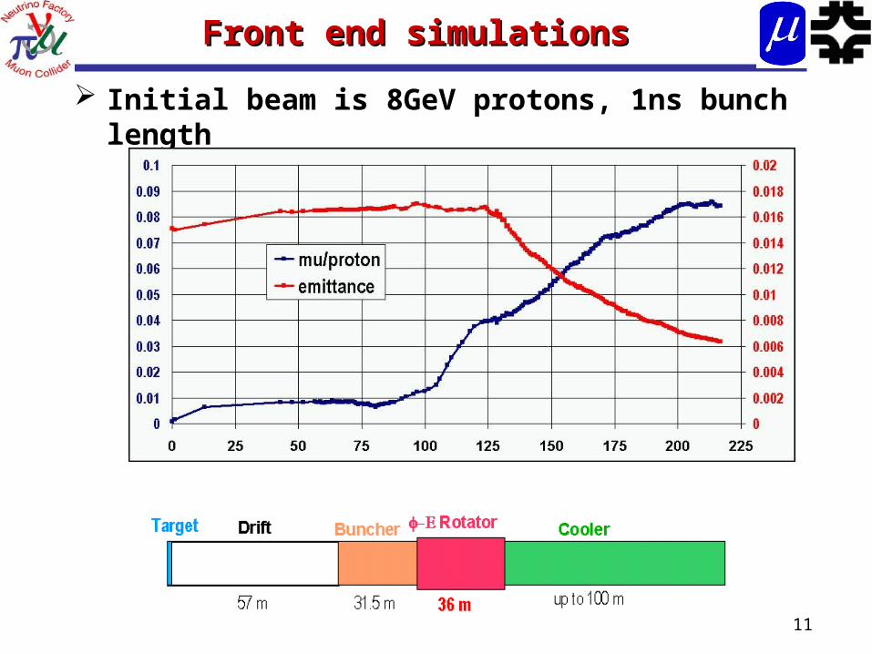
Front end simulationsFront end simulations
Initial beam is 8GeV protons, 1ns bunch length
12
Comparisons of ICOOL and G4BLComparisons of ICOOL and G4BL
Simulations of front end and cooling agree ICOOL and G4Beamline results can be matched
Buncher – rotator – cooler sequence can be developed in both codes
Method Captures both μ+ and μ-
But some differences dE/dx is larger in ICOOL Phasing of rf cavities uses different model
13
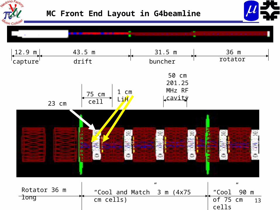
12.9 m 43.5 m 31.5 m 36 m
drift buncher rotatorcapture
MC Front End Layout in G4beamline
“Cool and Match” 3 m (4x75 cm cells) “Cool” 90 m of 75 cm cells
Rotator 36 m long
75 cm cell 1 cm LiH
23 cm vacuum
50 cm 201.25 MHz
RF cavity
14
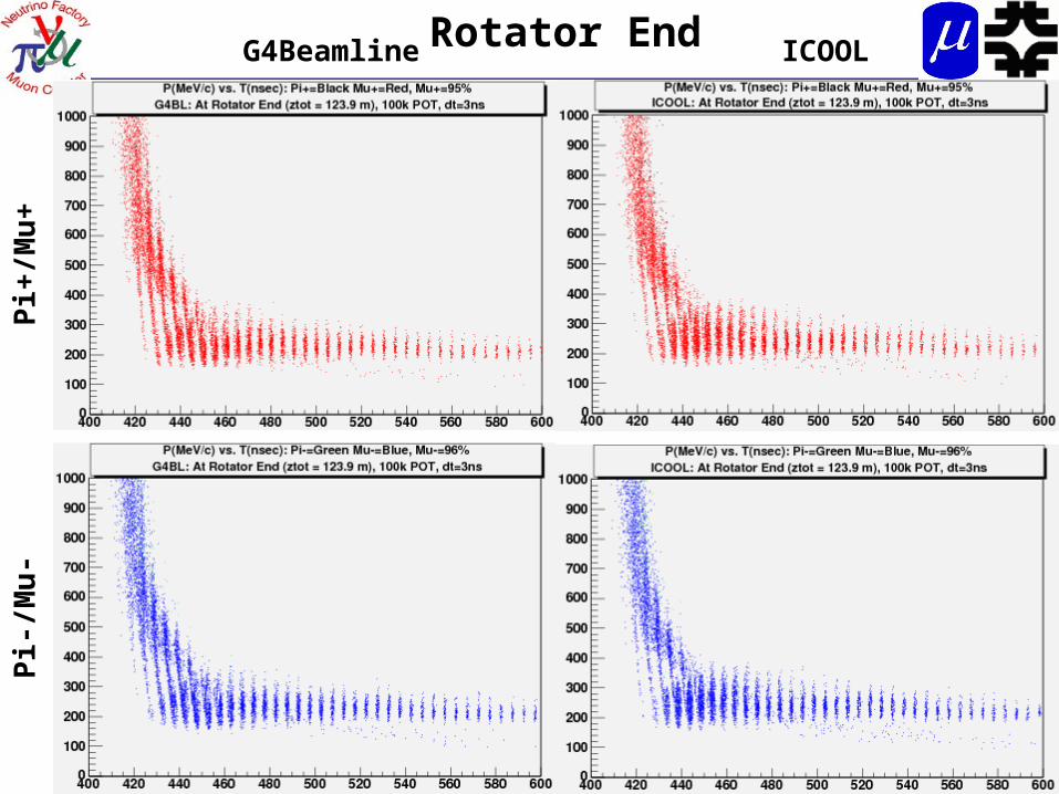
G4Beamline ICOOLP
i+/M
u+
Pi-
/Mu
-Rotator End
15
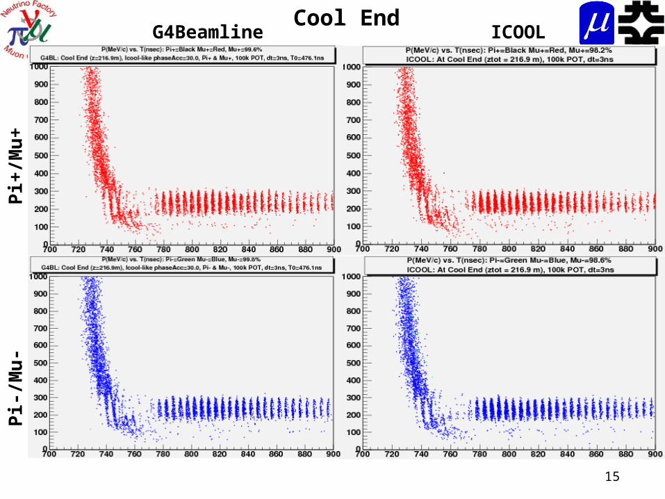
G4Beamline ICOOLP
i+/M
u+
Pi-
/Mu
-Cool End
16
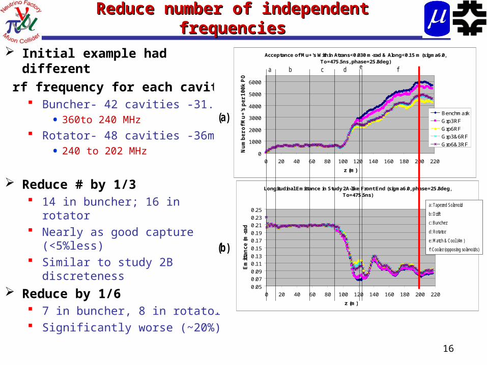
Reduce number of independent Reduce number of independent frequenciesfrequencies
Initial example had different
rf frequency for each cavity Buncher- 42 cavities -31.5m
• 360to 240 MHz Rotator- 48 cavities -36m
• 240 to 202 MHz
Reduce # by 1/3 14 in buncher; 16 in rotator Nearly as good capture
(<5%less) Similar to study 2B
discreteness Reduce by 1/6
7 in buncher, 8 in rotator Significantly worse (~20%)
Acceptance of Mu+'s Within Atrans<0.030 m-rad & Along<0.15 m (sigma6.0, To=475.5ns, phase=25.8deg)
0
1000
2000
3000
4000
5000
6000
0 20 40 60 80 100 120 140 160 180 200 220
z (m)
Nu
mb
er
of
Mu
+'s
pe
r 1
00
k P
OT
Benchmark
Grp3RF
Grp6RF
Grp3&6RF
Grp6&3RF
Longitudinal Emittance in Study 2A-like Front End (sigma6.0, phase=25.8deg, To=475.5ns)
0.05
0.07
0.09
0.11
0.13
0.15
0.17
0.19
0.21
0.23
0.25
0 20 40 60 80 100 120 140 160 180 200 220
z (m)
Em
itta
nc
e (
m-r
ad
)
a: Tapered Solenoid
b: Drift
c: Buncher
d: Rotator
e: Match & Cool (4m)
f: Cooler (opposing solenoids)
ba c d e f
(a)
(b)
17
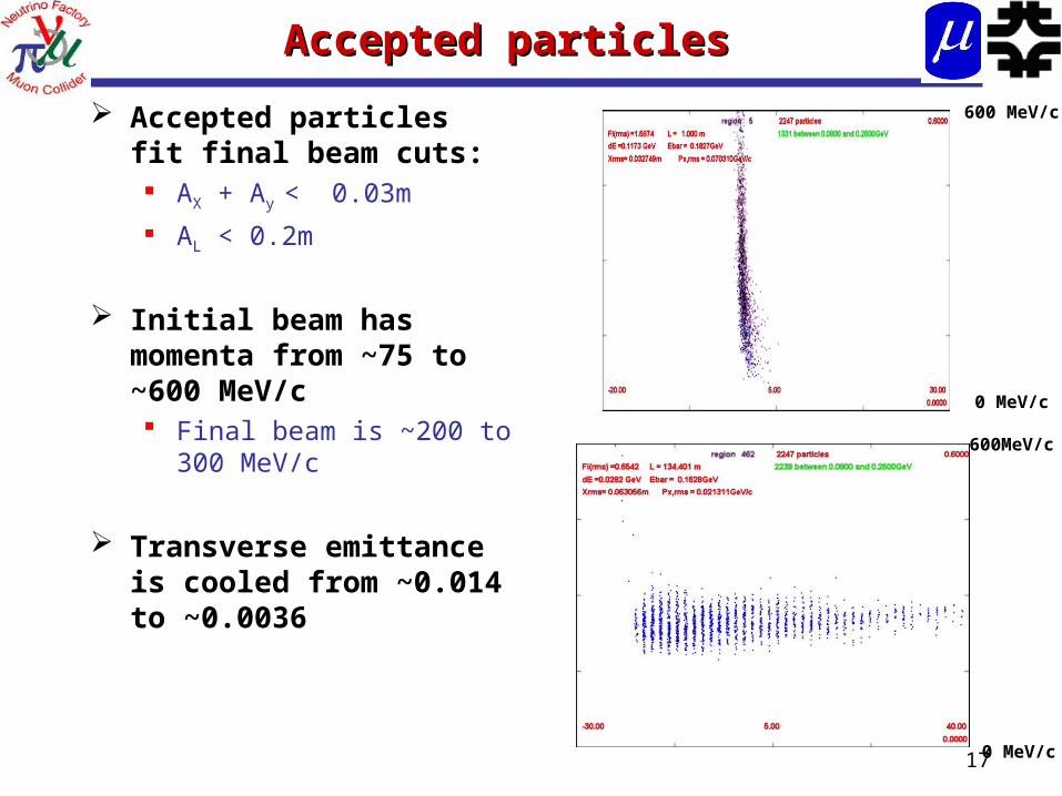
Accepted particlesAccepted particles
Accepted particles fit final beam cuts: AX + Ay < 0.03m
AL < 0.2m
Initial beam has momenta from ~75 to ~600 MeV/c Final beam is ~200 to
300 MeV/c
Transverse emittance is cooled from ~0.014 to ~0.0036
600 MeV/c
600MeV/c
0 MeV/c
0 MeV/c
18
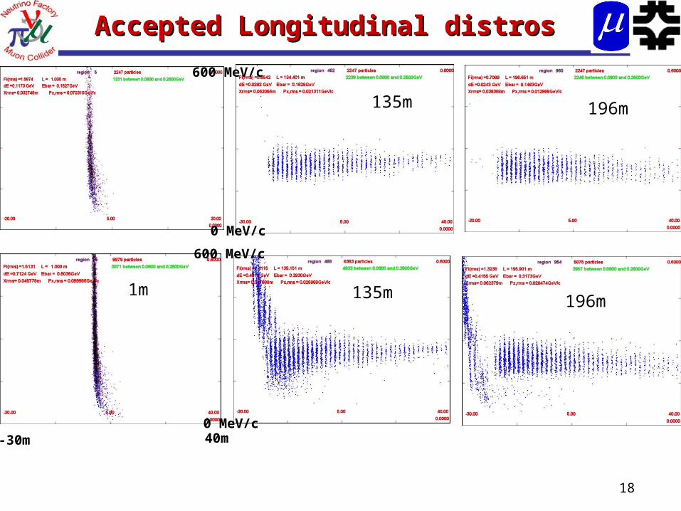
Accepted Longitudinal distrosAccepted Longitudinal distros
1m 135m
135m 196m
196m
-30m 40m
600 MeV/c
600 MeV/c
0 MeV/c
0 MeV/c
19
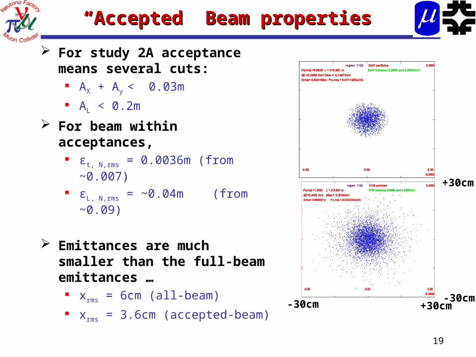
““Accepted” Beam propertiesAccepted” Beam properties
For study 2A acceptance means several cuts: AX + Ay < 0.03m
AL < 0.2m
For beam within acceptances, εt, N,rms = 0.0036m (from
~0.007) εL, N,rms = ~0.04m (from
~0.09)
Emittances are much smaller than the full-beam emittances … xrms = 6cm (all-beam)
xrms = 3.6cm (accepted-beam)-30cm +30cm
-30cm
+30cm
20
Variations - focusing Variations - focusing
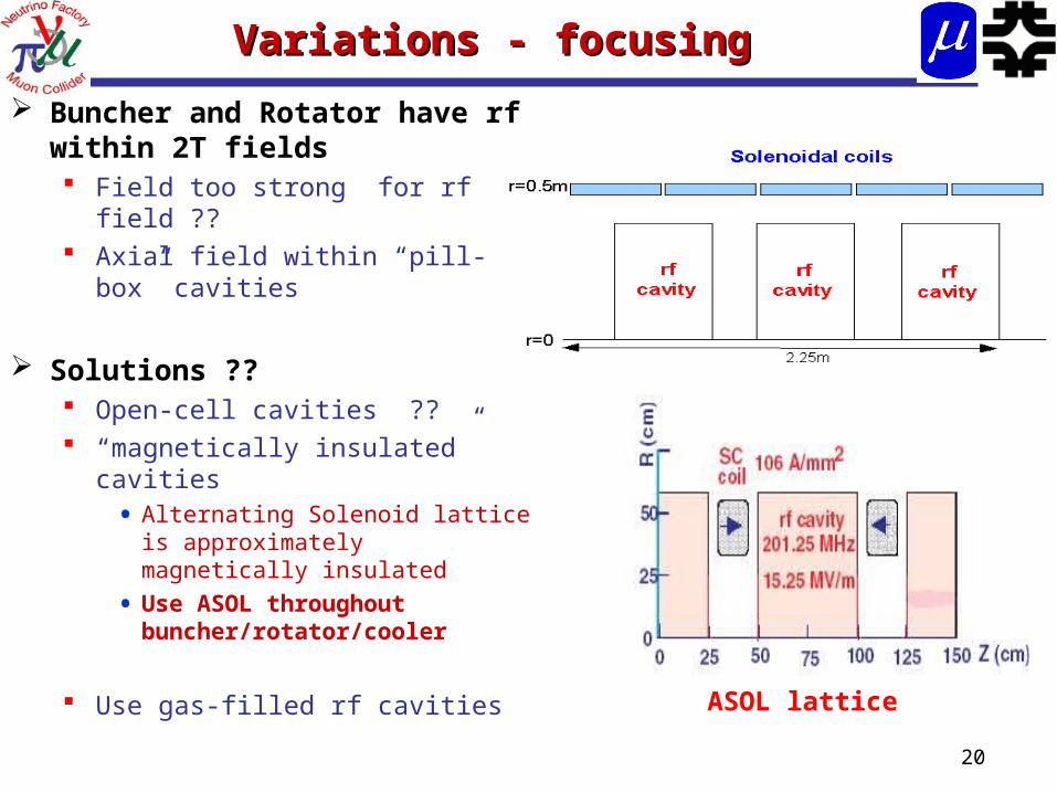
Buncher and Rotator have rf within 2T fields Field too strong for rf field ?? Axial field within “pill-box”
cavities
Solutions ?? Open-cell cavities ?? “magnetically insulated”
cavities• Alternating Solenoid lattice is
approximately magnetically insulated
• Use ASOL throughout buncher/rotator/cooler
Use gas-filled rf cavitiesASOL lattice
21
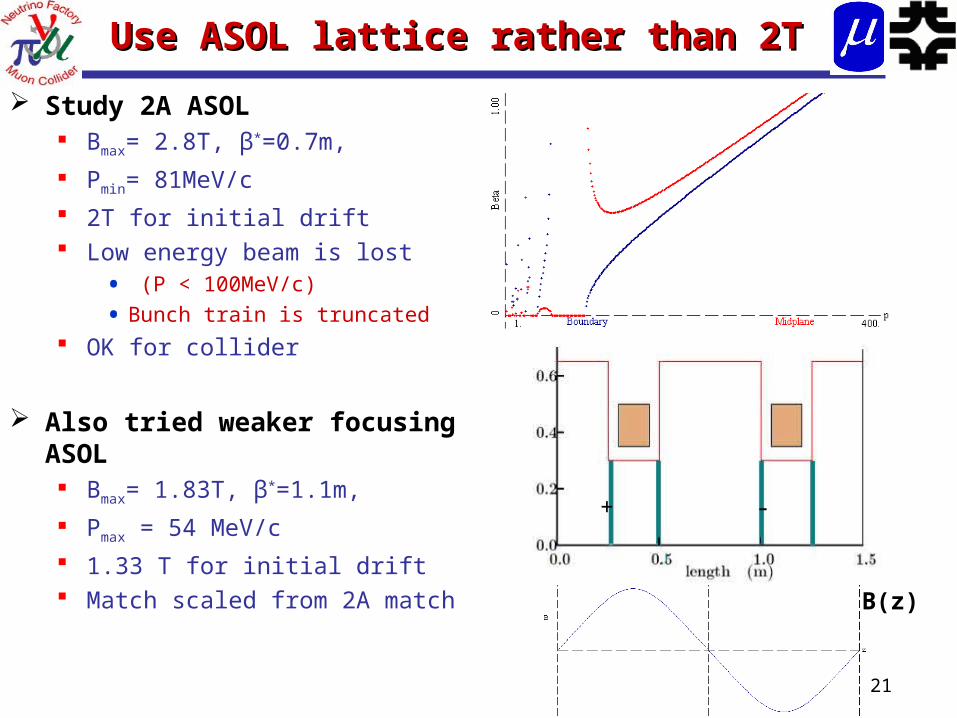
Use ASOL lattice rather than 2TUse ASOL lattice rather than 2T
Study 2A ASOL Bmax= 2.8T, β*=0.7m,
Pmin= 81MeV/c 2T for initial drift Low energy beam is lost
• (P < 100MeV/c)
• Bunch train is truncated OK for collider
Also tried weaker focusing ASOL Bmax= 1.83T, β*=1.1m,
Pmax = 54 MeV/c 1.33 T for initial drift Match scaled from 2A match
+ -
B(z)
22
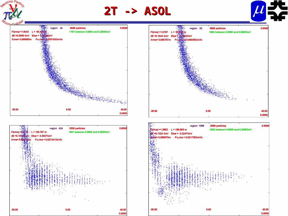
2T -> ASOL2T -> ASOL
23
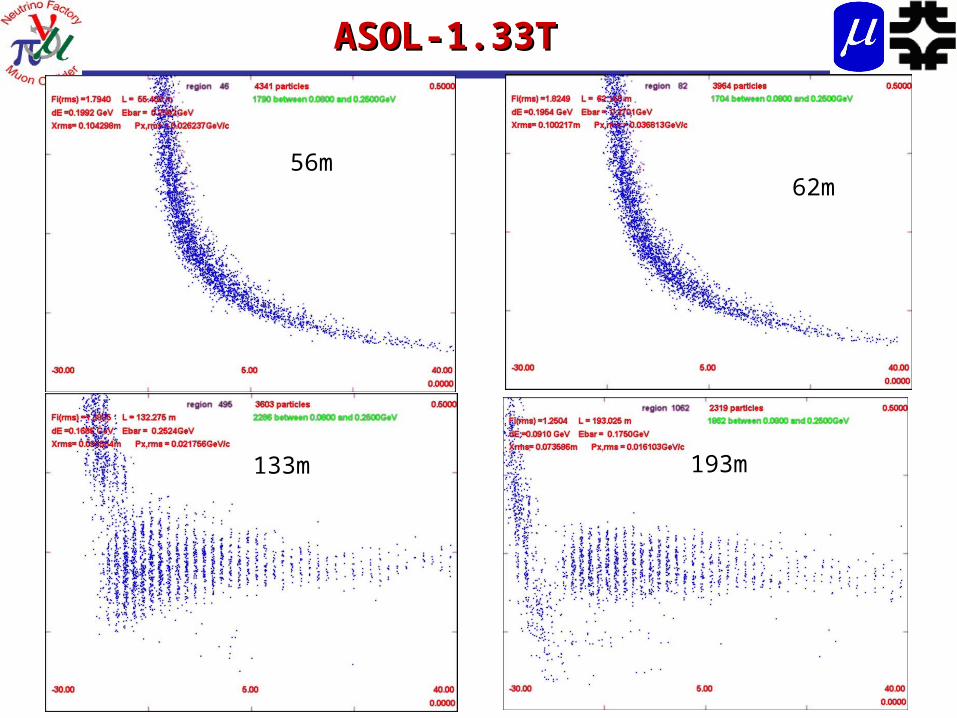
ASOL-1.33T ASOL-1.33T
56m62m
133m 193m
24
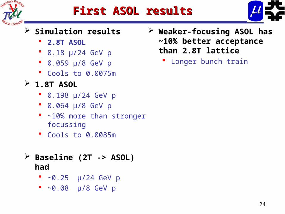
First ASOL results First ASOL results
Simulation results 2.8T ASOL 0.18 μ/24 GeV p 0.059 μ/8 GeV p Cools to 0.0075m
1.8T ASOL 0.198 μ/24 GeV p 0.064 μ/8 GeV p ~10% more than stronger
focussing Cools to 0.0085m
Baseline (2T -> ASOL) had ~0.25 μ/24 GeV p ~0.08 μ/8 GeV p
Weaker-focusing ASOL has ~10% better acceptance than 2.8T lattice Longer bunch train
25
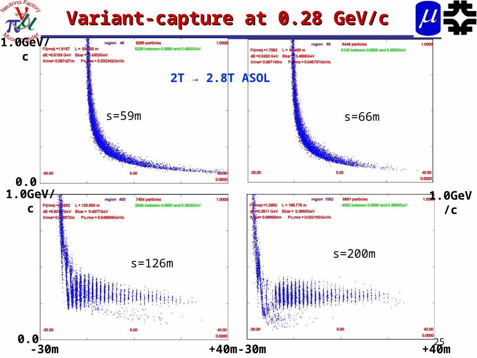
Variant-capture at 0.28 GeV/cVariant-capture at 0.28 GeV/c
0.0
1.0GeV/c
1.0GeV/c
0.0
2T → 2.8T ASOL
-30m +40m -30m +40m
1.0GeV/c
s=59m s=66m
s=126ms=200m
26
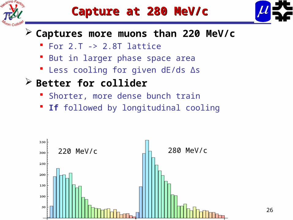
Capture at 280 MeV/cCapture at 280 MeV/c
Captures more muons than 220 MeV/c For 2.T -> 2.8T lattice But in larger phase space area Less cooling for given dE/ds Δs
Better for collider Shorter, more dense bunch train If followed by longitudinal cooling
220 MeV/c 280 MeV/c
27
Higher-Energy Simulation resultsHigher-Energy Simulation results
Higher energy capture improves capture for high-field lattice Cooling is slower
Not as good for low-field lattice Weaker focusing reduces
cooling
For High field lattice: 2.8T ASOL
8GeV beam 0.065 μ/p in εt <0.03, εL <0.2
0.093 μ/p in εt <0.045, εL <0.3
24 GeV beam 0.19 μ/p in εt <0.03, εL <0.2
0.26 μ/p in εt <0.045, εL <0.3
For Low-field lattice• 1.8T ASOL
8GeV beam
• 0.053 μ/p in εt <0.03, εL <0.2
• 0.083 μ/p in εt <0.045, εL <0.3
• cools only to ~0.010m
28
DiscussionDiscussion
High frequency phase-energy rotation + cooling has been explored
Shorter system better for Collider Shorter bunch train; denser bunches
“magnetic insulated” lattice could be used rather than B = 2 or 1.75 T lattice Slightly worse performance (?)
•~10 to 20% worse for neutrino factory Ok for Collider
•Particles lost are at end of bunch train

29
Any Questions?Any Questions?

30
Project X Status Project X Status
31
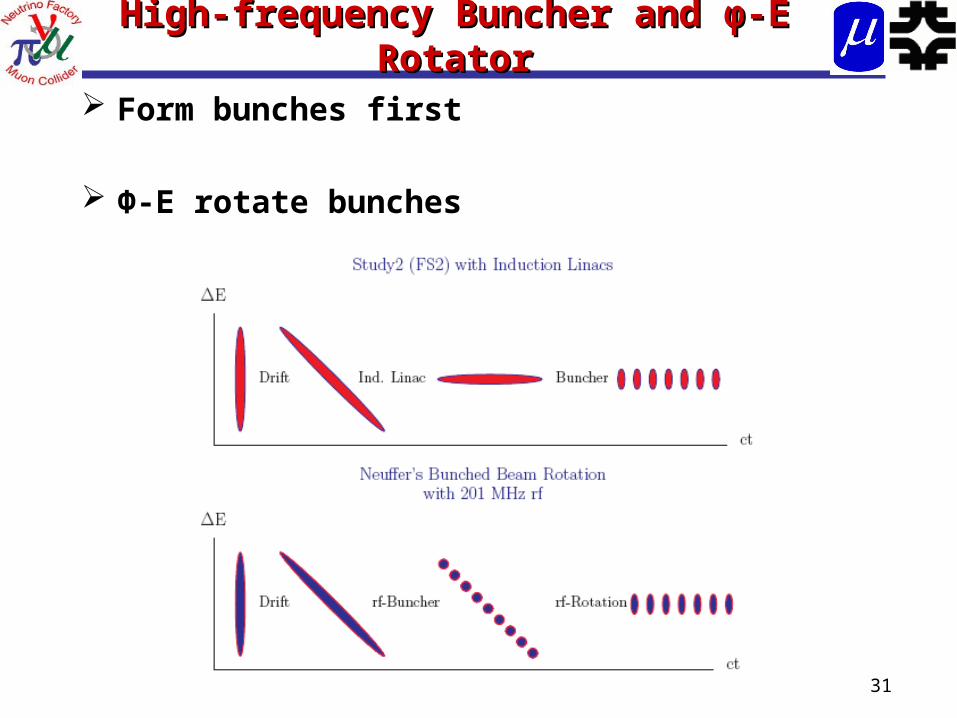
High-frequency Buncher and High-frequency Buncher and φφ-E -E RotatorRotator
Form bunches first
Φ-E rotate bunches