1- Consider a coaxial cable with characteristic impedance Z 0 Ω …eem.eskisehir.edu.tr/cozzaim/EEM...
46
1- Consider a coaxial cable with characteristic impedance Z 0 = 75.0 Ω and solid plastic insulator with ε r = 4.0 and α=0.01904 N/m as shown in the figure. Consider f = 250 MHz. a) Find the wavelength, the load and the input reflection coefficient and the input impedance. b) Find the phasor voltage and current and average power at the input of the cable line. c) Find the average power delivered to the load. 2 2 0 1 2 2 2 1 150 75 1 a) 0.6 m, 0.2111 115.13 150 75 3 1 b) 42.81 V 371.87 mA Re 7.96 W 0 0 0.6332 c) 0.6332 0 0 l jl in R in R in in r g in in g in in in in g in g in l l c e e Z Z f V Z V V I P VI Z Z Z Z e S e α β γ γ λ ε − − ∗ − − +Γ − = = Γ = = →Γ =Γ = → = = Ω + −Γ = = → = = → = = + + = = L W 2 2 2 21 0 2 2 2 0 21 1 4.689 2 1 1 L G S L S in S V Z P Z Z S −Γ → = = + − Γ −Γ Γ
Transcript of 1- Consider a coaxial cable with characteristic impedance Z 0 Ω …eem.eskisehir.edu.tr/cozzaim/EEM...
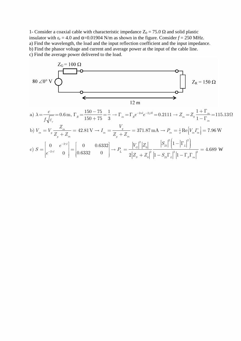
1- Consider a coaxial cable with characteristic impedance Z0 = 75.0 Ω and solid plastic insulator with εr = 4.0 and α=0.01904 N/m as shown in the figure. Consider f = 250 MHz. a) Find the wavelength, the load and the input reflection coefficient and the input impedance. b) Find the phasor voltage and current and average power at the input of the cable line. c) Find the average power delivered to the load.
2 2
0
12
2
2
1150 75 1a) 0.6m, 0.2111 115.13
150 75 3 1
b) 42.81V 371.87 mA Re 7.96W
0 0 0.6332c)
0.6332 00
l j l in
R in R in
inr
gin
in g in in in in
g in g in
l
l
ce e Z Z
f
VZV V I P V I
Z Z Z Z
eS
e
α β
γ
γ
λε
− −
∗
−
−
+ Γ−= = Γ = = → Γ =Γ = → = = Ω
+ −Γ
= = → = = → = = + +
= =
LW
2 22
210
2 2 2
0 21
14.689
2 1 1
LG
S L S in
SV ZP
Z Z S
− Γ → = = + − Γ −Γ Γ
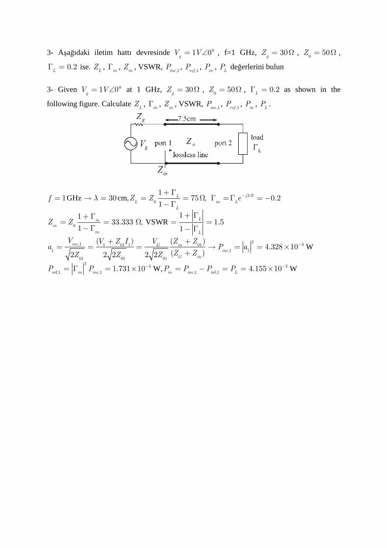
3- Aşağıdaki iletim hattı devresinde 1 0g
V V= ∠ ° , f=1 GHz, 30gZ = Ω ,
050Z = Ω ,
0.2LΓ = ise.
LZ ,
inΓ ,
inZ , VSWR,
,1incP ,
,1refP ,
inP ,
LP değerlerini bulun
3- Given 1 0
gV V= ∠ ° at 1 GHz, 30
gZ = Ω ,
050Z = Ω , 0.2
LΓ = as shown in the
following figure. Calculate LZ ,
inΓ ,
inZ , VSWR,
,1incP ,
,1refP ,
inP ,
LP .
GHz cm
VSWR
W
W,
2
0
0
2,1 31 01 1 011 ,1 1
01 01 012
4
ref,1 ,1
11 30 , 75 , 0.2
1
1133.333 , 1.5
1 1
( ) ( )4.328 10
( )2 2 2 2 2
1.731 10
j lL
L in L
L
Lin
in
in L
inc G in
inc
G in
in inc i
f Z Z e
Z Z
V V Z I V Z Za P a
Z ZZ Z Z
P P P
βλ −
−
−
+ Γ= → = = = Ω Γ =Γ = −
−Γ
+ Γ+ Γ= = Ω = =
−Γ − Γ
+ += = = → = = ×
+
= Γ = × W3
,1 ref,14.155 10
n inc LP P P −= − = = ×
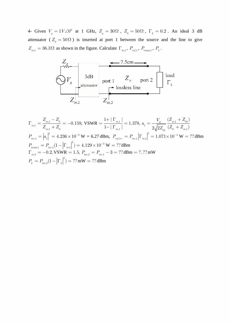
4- Given 1 0g
V V= ∠ ° at 1 GHz, 30gZ = Ω ,
050Z = Ω , 0.2
LΓ = . An ideal 3 dB
attenuator (0
50Z = Ω ) is inserted at port 1 between the source and the line to give
,136.3
inZ = Ω as shown in the figure. Calculate
,1inΓ ,
,1refP ,
trans,1P ,
LP .
VSWR
W = 6.27 dBm, W dBm
W
,1 0 ,1 ,1 01
,1 1
,1 0 ,1 ,10122
3 4
,1 1 ,1 ,1 ,1
23
trans,1 ,1 ,1
1 | | ( )0.159, 1.378,
1 | | ( )2 2
4.236 10 1.071 10 ??
(1 ) 4.129 10 ?
in in inG
in
in in G in
inc ref inc in
inc in
Z Z Z ZVa
Z Z Z ZZ
P a P P
P P
− −
=
−
− + Γ +Γ = = − = = =
+ − Γ +
= = × = Γ = × =
= − Γ = × = dBm
VSWR dBm mW
mW dBm
,2 inc,2 ,1
2
inc,2
?
0.2, 1.5, 3 ?? ?.??
(1 ) ?? ??
in inc
L L
P P
P P
Γ = − = = − = =
= − Γ = =
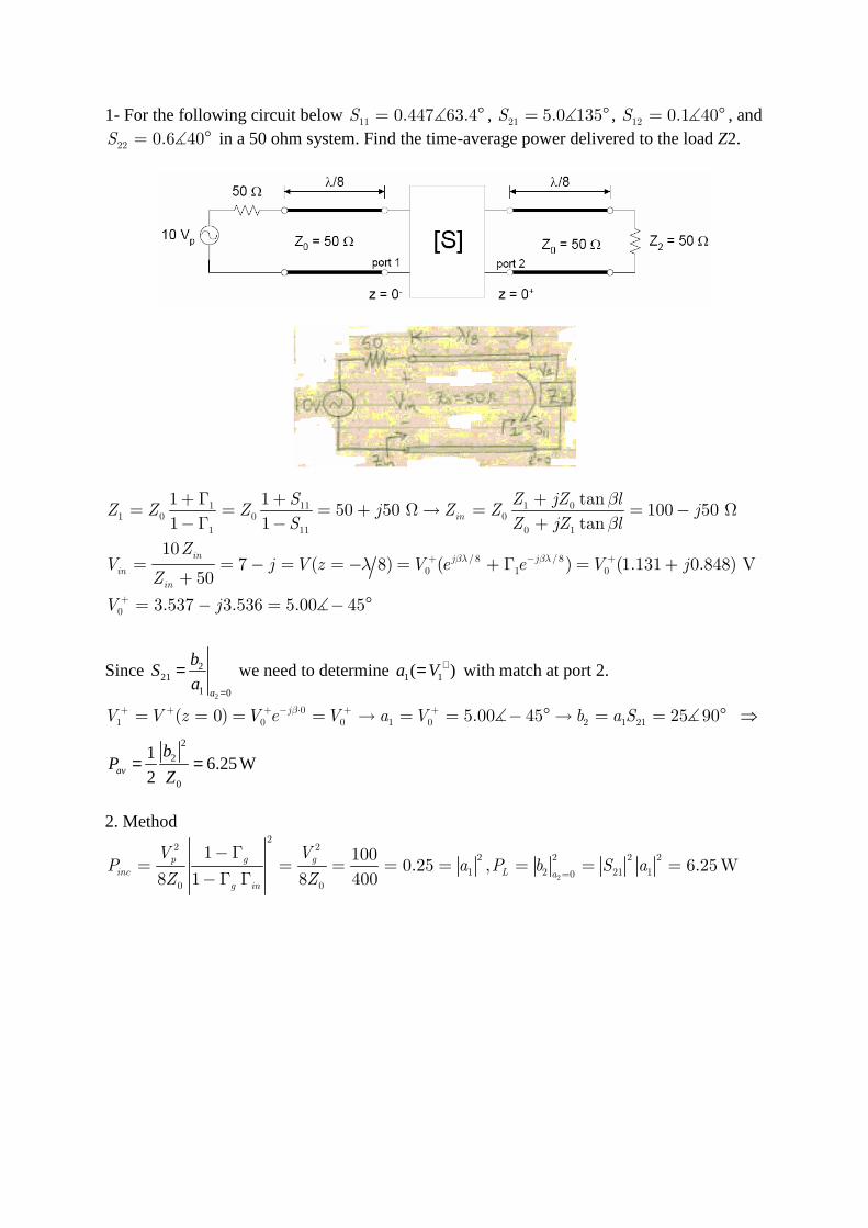
1- For the following circuit below 11 0.447 63.4S = °∡ , 21 5.0 135S = °∡ , 12 0.1 40S = °∡ , and
22 0.6 40S = °∡ in a 50 ohm system. Find the time-average power delivered to the load Z2.
1 11 1 01 0 0 0
1 11 0 1
/8 /80 1 0
0
1 1 tan50 50 100 50
1 1 tan
107 ( 8) ( ) (1.131 0.848) V
50
3.537 3.536 5.00 45
in
in j j
in
in
S Z jZ lZ Z Z j Z Z j
S Z jZ l
ZV j V z V e e V j
Z
V j
βλ βλ
β
β
λ + − +
+
+ Γ + += = = + Ω→ = = − Ω
−Γ − +
= = − = = − = + Γ = ++
= − = − °∡
Since 2
221
1 0a
bS
a=
= we need to determine 1 1( )a V += with match at port 2.
01 0 0 1 0 2 1 21( 0) 5.00 45 25 90jV V z V e V a V b a Sβ+ + + − ⋅ + += = = = → = = − ° → = = °∡ ∡ ⇒
2
2
0
16.25W
2av
bP
Z= =
2. Method
2
22 2
2 2 2 2
1 2 21 100 0
1 1000.25 , 6.25W
8 1 8 400
p g g
inc L ag in
V VP a P b S a
Z Z =
−Γ= = = = = = = =
−Γ Γ
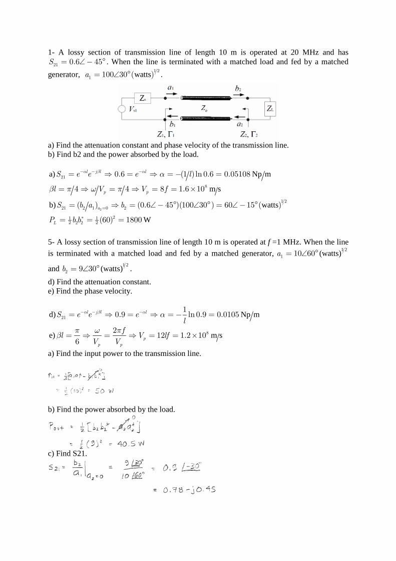
1- A lossy section of transmission line of length 10 m is operated at 20 MHz and has
21 0.6 45S = ∠− ° . When the line is terminated with a matched load and fed by a matched
generator, watts1 2
1 100 30 ( )a = ∠ ° .
a) Find the attenuation constant and phase velocity of the transmission line. b) Find b2 and the power absorbed by the load. a) Np m
m s
b) watts
W
2
21
8
1 2
21 2 1 0 2
21 12 22 2
0.6 (1 )ln 0.6 0.05108
4 4 8 1.6 10
( ) (0.6 45 )(100 30 ) 60 15 ( )
(60) 1800
l j l l
p p
a
L
S e e e l
l V V f
S b a b
P b b
α β α α
β π ω π
− − −
=
∗
= ⇒ = ⇒ =− =
= ⇒ = ⇒ = = ×
= ⇒ = ∠− ° ∠ ° = ∠− °
= = =
5- A lossy section of transmission line of length 10 m is operated at f =1 MHz. When the line
is terminated with a matched load and fed by a matched generator, 1 2
(watts)1 10 60a = ∠ °
and 1 2
(watts)2 9 30b = ∠ ° .
d) Find the attenuation constant. e) Find the phase velocity.
d) Np m
e) m s
21
8
10.9 ln 0.9 0.0105
212 1.2 10
6
l j l l
p
p p
S e e el
fl V lf
V V
α β α α
π ω πβ
− − −= ⇒ = ⇒ =− =
= ⇒ = ⇒ = = ×
a) Find the input power to the transmission line.
b) Find the power absorbed by the load.
c) Find S21.
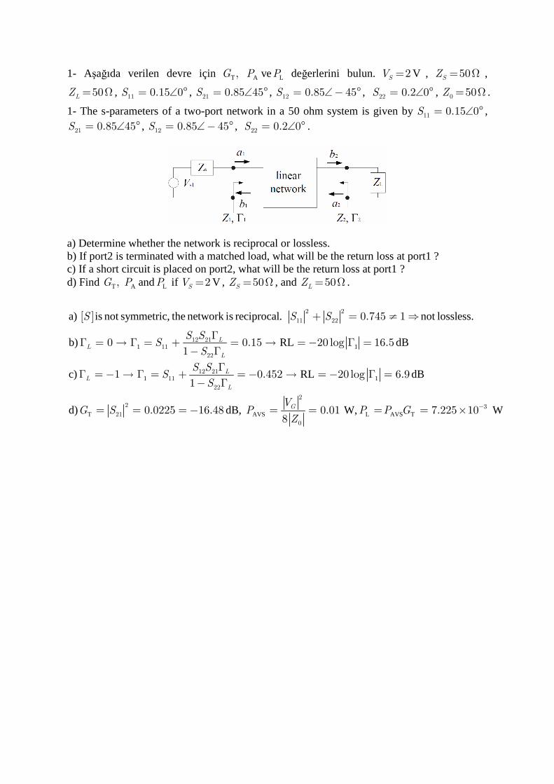
1- Aşağıda verilen devre için T,G A LveP P değerlerini bulun. V2SV = , 50SZ = Ω ,
50LZ = Ω , 11 0.15 0S = ∠ ° , 21 0.85 45S = ∠ ° , 12 0.85 45S = ∠− ° , 22 0.2 0S = ∠ ° , 0 50Z = Ω .
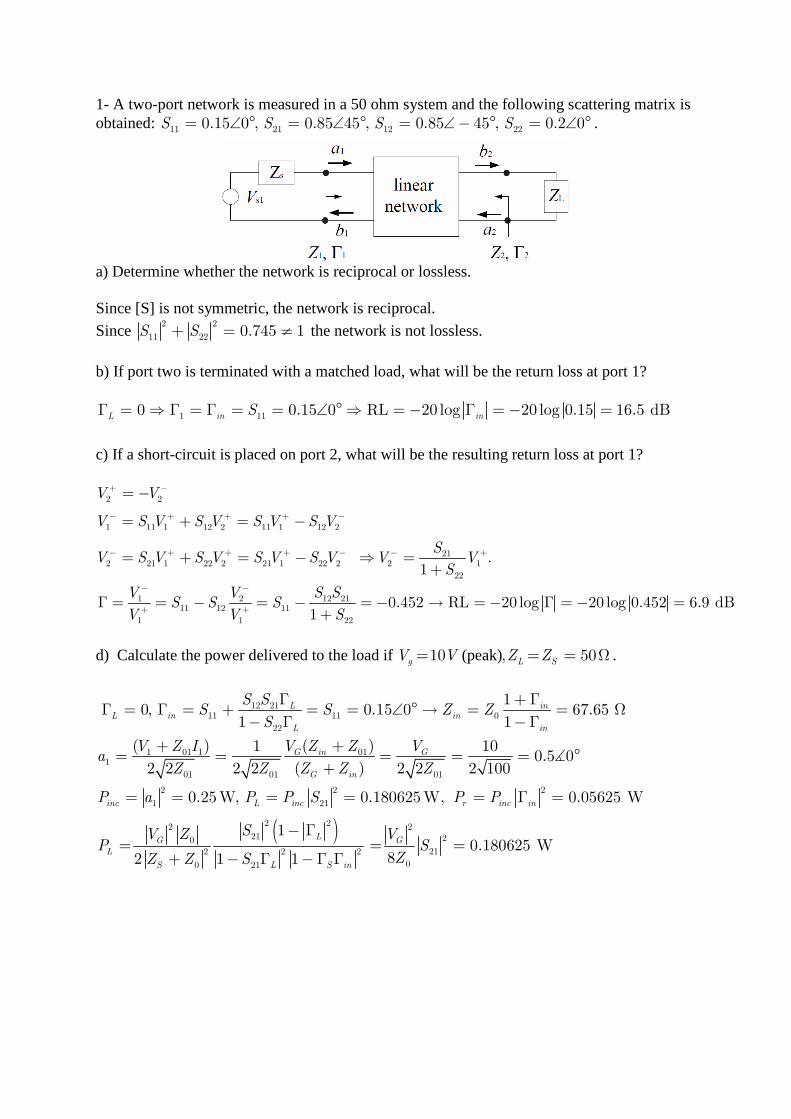
1- The s-parameters of a two-port network in a 50 ohm system is given by 11 0.15 0S = ∠ ° ,
21 0.85 45S = ∠ ° , 12 0.85 45S = ∠− ° , 22 0.2 0S = ∠ ° .
a) Determine whether the network is reciprocal or lossless. b) If port2 is terminated with a matched load, what will be the return loss at port1 ? c) If a short circuit is placed on port2, what will be the return loss at port1 ? d) Find T,G A LandP P if V2SV = , 50SZ = Ω , and 50LZ = Ω .
[ ]
1 1
1 1
T
a) is not symmetric, the network is reciprocal. not lossless.
b) RL dB
c) RL dB
d)
2 2
11 22
12 2111
22
12 2111
22
2
21
0.745 1
0 0.15 20 log 16.51
1 0.452 20 log 6.91
0.0225 1
LL
L
LL
L
S S S
S SS
S
S SS
S
G S
+ = ≠ ⇒
ΓΓ = → Γ = + = → =− Γ =
− Γ
ΓΓ = − → Γ = + = − → = − Γ =
− Γ
= = = − AVS L AVS TdB, W, W2
3
0
6.48 0.01 7.225 108GVP P P GZ
−= = = = ×
3- An amplifier circuit below is connected to a source with V2SV = and 25SZ = Ω , and its
output is connected to a load of 100LZ = Ω . (a) Find P A T TUand, , ,G G G G (b) Find A LandP P .
The s-parameters of the two port in 50 ohm are given by 11 0.61 170S = ∠− ° ,
21 2.3 80S = ∠ ° , 12 0.06 70S = ∠ ° , 22 0.72 25S = ∠− ° .
in out
LP
in
AVNA
AVS
V,
dB
0 0
0 0
12 21 12 2111 22
22 11
22
212 2
22
2
2 25 , 100 , 0.33, 0.33,
0.65 173.72, 0.76 25.0131 1
1113.18 11.2
1 1
1
1
S L
S L
Z Z Z Z
Z Z Z ZS S L S L
L S
L S
L
in L
S
V Z Z
S S S SS S
S S
PG S
P S
PG
P
− −+ += = Ω = Ω Γ = = − Γ = =
Γ ΓΓ = + = ∠− Γ = + = ∠−
− Γ − Γ
− Γ= = = =
− Γ − Γ
− Γ= =
−
in S
LT
AVS
TU T
AVS in
dB
dB
dB12
2
212 2
11
2 2 2 22 2
21 212 2 2 2
22 11
2 22
212 20
22
2
02
0
118.4 12.6
1
1 1 1 110.8 10.3
1 1 1 1
1 110.4 10.2
1 1
1
2 1
S out
S L S L
in S L S out L
S L
S
in S L
G
S
SS
PG S S
P S S
G G SS
V ZP P
Z Z∗
=
Γ =Γ
= =Γ − Γ
− Γ − Γ − Γ − Γ= = = = =
−Γ Γ − Γ − Γ −Γ Γ
− Γ − Γ= = = =
−Γ Γ − Γ
= =+ − Γ
( )L AVS T
W
W
2
2 22210
2 2 2
0 21
0.02
10.216
2 1 1
S
LG
S L S in
SV ZP P G
Z Z S
=
− Γ= = =
+ − Γ −Γ Γ
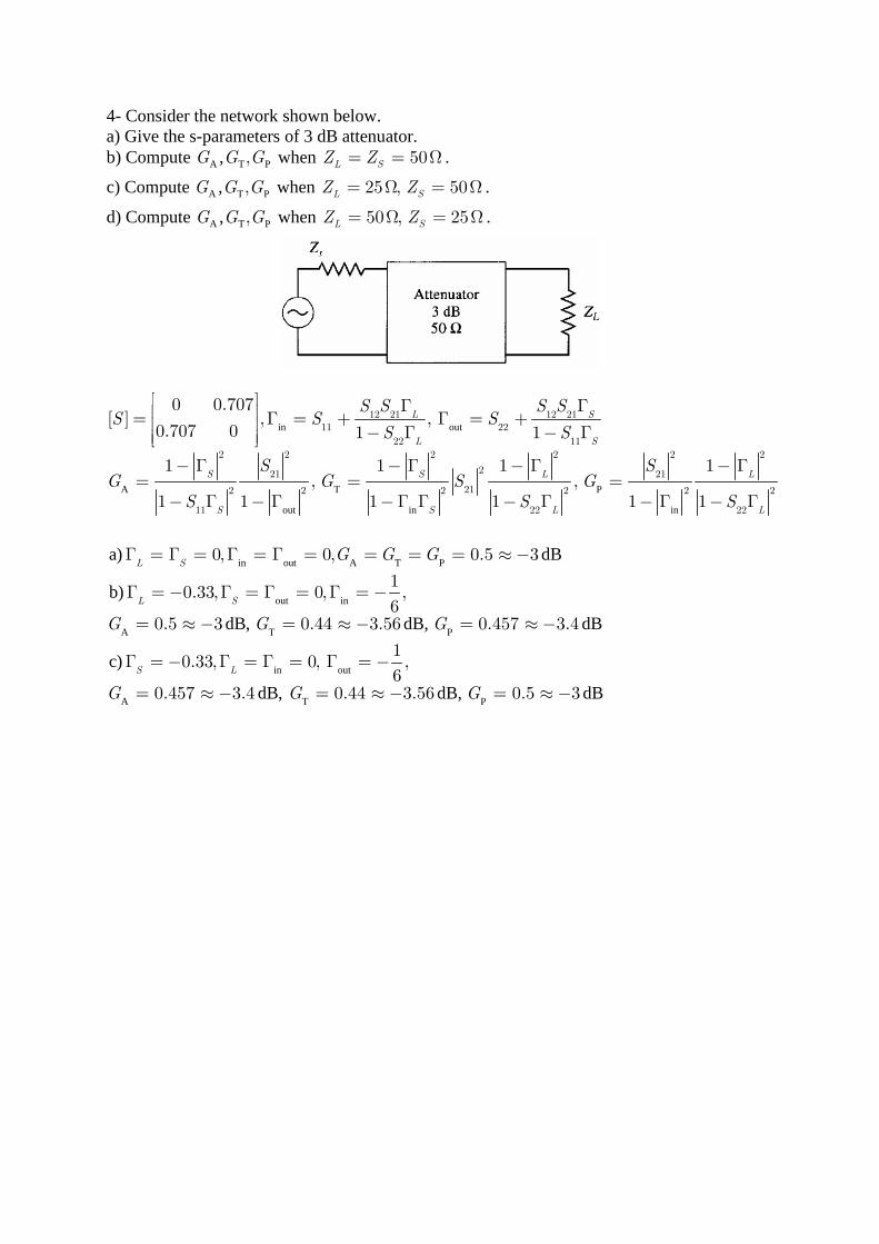
4- Consider the network shown below. a) Give the s-parameters of 3 dB attenuator. b) Compute A T P, ,G G G when 50L SZ Z= = Ω .
c) Compute A T P, ,G G G when 25 , 50L SZ Z= Ω = Ω .
d) Compute A T P, ,G G G when 50 , 25L SZ Z= Ω = Ω .
in out
A T P
out in in
in out A T Pa) d
12 21 12 2111 22
22 11
2 2 2 2 2 2
221 21
212 2 2 2 2 2
11 22 22
0 0.707[ ] , ,
0.707 0 1 1
1 1 1 1, ,
1 1 1 1 1 1
0, 0, 0.5 3
L S
L S
S S L L
S S L L
L S
S S S SS S S
S S
S SG G S G
S S S
G G G
Γ Γ = Γ = + Γ = + − Γ − Γ
− Γ − Γ − Γ − Γ= = =
− Γ − Γ −Γ Γ − Γ − Γ − Γ
Γ = Γ = Γ = Γ = = = = ≈−
out in
A T P
in out
A T P
B
b)
dB, dB, dB
c)
dB, dB, dB
10.33, 0, ,
60.5 3 0.44 3.56 0.457 3.4
10.33, 0, ,
60.457 3.4 0.44 3.56 0.5 3
L S
S L
G G G
G G G
Γ = − Γ = Γ = Γ = −
= ≈ − = ≈ − = ≈−
Γ = − Γ = Γ = Γ = −
= ≈ − = ≈ − = ≈−
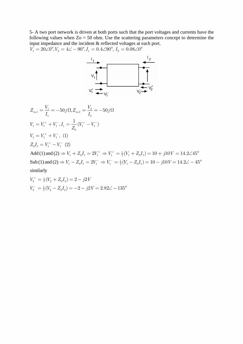
5- A two port network is driven at both ports such that the port voltages and currents have the following values when Zo = 50 ohm. Use the scattering parameters concept to determine the input impedance and the incident & reflected voltages at each port.
1 2 1 220 0 , 4 90 , 0.4 90 , 0.08 0V V I I= ∠ ° = ∠− ° = ∠ ° = ∠ °
Add (1) and (2)
Sub (1) and (2)
1 2,1 ,2
1 2
1 1 1 1 1 1
0
1 1 1
0 1 1 1
121 0 1 1 1 1 0 1
121 0 1 1 1 1 0 1
50 , 50
1, ( )
, (1)
(2)
2 ( ) 10 10 14.2 45
2 ( ) 10 10 14.2
in in
V VZ j Z j
I I
V V V I V VZ
V V V
Z I V V
V Z I V V V Z I j V
V Z I V V V Z I j V
+ − + −
+ −
+ −
+ +
− −
= =− Ω = =− Ω
= + = −
= +
= −
⇒ + = ⇒ = + = + = ∠ °
⇒ − = ⇒ = − = − =
similarly
122 2 0 2
122 2 0 2
45
( ) 2 2
( ) 2 2 2.82 135
V V Z I j V
V V Z I j V
+
−
∠− °
= + = −
= − =− − = ∠− °
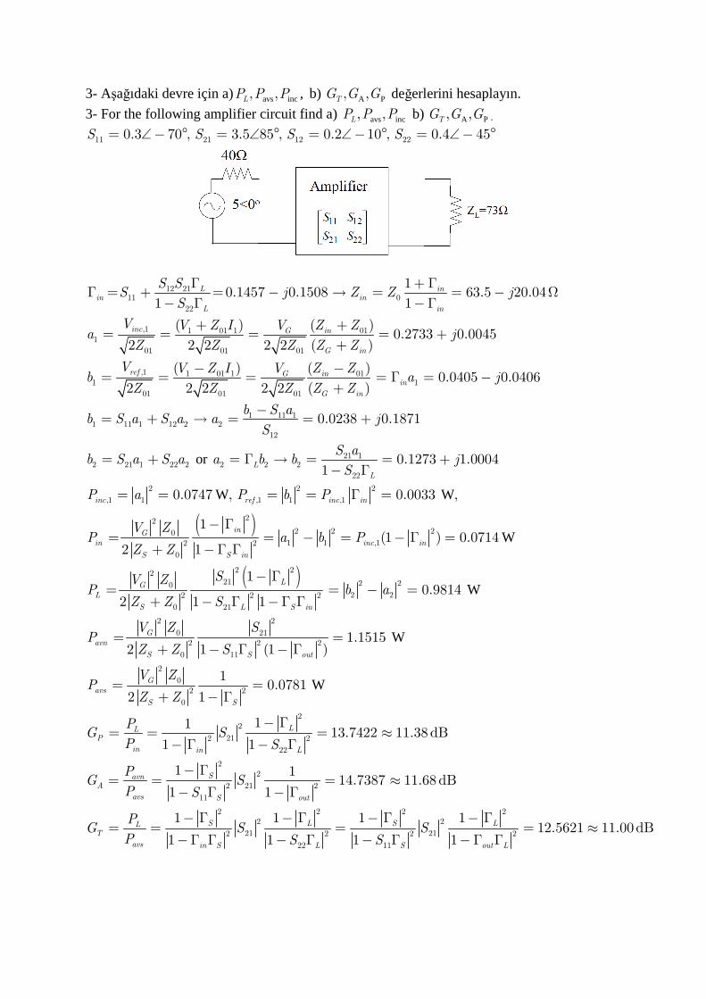
3- Aşağıdaki devre için a) avs inc, ,LP P P , b) A P, ,TG G G değerlerini hesaplayın.
3- For the following amplifier circuit find a) avs inc, ,LP P P b) A P, ,TG G G .
11 21 12 220.3 70 , 3.5 85 , 0.2 10 , 0.4 45S S S S= ∠− ° = ∠ ° = ∠− ° = ∠− °
12 2111 0
22
,1 1 01 1 011
01 01 01
,1 1 01 1 011 1
01 01 01
10.1457 0.1508 63.5 20.04
1 1
( ) ( )0.2733 0.0045
2 2 2 2 2 ( )
( ) ( )0.
2 2 2 2 2 ( )
L inin in
L in
inc G in
G in
ref G inin
G in
S SS j Z Z j
S
V V Z I V Z Za j
Z Z Z Z Z
V V Z I V Z Zb a
Z Z Z Z Z
Γ + ΓΓ = + = − → = = − Ω
− Γ −Γ
+ += = = = +
+
− −= = = = Γ =
+
( )
or
W W
1 11 11 11 1 12 2 2
12
21 12 21 1 22 2 2 2 2
22
2 2 2
,1 1 ,1 1 ,1
222 20
1 12 2
0
0405 0.0406
0.0238 0.1871
0.1273 1.00041
0.0747 , 0.0033 ,
1
2 1
L
L
inc ref inc in
inG
in i
S S in
j
b S ab S a S a a j
S
S ab S a S a a b b j
S
P a P b P
V ZP a b P
Z Z
−
−= + → = = +
= + = Γ → = = +− Γ
= = = = Γ =
− Γ= = − =
+ −Γ Γ
( )
W
W
W
W
2
,1
2 2221 2 20
2 22 2 2
0 21
2 2
0 212 2 2
0 11
2
02 2
0
22
212 2
22
(1 ) 0.0714
10.9814
2 1 1
1.15152 1 (1 )
10.0781
2 1
1113.7422 11.38
1 1
nc in
LG
L
S L S in
G
avn
S S out
G
avs
S S
LLP
in in L
SV ZP b a
Z Z S
V Z SP
Z Z S
V ZP
Z Z
PG S
P S
− Γ =
− Γ= = − =
+ − Γ −Γ Γ
= =+ − Γ − Γ
= =+ − Γ
− Γ= = = ≈
− Γ − Γ2
2
212 2
11
2 2 2 22 2
21 212 2 2 2
22 11
dB
1 114.7387 11.68dB
1 1
1 1 1 112.5621 11.00dB
1 1 1 1
SavnA
avs S out
S L S LLT
avs in S L S out L
PG S
P S
PG S S
P S S
− Γ= = = ≈
− Γ − Γ
− Γ − Γ − Γ − Γ= = = = ≈
−Γ Γ − Γ − Γ −Γ Γ
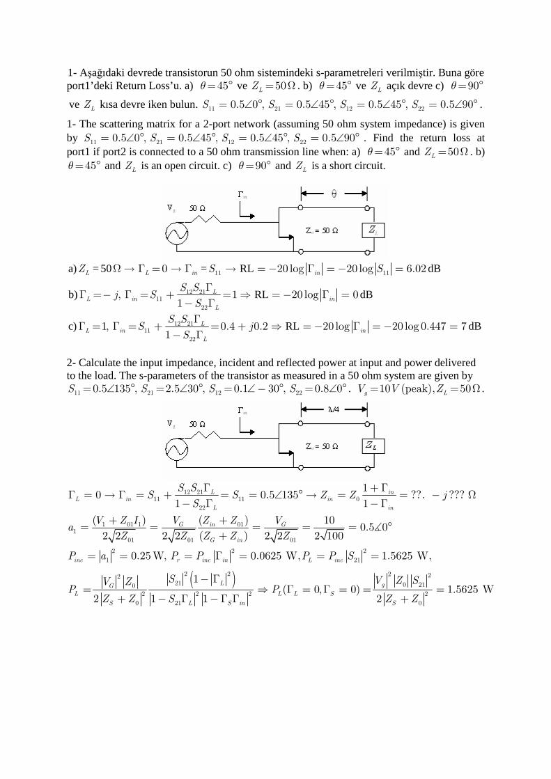
1- Aşağıdaki devrede transistorun 50 ohm sistemindeki s-parametreleri verilmiştir. Buna göre port1’deki Return Loss’u. a) = °45θ ve = Ω50LZ . b) = °45θ ve LZ açık devre c) = °90θ
ve LZ kısa devre iken bulun. = ∠ ° = ∠ ° = ∠ ° = ∠ °11 21 12 220.5 0 , 0.5 45 , 0.5 45 , 0.5 90S S S S .
1- The scattering matrix for a 2-port network (assuming 50 ohm system impedance) is given by = ∠ ° = ∠ ° = ∠ ° = ∠ °11 21 12 220.5 0 , 0.5 45 , 0.5 45 , 0.5 90S S S S . Find the return loss at port1 if port2 is connected to a 50 ohm transmission line when: a) = °45θ and = Ω50LZ . b) = °45θ and LZ is an open circuit. c) = °90θ and LZ is a short circuit.
a) = 50 = RL dB
b) RL dB
c) RL dB
11 11
12 2111
22
12 2111
22
0 20 log 20 log 6.02
, 1 20 log 01
1, 0.4 0.2 20 log 20 log 0.447 71
L L in in
LL in in
L
LL in in
L
Z S S
S Sj S
S
S SS j
S
Ω→ Γ = → Γ → =− Γ = − =
ΓΓ =− Γ = + = ⇒ =− Γ =
− Γ
ΓΓ = Γ = + = + ⇒ = − Γ = − =
− Γ
2- Calculate the input impedance, incident and reflected power at input and power delivered to the load. The s-parameters of the transistor as measured in a 50 ohm system are given by
11 21 12 220.5 135 , 2.5 30 , 0.1 30 , 0.8 0S S S S= ∠ ° = ∠ ° = ∠− ° = ∠ ° . 10 (peak), 50g LV V Z= = Ω .
12 21
11 11 0
22
1 01 1 011
01 01 01
2 2 2
1 21
2
0
10 0.5 135 ??. ???
1 1
( ) ( ) 100.5 0
2 2 2 2 ( ) 2 2 2 100
0.25W, 0.0625 W, 1.5625 W,
2
L inL in in
L in
G in G
G in
inc r inc in L inc
G
L
S
S SS S Z Z j
S
V Z I V Z Z Va
Z Z Z Z Z
P a P P P P S
V ZP
Z
Γ + ΓΓ = → Γ = + = = ∠ ° → = = − Ω
− Γ −Γ
+ += = = = = °
+
= = = Γ = = =
=
∡
( )2 2 2 221 0 21
2 2 2 2
0 21 0
1( 0, 0) 1.5625 W
1 1 2
L g
L L S
L S in S
S V Z SP
Z S Z Z
− Γ⇒ Γ = Γ = = =
+ − Γ −Γ Γ +
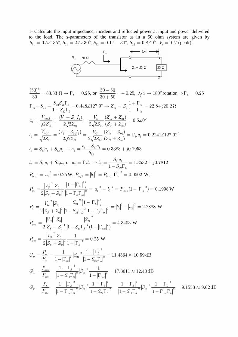
1- Calculate the input impedance, incident and reflected power at input and power delivered to the load. The s-parameters of the transistor as in a 50 ohm system are given by
11 21 12 220.5 135 , 2.5 30 , 0.1 30 , 0.8 0S S S S= ∠ ° = ∠ ° = ∠− ° = ∠ ° . 10 (peak)gV V= .
or rotation2
12 2111 0
22
,1 1 01 1 011
01 01 01
,1
1
(50) 30 5083.33 0.25, 0.25, 4 180 0.25
30 30 50
10.448 127.9 22.8+ 20.2
1 1
( ) ( )0.5 0
2 2 2 2 2 ( )
L L
L inin in
L in
inc G in
G in
ref
S SS Z Z j
S
V V Z I V Z Za
Z Z Z Z Z
Vb
λ−
= Ω→ Γ = =− → ° ⇒Γ =+
Γ + ΓΓ = + = ° → = = Ω
− Γ −Γ
+ += = = = °
+
=
∡
∡
or
W
1 01 1 011
01 01 01
1 11 11 11 1 12 2 2
12
21 12 21 1 22 2 2 2 2
22
2 2
,1 1 ,1 1 ,1
( ) ( )0.2241 127.92
2 2 2 2 2 ( )
0.3383 0.1953
1.3532 0.78121
0.25 ,
G inin
G in
L
L
inc ref inc i
V Z I V Z Za
Z Z Z Z Z
b S ab S a S a a j
S
S ab S a S a a b b j
S
P a P b P
− −= = = Γ = °
+
−= + → = = +
= + = Γ → = = +− Γ
= = = = Γ
∡
( )
( )
W
W
W
W
2
222 2 20
1 1 ,12 2
0
2 2221 2 20
2 22 2 2
0 21
2 2
0 212 2 2
0 11
2
02 2
0
0.0502 ,
1(1 ) 0.1998
2 1
12.2888
2 1 1
4.34032 1 (1 )
10.
2 1
n
inG
in inc in
S S in
LG
L
S L S in
G
avn
S S out
G
avs
S S
V ZP a b P
Z Z
SV ZP b a
Z Z S
V Z SP
Z Z S
V ZP
Z Z
=
− Γ= = − = − Γ =
+ −Γ Γ
− Γ= = − =
+ − Γ −Γ Γ
= =+ − Γ − Γ
= =+ − Γ
W
22
212 2
22
22
212 2
11
2 2 2 22 2
21 212 2 2 2
22 11
25
1111.4564 10.59dB
1 1
1 117.3611 12.40dB
1 1
1 1 1 19.1553 9.62dB
1 1 1 1
LLP
in in L
SavnA
avs S out
S L S LLT
avs in S L S out L
PG S
P S
PG S
P S
PG S S
P S S
− Γ= = = ≈
− Γ − Γ
− Γ= = = ≈
− Γ − Γ
− Γ − Γ − Γ − Γ= = = = ≈
−Γ Γ − Γ − Γ −Γ Γ
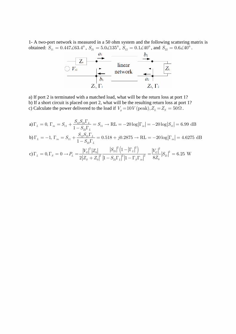
1- A two-port network is measured in a 50 ohm system and the following scattering matrix is obtained: 11 0.447 63.4S = °∡ , 21 5.0 135S = °∡ , 12 0.1 40S = °∡ , and 22 0.6 40S = °∡ .
a) If port 2 is terminated with a matched load, what will be the return loss at port 1? b) If a short circuit is placed on port 2, what will be the resulting return loss at port 1? c) Calculate the power delivered to the load if 10 (peak), 50g L SV V Z Z= = = Ω .
( )
a)
b)
c)
ΓΓ = Γ = + = → =− Γ = − =
− Γ
ΓΓ = − Γ = + = + → =− Γ =
− Γ
− ΓΓ = Γ = → = = =
+ − Γ −Γ Γ
12 2111 11 11
22
12 2111
22
2 22 221 20
212 2 2
00 21
0, RL 20 log 20 log 6.99 dB1
1, 0.518 0.2875 RL 20 log 4.6275 dB1
10, 0 6.25
82 1 1
LL in in
L
LL in in
L
LG G
L S L
S L S in
S SS S S
S
S SS j
S
SV Z VP S
ZZ Z SW
1- A two-port network is measured in a 50 ohm system and the following scattering matrix is obtained: 11 21 12 220.15 0 , 0.85 45 , 0.85 45 , 0.2 0S S S S= ∠ ° = ∠ ° = ∠− ° = ∠ ° .
a) Determine whether the network is reciprocal or lossless. Since [S] is not symmetric, the network is reciprocal.
Since 2 2
11 22 0.745 1S S+ = ≠ the network is not lossless.
b) If port two is terminated with a matched load, what will be the return loss at port 1?
1 110 0.15 0 RL 20 log 20 log 0.15 16.5 dBL in inSΓ = ⇒ Γ = Γ = = ∠ ° ⇒ =− Γ = − =
c) If a short-circuit is placed on port 2, what will be the resulting return loss at port 1?
2 2
1 11 1 12 2 11 1 12 2
212 21 1 22 2 21 1 22 2 2 1
22
1 2 12 2111 12 11
1 1 22
.1
0.452 RL 20 log 20 log 0.452 6.9 dB1
V V
V S V S V S V S V
SV S V S V S V S V V V
S
V V S SS S S
V V S
+ −
− + + + −
− + + + − − +
− −
+ +
= −
= + = −
= + = − ⇒ =+
Γ = = − = − = − → =− Γ = − =+
d) Calculate the power delivered to the load if (peak)= = = Ω10 , 50g L SV V Z Z .
Γ + Γ
Γ = Γ = + = = ∠ ° → = = Ω− Γ −Γ
+ += = = = = °
+
= = = = = Γ =
=+
∡
12 2111 11 0
22
1 01 1 011
01 01 01
2 2 2
1 21
2
0
10, 0.15 0 67.65
1 1
( ) 1 ( ) 100.5 0
2 2 2 2 ( ) 2 2 2 100
0.25W, 0.180625W, 0.05625 W
2
L inL in in
L in
G in G
G in
inc L inc r inc in
G
L
S
S SS S Z Z
S
V Z I V Z Z Va
Z Z Z Z Z
P a P P S P P
V ZP
Z Z
( )− Γ= =
− Γ −Γ Γ
2 2 221 2
212 2 2
00 21
10.180625 W
81 1
L G
L S in
S VS
ZS
1- Consider the two port device obtainded by cascading a section of transmission line with a resistor as shown below with 8
05cm, 3GHz, 3 10 m s, 100 , 50 .pl f V R Z= = = × = Ω = Ω
a) Find the ABCD matrix of this two port network.
cos 50 sin 1 50 1 0 1 100 1 100
0 1 0 1 0 1 0 150 sin cos
l j lAB
j l lC D
β β
β β
− − = = = − −
b) Find the scattering matrix of this network (referenced to 50 ohm) by using tables.
cm Thus we really need only to find the s - matrix of a series load.
(since device is passive)
= =
− − − − − − −= = = = − =− − + − −
−− + − − + −= =
−
11 12 12
22
10 , 2,
1 100 50 ( 1) 1 2[( 1)( 1) 0] 1,
1 100 50 ( 1) 2 4 2
( 1) ( 100 50) 0 ( 1) 1
4 2
l
S S S
S
λ λ
1- Bir iletim hattının bir direnç ile kaskat bağlanmasından elde edilen iki port devre aşağıda verilmektedir. Bu iki port devrenin 50 ohm sisteminde S11 ve S21 parametrelerini hesaplayın ( 04, 100 , 25 .l R Zλ= = Ω = Ω )
1- Consider the two port device obtainded by cascading a section of a transmission line with a resistor as shown below . Find S11 and S21 of this network (referenced to 50 ohm).
04, 100 , 25 .l R Zλ= = Ω = Ω
Terminate port 2 with 50 ohm
+ − − + −
+ +
+
−= = → = Γ = = −
+
= + = + Γ Γ = − + =
− = = + = + → = +
=
2
,1 11 1
,1 ,1 ,1 11 ,1 11
25 6 50(25) 25 11,
150 6 25 6 50 13
( ) [ ], (150 25) (150 25) 5 7
( 4) 2 7 (1 ) 2 7(1 )
(0) 1
in
j z j z j z j z
L L
inc ref inc inc
Z S
V z V e V e V e e
V V j V V V S V V j S
V V
β β β β
λ
(by reciprocity)
+
=
= = → =
= =− + =− =,2
2 ,2 ,2
21 ,2 ,1 11 120
2 7 3 3 4 7
( ) 2 (1 ) 4 13inc
ref ref
ref incV
V V V V
S V V j S j S
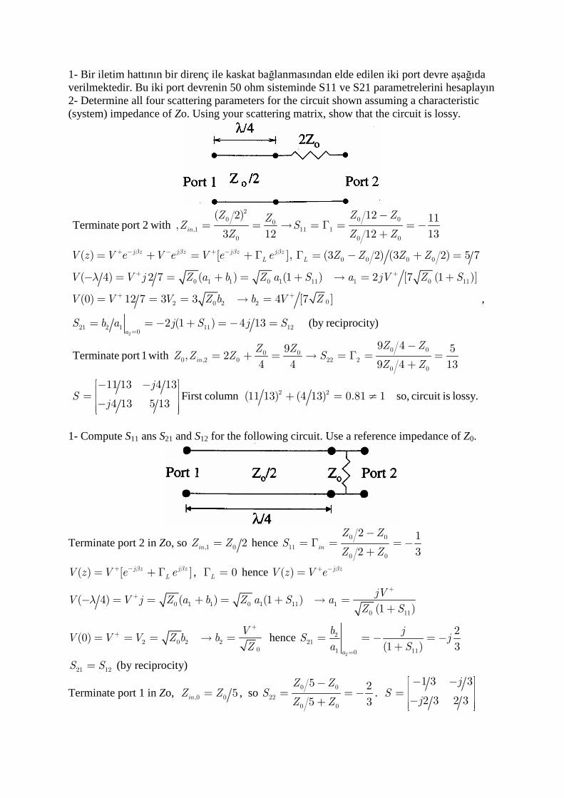
1- Bir iletim hattının bir direnç ile kaskat bağlanmasından elde edilen iki port devre aşağıda verilmektedir. Bu iki port devrenin 50 ohm sisteminde S11 ve S21 parametrelerini hesaplayın 2- Determine all four scattering parameters for the circuit shown assuming a characteristic (system) impedance of Zo. Using your scattering matrix, show that the circuit is lossy.
Terminate port 2 with
+ − − + −
+ +
+
−= = → = Γ = = −
+
= + = + Γ Γ = − + =
− = = + = + → = +
= =
20 0 00
,1 11 1
0 0 0
0 0 0 0
0 1 1 0 1 11 1 0 11
2
( 2) 12 11 ,
3 12 12 13
( ) [ ], (3 2) (3 2) 5 7
( 4) 2 7 ( ) (1 ) 2 [7 (1 )]
(0) 12 7 3
in
j z j z j z j z
L L
Z Z ZZZ S
Z Z Z
V z V e V e V e e Z Z Z Z
V V j Z a b Z a S a jV Z S
V V V
β β β β
λ
(by reciprocity)
Terminate port 1 with
First column
+
=
= → =
= = − + = − =
−= + = → = Γ = =
+
− − = + = −
2
00 2 2
21 2 1 11 120
0 00 00 ,2 0 22 2
0 0
2 2
3 4 [7 ]
2 (1 ) 4 13
9 49 5 , 2
4 4 9 4 13
11 13 4 13 (11 13) (4 13) 0.8
4 13 5 13
a
in
Z b b V Z
S b a j S j S
Z ZZ ZZ Z Z S
Z Z
jS
jso, circuit is lossy.≠1 1
,
1- Compute S11 ans S21 and S12 for the following circuit. Use a reference impedance of Z0.
Terminate port 2 in Zo, so ,1 0 2inZ Z= hence 0 0
11
0 0
2 1
2 3in
Z ZS
Z Z
−= Γ = = −
+
( ) [ ]j z j z
LV z V e eβ β+ −= + Γ , 0LΓ = hence ( ) j zV z V e β+ −=
0 1 1 0 1 11 1
0 11
( 4) ( ) (1 )(1 )
jVV V j Z a b Z a S a
Z Sλ
++− = = + = + → =
+
2 0 2 20
(0)V
V V V Z b bZ
++= = = → = hence
2
221
1 110
2
(1 ) 3a
b jS j
a S=
= = − = −+
21 12S S= (by reciprocity)
Terminate port 1 in Zo, ,0 0 5inZ Z= , so 0 0
22
0 0
5 2
5 3
Z ZS
Z Z
−= = −
+.
1 3 3
2 3 2 3
jS
j
− − = −
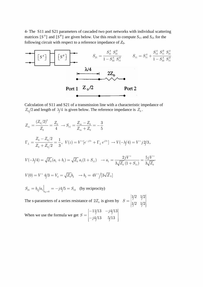
4- The S11 and S21 parameters of cascaded two port networks with individual scattering matrices [ ]AS and [ ]BS are given below. Use this result to compute S11 and S21 for the following circuit with respect to a reference impedance of Z0.
AS BS
Calculation of S11 and S21 of a transmission line with a characteristic impedance of
0 2Z and length of 4λ is given below. The reference impedance is 0Z .
2
0 0 011
0 0
( 2) 3
4 5in
in
in
Z Z Z ZZ S
Z Z Z
−= = → = =−
+
0 0
0 0
2 1
2 3L
Z Z
Z Z
−Γ = =
+, ( ) [ ] ( 4) 2 3j z j z
LV z V e e V V jβ β λ+ − += + Γ → − = ,
0 1 1 0 1 11 1
0 11 0
2 5( 4) ( ) (1 )
3 (1 ) 3
jV jVV Z a b Z a S a
Z S Zλ
+ +
− = + = + → = =+
02 0 2 2(0) 4 3 4 [3 ]V V V Z b b V Z+ += = = → =
2
21 2 1 120
4 5a
S b a j S=
= = − = (by reciprocity)
The s-parameters of a series resistance of 02Z is given by 1 2 1 2
1 2 1 2S
=
When we use the formula we get 11 13 4 13
4 13 5 13
jS
j
− − = −
21 21
21
22 111
A B
A B
S SS
S S=
−
12 11 21
11 11
22 111
A B A
A
A B
S S SS S
S S= +
−
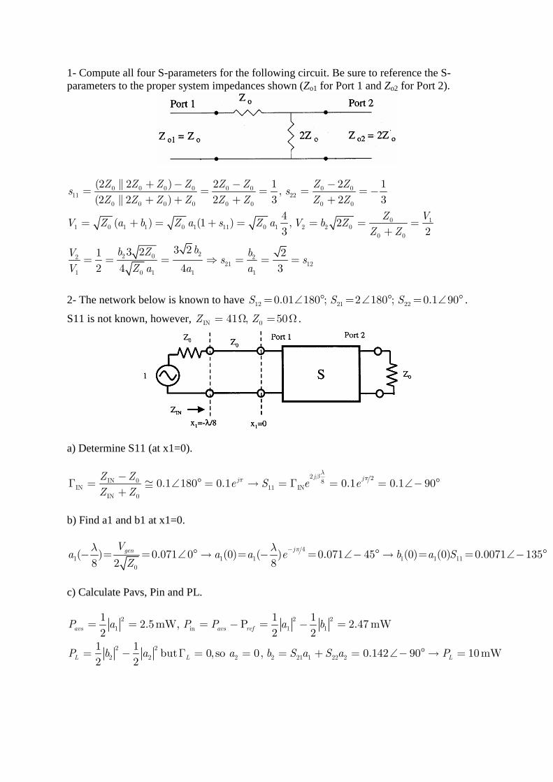
1- Compute all four S-parameters for the following circuit. Be sure to reference the S-parameters to the proper system impedances shown (Zo1 for Port 1 and Zo2 for Port 2).
0 0 0 0 0 0 0 011 22
0 0 0 0 0 0 0 0
0 11 0 1 1 0 1 11 0 1 2 2 0
0 0
22 02 221 12
1 0 1 1 1
(2 2 ) 2 1 2 1,
(2 2 ) 2 3 2 3
4( ) (1 ) , 2
3 2
3 23 21 2
2 4 4 3
Z Z Z Z Z Z Z Zs s
Z Z Z Z Z Z Z Z
Z VV Z a b Z a s Z a V b Z
Z Z
bb ZV bs s
V Z a a a
+ − − −= = = = =−
+ + + +
= + = + = = = =+
= = = ⇒ = = =
2- The network below is known to have 12 21 220.01 180 ; 2 180 ; 0.1 90S S S= ∠ ° = ∠ ° = ∠ ° .
S11 is not known, however, IN 041 , 50Z Z= Ω = Ω .
a) Determine S11 (at x1=0).
2 2IN 0 8IN 11 IN
IN 0
0.1 180 0.1 0.1 0.1 90j jjZ Z
e S e eZ Z
λβ ππ−
Γ = ≅ ∠ ° = → = Γ = = ∠− °+
b) Find a1 and b1 at x1=0.
4
1 1 1 1 1 11
0
( ) 0.071 0 (0) ( ) 0.071 45 (0) (0) 0.0071 1358 2 8
jgenVa a a e b a S
Z
πλ λ −− = = ∠ ° → = − = ∠− ° → = = ∠− °
c) Calculate Pavs, Pin and PL.
2 2 2
1 in 1 1
2 2
2 2 2 2 21 1 22 2
1 1 12.5mW, P 2.47 mW
2 2 21 1
but 0, so 0, 0.142 90 10mW2 2
avs avs ref
L L L
P a P P a b
P b a a b S a S a P
= = = − = − =
= − Γ = = = + = ∠− ° → =
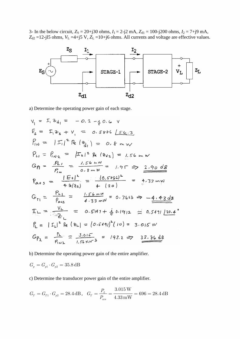
3- In the below circuit, ZS = 20+j30 ohms, I1 = 2-j2 mA, Zd1 = 100-j200 ohms, I2 = 7+j9 mA, Zd2 =12-jl5 ohms, VL =4+j5 V, ZL =10+j6 ohms. All currents and voltage are effective values.
a) Determine the operating power gain of each stage.
b) Determine the operating power gain of the entire amplifier.
1 2 35.8dBp p pG G G= ⋅ =
c) Determine the transducer power gain of the entire amplifier.
1 2 28.4dBT T pG G G= ⋅ = , 3.015W
696 28.4 dB4.33mW
LT
avs
PG
P= = = =
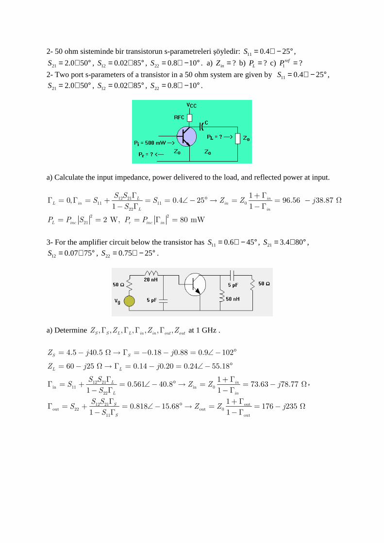
2- 50 ohm sisteminde bir transistorun s-parametreleri şöyledir: 11 0.4 25S = ∠ − ° ,
21 2.0 50S = ∠ ° , 12 0.02 85S = ∠ ° , 22 0.8 10S = ∠ − ° . a) ?inZ = b) ?LP = c) 1 ?refP =
2- Two port s-parameters of a transistor in a 50 ohm system are given by 11 0.4 25S = ∠ − ° ,
21 2.0 50S = ∠ ° , 12 0.02 85S = ∠ ° , 22 0.8 10S = ∠ − ° .
a) Calculate the input impedance, power delivered to the load, and reflected power at input.
Γ + ΓΓ = Γ = + = = ∠− ° → = = − Ω
− Γ −Γ
= = = Γ =
12 2111 11 0
22
2 2
21
10, 0.4 25 96.56 38.87
1 1
2 W, 80 mW
L inL in in
L in
L inc r inc in
S SS S Z Z j
S
P P S P P
3- For the amplifier circuit below the transistor has 11 0.6 45S = ∠ − ° , 21 3.4 80S = ∠ ° ,
12 0.07 75S = ∠ ° , 22 0.75 25S = ∠ − ° .
a) Determine , , , , , , ,S S L L in in out outZ Z Z ZΓ Γ Γ Γ at 1 GHz .
12 21in 11 in 0
22
12 21 outout 22 out 0
11 out
4.5 40.5 0.18 0.88 0.9 102
60 25 0.14 0.20 0.24 55.18
10.561 40.8 73.63 78.77
1 1
10.818 15.68
1 1
S S
L L
L in
L in
S
S
Z j j
Z j j
S SS Z Z j
S
S SS Z Z
S
= − Ω→ Γ = − − = ∠− °
= − Ω→ Γ = − = ∠− °
Γ + ΓΓ = + = ∠− ° → = = − Ω
− Γ −Γ
Γ + ΓΓ = + = ∠− ° → =
− Γ −Γ176 235j= − Ω
,
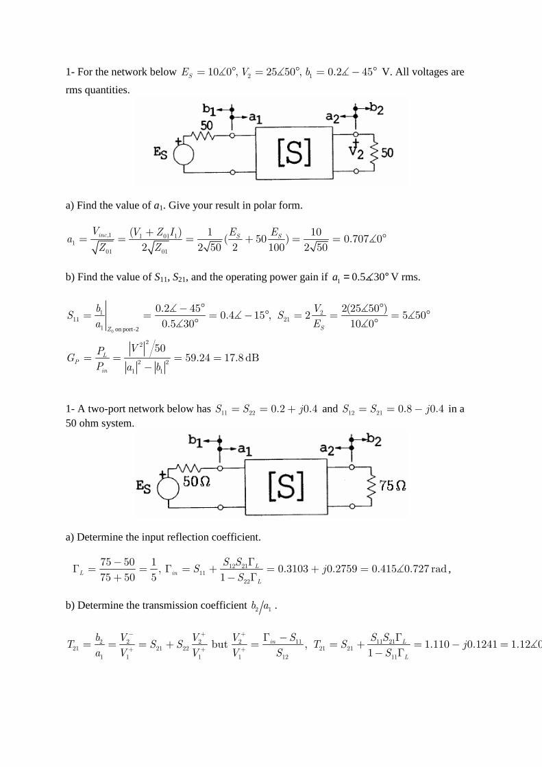
1- For the network below 2 110 0 , 25 50 , 0.2 45SE V b= ° = ° = − °∡ ∡ ∡ V. All voltages are
rms quantities.
a) Find the value of a1. Give your result in polar form.
,1 1 01 11
01 01
( ) 1 10( 50 ) 0.707 0
2 2 50 2 100 2 50
inc S SV V Z I E E
aZ Z
+= = = + = = °∡
b) Find the value of S11, S21, and the operating power gain if 1 0.5 30a = °∡ V rms.
on port-2
− ° °= = = − ° = = = °
° °
= = = =−
∡ ∡∡ ∡
∡ ∡0
1 211 21
1
22
2 2
1 1
0.2 45 2(25 50 )0.4 15 , 2 5 50
0.5 30 10 0
5059.24 17.8 dB
SZ
LP
in
b VS S
a E
VPG
P a b
1- A two-port network below has 11 22 0.2 0.4S S j= = + and 12 21 0.8 0.4S S j= = − in a 50 ohm system.
a) Determine the input reflection coefficient.
12 2111
22
75 50 1, 0.3103 0.2759 0.415 0.727 rad
75 50 5 1L
L in
L
S SS j
S
− ΓΓ = = Γ = + = + =
+ − Γ∡ ,
b) Determine the transmission coefficient 2 1b a .
2 2 2 2 11 11 2121 21 22 21 21
1 1 1 1 12 11
but , 1.110 0.1241 1.12 0.111rad1
in L
L
b V V V S S ST S S T S j
a V V V S S
− + +
+ + +
Γ − Γ= = = + = = + = − =
− Γ∡
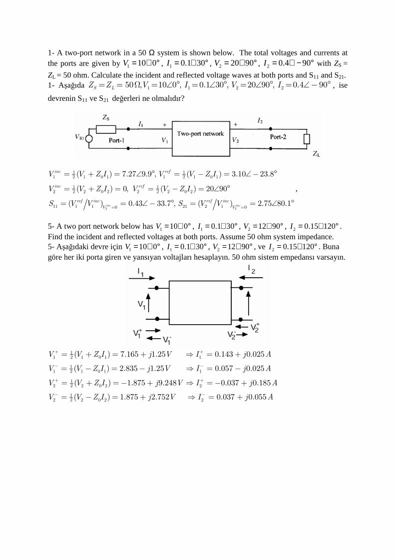
1- A two-port network in a 50 Ω system is shown below. The total voltages and currents at the ports are given by 1 10 0V = ∠ ° , 1 0.1 30I = ∠ ° , 2 20 90V = ∠ ° , 2 0.4 90I = ∠ − ° with ZS =
ZL = 50 ohm. Calculate the incident and reflected voltage waves at both ports and S11 and S21. 1- Aşağıda 1 1 2 250 , 10 0 , 0.1 30 , 20 90 , 0.4 90S LZ Z V I V I= = Ω = ∠ ° = ∠ ° = ∠ ° = ∠− ° , ise
devrenin S11 ve S21 değerleri ne olmalıdır?
2 2
1 12 21 1 0 1 1 1 0 1
1 12 22 2 0 2 2 2 0 2
11 1 1 21 2 10 0
( ) 7.27 9.9 , ( ) 3.10 23.8
( ) 0, ( ) 20 90
( ) 0.43 33.7 , ( ) 2.75 80.1inc inc
inc ref
inc ref
ref inc ref inc
V V
V V Z I V V Z I
V V Z I V V Z I
S V V S V V= =
= + = ∠ ° = − = ∠− °
= + = = − = ∠ °
= = ∠− ° = = ∠ °
,
5- A two port network below has 1 10 0V = ∠ ° , 1 0.1 30I = ∠ ° , 2 12 90V = ∠ ° , 2 0.15 120I = ∠ ° . Find the incident and reflected voltages at both ports. Assume 50 ohm system impedance. 5- Aşağıdaki devre için 1 10 0V = ∠ ° , 1 0.1 30I = ∠ ° , 2 12 90V = ∠ ° , ve 2 0.15 120I = ∠ ° . Buna göre her iki porta giren ve yansıyan voltajları hesaplayın. 50 ohm sistem empedansı varsayın.
121 1 0 1 1
121 1 0 1 1
122 2 0 2 2
122 2 0 2 2
( ) 7.165 1.25 0.143 0.025
( ) 2.835 1.25 0.057 0.025
( ) 1.875 9.248 0.037 0.185
( ) 1.875 2.752 0.037 0.055
V V Z I j V I j A
V V Z I j V I j A
V V Z I j V I j A
V V Z I j V I j A
+ +
− −
+ +
− −
= + = + ⇒ = +
= − = − ⇒ = −
= + =− + ⇒ =− +
= − = + ⇒ = +
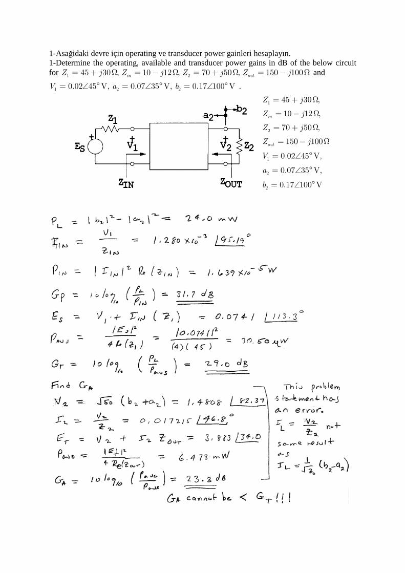
1-Asağidaki devre için operating ve transducer power gainleri hesaplayın. 1-Determine the operating, available and transducer power gains in dB of the below circuit for 1 245 30 , 10 12 , 70 50 , 150 100in outZ j Z j Z j Z j= + Ω = − Ω = + Ω = − Ω and
1 2 20.02 45 V, 0.07 35 V, 0.17 100 VV a b= ∠ ° = ∠ ° = ∠ ° .
1
2
1
2
2
45 30 ,
10 12 ,
70 50 ,
150 100
0.02 45 V,
0.07 35 V,
0.17 100 V
in
out
Z j
Z j
Z j
Z j
V
a
b
= + Ω
= − Ω
= + Ω
= − Ω
= ∠ °
= ∠ °
= ∠ °
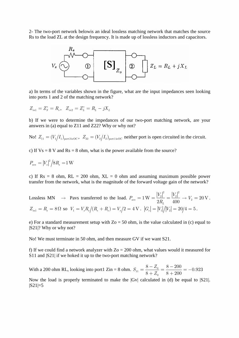
2- The two-port network belowis an ideal lossless matching network that matches the source Rs to the load ZL at the design frequency. It is made up of lossless inductors and capacitors.
a) In terms of the variables shown in the figure, what are the input impedances seen looking into ports 1 and 2 of the matching network?
1in S sZ Z R∗= = , 2in L L LZ Z R jX∗= = − b) If we were to determine the impedances of our two-port matching network, are your answers in (a) equal to Z11 and Z22? Why or why not? No! 11 1 1 port2 isOC( )Z V I= , 22 2 2 port1isOC( )Z V I= neither port is open circuited in the circuit.
c) If Vs = 8 V and Rs = 8 ohm, what is the power available from the source?
28 1Wavs s sP V R= =
c) If Rs = 8 ohm, RL = 200 ohm, XL = 0 ohm and assuming maximum possible power transfer from the network, what is the magnitude of the forward voltage gain of the network?
Lossless MN → Pavs transferred to the load. 2 2
2 221W 20V
2 400avs
L
V VP V
R= = = → = .
1 8in sZ R= = Ω so 1 ( ) 2 4 Vs s s s sV V R R R V= + = = . 1 2 20 4 5vG V V= = = .
e) For a standard measurement setup with Zo = 50 ohm, is the value calculated in (c) equal to |S21|? Why or why not? No! We must terminate in 50 ohm, and then measure GV if we want S21. f) If we could find a network analyzer with Zo = 200 ohm, what values would it measured for S11 and |S21| if we hoked it up to the two-port matching network?
With a 200 ohm RL, looking into port1 Zin = 8 ohm. 011
0
8 8 2000.923
8 8 200
ZS
Z
− −= = =−
+ +
Now the load is properly terminated to make the |Gv| calculated in (d) be equal to |S21|. |S21|=5
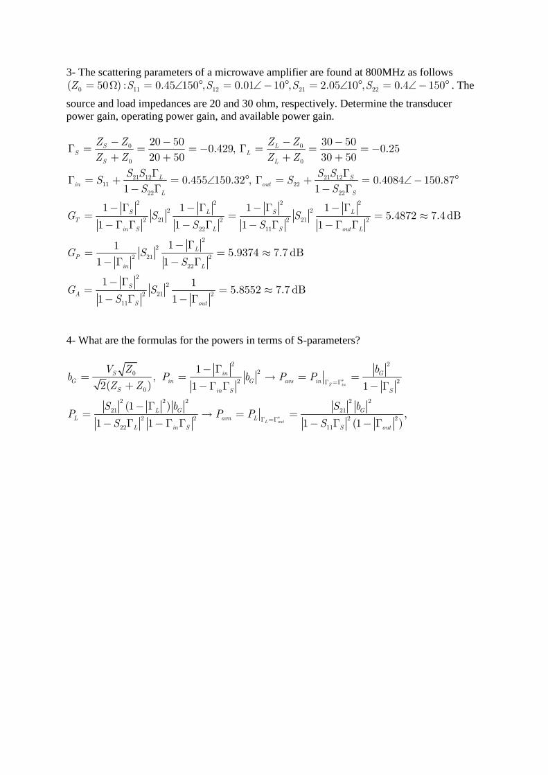
3- The scattering parameters of a microwave amplifier are found at 800MHz as follows
0 11 12 21 22( 50 ) : 0.45 150 , 0.01 10 , 2.05 10 , 0.4 150Z S S S S= Ω = ∠ ° = ∠− ° = ∠ ° = ∠− ° . The
source and load impedances are 20 and 30 ohm, respectively. Determine the transducer power gain, operating power gain, and available power gain.
0 0
0 0
21 12 21 1211 22
22 22
2 2 2 22 2
21 212 2 2
22 11
20 50 30 500.429, 0.25
20 50 30 50
0.455 150.32 , 0.4084 150.871 1
1 1 1 1
1 1 1 1
S LS L
S L
L Sin out
L S
S L S L
T
in S L S o
Z Z Z Z
Z Z Z Z
S S S SS S
S S
G S SS S
− − − −Γ = = = − Γ = = = −
+ + + +
Γ ΓΓ = + = ∠ ° Γ = + = ∠− °
− Γ − Γ
− Γ − Γ − Γ − Γ= =
−Γ Γ − Γ − Γ −Γ2
22
212 2
22
22
212 2
11
5.4872 7.4 dB
115.9374 7.7 dB
1 1
1 15.8552 7.7 dB
1 1
ut L
L
P
in L
S
A
S out
G SS
G SS
= ≈Γ
− Γ= = ≈
− Γ − Γ
− Γ= = ≈
− Γ − Γ
4- What are the formulas for the powers in terms of S-parameters?
2 220
2 2
0
2 2 2 2 2
21 212 2 2 2
22 11
1,
2( ) 1 1
(1 ),
1 1 1 (1 )
S in
L out
S in G
G in G avs in
S in S S
L G G
L avn L
L in S S out
V Z bb P b P P
Z Z
S b S bP P P
S S
∗
∗
Γ =Γ
Γ =Γ
− Γ= = → = =
+ −Γ Γ − Γ
− Γ= → = =
− Γ −Γ Γ − Γ − Γ
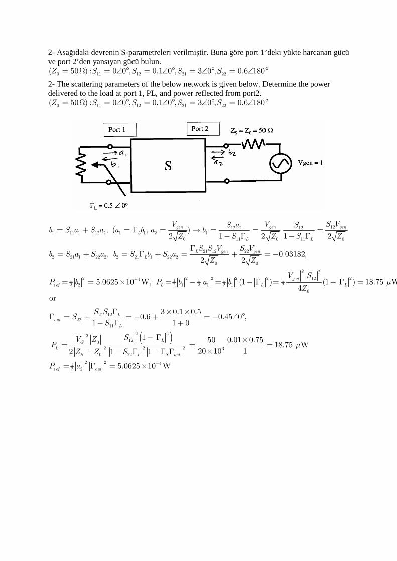
2- Asağıdaki devrenin S-parametreleri verilmiştir. Buna göre port 1’deki yükte harcanan gücü ve port 2’den yansıyan gücü bulun.
0 11 12 21 22( 50 ) : 0 0 , 0.1 0 , 3 0 , 0.6 180Z S S S S= Ω = ∠ ° = ∠ ° = ∠ ° = ∠ °
2- The scattering parameters of the below network is given below. Determine the power delivered to the load at port 1, PL, and power reflected from port2.
0 11 12 21 22( 50 ) : 0 0 , 0.1 0 , 3 0 , 0.6 180Z S S S S= Ω = ∠ ° = ∠ ° = ∠ ° = ∠ °
1212 2 121 11 1 12 2 1 1 2 1
0 11 0 11 0
21 12 22
2 21 1 22 2 2 21 1 22 2
0 0
2 2 2 2 241 1 1 12 2 2 2r 2 1 1 1
, ( , )2 1 2 1 2
, 0.03182,2 2
5.0625 10 W, (1 )
gen gen gen
L
L L
L gen gen
L
ef L L
V V S VS a Sb S a S a a b a b
Z S Z S Z
S S V S Vb S a S a b S b S a
Z Z
P b P b a b−
= + = Γ = → = = =− Γ − Γ
Γ= + = Γ + = + =−
= = × = − = − Γ =
( )
2 2
21212
0
21 1222
11
2 22120
2 2 2 3
0 22
2 2 412r 2
(1 ) 18.75 W4
or
3 0.1 0.50.6 0.45 0 ,
1 1 0
1 50 0.01 0.7518.75 W
20 10 12 1 1
5.0625 10 W
gen
L
Lout
L
LG
L
S L S out
ef out
V S
Z
S SS
S
SV ZP
Z Z S
P a
µ
µ
−
− Γ =
Γ × ×Γ = + = − + = − ∠ °
− Γ +
− Γ ×= = =
×+ − Γ −Γ Γ
= Γ = ×
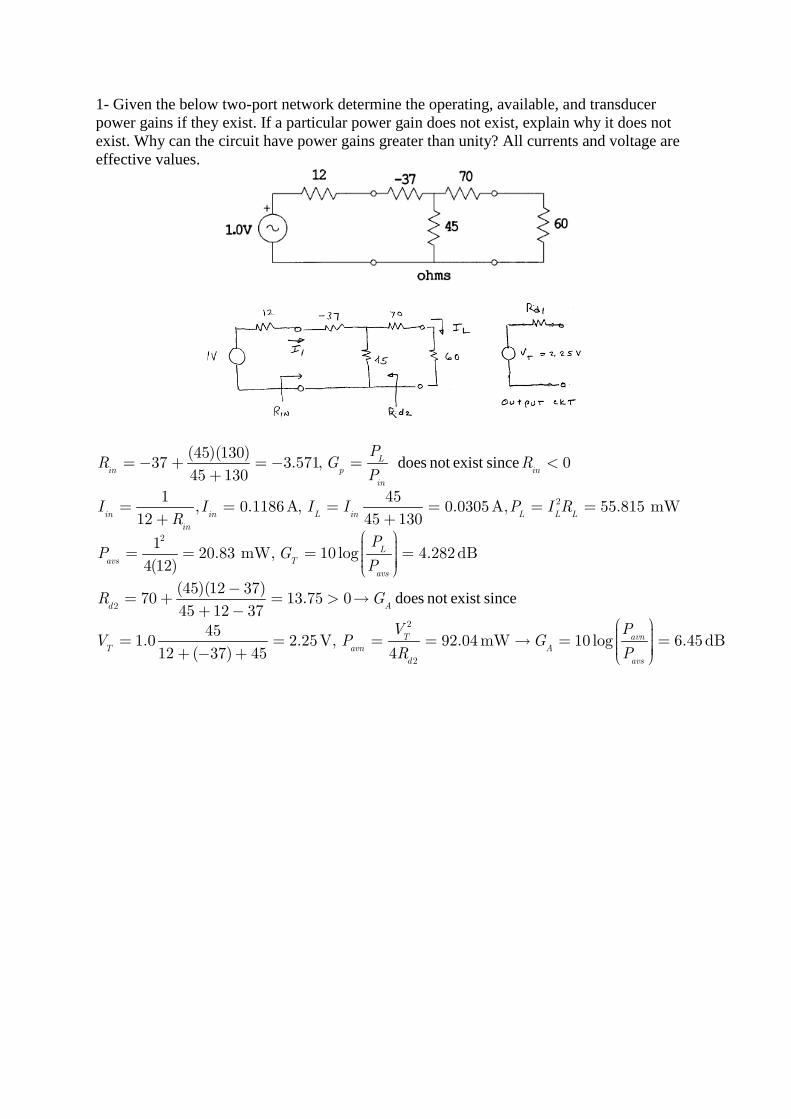
1- Given the below two-port network determine the operating, available, and transducer power gains if they exist. If a particular power gain does not exist, explain why it does not exist. Why can the circuit have power gains greater than unity? All currents and voltage are effective values.
does not exist since
2
2
2
(45)(130)37 3.571, 0
45 130
1 45, 0.1186A, 0.0305A, 55.815 mW
12 45 130
120.83 mW, 10 log 4.282dB
4(12)
(45)(12 37)70
L
in p in
in
in in L in L L L
in
L
avs T
avs
d
PR G R
P
I I I I P I RR
PP G
P
R
=− + = − = <+
= = = = = =+ +
= = = = −
= + does not exist since
2
2
13.75 045 12 37
451.0 2.25V, 92.04mW 10 log 6.45dB
12 ( 37) 45 4
A
T avn
T avn A
d avs
G
V PV P G
R P
= > →+ −
= = = = → = = + − +
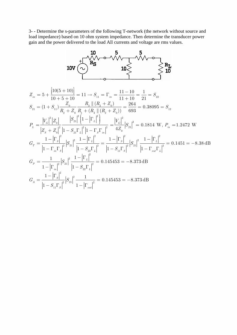
3- - Determine the s-parameters of the following T-network (the network without source and load impedance) based on 10 ohm system impedance. Then determine the transducer power gain and the power delivered to the load All currents and voltage are rms values.
11 22
0 3 2 0
21 11 12
2 0 1 3 2 02 2
2 2
21 20
212 2 2
00 21
10(5 10) 11 10 15 11
10 5 10 11 10 21( ) 264
(1 ) 0.38095( ( )) 693
10.1814 W, 1.2472 W
41 1
in in
LG G
L in
S L S in
T
Z S S
Z R R ZS S S
R Z R R R Z
SV Z VP S P
ZZ Z S
G
+ − = + = → = Γ = = =+ + +
+= + = = =
+ + + − Γ
= = = =+ − Γ − Γ Γ
2 2 2 2
2 2
21 212 2 2 2
22 11
2
2
212 2
22
2
2
212 2
11
1 1 1 10.1451 8.38 dB
1 1 1 1
110.145453 8.373 dB
1 1
1 10.145453 8.373 dB
1 1
S L S L
in S L S out L
L
P
in L
S
A
S out
S S
S S
G SS
G S
S
− Γ − Γ − Γ − Γ= = = = −
− Γ Γ − Γ − Γ − Γ Γ
− Γ= = = −
− Γ − Γ
− Γ= = = −
− Γ − Γ
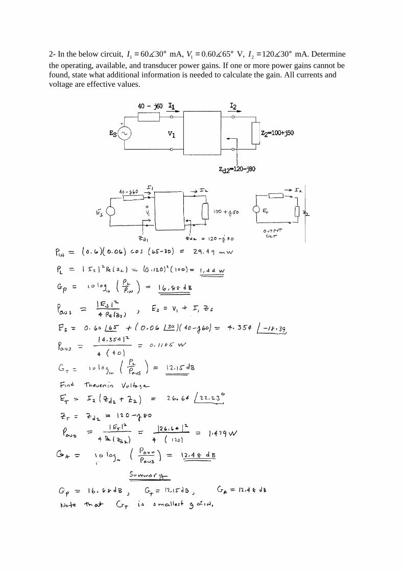
2- In the below circuit, 1 60 30I = °∡ mA, 1 0.60 65V = °∡ V, 2 120 30I = °∡ mA. Determine
the operating, available, and transducer power gains. If one or more power gains cannot be found, state what additional information is needed to calculate the gain. All currents and voltage are effective values.
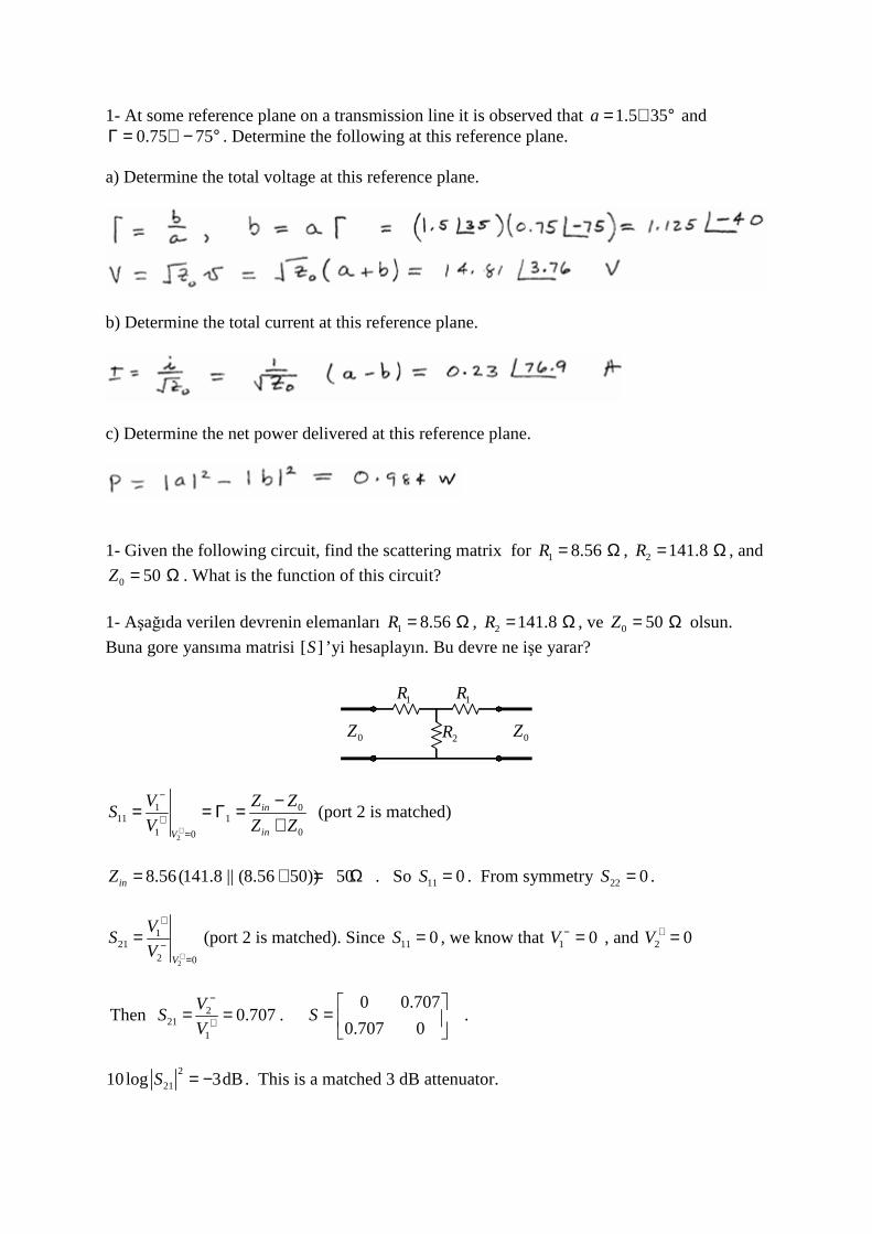
1- At some reference plane on a transmission line it is observed that 1.5 35a = ∠ ° and 0.75 75Γ = ∠ − ° . Determine the following at this reference plane.
a) Determine the total voltage at this reference plane.
b) Determine the total current at this reference plane.
c) Determine the net power delivered at this reference plane.
1- Given the following circuit, find the scattering matrix for 1 8.56R = Ω , 2 141.8R = Ω , and
0 50Z = Ω . What is the function of this circuit?
1- Aşağıda verilen devrenin elemanları 1 8.56R = Ω , 2 141.8R = Ω , ve 0 50Z = Ω olsun.
Buna gore yansıma matrisi [ ]S ’yi hesaplayın. Bu devre ne işe yarar?
1R 1R
0Z 0Z2R
2
0111 1
1 00
in
inV
Z ZVS
V Z Z+
−
+=
−= = Γ =+
(port 2 is matched)
8.56(141.8 || (8.56 50)) 50inZ = + = Ω . So 11 0S = . From symmetry 22 0S = .
2
121
2 0V
VS
V +
+
−=
= (port 2 is matched). Since 11 0S = , we know that 1 0V − = , and 2 0V + =
Then 221
1
0.707V
SV
−
+= = . 0 0.707
0.707 0S
=
.
2
2110log 3dBS = − . This is a matched 3 dB attenuator.
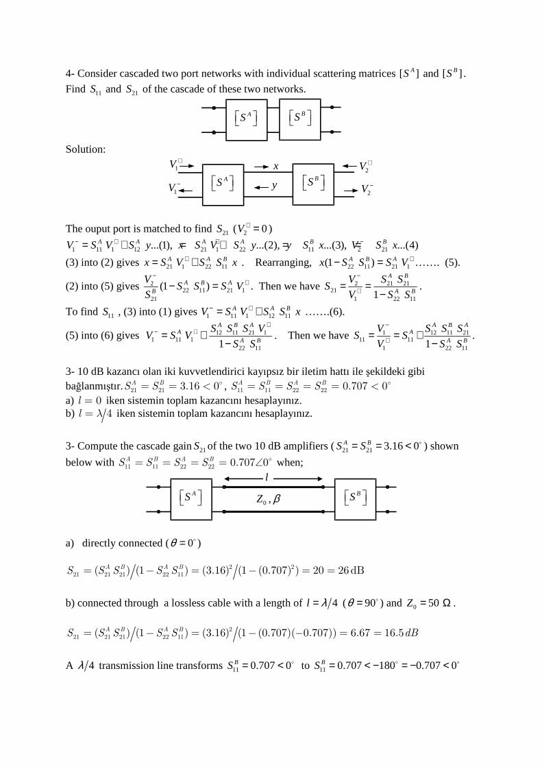
4- Consider cascaded two port networks with individual scattering matrices [ ]AS and [ ]BS .
Find 11S and 21S of the cascade of these two networks.
AS BS
Solution:
AS BS
1V +x
y1V −
2V +
2V −
The ouput port is matched to find 21S ( 2 0V + = )
1 11 1 12 21 1 22 11 2 21...(1), ...(2), ...(3), ...(4)A A A A B BV S V S y x S V S y y S x V S x− + + −= + = + = =
(3) into (2) gives 21 1 22 11A A Bx S V S S x+= + . Rearranging, 22 11 21 1(1 )A B Ax S S S V +− = ……. (5).
(2) into (5) gives 222 11 21 1
21
(1 )A B AB
VS S S V
S
−+− = . Then we have 2 21 21
211 22 111
A B
A B
V S SS
V S S
−
+= =−
.
To find 11S , (3) into (1) gives 1 11 1 12 11A A BV S V S S x− += + …….(6).
(5) into (6) gives 12 11 21 11 11 1
22 111
A B AA
A B
S S S VV S V
S S
+− += +
−. Then we have 1 12 11 21
11 111 22 111
A B AA
A B
V S S SS S
V S S
−
+= = +−
.
3- 10 dB kazancı olan iki kuvvetlendirici kayıpsız bir iletim hattı ile şekildeki gibi bağlanmıştır. 21 21 3.16 0A BS S= = < , 11 11 22 22 0.707 0A B A BS S S S= = = = < a) 0l = iken sistemin toplam kazancını hesaplayınız. b) 4l λ= iken sistemin toplam kazancını hesaplayınız.
3- Compute the cascade gain21S of the two 10 dB amplifiers (21 21 3.16 0A BS S= = < ) shown
below with 11 11 22 22 0.707 0A B A BS S S S= = = = ∠ when;
AS BS 0 ,Z β
l
a) directly connected ( 0θ = )
2 221 21 21 22 11( ) (1 ) (3.16) (1 (0.707) ) 20 26dBA B A BS S S S S= − = − = =
b) connected through a lossless cable with a length of 4l λ= ( 90θ = ) and 0 50Z = Ω .
2
21 21 21 22 11( ) (1 ) (3.16) (1 (0.707)( 0.707)) 6.67 16.5A B A BS S S S S dB= − = − − = =
A 4λ transmission line transforms 11 0.707 0BS = < to 11 0.707 180 0.707 0BS = < − = − <
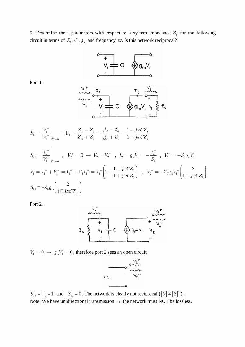
5- Determine the s-parameters with respect to a system impedance 0Z for the following
circuit in terms of 0Z ,C , mg and frequency ω . Is this network reciprocal?
Port 1.
2
101 0 0
11 1 11 0 0 00
1
1
j Cin
j CinV
ZV Z Z j CZS
V Z Z Z j CZ
ω
ω
ω
ω+
−
+
=
−− −= = Γ = = =
+ + +
2
221
1 0V
VS
V +
−
+
=
= , 2 2 20V V V+ −= → = , 22 1
0
m
VI g V
Z
−
= = − , 2 0 1mV Z g V− = −
01 1 1 1 1 1 1
0
11
1
j CZV V V V V V
j CZ
ω
ω
+ − + + + − = + = + Γ = + +
, 2 0 1
0
2
1mV Z g V
j CZω
− + = − +
21 00
2
1mS Z gj CZω
= − +
Port 2.
1 10 0mV g V= → = , therefore port 2 sees an open circuit
22 2 1S = Γ = and 12 0S = . The network is clearly not reciprocal ([ ] [ ]tS S≠ ) .
Note: We have unidirectional transmission → the network must NOT be lossless.
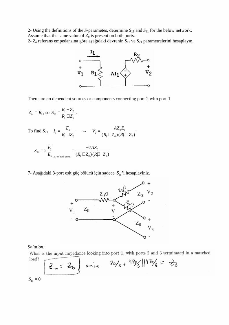
2- Using the definitions of the S-parametes, determine S11 and S21 for the below network. Assume that the same value of Zo is present on both ports. 2- Zo referans empedansına göre aşağıdaki devrenin S11 ve S21 parametrelerini hesaplayın.
There are no dependent sources or components connecting port-2 with port-1
1inZ R= , so 1 011
1 0
R ZS
R Z
−=+
.
To find S21 11 0
sEI
R Z=
+ → 0
21 0 2 0( ) ( )
sAZ EV
R Z R Z
−=+ +
0
0221
1 0 2 0on both ports
22
( ) ( )s Z
AZVS
E R Z R Z
−= =+ +
7- Aşağıdaki 3-port eşit güç bölücü için sadece 11S ’i hesaplayiniz.
Solution:
11 0S =
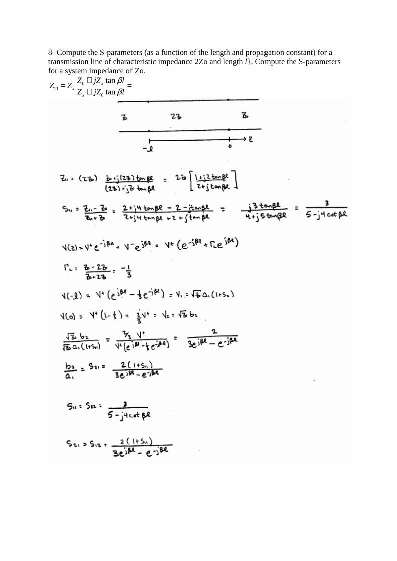
8- Compute the S-parameters (as a function of the length and propagation constant) for a transmission line of characteristic impedance 2Zo and length l. Compute the S-parameters for a system impedance of Zo.
011
0
tan
tanx
xx
Z jZ lZ Z
Z jZ l
ββ
+= =+
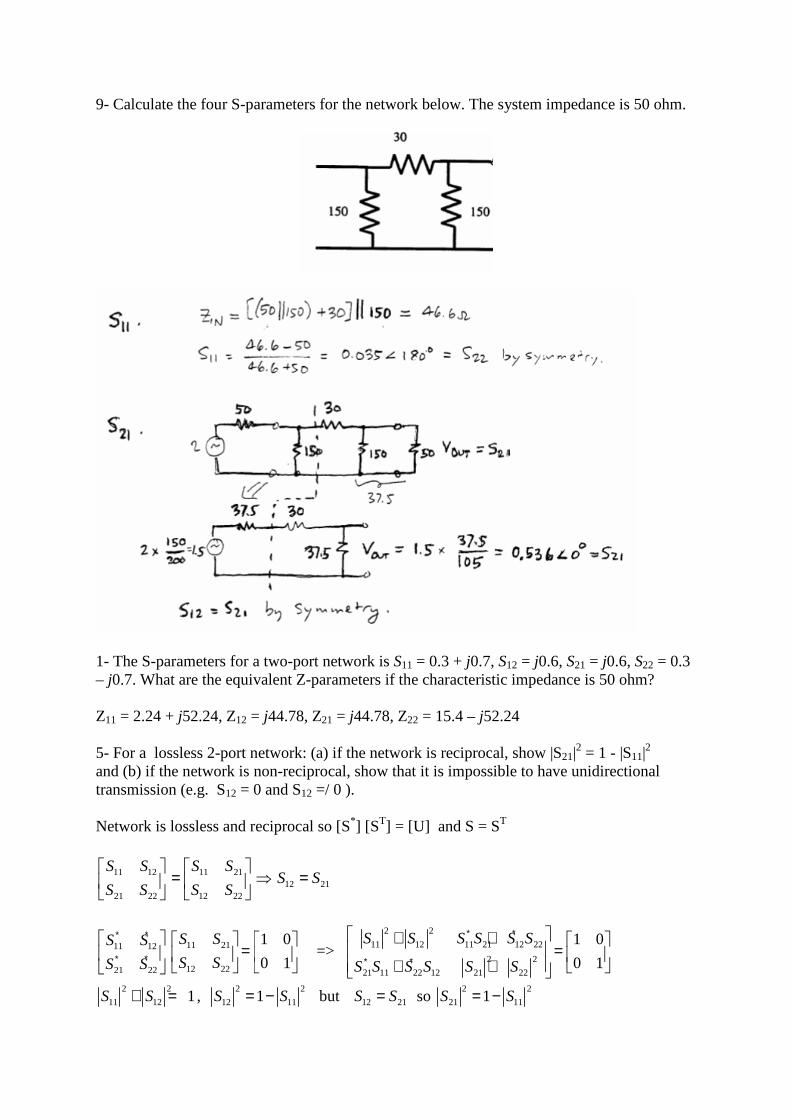
9- Calculate the four S-parameters for the network below. The system impedance is 50 ohm.
1- The S-parameters for a two-port network is S11 = 0.3 + j0.7, S12 = j0.6, S21 = j0.6, S22 = 0.3 – j0.7. What are the equivalent Z-parameters if the characteristic impedance is 50 ohm? Z11 = 2.24 + j52.24, Z12 = j44.78, Z21 = j44.78, Z22 = 15.4 – j52.24 5- For a lossless 2-port network: (a) if the network is reciprocal, show |S21|
2 = 1 - |S11|2
and (b) if the network is non-reciprocal, show that it is impossible to have unidirectional transmission (e.g. S12 = 0 and S12 =/ 0 ). Network is lossless and reciprocal so [S*] [ST] = [U] and S = ST
11 12 11 2112 21
21 22 12 22
S S S SS S
S S S S
= ⇒ =
11 2111 12
12 2221 22
1 0
0 1
S SS S
S SS S
∗ ∗
∗ ∗
=
=>
2 2
11 12 11 21 12 22
2 2
21 11 22 12 21 22
1 0
0 1
S S S S S S
S S S S S S
∗ ∗
∗ ∗
+ + = + +
2 2
11 12 1S S+ = , 2 2
12 111S S= − but 12 21S S= so 2 2
21 111S S= −
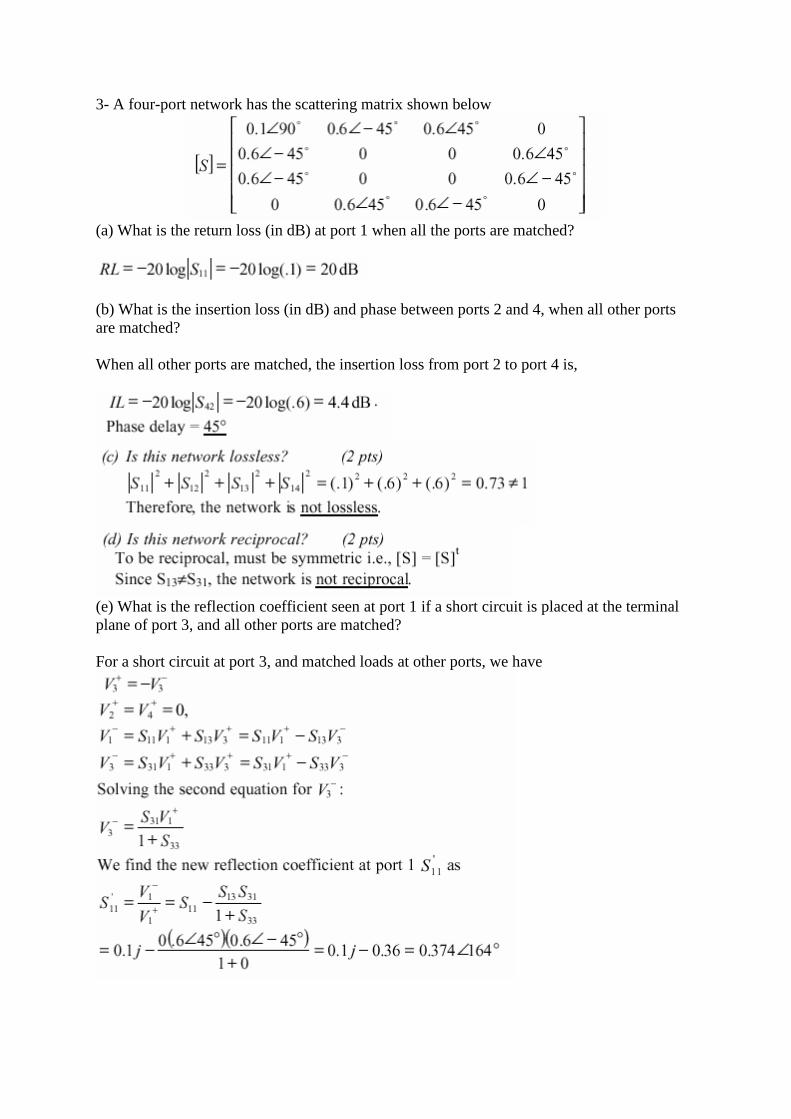
3- A four-port network has the scattering matrix shown below
(a) What is the return loss (in dB) at port 1 when all the ports are matched?
(b) What is the insertion loss (in dB) and phase between ports 2 and 4, when all other ports are matched? When all other ports are matched, the insertion loss from port 2 to port 4 is,
(e) What is the reflection coefficient seen at port 1 if a short circuit is placed at the terminal plane of port 3, and all other ports are matched? For a short circuit at port 3, and matched loads at other ports, we have
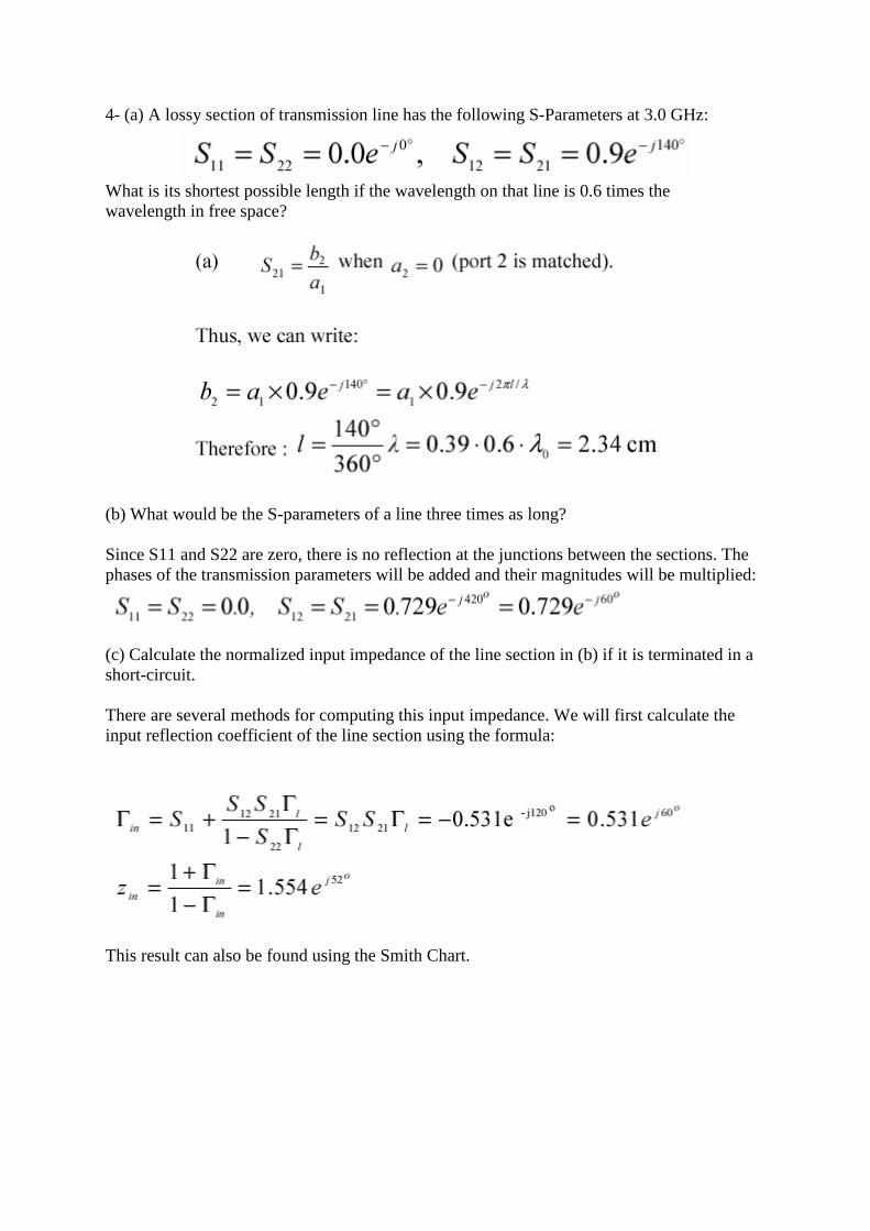
4- (a) A lossy section of transmission line has the following S-Parameters at 3.0 GHz:
What is its shortest possible length if the wavelength on that line is 0.6 times the wavelength in free space?
(b) What would be the S-parameters of a line three times as long? Since S11 and S22 are zero, there is no reflection at the junctions between the sections. The phases of the transmission parameters will be added and their magnitudes will be multiplied:
(c) Calculate the normalized input impedance of the line section in (b) if it is terminated in a short-circuit. There are several methods for computing this input impedance. We will first calculate the input reflection coefficient of the line section using the formula:
This result can also be found using the Smith Chart.
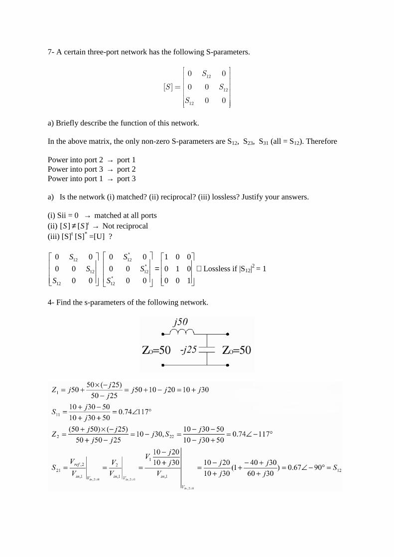
7- A certain three-port network has the following S-parameters.
12
12
12
0 0
[ ] 0 0
0 0
S
S S
S
=
a) Briefly describe the function of this network. In the above matrix, the only non-zero S-parameters are S12, S23, S31 (all = S12). Therefore Power into port 2 → port 1 Power into port 3 → port 2 Power into port 1 → port 3 a) Is the network (i) matched? (ii) reciprocal? (iii) lossless? Justify your answers. (i) Sii = 0 → matched at all ports (ii) [ ] [ ] tS S≠ → Not reciprocal (iii) [S] t [S]* =[U] ?
12 12
12 12
12 12
0 0 0 0 1 0 0
0 0 0 0 0 1 0
0 0 0 0 0 0 1
S S
S S
S S
∗
∗
∗
=
∴Lossless if |S12|2 = 1
4- Find the s-parameters of the following network.
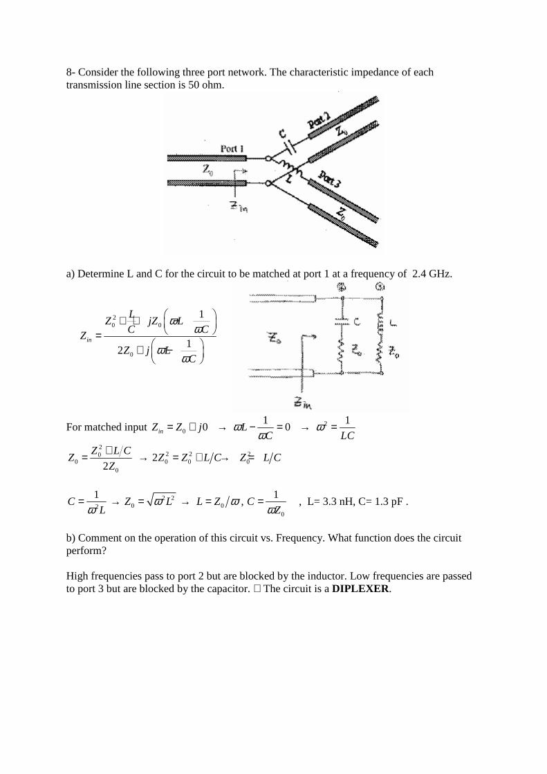
8- Consider the following three port network. The characteristic impedance of each transmission line section is 50 ohm.
a) Determine L and C for the circuit to be matched at port 1 at a frequency of 2.4 GHz.
For matched input 0 0inZ Z j= + → 1
0LC
ωω
− = → 2 1
LCω =
22 2 20
0 0 0 00
22
Z L CZ Z Z L C Z L C
Z
+= → = + → =
2 2
0 020
1 1,C Z L L Z C
L Zω ω
ω ω= → = → = = , L= 3.3 nH, C= 1.3 pF .
b) Comment on the operation of this circuit vs. Frequency. What function does the circuit perform? High frequencies pass to port 2 but are blocked by the inductor. Low frequencies are passed to port 3 but are blocked by the capacitor. ∴The circuit is a DIPLEXER.
20 0
0
1
12
in
LZ jZ L
C CZ
Z j LC
ωω
ωω
+ + − =
+ −
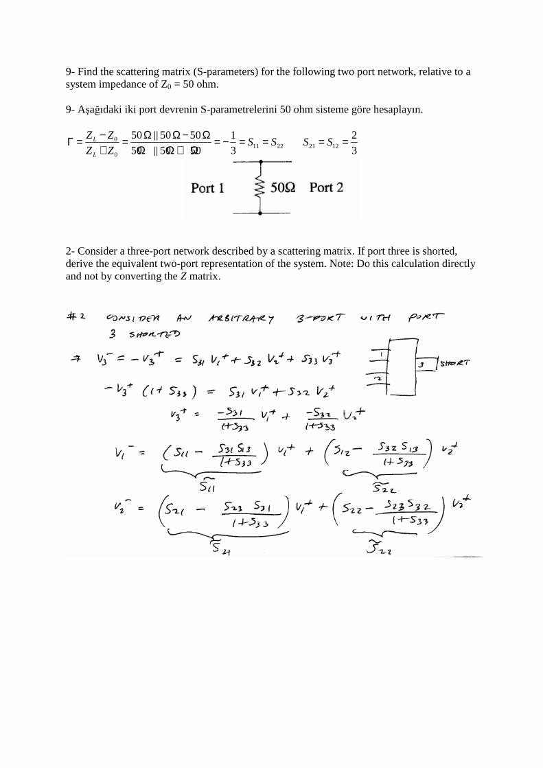
9- Find the scattering matrix (S-parameters) for the following two port network, relative to a system impedance of Z0 = 50 ohm. 9- Aşağıdaki iki port devrenin S-parametrelerini 50 ohm sisteme göre hesaplayın.
011 22
0
50 50 50 1
50 50 50 3L
L
Z ZS S
Z Z
− Ω Ω − ΩΓ = = = − = =+ Ω Ω + Ω
21 12
2
3S S= =
2- Consider a three-port network described by a scattering matrix. If port three is shorted, derive the equivalent two-port representation of the system. Note: Do this calculation directly and not by converting the Z matrix.
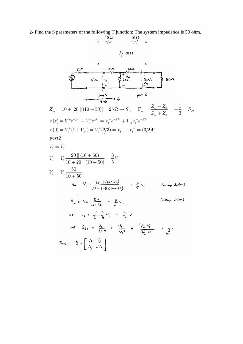
2- Find the S parameters of the following T junction: The system impedance is 50 ohm.
[ ] 011 22
0
1 1 1 1
1 1 1 1 1
2 2
1 1
2
110 20 (10 50) 25
3
( )
(0) (1 ) (2 3) (3 2)
2
20 (10 50) 3
10 20 (10 50) 5
50
10 50
Lin in
L
j z j z j z j z
in
in
a
a
Z ZZ S S
Z Z
V z V e V e V e V e
V V V V V V
port
V V
V V V
V V
β β β β+ − − + − + −
+ + +
−
−= + + = Ω→ = Γ = = − =
+
= + = + Γ
= + Γ = = → =
=
+= =
+ +
=+
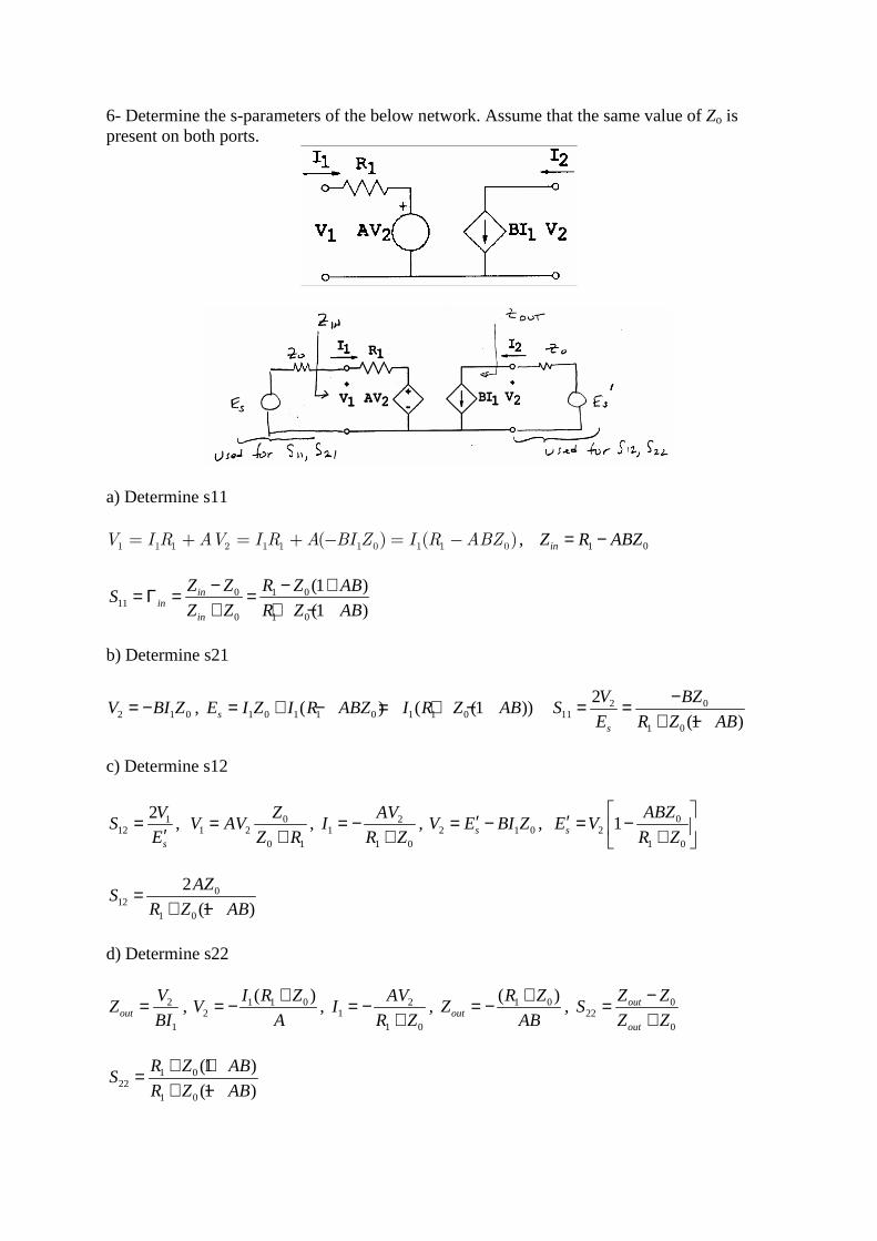
6- Determine the s-parameters of the below network. Assume that the same value of Zo is present on both ports.
a) Determine s11
1 1 1 2 1 1 1 0 1 1 0( ) ( )V I R AV I R A BI Z I R ABZ= + = + − = − , 1 0inZ R ABZ= −
0 1 011
0 1 0
(1 )
(1 )in
inin
Z Z R Z ABS
Z Z R Z AB
− − += Γ = =+ + −
b) Determine s21
2 1 0V BI Z= − , 1 0 1 1 0 1 1 0( ) ( (1 ))sE I Z I R ABZ I R Z AB= + − = + − 0211
1 0
2
(1 )s
BZVS
E R Z AB
−= =+ −
c) Determine s12
112
2
s
VS
E=
′, 0
1 20 1
ZV AV
Z R=
+, 2
11 0
AVI
R Z= −
+, 2 1 0sV E BI Z′= − , 0
21 0
1s
ABZE V
R Z
′ = − +
012
1 0
2
(1 )
AZS
R Z AB=
+ −
d) Determine s22
2
1out
VZ
BI= , 1 1 0
2
( )I R ZV
A
+= − , 21
1 0
AVI
R Z= −
+, 1 0( )
out
R ZZ
AB
+= − , 022
0
out
out
Z ZS
Z Z
−=+
1 022
1 0
(1 )
(1 )
R Z ABS
R Z AB
+ +=+ −
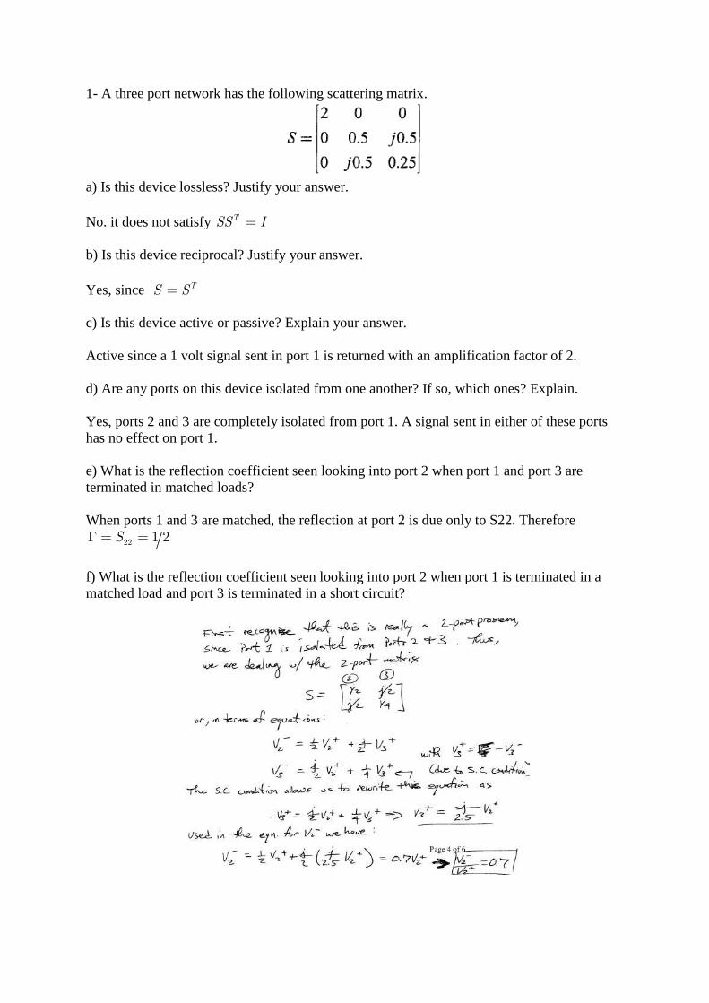
1- A three port network has the following scattering matrix.
a) Is this device lossless? Justify your answer. No. it does not satisfy TSS I= b) Is this device reciprocal? Justify your answer. Yes, since TS S= c) Is this device active or passive? Explain your answer. Active since a 1 volt signal sent in port 1 is returned with an amplification factor of 2. d) Are any ports on this device isolated from one another? If so, which ones? Explain. Yes, ports 2 and 3 are completely isolated from port 1. A signal sent in either of these ports has no effect on port 1. e) What is the reflection coefficient seen looking into port 2 when port 1 and port 3 are terminated in matched loads? When ports 1 and 3 are matched, the reflection at port 2 is due only to S22. Therefore
22 1 2SΓ = =
f) What is the reflection coefficient seen looking into port 2 when port 1 is terminated in a matched load and port 3 is terminated in a short circuit?
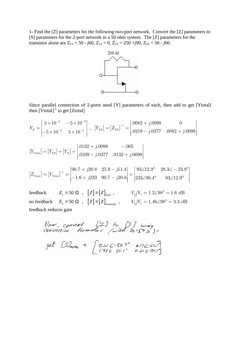
1- Find the [Z] parameters for the following two-port network. Convert the [Z] parameters to [S] parameters for the 2-port network in a 50 ohm system. The [Z] parameters for the transistor alone are Z11 = 50 - j60, Z12 = 0, Z21 = 250 +j90, Z22 = 50 - j60.
Since parallel connection of 2-ports need [Y] parameters of each, then add to get [Ytotal] then [Ytotal]-1 to get [Ztotal]
3 3
3 3
5 10 5 10
5 10 5 10RY
− −
− −
× − × = − × ×
, [ ] [ ]1
.0082 .0098 0
.0219 .0377 .0082 .0098TR TR
jY Z
j j
− + = = − +
[ ] [ ] [ ].0132 .0098 .005
.0169 .0377 .0132 .0098Total TR R
jY Y Y
j j
+ − = + = − +
[ ] [ ]1
90.7 20.8 25.9 11.4 93 12.9 28.3 23.8
1.6 233 90.7 20.8 233 90.4 93 12.9Total Total
j jZ Y
j j
− + − ∠ ° ∠− ° = = = − + − ∠ ° ∠ °
feedback 50LZ = Ω , [ ] [ ]TOT
Z Z= , 2 1 1.2 98 1.6 dBV V = ∠ ° =
no feedback 50LZ = Ω , [ ] [ ]transistorZ Z= , 2 1 1.46 98 3.3 dBV V = ∠ ° =
feedback reduces gain
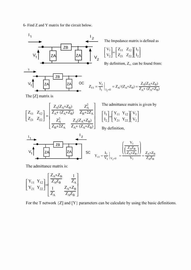
6- Find Z and Y matrix for the circuit below.
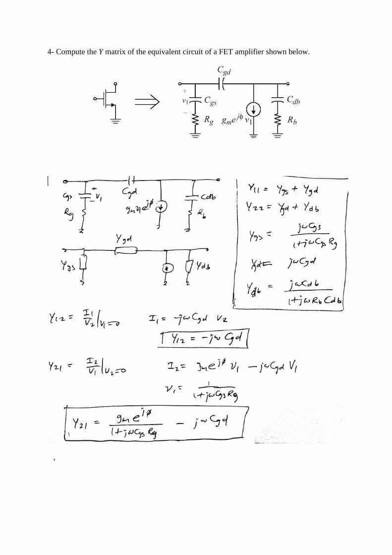
4- Compute the Y matrix of the equivalent circuit of a FET amplifier shown below.
,


![Challenger – Serie IP - sinwire.com · Dos tramos de cable coaxial [FI, 50 Ω conectorizado] para interconectar IDUs y ODUs. Figura 1.4 Modo con Diversidad de Frecuencia [una antena](https://static.fdocument.org/doc/165x107/5be7465c09d3f26f698c54d5/challenger-serie-ip-dos-tramos-de-cable-coaxial-fi-50-conectorizado.jpg)