01 EN 3P188821-1C...• Electrical work should be carried out in accordance with the installation...
13
INSTALLATION MANUAL R410A Split Series Models RXS50F2V1B RKS50F2V1B RXS60F2V1B RKS60F2V1B RXS50E3V1B RKS50E3V1B RXS60E3V1B RKS60E3V1B RXS71E3V1B RKS71E3V1B RYN50E3V1B RYN60E3V1B RN50E3V1B RN60E3V1B ARXS50E3V1B Deutsch Français Nederlands Español Italiano ΕλληνικÜ Portugues Рóссêий Türkçe English Montaj kýlavuzlarý R410A Split serisi Installation manual R410A Split series Installationsanleitung Split-Baureihe R410A Manuel d’installation Série split R410A Montagehandleiding R410A Split-systeem Manual de instalación Serie Split R410A Manuale d’installazione Serie Multiambienti R410A Εγχειρßδιο εγκατÜστασηò διαιροýìενηò σειρÜò R410A Manual de Instalação Série split R410A Рóêоводство по монтажó Серия R410A с раздельной óстановêой
Transcript of 01 EN 3P188821-1C...• Electrical work should be carried out in accordance with the installation...
INSTALLATION MANUALR410A Split Series
Models RXS50F2V1B RKS50F2V1BRXS60F2V1B RKS60F2V1BRXS50E3V1B RKS50E3V1BRXS60E3V1B RKS60E3V1BRXS71E3V1B RKS71E3V1BRYN50E3V1B RYN60E3V1BRN50E3V1B RN60E3V1BARXS50E3V1B
Deutsch
Français
Nederlands
Español
Italiano
ΕλληνικÜ
Portugues
Рóссêий
Türkçe
English
Montaj kýlavuzlarý R410A Split serisi
Installation manualR410A Split series
InstallationsanleitungSplit-Baureihe R410A
Manuel d’installationSérie split R410A
MontagehandleidingR410A Split-systeem
Manual de instalaciónSerie Split R410A
Manuale d’installazioneSerie Multiambienti R410A
Εγχειρßδιο εγκατÜστασηòδιαιροýìενηò σειρÜò R410A
Manual de Instalação Série split R410A
Рóêоводство по монтажóСерия R410A с раздельной óстановêой
00_CV_3P188821-1C.fm Page 1 Friday, March 9, 2007 10:41 AM
Um
eda
Cen
ter
Bld
g., 4
-12,
Nak
azak
i-Nis
hi 2
-cho
me,
Kita
-ku,
Osa
ka, 5
30-8
323
Japa
n
3SB63767-5ERX
S50
E3V
1B, R
XS
60E
3V1B
, RX
S71
E3V
1B, R
KS
50E
3V1B
, RK
S60
E3V
1B, R
KS
71E
3V1B
, AR
XS
50E
3V1B
, R
YN
50E
3V1B
, RY
N60
E3V
1B, R
N50
E3V
1B, R
N60
E3V
1B, R
XS
50F
2V1B
, RX
S60
F2V
1B, R
KS
50F
2V1B
, RK
S60
F2V
1B
DA
IKIN
IND
US
TR
IES
, LT
D.
7473
6-KRQ
/EMC
97-49
57.Da
ikin.T
CF.01
5
7473
6-KRQ
/EMC
97-49
57.
Daiki
n.TCF
.015
7473
6-KRQ
/EMC
97-49
57.
Daiki
n.TCF
.015
7473
6-KRQ
/EMC
97-49
57.
Daiki
n.TCF
.015
7473
6-KRQ
/EMC
97-49
57.
Daiki
n.TCF
.015
7473
6-KRQ
/EMC
97-49
57.Da
ikin.T
CF.01
5
7473
6-KRQ
/EMC
97-49
57.
Daiki
n.TCF
.015
7473
6-KRQ
/EMC
97-49
57.
Daiki
n.TCF
.015
7473
6-KRQ
/EMC
97-49
57.
Daiki
n.TCF
.015
7473
6-KRQ
/EMC
97-49
57.
Daiki
n.TCF
.015
7473
6-KRQ
/EMC
97-49
57.
Daiki
n.TCF
.015
7473
6-KRQ
/EMC
97-49
57.
Daiki
n.TCF
.015
7473
6-KRQ
/EMC
97-49
57Da
ikin.T
CF.01
5
7473
6-KRQ
/EMC
97-49
57.
Daiki
n.TCF
.015
7473
6-KRQ
/EMC
97-49
57.
Daiki
n.TCF
.015
7473
6-KRQ
/EMC
97-49
57Da
ikin.T
CF.01
5
7473
6-KRQ
/EMC
97-49
57.
Daiki
n.TCF
.015
7473
6-KRQ
/EMC
97-49
57.
Daiki
n.TCF
.015
7473
6-KRQ
/EMC
97-49
57.
Daiki
n.TCF
.015
7473
6-KRQ
/EMC
97-49
57.
Daiki
n.TCF
.015
7473
6-KRQ
/EMC
97-49
57.
Daiki
n.TCF
.015
7473
6-KRQ
/EMC
97-49
57.
Daiki
n.TCF
.015
7473
6-KRQ
/EMC
97-49
57.Da
ikin.T
CF.01
5,
7473
6-KRQ
/EMC
97-49
57.
Daiki
n.TCF
.015
7473
6-KRQ
/EMC
97-49
57Da
ikin.T
CF.01
5
Nob
oru
Mur
ata
Man
ager
Qua
lity
Con
trol
Dep
artm
ent
Shi
ga, 1
st o
f Dec
. 200
6
3SB63767-5E.fm Page 1 Thursday, October 26, 2006 1:44 PM
1 ■English
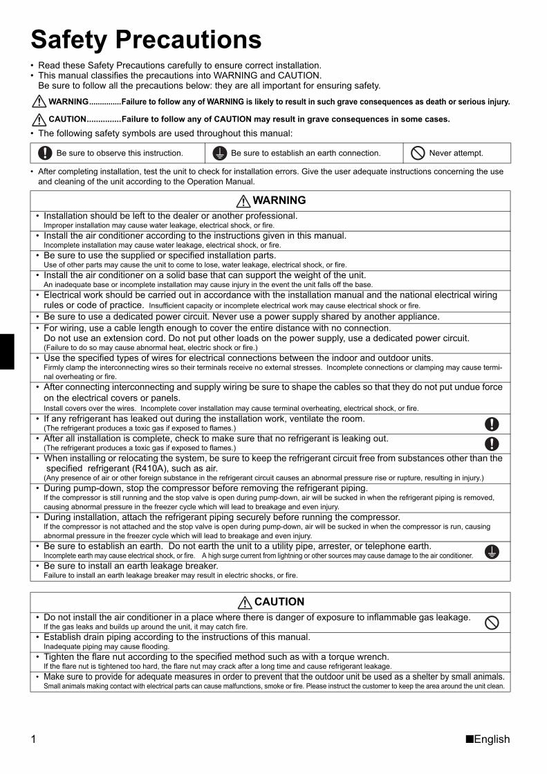
Safety Precautions• Read these Safety Precautions carefully to ensure correct installation.• This manual classifies the precautions into WARNING and CAUTION.
Be sure to follow all the precautions below: they are all important for ensuring safety.
WARNING...............Failure to follow any of WARNING is likely to result in such grave consequences as death or serious injury.
CAUTION...............Failure to follow any of CAUTION may result in grave consequences in some cases.• The following safety symbols are used throughout this manual:
• After completing installation, test the unit to check for installation errors. Give the user adequate instructions concerning the use and cleaning of the unit according to the Operation Manual.
Be sure to observe this instruction. Be sure to establish an earth connection. Never attempt.
WARNING• Installation should be left to the dealer or another professional.
Improper installation may cause water leakage, electrical shock, or fire.• Install the air conditioner according to the instructions given in this manual.
Incomplete installation may cause water leakage, electrical shock, or fire.• Be sure to use the supplied or specified installation parts.
Use of other parts may cause the unit to come to lose, water leakage, electrical shock, or fire.• Install the air conditioner on a solid base that can support the weight of the unit.
An inadequate base or incomplete installation may cause injury in the event the unit falls off the base.• Electrical work should be carried out in accordance with the installation manual and the national electrical wiring
rules or code of practice. Insufficient capacity or incomplete electrical work may cause electrical shock or fire.• Be sure to use a dedicated power circuit. Never use a power supply shared by another appliance.• For wiring, use a cable length enough to cover the entire distance with no connection.
Do not use an extension cord. Do not put other loads on the power supply, use a dedicated power circuit.(Failure to do so may cause abnormal heat, electric shock or fire.)
• Use the specified types of wires for electrical connections between the indoor and outdoor units.Firmly clamp the interconnecting wires so their terminals receive no external stresses. Incomplete connections or clamping may cause termi-nal overheating or fire.
• After connecting interconnecting and supply wiring be sure to shape the cables so that they do not put undue force on the electrical covers or panels.Install covers over the wires. Incomplete cover installation may cause terminal overheating, electrical shock, or fire.
• If any refrigerant has leaked out during the installation work, ventilate the room.(The refrigerant produces a toxic gas if exposed to flames.)
• After all installation is complete, check to make sure that no refrigerant is leaking out.(The refrigerant produces a toxic gas if exposed to flames.)
• When installing or relocating the system, be sure to keep the refrigerant circuit free from substances other than the specified refrigerant (R410A), such as air.
(Any presence of air or other foreign substance in the refrigerant circuit causes an abnormal pressure rise or rupture, resulting in injury.)• During pump-down, stop the compressor before removing the refrigerant piping.
If the compressor is still running and the stop valve is open during pump-down, air will be sucked in when the refrigerant piping is removed, causing abnormal pressure in the freezer cycle which will lead to breakage and even injury.
• During installation, attach the refrigerant piping securely before running the compressor.If the compressor is not attached and the stop valve is open during pump-down, air will be sucked in when the compressor is run, causing abnormal pressure in the freezer cycle which will lead to breakage and even injury.
• Be sure to establish an earth. Do not earth the unit to a utility pipe, arrester, or telephone earth.Incomplete earth may cause electrical shock, or fire. A high surge current from lightning or other sources may cause damage to the air conditioner.
• Be sure to install an earth leakage breaker.Failure to install an earth leakage breaker may result in electric shocks, or fire.
CAUTION• Do not install the air conditioner in a place where there is danger of exposure to inflammable gas leakage.
If the gas leaks and builds up around the unit, it may catch fire.• Establish drain piping according to the instructions of this manual.
Inadequate piping may cause flooding.• Tighten the flare nut according to the specified method such as with a torque wrench.
If the flare nut is tightened too hard, the flare nut may crack after a long time and cause refrigerant leakage.• Make sure to provide for adequate measures in order to prevent that the outdoor unit be used as a shelter by small animals.
Small animals making contact with electrical parts can cause malfunctions, smoke or fire. Please instruct the customer to keep the area around the unit clean.
01_EN_3P188821-1C.fm Page 1 Friday, March 9, 2007 10:52 AM
■English 2
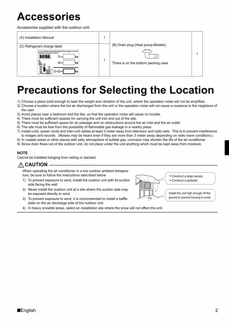
AccessoriesAccessories supplied with the outdoor unit:
Precautions for Selecting the Location1) Choose a place solid enough to bear the weight and vibration of the unit, where the operation noise will not be amplified.2) Choose a location where the hot air discharged from the unit or the operation noise will not cause a nuisance to the neighbors of
the user.3) Avoid places near a bedroom and the like, so that the operation noise will cause no trouble.4) There must be sufficient spaces for carrying the unit into and out of the site.5) There must be sufficient space for air passage and no obstructions around the air inlet and the air outlet.6) The site must be free from the possibility of flammable gas leakage in a nearby place.7) Install units, power cords and inter-unit cables at least 3 meter away from television and radio sets. This is to prevent interference
to images and sounds. (Noises may be heard even if they are more than 3 meter away depending on radio wave conditions.)8) In coastal areas or other places with salty atmosphere of sulfate gas, corrosion may shorten the life of the air conditioner.9) Since drain flows out of the outdoor unit, do not place under the unit anything which must be kept away from moisture.
NOTECannot be installed hanging from ceiling or stacked.
CAUTIONWhen operating the air conditioner in a low outdoor ambient tempera-ture, be sure to follow the instructions described below.1) To prevent exposure to wind, install the outdoor unit with its suction
side facing the wall.2) Never install the outdoor unit at a site where the suction side may
be exposed directly to wind.3) To prevent exposure to wind, it is recommended to install a baffle
plate on the air discharge side of the outdoor unit.4) In heavy snowfall areas, select an installation site where the snow will not affect the unit.
(A) Installation Manual 1
(B) Drain plug (Heat pump-Models)
There is on the bottom packing case.
1
(C) Refrigerant charge label
1
Construct a large canopy.Construct a pedestal.
Install the unit high enough off the ground to prevent burying in snow.
01_EN_3P188821-1C.fm Page 2 Friday, March 9, 2007 10:52 AM
3 ■English
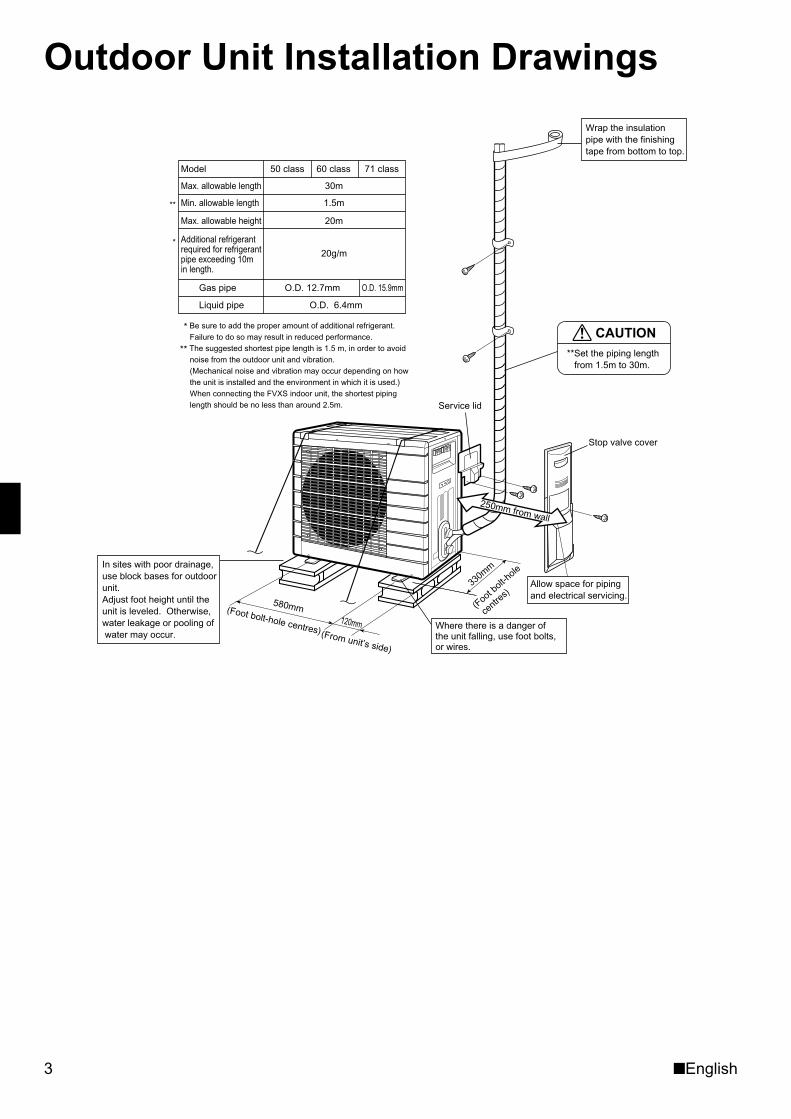
Outdoor Unit Installation Drawings
Model
Max. allowable height
Min. allowable length
Max. allowable length 30m
1.5m
20m
60 class50 class 71 class
Liquid pipe
Gas pipe
O.D. 6.4mm
O.D. 12.7mm O.D. 15.9mm
20g/m
Additional refrigerant required for refrigerant pipe exceeding 10m in length.
**
*
(Foot b
olt-hole
centre
s)330mm
Allow space for piping and electrical servicing.
250mm from wall
CAUTION**Set the piping length
from 1.5m to 30m.
Wrap the insulation pipe with the finishingtape from bottom to top.
Stop valve cover
Service lid
Where there is a danger of the unit falling, use foot bolts, or wires.
In sites with poor drainage, use block bases for outdoor unit. Adjust foot height until the unit is leveled. Otherwise, water leakage or pooling of water may occur.
(Foot bolt-hole centres)
580mm120mm
(From unit’s side)
* Be sure to add the proper amount of additional refrigerant.Failure to do so may result in reduced performance.
** The suggested shortest pipe length is 1.5 m, in order to avoid noise from the outdoor unit and vibration. (Mechanical noise and vibration may occur depending on how the unit is installed and the environment in which it is used.)When connecting the FVXS indoor unit, the shortest piping length should be no less than around 2.5m.
01_EN_3P188821-1C.fm Page 3 Friday, March 9, 2007 10:52 AM
■English 4
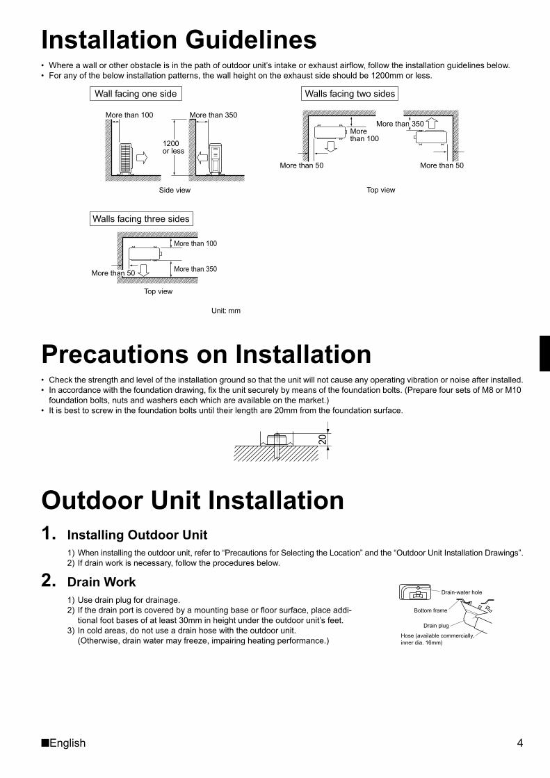
Installation Guidelines• Where a wall or other obstacle is in the path of outdoor unit’s intake or exhaust airflow, follow the installation guidelines below.• For any of the below installation patterns, the wall height on the exhaust side should be 1200mm or less.
Precautions on Installation• Check the strength and level of the installation ground so that the unit will not cause any operating vibration or noise after installed.• In accordance with the foundation drawing, fix the unit securely by means of the foundation bolts. (Prepare four sets of M8 or M10
foundation bolts, nuts and washers each which are available on the market.)• It is best to screw in the foundation bolts until their length are 20mm from the foundation surface.
Outdoor Unit Installation1. Installing Outdoor Unit
1) When installing the outdoor unit, refer to “Precautions for Selecting the Location” and the “Outdoor Unit Installation Drawings”.2) If drain work is necessary, follow the procedures below.
2. Drain Work1) Use drain plug for drainage.2) If the drain port is covered by a mounting base or floor surface, place addi-
tional foot bases of at least 30mm in height under the outdoor unit’s feet.3) In cold areas, do not use a drain hose with the outdoor unit.
(Otherwise, drain water may freeze, impairing heating performance.)
More than 100 More than 350
Side view
1200or less
More than 50 More than 50
More than 350
Top view
More than 100
Top view
Unit: mm
More than 100
More than 350More than 50
Wall facing one side Walls facing two sides
Walls facing three sides
20
Drain-water hole
Bottom frame
Drain plug
Hose (available commercially,inner dia. 16mm)
01_EN_3P188821-1C.fm Page 4 Friday, March 9, 2007 10:52 AM
5 ■English
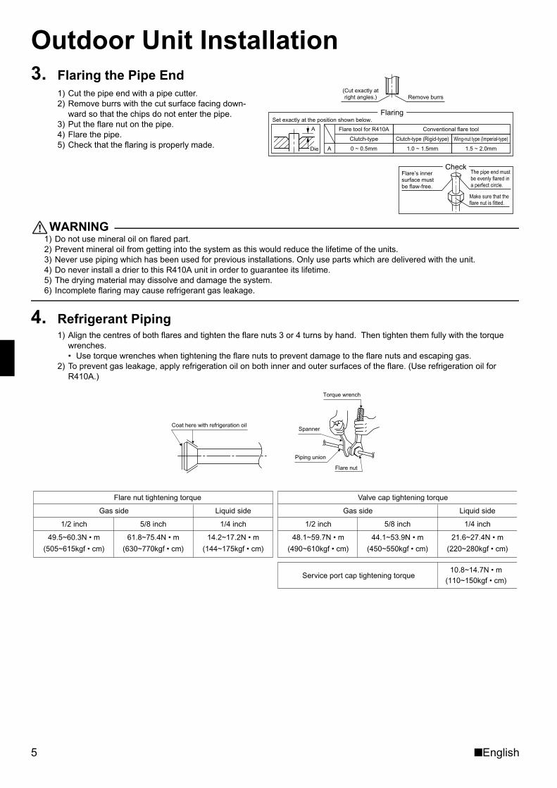
Outdoor Unit Installation3. Flaring the Pipe End
1) Cut the pipe end with a pipe cutter.2) Remove burrs with the cut surface facing down-
ward so that the chips do not enter the pipe.3) Put the flare nut on the pipe.4) Flare the pipe.5) Check that the flaring is properly made.
WARNING1) Do not use mineral oil on flared part.2) Prevent mineral oil from getting into the system as this would reduce the lifetime of the units.3) Never use piping which has been used for previous installations. Only use parts which are delivered with the unit.4) Do never install a drier to this R410A unit in order to guarantee its lifetime.5) The drying material may dissolve and damage the system.6) Incomplete flaring may cause refrigerant gas leakage.
4. Refrigerant Piping1) Align the centres of both flares and tighten the flare nuts 3 or 4 turns by hand. Then tighten them fully with the torque
wrenches.• Use torque wrenches when tightening the flare nuts to prevent damage to the flare nuts and escaping gas.
2) To prevent gas leakage, apply refrigeration oil on both inner and outer surfaces of the flare. (Use refrigeration oil for R410A.)
(Cut exactly at right angles.) Remove burrs
Set exactly at the position shown below.
A
Flaring
Die
CheckFlare’s inner surface must be flaw-free.
The pipe end must be evenly flared in a perfect circle.
Make sure that the flare nut is fitted.
A 0 ~ 0.5mm
Clutch-type
Flare tool for R410A
1.0 ~ 1.5mm
Clutch-type (Rigid-type)
1.5 ~ 2.0mm
Wing-nut type (Imperial-type)
Conventional flare tool
Coat here with refrigeration oil
Torque wrench
Piping union
Flare nut
Spanner
Flare nut tightening torque
Gas side Liquid side
1/2 inch 5/8 inch 1/4 inch
49.5~60.3N • m 61.8~75.4N • m 14.2~17.2N • m
(505~615kgf • cm) (630~770kgf • cm) (144~175kgf • cm)
Valve cap tightening torque
Gas side Liquid side
1/2 inch 5/8 inch 1/4 inch
48.1~59.7N • m 44.1~53.9N • m 21.6~27.4N • m
(490~610kgf • cm) (450~550kgf • cm) (220~280kgf • cm)
Service port cap tightening torque10.8~14.7N • m
(110~150kgf • cm)
01_EN_3P188821-1C.fm Page 5 Friday, March 9, 2007 10:52 AM
■English 6
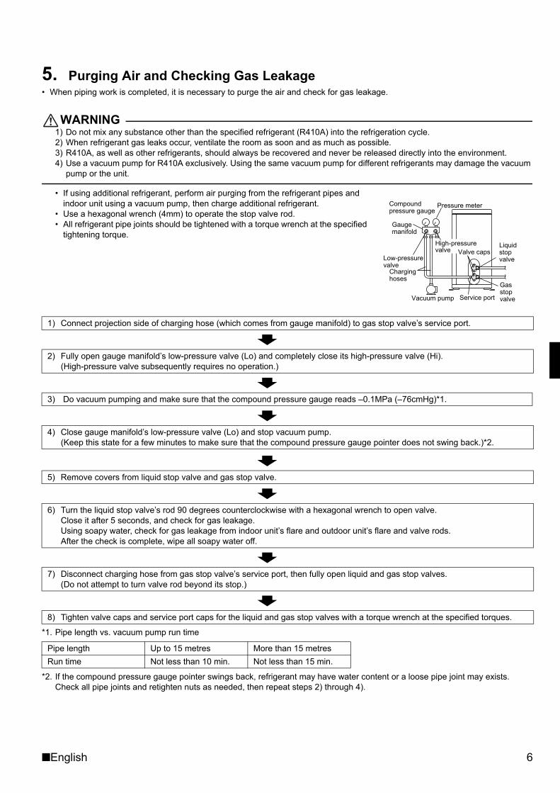
5. Purging Air and Checking Gas Leakage• When piping work is completed, it is necessary to purge the air and check for gas leakage.
WARNING1) Do not mix any substance other than the specified refrigerant (R410A) into the refrigeration cycle.2) When refrigerant gas leaks occur, ventilate the room as soon and as much as possible.3) R410A, as well as other refrigerants, should always be recovered and never be released directly into the environment.4) Use a vacuum pump for R410A exclusively. Using the same vacuum pump for different refrigerants may damage the vacuum
pump or the unit.
• If using additional refrigerant, perform air purging from the refrigerant pipes and indoor unit using a vacuum pump, then charge additional refrigerant.
• Use a hexagonal wrench (4mm) to operate the stop valve rod.• All refrigerant pipe joints should be tightened with a torque wrench at the specified
tightening torque.
*1. Pipe length vs. vacuum pump run time
*2. If the compound pressure gauge pointer swings back, refrigerant may have water content or a loose pipe joint may exists. Check all pipe joints and retighten nuts as needed, then repeat steps 2) through 4).
1) Connect projection side of charging hose (which comes from gauge manifold) to gas stop valve’s service port.
2) Fully open gauge manifold’s low-pressure valve (Lo) and completely close its high-pressure valve (Hi). (High-pressure valve subsequently requires no operation.)
3) Do vacuum pumping and make sure that the compound pressure gauge reads –0.1MPa (–76cmHg)*1.
4) Close gauge manifold’s low-pressure valve (Lo) and stop vacuum pump. (Keep this state for a few minutes to make sure that the compound pressure gauge pointer does not swing back.)*2.
5) Remove covers from liquid stop valve and gas stop valve.
6) Turn the liquid stop valve’s rod 90 degrees counterclockwise with a hexagonal wrench to open valve.Close it after 5 seconds, and check for gas leakage.Using soapy water, check for gas leakage from indoor unit’s flare and outdoor unit’s flare and valve rods.After the check is complete, wipe all soapy water off.
7) Disconnect charging hose from gas stop valve’s service port, then fully open liquid and gas stop valves.(Do not attempt to turn valve rod beyond its stop.)
8) Tighten valve caps and service port caps for the liquid and gas stop valves with a torque wrench at the specified torques.
Pipe length Up to 15 metres More than 15 metresRun time Not less than 10 min. Not less than 15 min.
Gauge manifold
Compound pressure gauge
Pressure meter
Low-pressure valve
High-pressure valve
Charging hoses
Vacuum pump
Valve caps
Service port
Liquid stop valve
Gas stop valve
01_EN_3P188821-1C.fm Page 6 Friday, March 9, 2007 10:52 AM
7 ■English
Outdoor Unit Installation6. Refilling the Refrigerant
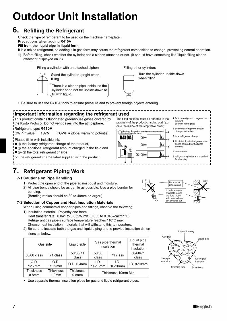
Check the type of refrigerant to be used on the machine nameplate.Precautions when adding R410AFill from the liquid pipe in liquid form.It is a mixed refrigerant, so adding it in gas form may cause the refrigerant composition to change, preventing normal operation.1) Before filling, check whether the cylinder has a siphon attached or not. (It should have something like “liquid filling siphon
attached” displayed on it.)
• Be sure to use the R410A tools to ensure pressure and to prevent foreign objects entering.
7. Refrigerant Piping Work7-1 Cautions on Pipe Handling
1) Protect the open end of the pipe against dust and moisture.2) All pipe bends should be as gentle as possible. Use a pipe bender for
bending.(Bending radius should be 30 to 40mm or larger.)
7-2 Selection of Copper and Heat Insulation MaterialsWhen using commercial copper pipes and fittings, observe the following:1) Insulation material: Polyethylene foam
Heat transfer rate: 0.041 to 0.052W/mK (0.035 to 0.045kcal/mh°C)Refrigerant gas pipe’s surface temperature reaches 110°C max.Choose heat insulation materials that will withstand this temperature.
2) Be sure to insulate both the gas and liquid piping and to provide insulation dimen-sions as below.
• Use separate thermal insulation pipes for gas and liquid refrigerant pipes.
Gas side Liquid side Gas pipe thermal insulation
Liquid pipe thermal
insulation
50/60 class 71 class 50/60/71 class
50/60 class 71 class 50/60/71
classO.D.
12.7mmO.D.
15.9mm O.D. 6.4mm I.D. 14-16mm
I.D. 16-20mm I.D. 8-10mm
Thickness 0.8mm
Thickness 1.0mm
Thickness 0.8mm Thickness 10mm Min.
Filling a cylinder with an attached siphon
Stand the cylinder upright when filling.
There is a siphon pipe inside, so the cylinder need not be upside-down to fill with liquid.
Filling other cylinders
Turn the cylinder upside-down when filling.
3
56
2
1
4
Please fill in with indelible ink, � 1 the factory refrigerant charge of the product, � 2 the additional refrigerant amount charged in the field and� 1 + 2 the total refrigerant charge on the refrigerant charge label supplied with the product.
Important information regarding the refrigerant usedThis product contains fluorinated greenhouse gases covered by the Kyoto Protocol. Do not vent gases into the atmosphere.
Refrigerant type: R410AGWP(1) value: 1975 (1) GWP = global warming potential
1 factory refrigerant charge of the product: see unit name plate
2 additional refrigerant amount charged in the field
3 total refrigerant charge
4 Contains fluorinated greenhouse gases covered by the Kyoto Protocol
5 outdoor unit
6 refrigerant cylinder and manifold for charging
The filled out label must be adhered in the proximity of the product charging port (e.g. onto the inside of the stop valve cover).
Wall
If no flare cap is available, cover the flare mouth with tape to keep dirt or water out.
Be sure to place a cap.
Rain
Gas pipeLiquid pipe
Gas pipe insulation
Liquid pipe insulation
Finishing tape Drain hose
Inter-unit wiring
01_EN_3P188821-1C.fm Page 7 Friday, March 9, 2007 10:52 AM
■English 8
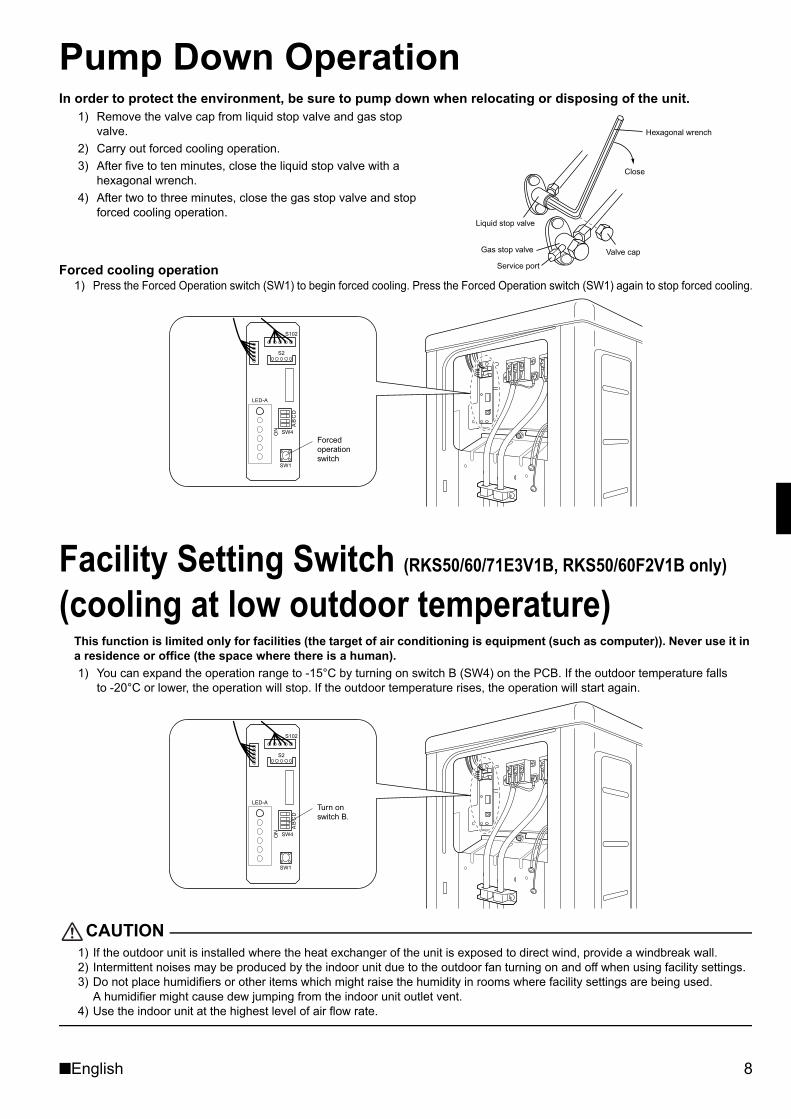
Pump Down OperationIn order to protect the environment, be sure to pump down when relocating or disposing of the unit.
1) Remove the valve cap from liquid stop valve and gas stop valve.
2) Carry out forced cooling operation.3) After five to ten minutes, close the liquid stop valve with a
hexagonal wrench.4) After two to three minutes, close the gas stop valve and stop
forced cooling operation.
Forced cooling operation1) Press the Forced Operation switch (SW1) to begin forced cooling. Press the Forced Operation switch (SW1) again to stop forced cooling.
Facility Setting Switch (RKS50/60/71E3V1B, RKS50/60F2V1B only) (cooling at low outdoor temperature)
This function is limited only for facilities (the target of air conditioning is equipment (such as computer)). Never use it in a residence or office (the space where there is a human).1) You can expand the operation range to -15°C by turning on switch B (SW4) on the PCB. If the outdoor temperature falls
to -20°C or lower, the operation will stop. If the outdoor temperature rises, the operation will start again.
CAUTION1) If the outdoor unit is installed where the heat exchanger of the unit is exposed to direct wind, provide a windbreak wall.2) Intermittent noises may be produced by the indoor unit due to the outdoor fan turning on and off when using facility settings.3) Do not place humidifiers or other items which might raise the humidity in rooms where facility settings are being used.
A humidifier might cause dew jumping from the indoor unit outlet vent.4) Use the indoor unit at the highest level of air flow rate.
Gas stop valve Valve cap
Hexagonal wrench
Close
Liquid stop valve
Service port
LED-A
SW4ON
AB
CD
S102
SW1
S2
Forced operation switch
LED-A
SW4ON
AB
CD
S102
SW1
S2
Turn on switch B.
01_EN_3P188821-1C.fm Page 8 Friday, March 9, 2007 10:52 AM
9 ■English
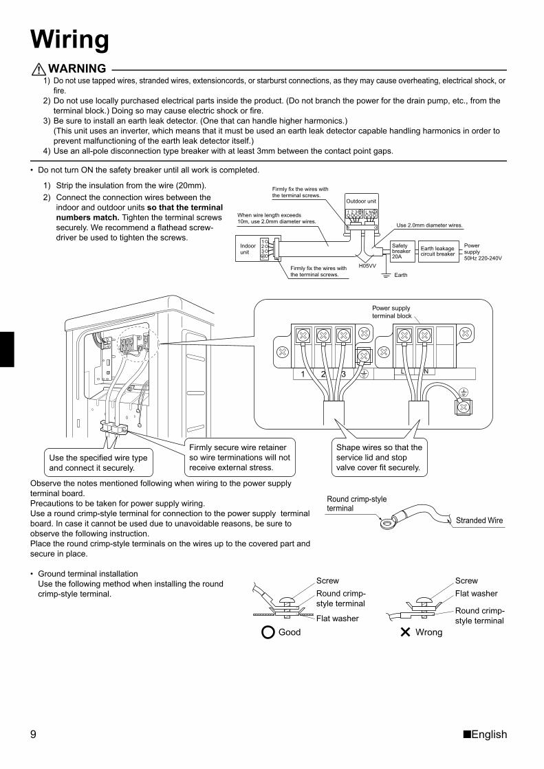
WiringWARNING
1) Do not use tapped wires, stranded wires, extensioncords, or starburst connections, as they may cause overheating, electrical shock, or fire.
2) Do not use locally purchased electrical parts inside the product. (Do not branch the power for the drain pump, etc., from the terminal block.) Doing so may cause electric shock or fire.
3) Be sure to install an earth leak detector. (One that can handle higher harmonics.)(This unit uses an inverter, which means that it must be used an earth leak detector capable handling harmonics in order to prevent malfunctioning of the earth leak detector itself.)
4) Use an all-pole disconnection type breaker with at least 3mm between the contact point gaps.
• Do not turn ON the safety breaker until all work is completed.
1) Strip the insulation from the wire (20mm).2) Connect the connection wires between the
indoor and outdoor units so that the terminal numbers match. Tighten the terminal screws securely. We recommend a flathead screw-driver be used to tighten the screws.
Observe the notes mentioned following when wiring to the power supply terminal board.Precautions to be taken for power supply wiring. Use a round crimp-style terminal for connection to the power supply terminal board. In case it cannot be used due to unavoidable reasons, be sure to observe the following instruction. Place the round crimp-style terminals on the wires up to the covered part and secure in place.
• Ground terminal installation Use the following method when installing the round crimp-style terminal.
123
1 2 3 L N
Safety breaker 20A
Earth leakage circuit breaker
Earth
When wire length exceeds 10m, use 2.0mm diameter wires.
H05VV
Firmly fix the wires with the terminal screws.
Outdoor unit
Indoor unit
Powersupply50Hz 220-240V
Firmly fix the wires with the terminal screws.
Use 2.0mm diameter wires.
Use the specified wire type and connect it securely.
Firmly secure wire retainer so wire terminations will not receive external stress.
Power supply terminal block
L N1 2 3
Shape wires so that the service lid and stop valve cover fit securely.
Stranded Wire
Round crimp-styleterminal
Good Wrong
Round crimp-style terminal
Flat washer
Screw
Flat washer
Round crimp-style terminal
Screw
01_EN_3P188821-1C.fm Page 9 Friday, March 9, 2007 10:52 AM
■English 10
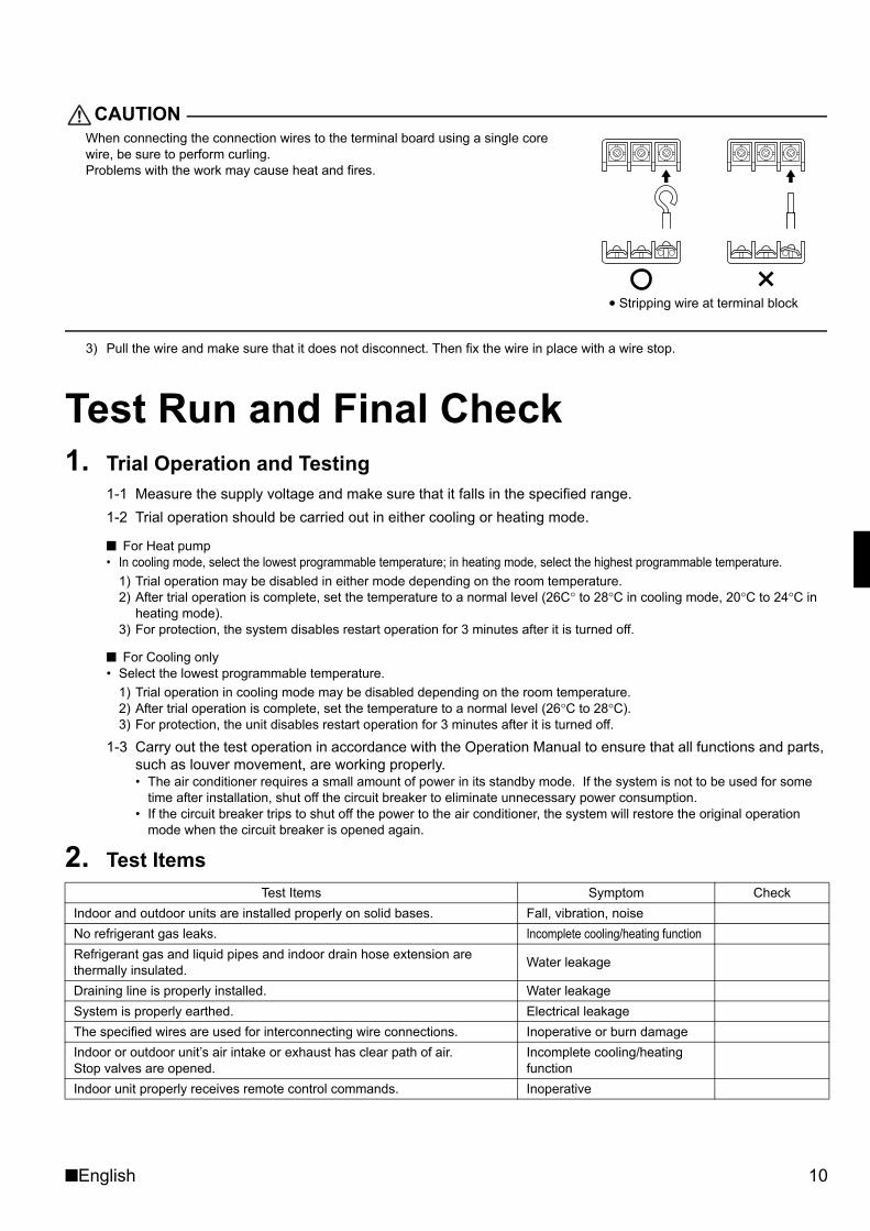
CAUTIONWhen connecting the connection wires to the terminal board using a single core wire, be sure to perform curling. Problems with the work may cause heat and fires.
3) Pull the wire and make sure that it does not disconnect. Then fix the wire in place with a wire stop.
Test Run and Final Check1. Trial Operation and Testing
1-1 Measure the supply voltage and make sure that it falls in the specified range.1-2 Trial operation should be carried out in either cooling or heating mode.
■ For Heat pump• In cooling mode, select the lowest programmable temperature; in heating mode, select the highest programmable temperature.
1) Trial operation may be disabled in either mode depending on the room temperature.2) After trial operation is complete, set the temperature to a normal level (26C° to 28°C in cooling mode, 20°C to 24°C in
heating mode).3) For protection, the system disables restart operation for 3 minutes after it is turned off.
■ For Cooling only• Select the lowest programmable temperature.
1) Trial operation in cooling mode may be disabled depending on the room temperature.2) After trial operation is complete, set the temperature to a normal level (26°C to 28°C).3) For protection, the unit disables restart operation for 3 minutes after it is turned off.
1-3 Carry out the test operation in accordance with the Operation Manual to ensure that all functions and parts, such as louver movement, are working properly.• The air conditioner requires a small amount of power in its standby mode. If the system is not to be used for some
time after installation, shut off the circuit breaker to eliminate unnecessary power consumption.• If the circuit breaker trips to shut off the power to the air conditioner, the system will restore the original operation
mode when the circuit breaker is opened again.
2. Test Items Test Items Symptom Check
Indoor and outdoor units are installed properly on solid bases. Fall, vibration, noiseNo refrigerant gas leaks. Incomplete cooling/heating functionRefrigerant gas and liquid pipes and indoor drain hose extension are thermally insulated. Water leakage
Draining line is properly installed. Water leakageSystem is properly earthed. Electrical leakageThe specified wires are used for interconnecting wire connections. Inoperative or burn damageIndoor or outdoor unit’s air intake or exhaust has clear path of air.Stop valves are opened.
Incomplete cooling/heating function
Indoor unit properly receives remote control commands. Inoperative
Stripping wire at terminal block
01_EN_3P188821-1C.fm Page 10 Friday, March 9, 2007 10:52 AM
(0704) HT3P188821-1C M06B069CTwo-dimensional bar code is a codefor manufacturing.
00_CV_3P188821-1C.fm Page 2 Friday, March 9, 2007 10:41 AM