Basic Electronics How do I hook up a ________ to my ________circuit?
Upload
ahmedkhattakCategory
view
20download
1description
Bilal Ashraf Awan - Basic Electronics 1
BASIC ELECTRONICSReview of Basic Concepts
Bilal Ashraf Awan - Basic Electronics 2
RESISTANCE
Bilal Ashraf Awan - Basic Electronics 3
Resistance• The property of a substance due to which it opposes the
flow of electricity (i.e. electrons) through it.
• The unit of resistance is ohm. Symbol is Ω.
• OHM• A conductor is said to have a resistance of one ohm if it permits
one ampere current to flow through it when one volt is applied across its terminals.
Bilal Ashraf Awan - Basic Electronics 4
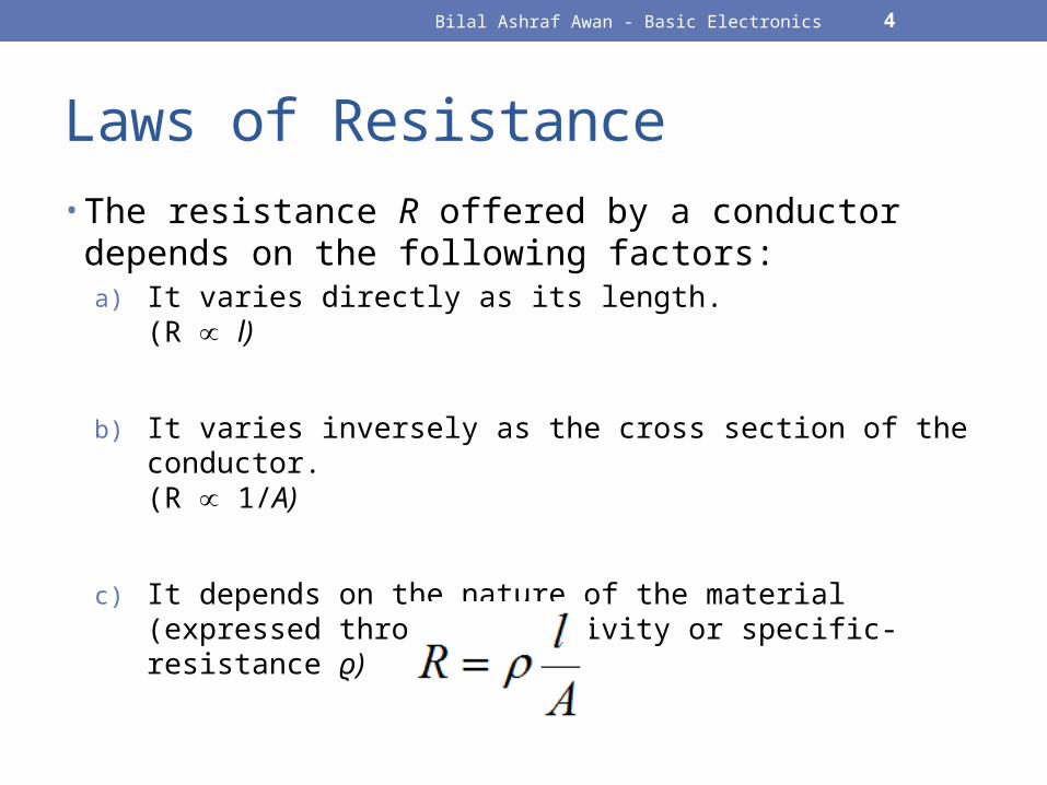
Laws of Resistance• The resistance R offered by a conductor depends on the
following factors:a) It varies directly as its length.
(R ∝ l)
b) It varies inversely as the cross section of the conductor. (R 1/∝ A)
c) It depends on the nature of the material (expressed through resistivity or specific-resistance ϱ)

Bilal Ashraf Awan - Basic Electronics 5
Resistivity / Specific Resistance ϱ • The resistance between the opposite faces of a meter
cube of that material.
• Unit: ohm-meter
R = ϱ
Current
1 m3
Bilal Ashraf Awan - Basic Electronics 6
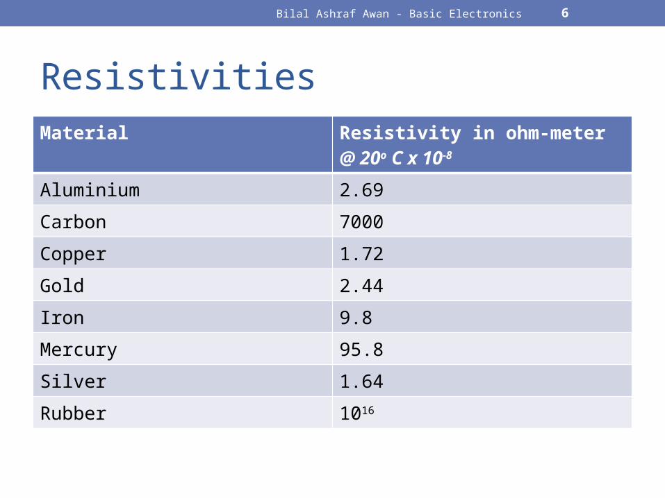
ResistivitiesMaterial Resistivity in ohm-meter
@ 20o C x 10-8
Aluminium 2.69
Carbon 7000
Copper 1.72
Gold 2.44
Iron 9.8
Mercury 95.8
Silver 1.64
Rubber 1016
Bilal Ashraf Awan - Basic Electronics 7
Example:• The resistance of a Cu wire 200 m long is 21 Ω. If its
thickness is 0.44mm, calculate its specific resistance.
Bilal Ashraf Awan - Basic Electronics 8
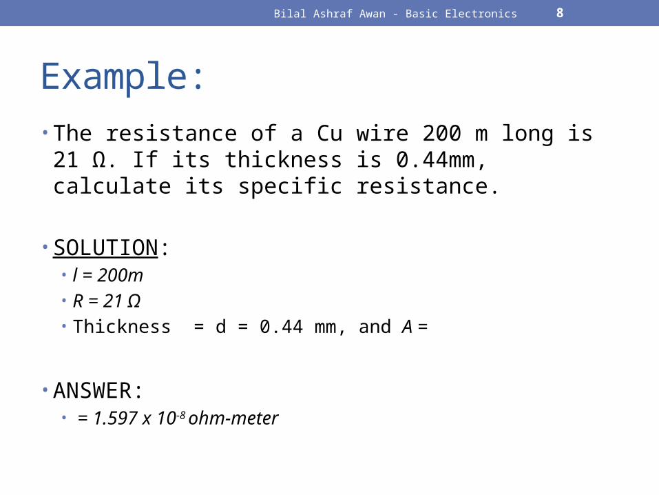
Example:• The resistance of a Cu wire 200 m long is 21 Ω. If its
thickness is 0.44mm, calculate its specific resistance.
• SOLUTION:• l = 200m• R = 21 Ω• Thickness = d = 0.44 mm, and A =
• ANSWER:• = 1.597 x 10⁻⁸ ohm-meter
Bilal Ashraf Awan - Basic Electronics 9
OHM’S LAW
Bilal Ashraf Awan - Basic Electronics 10
Ohm’s Law• The ratio of potential difference V between any two points
of a conductor to the current I flowing between them is constant, provided the temperature of the conductor does not change.
• In other words, current is directly proportional to voltage and inversely proportional to resistance.
Bilal Ashraf Awan - Basic Electronics 11
Example
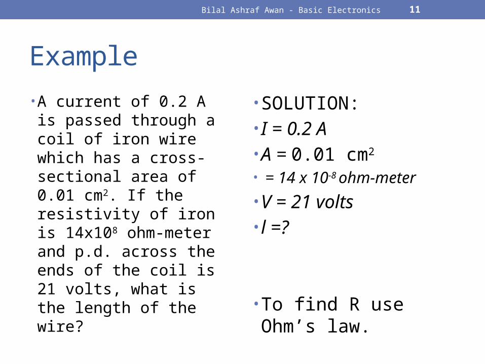
• A current of 0.2 A is passed through a coil of iron wire which has a cross-sectional area of 0.01 cm2. If the resistivity of iron is 14x108 ohm-meter and p.d. across the ends of the coil is 21 volts, what is the length of the wire?
• SOLUTION:• I = 0.2 A• A = 0.01 cm2
• = 14 x 10-8 ohm-meter
• V = 21 volts• l =?
• To find R use Ohm’s law.
Bilal Ashraf Awan - Basic Electronics 12
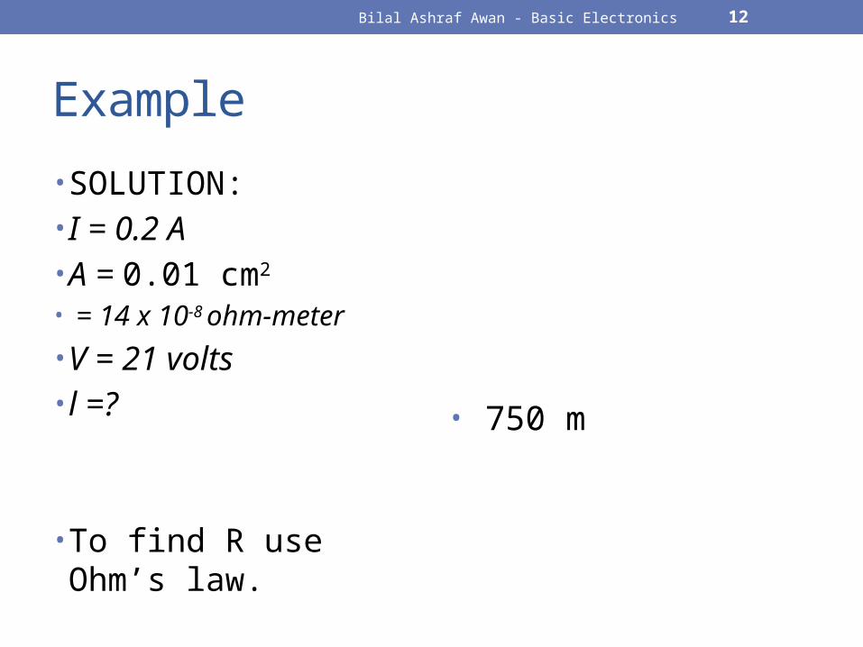
Example
• SOLUTION:• I = 0.2 A• A = 0.01 cm2
• = 14 x 10-8 ohm-meter
• V = 21 volts• l =?
• To find R use Ohm’s law.
• 750 m
Bilal Ashraf Awan - Basic Electronics 13
RESISTANCE IN SERIES & PARALLEL
Bilal Ashraf Awan - Basic Electronics 14
Resistance in Series• Joined end to end, in series.• Current is the same in all resistors.• Voltage is different.

Bilal Ashraf Awan - Basic Electronics 15
Resistance in Parallel• Joined in parallel.• Current is different.• Voltage is same across all resistors.
Bilal Ashraf Awan - Basic Electronics 16
Equivalent Resistance• Resistors in Series
• Resistors in Parallel
Bilal Ashraf Awan - Basic Electronics 17
CONVENTIONAL & ELECTRON FLOW
Bilal Ashraf Awan - Basic Electronics 18
Fluid Theory of Electricity• Franklin (1750) proposed a fluid theory of electricity
• Electricity as an invisible fluid
• Positive Charge: If a body has more than normal share of fluid• Negative Charge: If a body has less than normal share of fluid• Current flows from positive (excess) to negative (deficiency)
Bilal Ashraf Awan - Basic Electronics 19
Conventional Current and Fluid Theory
• Conventional Current: • Current flows from positive to negative as depicted by Fluid Theory
Bilal Ashraf Awan - Basic Electronics 20
The Electron
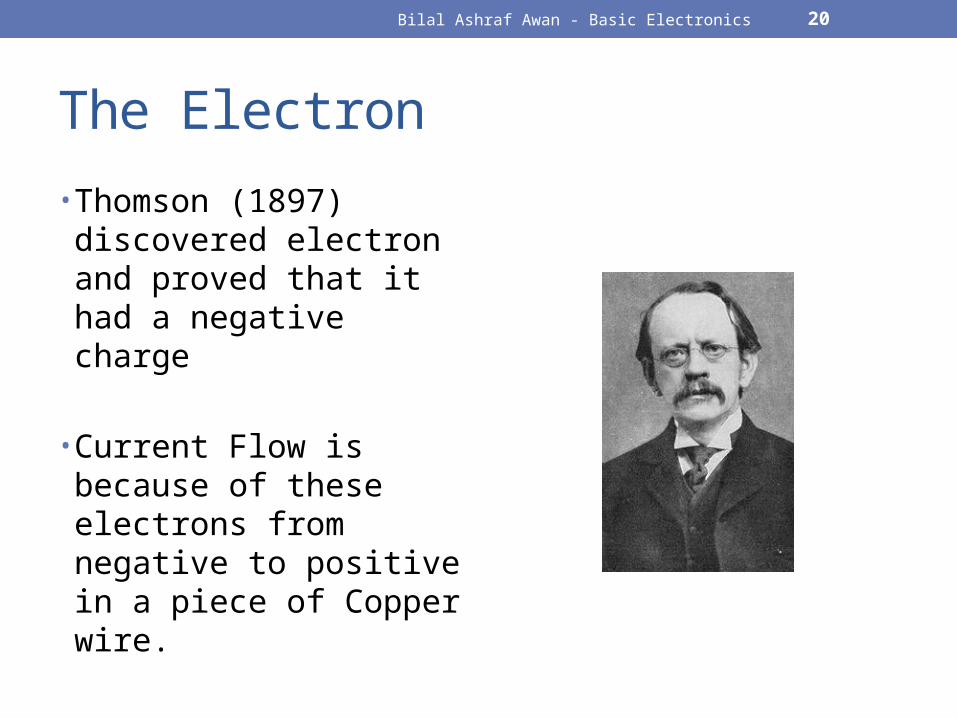
• Thomson (1897) discovered electron and proved that it had a negative charge
• Current Flow is because of these electrons from negative to positive in a piece of Copper wire.
Bilal Ashraf Awan - Basic Electronics 21
Conventional or Electron Flow?• Either flow is valid for understanding electric current.
Bilal Ashraf Awan - Basic Electronics 22
VOLTAGE SOURCES
Bilal Ashraf Awan - Basic Electronics 23
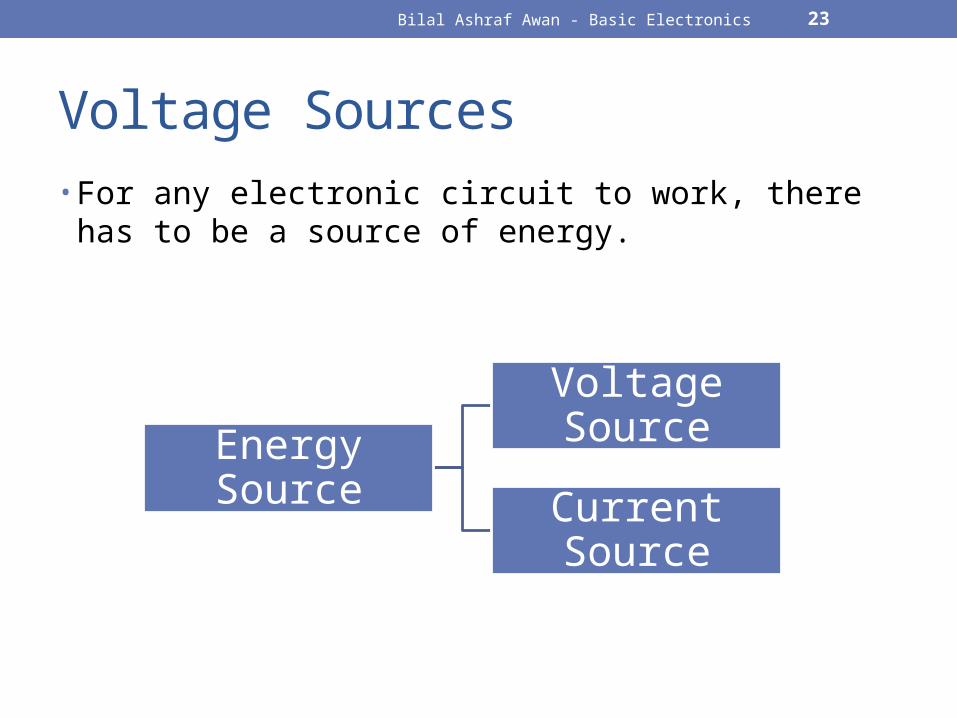
Voltage Sources• For any electronic circuit to work, there has to be a source
of energy.
Energy Source
Voltage Source
Current Source
Bilal Ashraf Awan - Basic Electronics 24
Voltage Source
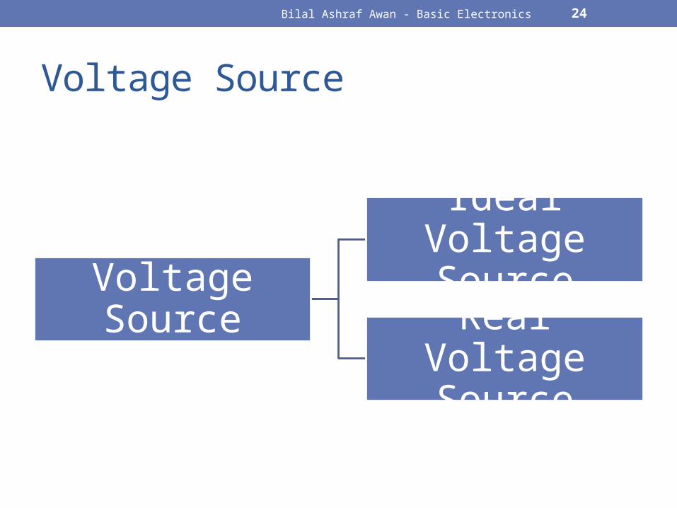
Voltage Source
Ideal Voltage Source
Real Voltage Source
Bilal Ashraf Awan - Basic Electronics 25
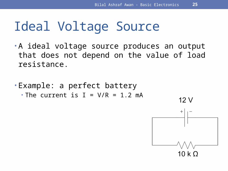
Ideal Voltage Source• A ideal voltage source produces an output that does not
depend on the value of load resistance.
• Example: a perfect battery• The current is I = V/R = 1.2 mA
Bilal Ashraf Awan - Basic Electronics 26
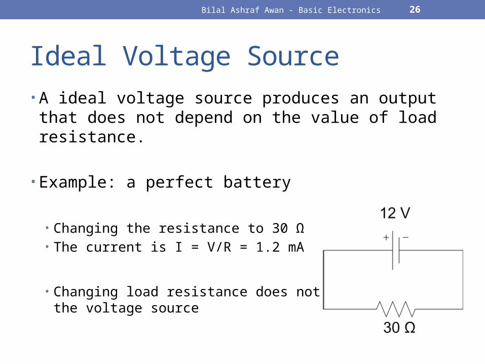
Ideal Voltage Source• A ideal voltage source produces an output that does not
depend on the value of load resistance.
• Example: a perfect battery
• Changing the resistance to 30 Ω• The current is I = V/R = 1.2 mA
• Changing load resistance does not effect the voltage source
Bilal Ashraf Awan - Basic Electronics 27
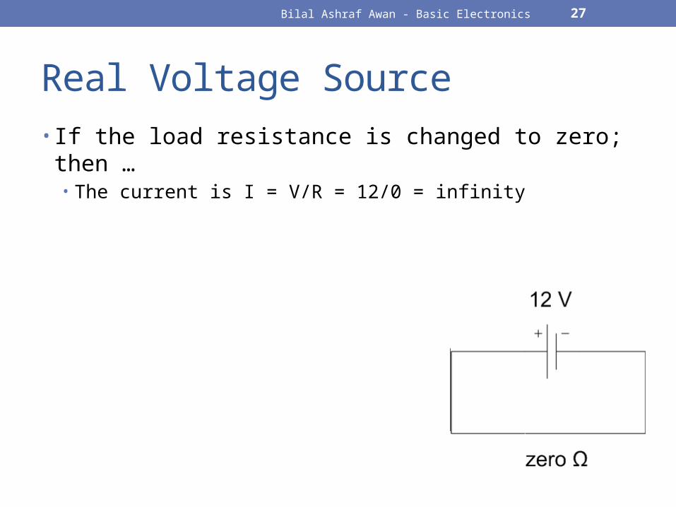
Real Voltage Source• If the load resistance is changed to zero; then …
• The current is I = V/R = 12/0 = infinity
Bilal Ashraf Awan - Basic Electronics 28
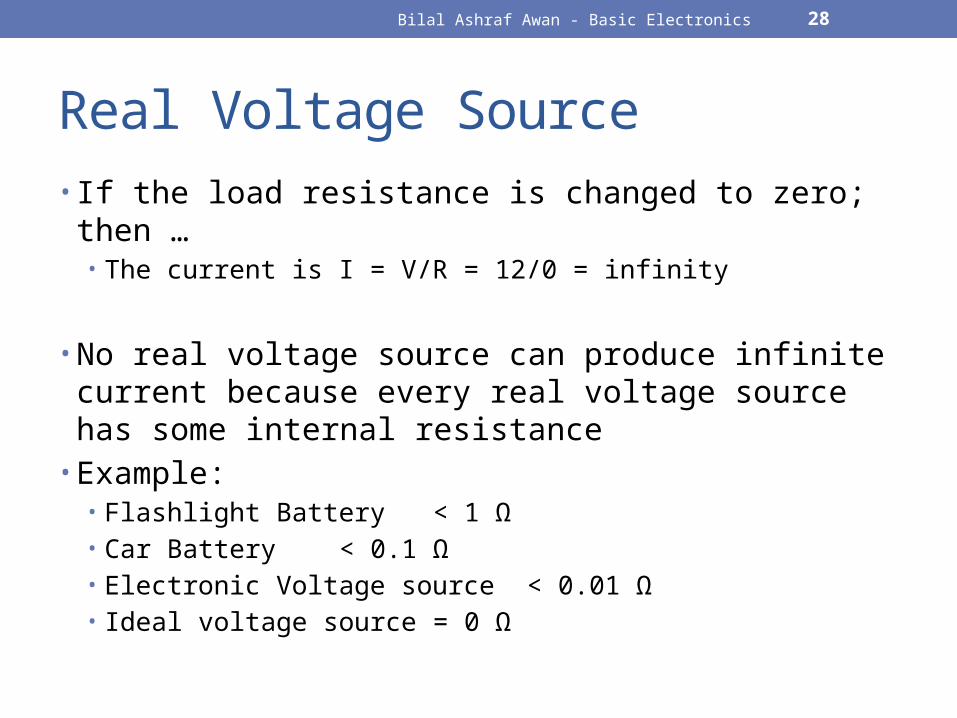
Real Voltage Source• If the load resistance is changed to zero; then …
• The current is I = V/R = 12/0 = infinity
• No real voltage source can produce infinite current because every real voltage source has some internal resistance
• Example:• Flashlight Battery < 1 Ω• Car Battery < 0.1 Ω• Electronic Voltage source < 0.01 Ω• Ideal voltage source = 0 Ω
Bilal Ashraf Awan - Basic Electronics 29
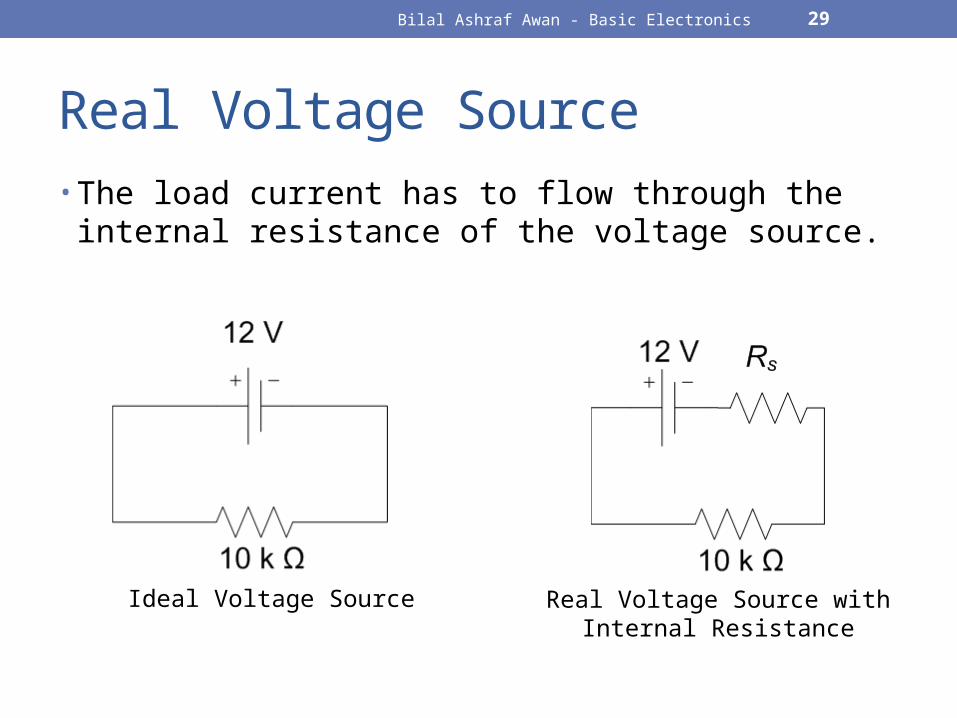
Real Voltage Source• The load current has to flow through the internal
resistance of the voltage source.
Ideal Voltage Source Real Voltage Source with Internal Resistance
Bilal Ashraf Awan - Basic Electronics 30
Stiff Voltage Source
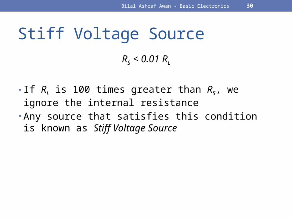
RS < 0.01 RL
• If RL is 100 times greater than RS, we ignore the internal resistance
• Any source that satisfies this condition is known as Stiff Voltage Source
Bilal Ashraf Awan - Basic Electronics 31
Stiff Voltage Source• Example:• Suppose a voltage source has an ideal voltage of 15 V
and an internal resistance of 0.2 Ω. For what voltage of load resistance will the voltage source appear stiff?
• SOLUTION:• For a voltage source to be stiff, the following condition
applies
RS < 0.01 RL
• Multiply RL by 100, we get
• RL = 100(0.2 Ω) = 20 Ω.
• ANSWER: As long as load resistance is greater than 20 Ω, the voltage source is stiff.
Bilal Ashraf Awan - Basic Electronics 32
CURRENT SOURCES
Bilal Ashraf Awan - Basic Electronics 33
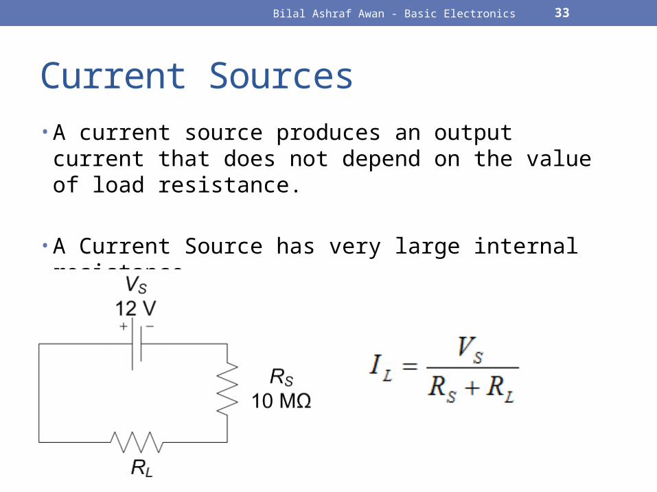
Current Sources• A current source produces an output current that does not
depend on the value of load resistance.
• A Current Source has very large internal resistance.•
Bilal Ashraf Awan - Basic Electronics 34
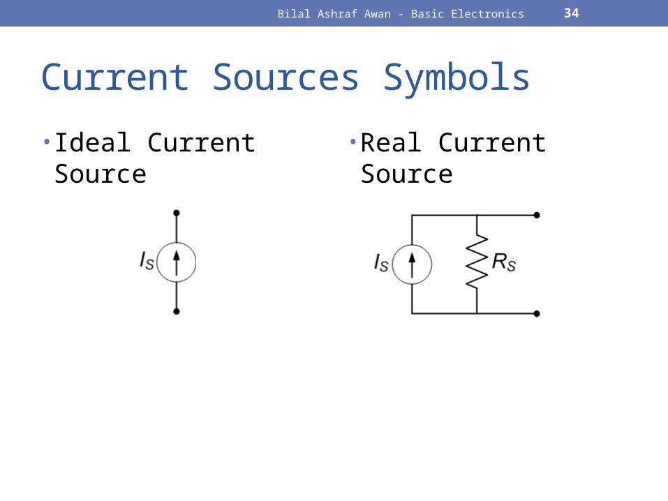
Current Sources Symbols
• Ideal Current Source • Real Current Source
Bilal Ashraf Awan - Basic Electronics 35
Stiff Current Source• For a current source to be stiff, the following condition
applies:• RS > 100 RL
Bilal Ashraf Awan - Basic Electronics 36
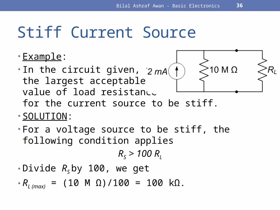
Stiff Current Source• Example:• In the circuit given, find out
the largest acceptable value of load resistance for the current source to be stiff.
• SOLUTION:• For a voltage source to be stiff, the following condition
applies
RS > 100 RL
• Divide RS by 100, we get
• RL (max) = (10 M Ω)/100 = 100 kΩ.
Bilal Ashraf Awan - Basic Electronics 37
NETWORK LAWS & THEOREMS
Bilal Ashraf Awan - Basic Electronics 38
Kirchhoff’s Laws• Kirchhoff’s Current Laws (KCL) / Point Law
• The algebraic sum of the currents meeting at a point (or junction) is zero.
• Kirchhoff’s Voltage Laws (KVL) / Mesh Law• The algebraic sum of the product of current and resistance in each
of the conductors in any closed mesh (or path) in a network plus the algebraic sum of the e.m.f.s in that path) is zero.
Bilal Ashraf Awan - Basic Electronics 39
THEVENIN’S THEOREM
Bilal Ashraf Awan - Basic Electronics 40
Thevenin’s Theorem• Any network, when viewed from its any two terminal points,
can be replaced by a single voltage source (Vth)in series with a single resistance (Rth).
• Thevenin’s Voltage• Voltage across the load terminals when the load resistor is open.
• VTH = VOC
• Thevenin’s Resistance• The resistance that an ohm-meter measures across the load terminals
when all sources are reduced to zero and the load resistor is open.• RTH = ROC
• To zero a voltage source, replace it by a short.
Bilal Ashraf Awan - Basic Electronics 41
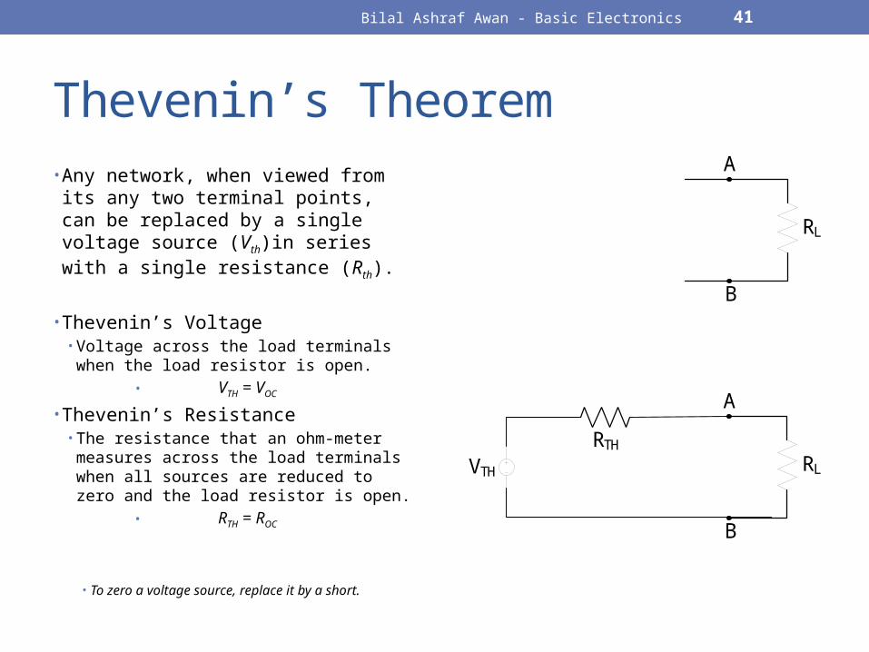
Thevenin’s Theorem• Any network, when viewed from its any
two terminal points, can be replaced by a single voltage source (Vth)in series with a single resistance (Rth).
• Thevenin’s Voltage• Voltage across the load terminals when
the load resistor is open.• VTH = VOC
• Thevenin’s Resistance• The resistance that an ohm-meter
measures across the load terminals when all sources are reduced to zero and the load resistor is open.
• RTH = ROC
• To zero a voltage source, replace it by a short.
RL
A
B
RL
A
B
RTHVTH
Bilal Ashraf Awan - Basic Electronics 42
Example-1 (Thevenin’s Th.)