0 RS-485 MODBUS COMM. D. Digital Trip Relay 6. IO (Input-Output) Port Profibus -DP COMM. Digital...
8
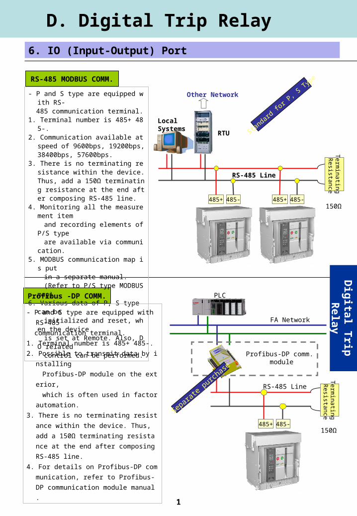
1 RS-485 MODBUS COMM. D. Digital Trip Relay 6. IO (Input-Output) Port Profibus -DP COMM. Digital Trip Relay - P and S type are equipped w ith RS- 485 communication terminal. 1. Terminal number is 485+ 48 5-. 2. Communication available at speed of 9600bps, 19200bps, 38400bps, 57600bps. 3. There is no terminating re sistance within the device. Thus, add a 150Ω terminatin g resistance at the end aft er composing RS-485 line. 4. Monitoring all the measure ment item and recording elements of P/S type are available via communi cation. 5. MODBUS communication map i s put in a separate manual. (Refer to P/S type MODBUS map) 6. Various data of P, S type can be initialized and reset, wh en the device is set at Remote. Also, D O related control can be performed. 150Ω Standard for P, S Type RS-485 Line 485+ 485- Local Systems Other Network RTU 485+ 485- Terminating Resistance - P and S type are equipped with RS-485 communication terminal. 1. Terminal number is 485+ 485-. 2. Possible to transmit data by i nstalling Profibus-DP module on the ext erior, which is often used in factor automation. 3. There is no terminating resist ance within the device. Thus, add a 150Ω terminating resista nce at the end after composing RS-485 line. 4. For details on Profibus-DP com munication, refer to Profibus- DP communication module manual . 150Ω RS-485 Line Profibus-DP comm. module PLC FA Network 485+ 485- Sep arate purc hase Terminating Resistance
-
Upload
wilfrid-smith -
Category
Documents
-
view
224 -
download
0
Transcript of 0 RS-485 MODBUS COMM. D. Digital Trip Relay 6. IO (Input-Output) Port Profibus -DP COMM. Digital...
1
RS-485 MODBUS COMM.
D. Digital Trip Relay
6. IO (Input-Output) Port
Profibus -DP COMM.
Dig
ital Trip
Relay
- P and S type are equipped with RS- 485 communication terminal.1. Terminal number is 485+ 485-. 2. Communication available at speed of
9600bps, 19200bps, 38400bps, 57600bps.
3. There is no terminating resistance within the device. Thus, add a 150Ω terminating resistance at the end after composing RS-485 line.
4. Monitoring all the measurement item and recording elements of P/S type are available via communication. 5. MODBUS communication map is put in a separate manual. (Refer to P/S type MODBUS map)6. Various data of P, S type can be initialized and reset, when the device is set at Remote. Also, DO related control can be performed.
150Ω
Standard fo
r P, S
Typ
e
RS-485 Line
485+ 485-
Local Systems
Other Network
RTU
485+ 485-
Te
rmin
ating
Resista
nce
- P and S type are equipped with RS-485
communication terminal.
1. Terminal number is 485+ 485-.
2. Possible to transmit data by installing
Profibus-DP module on the exterior,
which is often used in factor automation.
3. There is no terminating resistance within t
he device. Thus, add a 150Ω terminating
resistance at the end after composing RS
-485 line.
4. For details on Profibus-DP communication
, refer to Profibus-DP communication mo
dule manual.150Ω
RS-485 Line
Profibus-DP comm. module
PLC
FA Network
485+ 485-
Separate purch
ase
Te
rmin
ating
Resista
nce
2
82.5
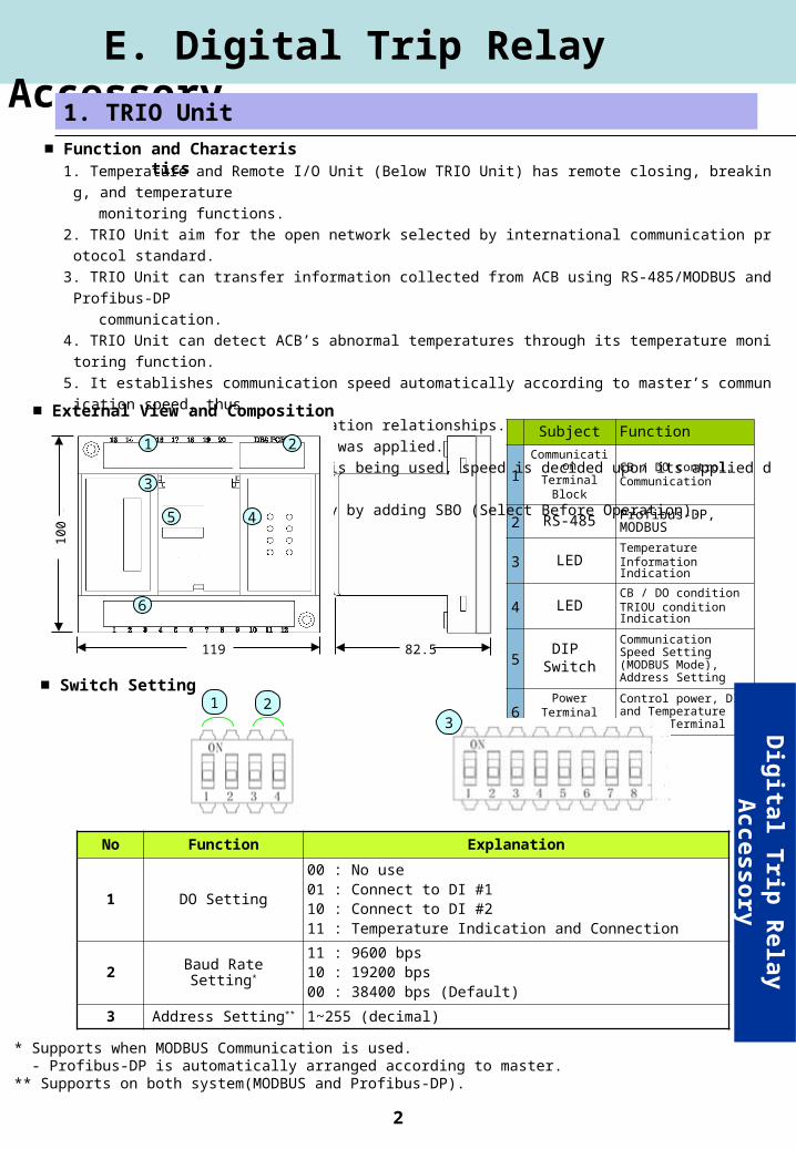
Subject Function
1Communication
TerminalBlock
CB / DO control,Communication
2 RS-485 Profibus-DP, MODBUS
3 LED TemperatureInformation Indication
4 LEDCB / DO conditionTRIOU condition Indication
5DIP
Switch
Communication Speed Setting (MODBUS Mode), Address Setting
6Power
Terminal Block
Control power, DI, and Temperature Sensor Terminal
External View and Composition
1. Temperature and Remote I/O Unit (Below TRIO Unit) has remote closing, breaking, and temperature
monitoring functions.
2. TRIO Unit aim for the open network selected by international communication protocol standard.
3. TRIO Unit can transfer information collected from ACB using RS-485/MODBUS and Profibus-DP
communication.
4. TRIO Unit can detect ACB’s abnormal temperatures through its temperature monitoring function.
5. It establishes communication speed automatically according to master’s communication speed, thus
maintain flexible communication relationships.
- But, only when Profibus-DP was applied.
- When MODBUS communication is being used, speed is decided upon its applied deep switch operation.
6. TRIO Unit obtain reliability by adding SBO (Select Before Operation).
E. Digital Trip Relay Accessory
1. TRIO Unit
1 2
3
6
10
0
119
5 4
Switch Setting1 2
3
No Function Explanation
1 DO Setting
00 : No use01 : Connect to DI #110 : Connect to DI #211 : Temperature Indication and Connection
2 Baud Rate Setting*
11 : 9600 bps10 : 19200 bps00 : 38400 bps (Default)
3 Address Setting** 1~255 (decimal)
* Supports when MODBUS Communication is used. - Profibus-DP is automatically arranged according to master.** Supports on both system(MODBUS and Profibus-DP).
Function and Characteristics
Dig
ital Trip
Relay A
ccessory
3
1 2 3
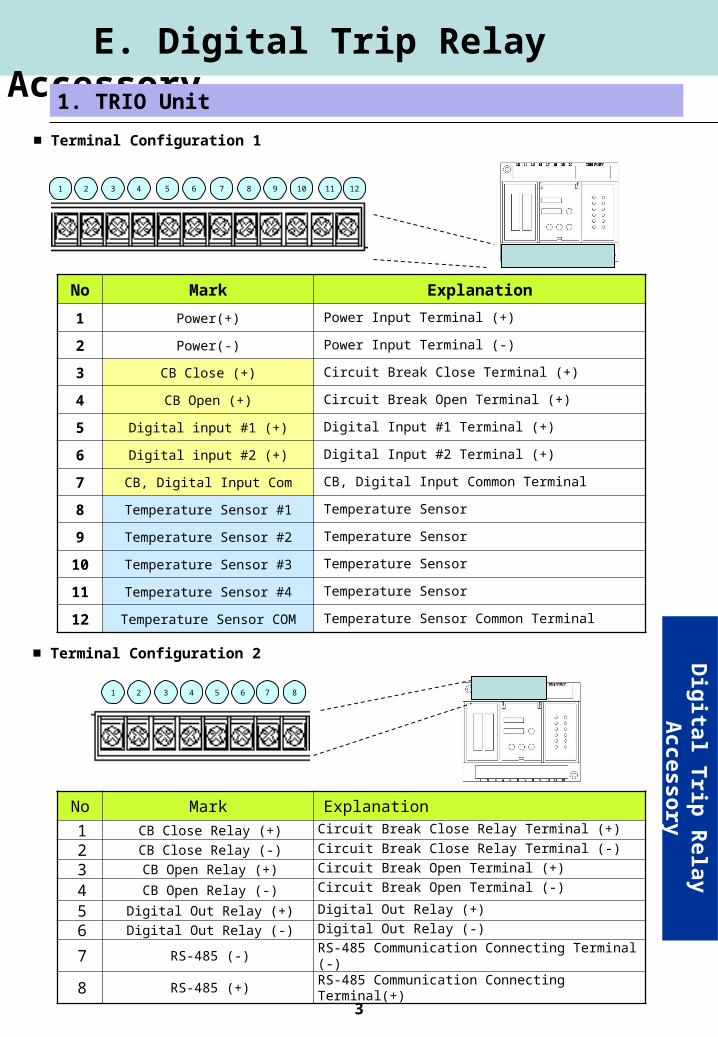
No Mark Explanation
1 Power(+) Power Input Terminal (+)
2 Power(-) Power Input Terminal (-)
3 CB Close (+) Circuit Break Close Terminal (+)
4 CB Open (+) Circuit Break Open Terminal (+)
5 Digital input #1 (+) Digital Input #1 Terminal (+)
6 Digital input #2 (+) Digital Input #2 Terminal (+)
7 CB, Digital Input Com CB, Digital Input Common Terminal
8 Temperature Sensor #1 Temperature Sensor
9 Temperature Sensor #2 Temperature Sensor
10 Temperature Sensor #3 Temperature Sensor
11 Temperature Sensor #4 Temperature Sensor
12 Temperature Sensor COM Temperature Sensor Common Terminal
4 5 6 7 8 9 10 11 12
Terminal Configuration 1
No Mark Explanation
1 CB Close Relay (+) Circuit Break Close Relay Terminal (+)
2 CB Close Relay (-) Circuit Break Close Relay Terminal (-)
3 CB Open Relay (+) Circuit Break Open Terminal (+)
4 CB Open Relay (-) Circuit Break Open Terminal (-)
5 Digital Out Relay (+) Digital Out Relay (+)
6 Digital Out Relay (-) Digital Out Relay (-)
7 RS-485 (-) RS-485 Communication Connecting Terminal (-)
8 RS-485 (+) RS-485 Communication Connecting Terminal(+)
1 2 3 4 5 6 7 8
Terminal Configuration 2
E. Digital Trip Relay Accessory
1. TRIO Unit
Dig
ital Trip
Relay A
ccessory
4
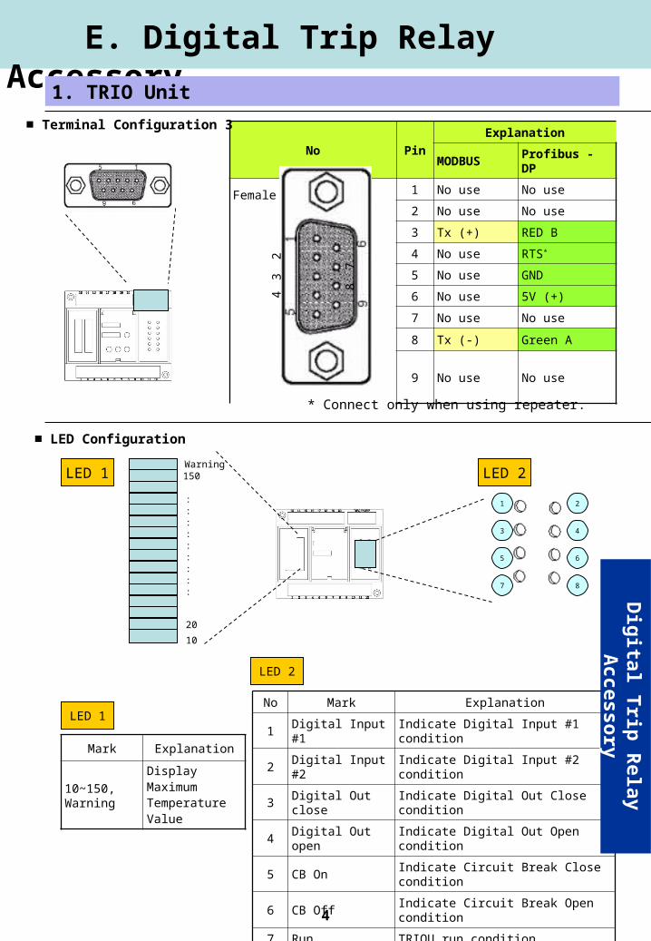
No PinExplanation
MODBUS Profibus - DP
1 No use No use
2 No use No use
3 Tx (+) RED B
4 No use RTS*
5 No use GND
6 No use 5V (+)
7 No use No use
8 Tx (-) Green A
9 No use No use
Female
* Connect only when using repeater.
Terminal Configuration 3
E. Digital Trip Relay Accessory
1 2
3
5
7
4
6
8
LED 1 LED 2
10
150Warning
20
:::::::::
LED Configuration
No Mark Explanation
1 Digital Input #1 Indicate Digital Input #1 condition
2 Digital Input #2 Indicate Digital Input #2 condition
3 Digital Out close Indicate Digital Out Close condition
4 Digital Out open Indicate Digital Out Open condition
5 CB On Indicate Circuit Break Close condition
6 CB Off Indicate Circuit Break Open condition
7 Run TRIOU run condition
8 CB Control ErrIndicate Circuit Break Terminal
Disconnection / Control Err Condition
LED 2
Mark Explanation
10~150, Warning
Display MaximumTemperatureValue
LED 1
23
4
78
1. TRIO Unit
Dig
ital Trip
Relay A
ccessory
5
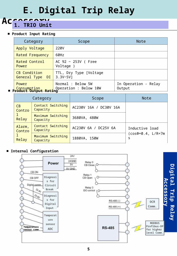
Internal Configuration
Product Input Rating
Category Scope Note
Apply Voltage 220V
Rated Frequency 60Hz
Rated Control Power AC 92 ~ 253V ( Free Voltage )
CB Condition General Type DI
TTL, Dry Type [Voltage 3.3V~5V]
Power ConsumptionNormal : Below 5WOperation : Below 10W
In Operation - Relay Output
Product Output Rating
Category Scope Note
CB ControlRelay
Contact SwitchingCapacity
AC230V 16A / DC30V 16A
Maximum SwitchingCapacity
3680VA, 480W
Alarm, Control Relay
Contact SwitchingCapacity
AC230V 6A / DC25V 6AInductive load
(cosΦ=0.4, L/R=7msMaximum SwitchingCapacity
1880VA, 150W
E. Digital Trip Relay Accessory
1. TRIO Unit
Dig
ital Trip
Relay A
ccessory
Diagnosis
for Circuit
Break
Diagnosis
for Digital
Input
Temperat
ure
sensor
ADC
OCR
Comm.
MODBUSProfibus-DP
for higher level Comm.
Temperature sensor comm.
6
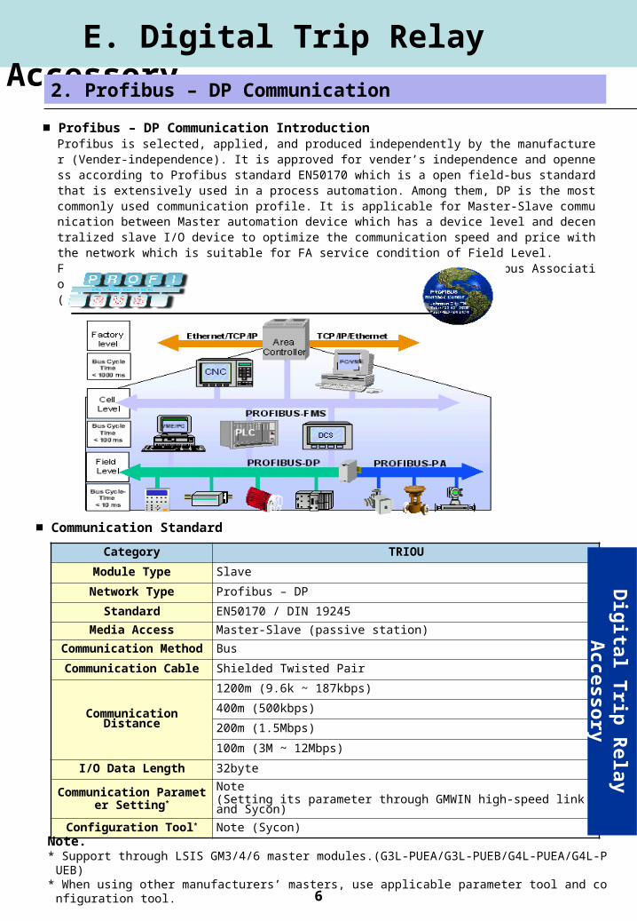
Profibus is selected, applied, and produced independently by the manufacturer (Vender-independence). It is approved for vender’s independence and openness according to Profibus standard EN50170 which is a open field-bus standard that is extensively used in a process automation. Among them, DP is the most commonly used communication profile. It is applicable for Master-Slave communication between Master automation device which has a device level and decentralized slave I/O device to optimize the communication speed and price with the network which is suitable for FA service condition of Field Level. For more details on Profibus-DP, please refer to “Korean Profibus Association” Homepage.( http://www.profibus.co.kr)
Profibus – DP Communication Introduction
E. Digital Trip Relay Accessory
2. Profibus – DP Communication
Category TRIOU
Module Type Slave
Network Type Profibus – DP
Standard EN50170 / DIN 19245
Media Access Master-Slave (passive station)
Communication Method Bus
Communication Cable Shielded Twisted Pair
Communication Distance
1200m (9.6k ~ 187kbps)
400m (500kbps)
200m (1.5Mbps)
100m (3M ~ 12Mbps)
I/O Data Length 32byte
Communication Parameter Setting*
Note (Setting its parameter through GMWIN high-speed link and Sycon)
Configuration Tool* Note (Sycon)
Note.* Support through LSIS GM3/4/6 master modules.(G3L-PUEA/G3L-PUEB/G4L-PUEA/G4L-PUEB)* When using other manufacturers’ masters, use applicable parameter tool and configuration tool.
Communication Standard
Dig
ital Trip
Relay A
ccessory
7
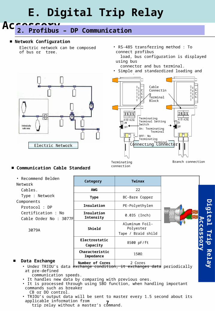
Electric network can be composed of bus or tree.
• RS-485 transferring method : To connect profibus load, bus configuration is displayed using bus connector and bus terminal. • Simple and standardized loading and connecting concept• Easy installation
Connecting ConnectorElectric Network
Network Configuration
E. Digital Trip Relay Accessory
2. Profibus – DP Communication
• Recommend Belden Network
Cables.
Type : Network Components
Protocol : DP
Certification : No
Cable Order No : 3077F
3079A
Category Twinax
AWG 22
Type BC-Bare Copper
Insulation PE-Polyethylen
Insulation Intensity 0.035 (Inch)
ShieldAluminum Foil- Polyester
Tape / Braid shild
Electrostatic
Capacity8500 pF/ft
Characteristic Impedance
150Ω
Number of Cores 2 Cores
Communication Cable Standard
• Under TRIOU’s data exchange condition, it exchanges data periodically at pre-defined communication speeds. • It handles new data by comparing with previous ones. • It is processed through using SBO function, when handling important commands such as breaker CB or DO control. • TRIOU’s output data will be sent to master every 1.5 second about its applicable information from trip relay without a master’s command.
Data Exchange
Cable Connecting Terminal Block
Terminating Terminal Setting Switch
On: Terminating Terminal
OFF: No Terminating Terminal
Terminating connection Branch connection
Dig
ital Trip
Relay A
ccessory
8
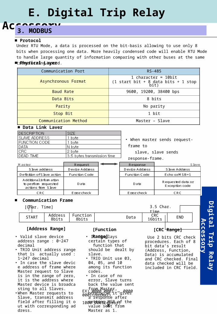
Protocol
Communication Port RS-485
Asynchronous Format 1 character = 10bit(1 start bit + 8 data bits + 1 stop bit)
Baud Rate 9600, 19200, 38400 bps
Data Bits 8 bits
Parity No parity
Stop Bit 1 bit
Communication Method Master – Slave
Under RTU Mode, a data is processed on the bit-basis allowing to use only 8 bits when processing one
data. More heavily condensed code will enable RTU Mode to handle large quantity of information comparing
with other buses at the same transferring speed.
Physical Layer
Data Link Layer
E. Digital Trip Relay Accessory
3. MODBUS
Communication Frame
Address8bits
Function8bits Data CRC
16bits ENDSTART
3.5 Char. time[Char. Time]
[Address Range]
• Valid slave device address range : 0~247 decimal
• TRIO Unit address range that is actually used : 1~247 decimal
• In case the slave device address of frame where Master request to Slave is in the range of zero, it is the address where Master device is broadcasting to all Slaves.
• When Master requests to Slave, transmit address field after filling it out with corresponding address.
[Function Range]
• It displays certain types of
function that should be dealt by slave.
• TRIO Unit use 03, 04, 05, and 10 among its function codes.
• In case of no error, Slave turns back the value sent from Master, otherwise it gives a response after setting MSB of the value sent from Master as 1.
[CRC Range]
Use 2 bits CRC check procedures. Each of 8 bit data’s result (Address, Function, Data) is accumulated and CRC checked. Final data checked will be included in CRC field.
EX) 0000 0001 ⇒ 0000 0001(normal) 1000 0001(error)
Dig
ital Trip
Relay A
ccessory
• When master sends request-frame to
slave, slave sends response-frame.
Master Request Response Slave
Slave address Device Address Device Address Slave Address
Definition of Slave action Function Code Function Code Echo or MSB=1
Additional informationto perform requestedactions from Slave
Data DataRequested data or
Exception code
CRC Error check Error check CRC