π Speakers “Crossover Electronics 101”€œCrossover Electronics 101” Overview 1. Resistors -...
51
π Speakers “Crossover Electronics 101” Overview 1. Resistors - Ohms Law Voltage Dividers and L-Pads 2. Reactive components - Inductors and Capacitors 3. Resonance 4. Peaking 5. Damping
Transcript of π Speakers “Crossover Electronics 101”€œCrossover Electronics 101” Overview 1. Resistors -...

π Speakers
“Crossover Electronics 101”
Overview
1. Resistors - Ohms Law
Voltage Dividers and L-Pads
2. Reactive components - Inductors and Capacitors
3. Resonance
4. Peaking
5. Damping
1
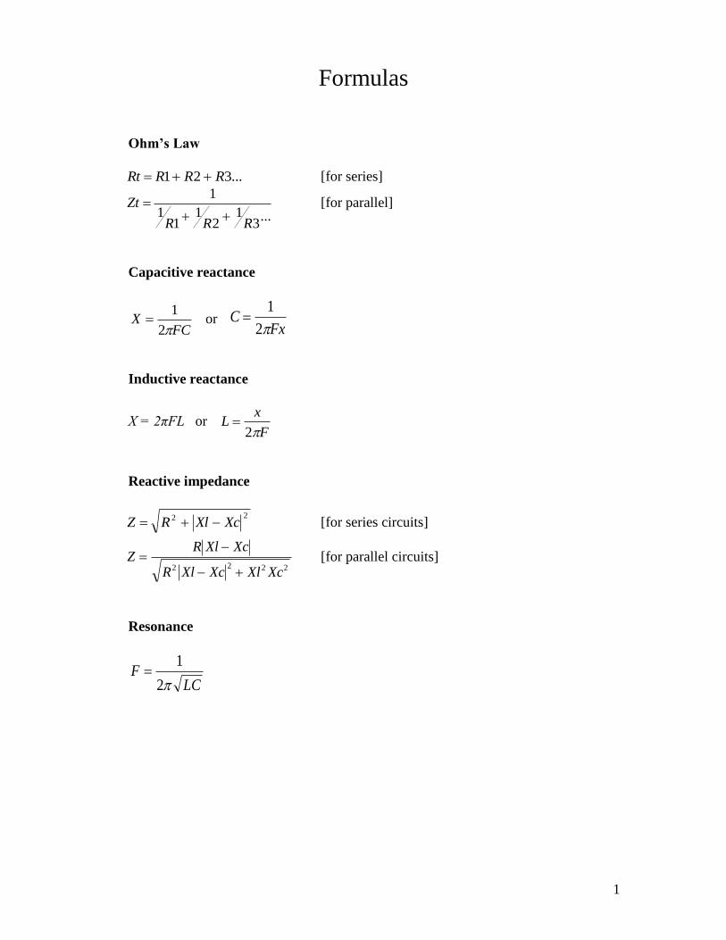
Formulas
Ohm’s Law
...321 RRRRt [for series]
...
31
21
11
1
RRR
Zt
[for parallel]
Capacitive reactance
FC
X2
1 or C
Fx
1
2
Inductive reactance
X = 2πFL or Lx
F
2
Reactive impedance
22 XcXlRZ [for series circuits]
ZR Xl Xc
R Xl Xc Xl Xc
2 2 2 2 [for parallel circuits]
Resonance
LCF
2
1
2
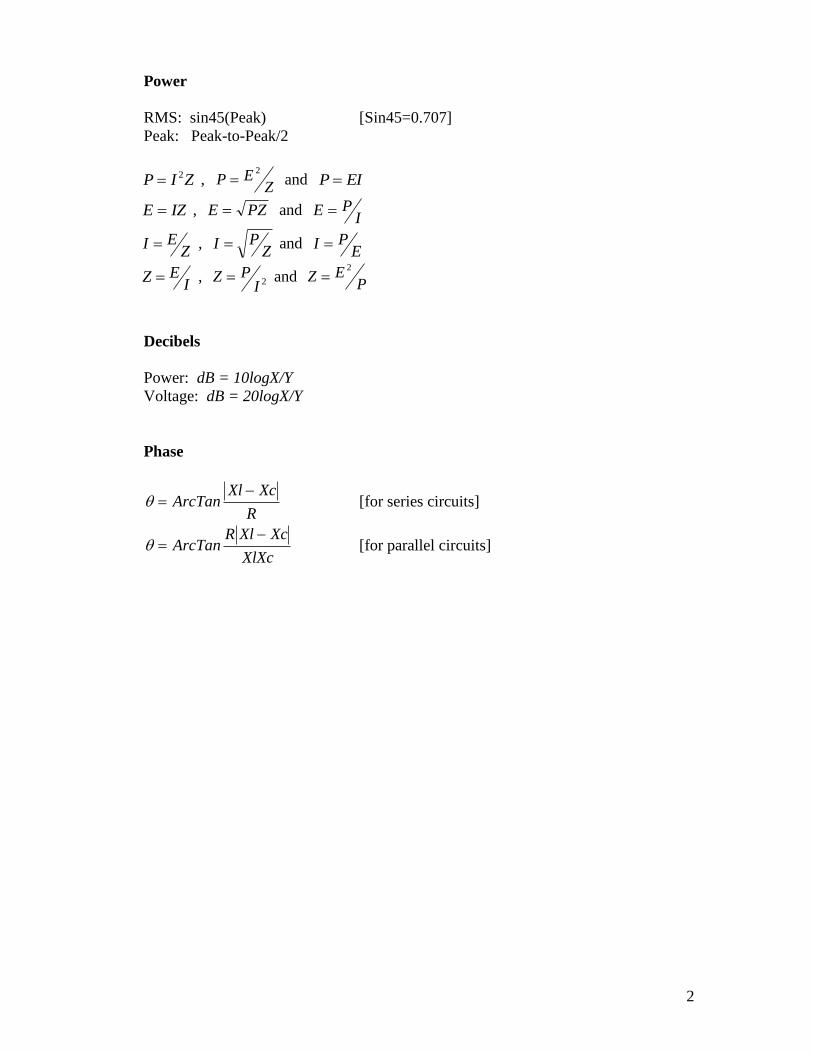
Power
RMS: sin45(Peak) [Sin45=0.707]
Peak: Peak-to-Peak/2
P I Z 2 , P EZ
2
and P EI
E IZ , E PZ and E PI
I EZ
, I PZ
and I PE
Z EI
, Z PI
2 and Z EP
2
Decibels
Power: dB = 10logX/Y
Voltage: dB = 20logX/Y
Phase
ArcTanXl Xc
R [for series circuits]
ArcTanR Xl Xc
XlXc [for parallel circuits]
3
Resistors
Ohm’s Law
Series connection
21 RRRt
Parallel connection
21
11
1
RR
Rt
Examples:
Series R1=8 ohms, R2=8 ohms, Rt=16 ohms
Parallel R1=8 ohms, R2=8 ohms, Rt=4 ohms
For series/parallel, calculate the branches separately.
An example is the L-Pad, which has a series and parallel component connected to the
speaker load. So calculate the parallel branch first, to find the equivalent value. Then
calculate this value connected in series with the other resistance to find the total.
Speaker=8 ohms, Series resistance = 4 ohms, Parallel resistance=6 ohms
Parallel branch = 3.43 ohms, Rt=7.43 ohms
Voltage Dividers
A pair of resistors forms a voltage divider, where voltage (and power) is proportioned
within the system. A fixed ratio is produced, so the value at the load is a percentage of
the input. This can be expressed in decibels.
The simplest voltage divider is one where two resistors of the same value are connected
in series. This always results in an even division of voltage and power between the two.
Such an arrangement always results in 6dB reduction.
4
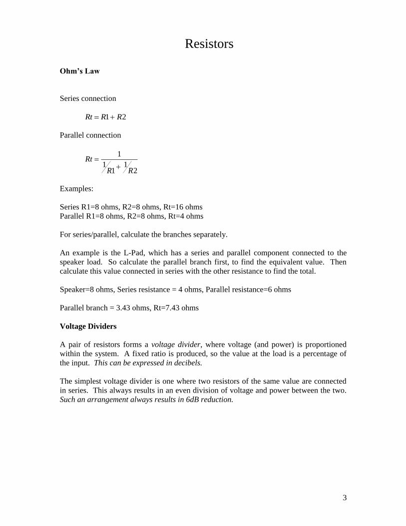
An example is a simple network having two 8 ohm resistors. If a speaker motor were a
perfectly resistive 8 ohm load, then R2 would represent the loudspeaker load. R1 could
be a series resistor used as an attenuator, or it could also be another loudspeaker motor.
At any rate, this simplified model of a purely resistive loudspeaker motor is how speaker
circuits are often visualized.
This connection ensures that the same current will pass through each series component.
Find current through the network, using a reference voltage:
I = E/R
Using 10 volts as our reference, we see that current would be equal to 10/16 or 0.625
amperes. This can also be written as 0.625A or 625mA.
We can find the voltage across each component by rearranging the formula:
E = IR
Since 625mA passes through the series circuit, we find that the voltage across each
resistor is 0.625 x 8, or 5 volts. This makes sense, that the 10 volts across the network
would be split 50/50 across equal value resistors.
Now to find the ratio expressed in decibels:
dB = 20logX/Y; 6 = 20 log (5/10)
So we can always expect 6dB reduction from a series resistance equal to the load.
5
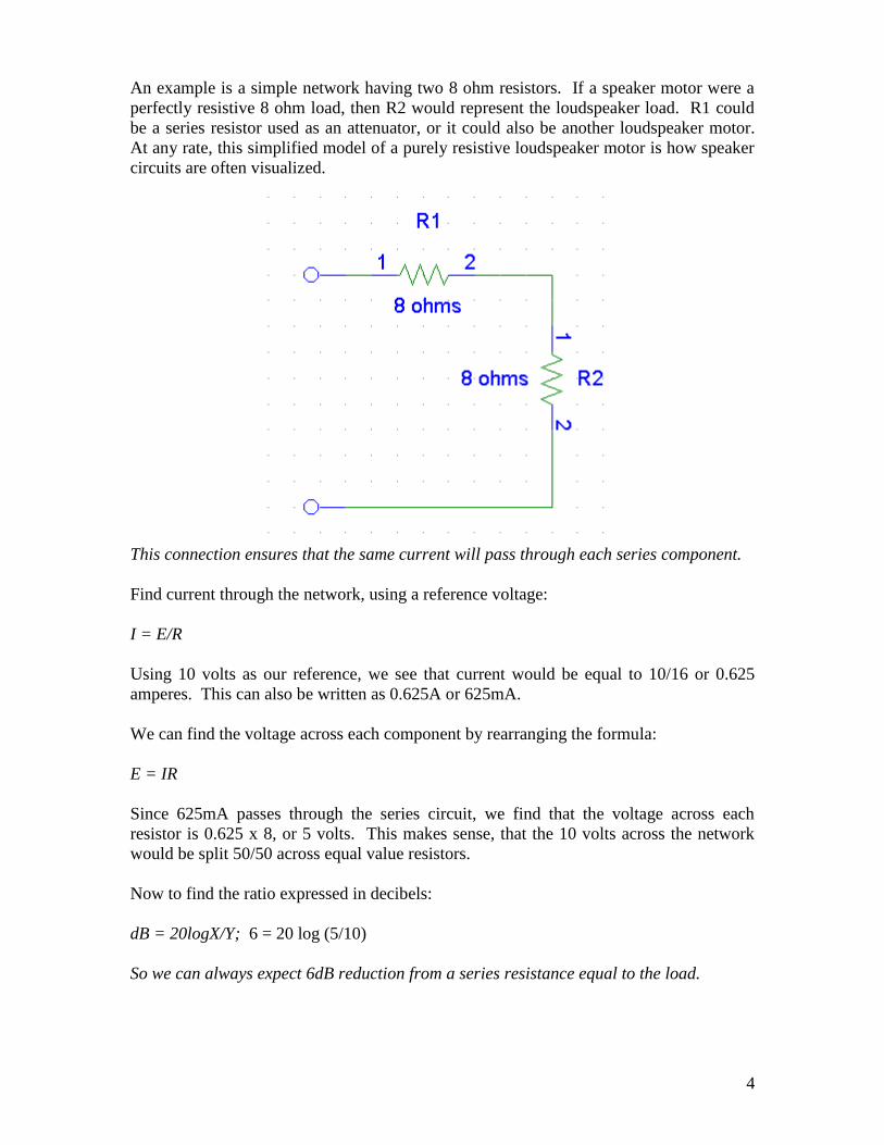
Another example is a network having a 25 ohm resistor and an 8 ohm resistor connected
in series. This would be a common configuration for a circuit where R1 were a series
attenuator and R2 were a loudspeaker motor.
Total resistance is 25 + 8 = 33 ohms. So find current through the network, using a
reference voltage:
I = E/R
Using 10 volts as our reference, we see that current would be equal to 10/33 or 0.303A,
which is also written as 303mA.
We can find the voltage across each component by rearranging the formula:
E = IR
Since 303mA passes through the series circuit, we find that the voltage across R1 is 0.303
x 25 = 7.58v and R2 is 0.303 x 8 = 2.42v. Notice that the two voltages add up to equal
the source, which is exactly what we might expect. This is true of two purely resistive
components connected in series.
Now to find the amount of attenuation to R2 expressed in decibels:
dB = 20logX/Y; 12.3 = 20 log (2.42/10)
So this circuit provides 12dB attenuation. Interestingly, to double the amount of
attenuation required much more than double the amount of series resistance.
6
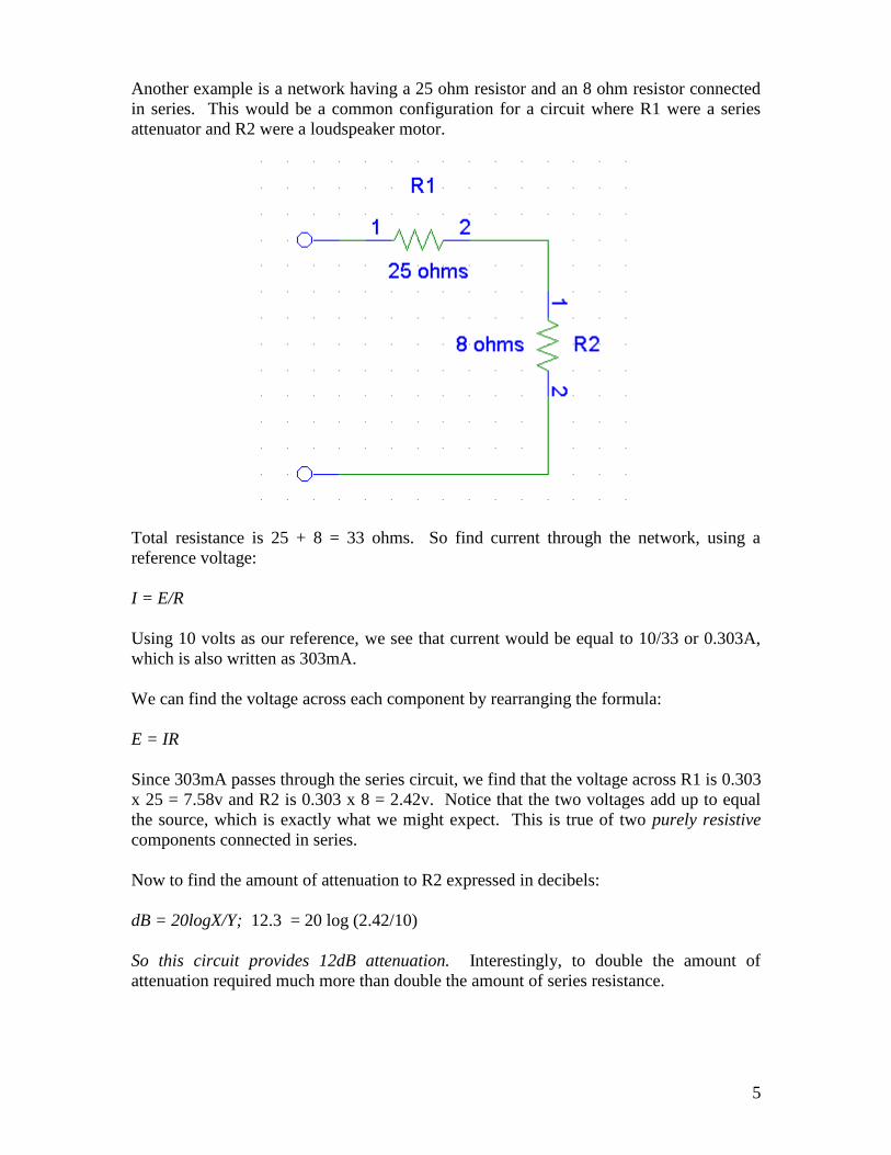
Here’s a simple parallel network having two 8 ohm resistors. In this case, the most likely
reason for the connection would be to use two loudspeakers together on a common line.
Another reason to make this sort of connection is to add an 8 ohm resistor across a
speaker for impedance matching reasons or to change system damping, which will be
discussed later in this document.
This connection ensures that the same voltage will be across both parallel components.
Find current through each component, using a reference voltage:
I = E/R
Using 10 volts as our reference, we see that current would be equal to 10/8 or 1.25A
through each individual 8 ohm resistor. Also, we see that since the total resistance of the
network is equal to 4 ohms, the total current through the network is 2.5A with a 10 volt
source.
7
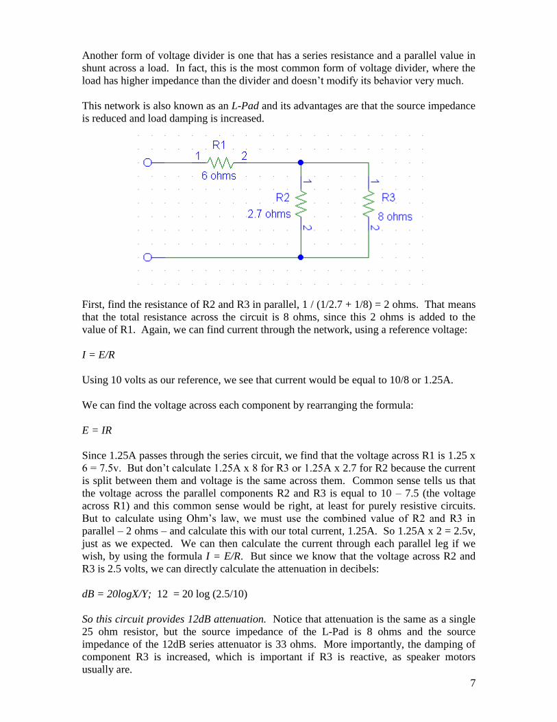
Another form of voltage divider is one that has a series resistance and a parallel value in
shunt across a load. In fact, this is the most common form of voltage divider, where the
load has higher impedance than the divider and doesn’t modify its behavior very much.
This network is also known as an L-Pad and its advantages are that the source impedance
is reduced and load damping is increased.
First, find the resistance of R2 and R3 in parallel, 1 / (1/2.7 + 1/8) = 2 ohms. That means
that the total resistance across the circuit is 8 ohms, since this 2 ohms is added to the
value of R1. Again, we can find current through the network, using a reference voltage:
I = E/R
Using 10 volts as our reference, we see that current would be equal to 10/8 or 1.25A.
We can find the voltage across each component by rearranging the formula:
E = IR
Since 1.25A passes through the series circuit, we find that the voltage across R1 is 1.25 x
6 = 7.5v. But don’t calculate 1.25A x 8 for R3 or 1.25A x 2.7 for R2 because the current
is split between them and voltage is the same across them. Common sense tells us that
the voltage across the parallel components R2 and R3 is equal to 10 – 7.5 (the voltage
across R1) and this common sense would be right, at least for purely resistive circuits.
But to calculate using Ohm’s law, we must use the combined value of R2 and R3 in
parallel – 2 ohms – and calculate this with our total current, 1.25A. So 1.25A x 2 = 2.5v,
just as we expected. We can then calculate the current through each parallel leg if we
wish, by using the formula I = E/R. But since we know that the voltage across R2 and
R3 is 2.5 volts, we can directly calculate the attenuation in decibels:
dB = 20logX/Y; 12 = 20 log (2.5/10)
So this circuit provides 12dB attenuation. Notice that attenuation is the same as a single
25 ohm resistor, but the source impedance of the L-Pad is 8 ohms and the source
impedance of the 12dB series attenuator is 33 ohms. More importantly, the damping of
component R3 is increased, which is important if R3 is reactive, as speaker motors
usually are.
8
Reactive components
Reactive impedance
Inductors
X = 2πFL, Rearranged to find for Inductance, F
XL
2
Capacitors
FCX
2
1 , Rearranged to find for Capacitance,
FXC
2
1
X is reactive impedance, measured in ohms. Reactive impedance is like resistance – It is
an impedance to current and can be calculated with Ohm’s law, same as resistors. But
only with other components of the same type. In other words, if only inductors are in a
circuit, then Ohm’s law applies. If only capacitors are in a circuit, then Ohm’s law
applies again. But if reactive components are mixed, or if resistance is included, then
other calculations must be used.
This is because capacitance has voltage leading current, and is 90 degrees out of phase
with resistance. Inductance has current leading resistance and is 90 degrees out of phase
the other way. So inductance and capacitance are 180 degrees away from each other, and
as you might expect, this brings some unusual and interesting properties. One of them is
resonance, which is discussed later.
Another interesting property is the relationship of frequency to impedance with reactive
components. That is one of their most important features. A reactive component –
inductor or capacitor – has specific impedance at only one frequency. As frequency rises,
inductive impedance increases but capacitive impedance decreases. Said another way, an
inductor’s impedance rises as frequency goes up and a capacitor’s impedance falls as
frequency goes up. So if a capacitor is 16 ohms at 2kHz, it will be 8 ohms at 4kHz, and
so on.
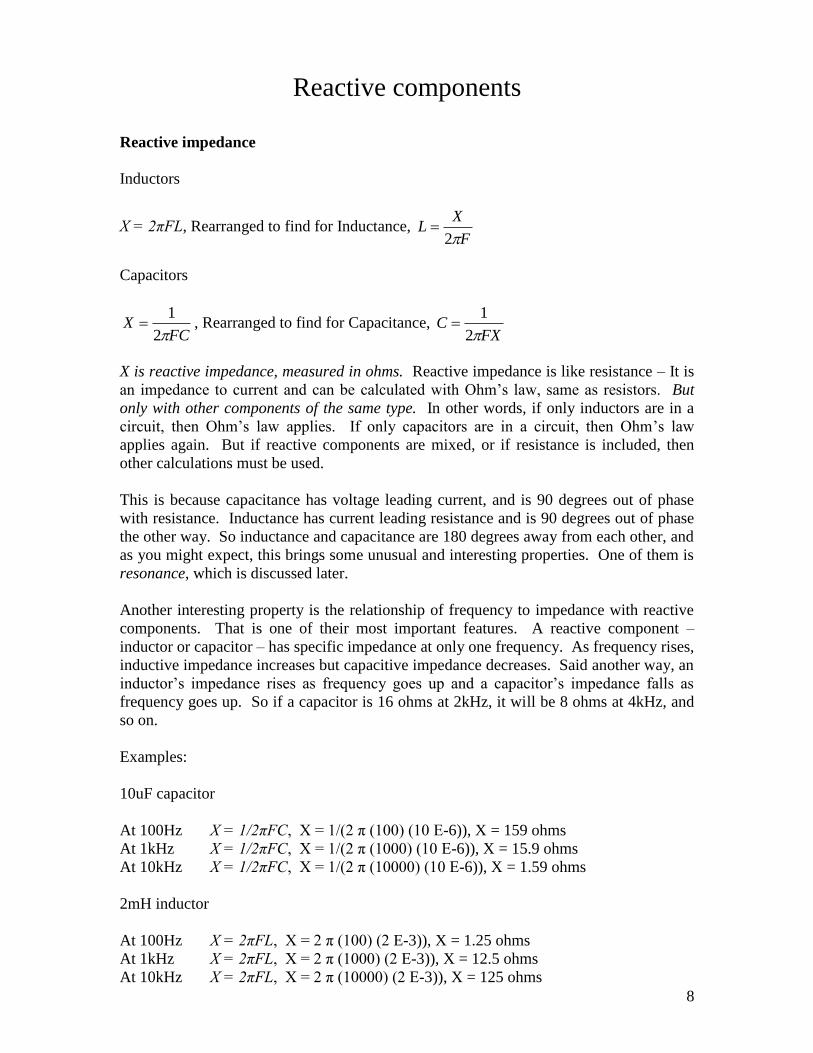
Examples:
10uF capacitor
At 100Hz X = 1/2πFC, X = 1/(2 π (100) (10 E-6)), X = 159 ohms
At 1kHz X = 1/2πFC, X = 1/(2 π (1000) (10 E-6)), X = 15.9 ohms
At 10kHz X = 1/2πFC, X = 1/(2 π (10000) (10 E-6)), X = 1.59 ohms
2mH inductor
At 100Hz X = 2πFL, X = 2 π (100) (2 E-3)), X = 1.25 ohms
At 1kHz X = 2πFL, X = 2 π (1000) (2 E-3)), X = 12.5 ohms
At 10kHz X = 2πFL, X = 2 π (10000) (2 E-3)), X = 125 ohms
9
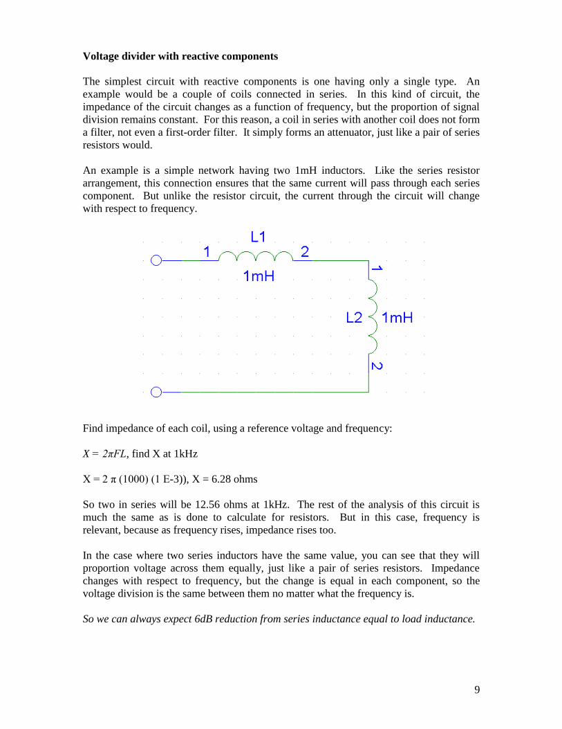
Voltage divider with reactive components
The simplest circuit with reactive components is one having only a single type. An
example would be a couple of coils connected in series. In this kind of circuit, the
impedance of the circuit changes as a function of frequency, but the proportion of signal
division remains constant. For this reason, a coil in series with another coil does not form
a filter, not even a first-order filter. It simply forms an attenuator, just like a pair of series
resistors would.
An example is a simple network having two 1mH inductors. Like the series resistor
arrangement, this connection ensures that the same current will pass through each series
component. But unlike the resistor circuit, the current through the circuit will change
with respect to frequency.
Find impedance of each coil, using a reference voltage and frequency:
X = 2πFL, find X at 1kHz
X = 2 π (1000) (1 E-3)), X = 6.28 ohms
So two in series will be 12.56 ohms at 1kHz. The rest of the analysis of this circuit is
much the same as is done to calculate for resistors. But in this case, frequency is
relevant, because as frequency rises, impedance rises too.
In the case where two series inductors have the same value, you can see that they will
proportion voltage across them equally, just like a pair of series resistors. Impedance
changes with respect to frequency, but the change is equal in each component, so the
voltage division is the same between them no matter what the frequency is.
So we can always expect 6dB reduction from series inductance equal to load inductance.
10
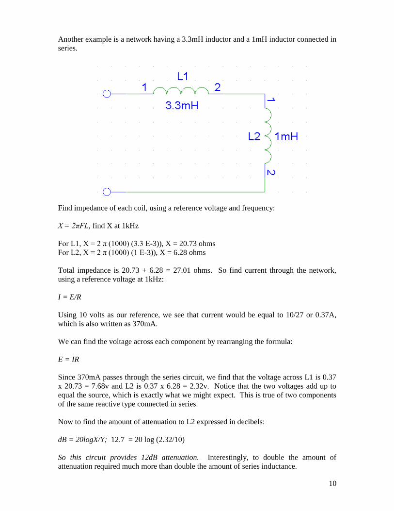
Another example is a network having a 3.3mH inductor and a 1mH inductor connected in
series.
Find impedance of each coil, using a reference voltage and frequency:
X = 2πFL, find X at 1kHz
For L1, X = 2 π (1000) (3.3 E-3)), X = 20.73 ohms
For L2, X = 2 π (1000) (1 E-3)), X = 6.28 ohms
Total impedance is 20.73 + 6.28 = 27.01 ohms. So find current through the network,
using a reference voltage at 1kHz:
I = E/R
Using 10 volts as our reference, we see that current would be equal to 10/27 or 0.37A,
which is also written as 370mA.
We can find the voltage across each component by rearranging the formula:
E = IR
Since 370mA passes through the series circuit, we find that the voltage across L1 is 0.37
x 20.73 = 7.68v and L2 is 0.37 x 6.28 = 2.32v. Notice that the two voltages add up to
equal the source, which is exactly what we might expect. This is true of two components
of the same reactive type connected in series.
Now to find the amount of attenuation to L2 expressed in decibels:
dB = 20logX/Y; 12.7 = 20 log (2.32/10)
So this circuit provides 12dB attenuation. Interestingly, to double the amount of
attenuation required much more than double the amount of series inductance.
11
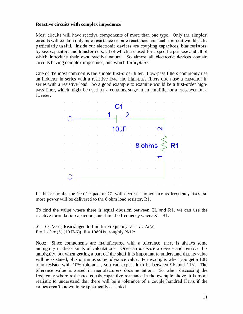
Reactive circuits with complex impedance
Most circuits will have reactive components of more than one type. Only the simplest
circuits will contain only pure resistance or pure reactance, and such a circuit wouldn’t be
particularly useful. Inside our electronic devices are coupling capacitors, bias resistors,
bypass capacitors and transformers, all of which are used for a specific purpose and all of
which introduce their own reactive nature. So almost all electronic devices contain
circuits having complex impedance, and which form filters.
One of the most common is the simple first-order filter. Low-pass filters commonly use
an inductor in series with a resistive load and high-pass filters often use a capacitor in
series with a resistive load. So a good example to examine would be a first-order high-
pass filter, which might be used for a coupling stage in an amplifier or a crossover for a
tweeter.
In this example, the 10uF capacitor C1 will decrease impedance as frequency rises, so
more power will be delivered to the 8 ohm load resistor, R1.
To find the value where there is equal division between C1 and R1, we can use the
reactive formula for capacitors, and find the frequency where X = R1.
X = 1 / 2πFC, Rearranged to find for Frequency, F = 1 / 2πXC
F = 1 / 2 π (8) (10 E-6)), F = 1989Hz, roughly 2kHz.
Note: Since components are manufactured with a tolerance, there is always some
ambiguity in these kinds of calculations. One can measure a device and remove this
ambiguity, but when getting a part off the shelf it is important to understand that its value
will be as stated, plus or minus some tolerance value. For example, when you get a 10K
ohm resistor with 10% tolerance, you can expect it to be between 9K and 11K. The
tolerance value is stated in manufacturers documentation. So when discussing the
frequency where resistance equals capacitive reactance in the example above, it is more
realistic to understand that there will be a tolerance of a couple hundred Hertz if the
values aren’t known to be specifically as stated.
12
At approximately 2kHz, the impedance of the 10uF capacitor C1 will be 8 ohms, which is
equal to the load resistor R1. One might expect voltage across each component to be ½
the source value, as it was with resistors. But in the case of circuits with complex
reactance, something unusual happens.
The reason is that series impedance is calculated with Pythagorean’s formula, and the
total impedance is less than the sum of the two components. So calculate the total
impedance of the circuit:
Z R Xl Xc 2 2
Since there is no inductance in this circuit, “Xl” = 0, and the formula becomes:
22 XcRZ , 22 88 Z , 128Z , Z = 11.31 ohms
This is interesting. Notice that we now have two series impedances, each of 8 ohms, but
the total impedance is not 16 ohms.
So find current through the network, using a reference voltage at 2kHz:
I = E/Z
Using 10 volts as our reference, we see that current would be equal to 10/11.31 or
0.884A, which is also written as 884mA.
Since 884mA passes through the series circuit, we find that the voltage across C1 is 0.884
x 8 = 7.07v and R2 is 0.884 x 8 = 7.07v. Notice that the two voltages do not add up to
equal the source, which is the result of having two components of the different reactive
type connected in series.
A couple points of interest, or maybe “trivial trivia.” Get out your calculators.
Notice that the voltage across each component was 7.07v. It was 0.707 x the total
voltage across the network. This is because the two reactive impedances were equal,
resulting in 45 degrees of phase shift. Now, using your calculator, find the SIN of 45
degrees. It’s 0.707. This is a sort of “magic number” in electronics, sort of like π. You’ll see this value over and over again.
Now to find the amount of attenuation to R1 expressed in decibels:
dB = 20logX/Y; 3 = 20 log (7.07/10)
So this circuit provides 3dB attenuation at the frequency where capacitive reactance
equals resistance. It also provides 6dB/octave attenuation below that, as is shown in the
response chart below. You can calculate a series of points just like we’ve done above to
plot this curve:
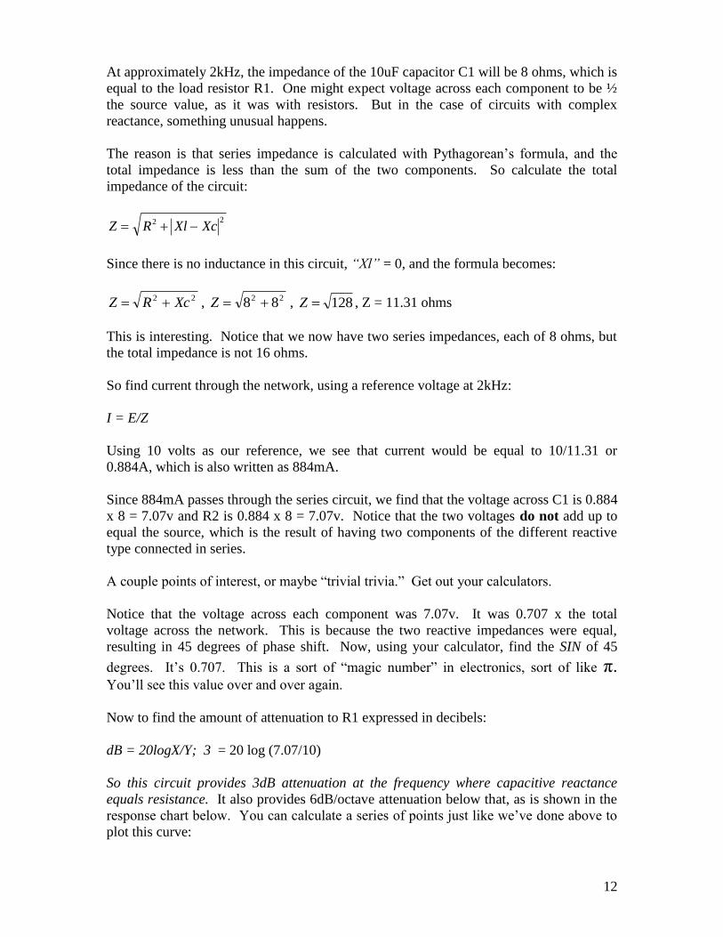
13
First-order response curve
The response curve above represents the power developed across the load – resistor R1 in
the circuit above – in a first-order high-pass network. The filter shown above has
capacitive reactance equal to resistance at 2kHz, so if it were used as a crossover, it
would be said to have a crossover frequency of 2kHz. The crossover frequency has 3dB
attenuation, and there is 6dB attenuation per octave below that.
Low-pass first order networks are very similar, except the reactive component is an
inductor. The curve has the same asymptotic slope but it falls from left to right, passing
more energy at low frequencies.
14
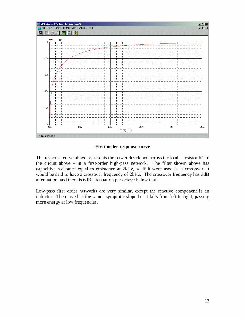
Resonance
You may have noticed a peculiar property of reactive circuits is that the sum of all the
voltages within the circuit seem to be greater than the source. But wait until you see what
happens to a circuit in resonance.
The first thing of interest is the resonant frequency, which is found by the formula:
LCF
2
1
This tells us the precise frequency where inductive reactance and capacitive reactance are
equal.
)610)(36.0(2
1
EEF
,
962
1
EF
,
487.4
1
EF , F= 2054Hz
So this circuit is in resonance at 2kHz.
From our last example, we saw that the 10uF capacitor C1 was 8 ohms at 2kHz, so it
must be very close to this value at 2.054kHz. And the value of the 0.6mH coil L1 must
also be very nearly 8 ohms, since resonance requires that inductive reactance be equal to
capacitive reactance. But it can’t hurt to run the numbers and see.
15
XL = 2πFL and XC = FC2
1
The resonant frequency is 2054, so these XL and XC at this frequency:
XL = 2πFL, XL = 2π(2054)(0.6E-3), XL = 2π(1.23), XL = 7.74 ohms.
XC = FC2
1, XC =
)610)(2054(2
1
E, XC =
)2054.2(2
1
E, XC = 7.74 ohms.
Now here’s where it gets interesting. Let’s use a reference voltage and find the current
through the circuit. First, we must calculate the total impedance of the circuit:
Z R Xl Xc 2 2
Since there is no resistor in this circuit, “R” = 0, and the formula becomes:
2XcXlZ ,
274.774.7 Z , Z = 0
This is really interesting. What this means is that at the resonant frequency, impedance
approaches zero so current approaches infinity. No matter what voltage we plug into the
formula, I = E/Z, current will be infinite if impedance is zero.
Notice that I used the phrases “approaches zero” and “approaches infinity.” This is
because, in practice, there is always some internal resistance in the circuit, and nothing is
purely reactive. Even if the circuit is made using superconductors that have ultra-low
internal resistance, there still is some. There is resistance in the coil. There is resistance
in the source supply, an output transistor or whatever. There is resistance in the
connection wires and there is resistance across the dielectric of the capacitor and in its
leads. So we’ll not be quite able to get infinite current and power from AA batteries,
although the circuit in resonance will certainly cause a shorted condition at this
frequency.
This does cause some interesting conditions though. Since the circuit is nearly a short at
this frequency, current is only limited by the internal resistance of the circuit. So
assuming that the circuit is capable of flowing 10 amperes, the voltage across each
component would rise to 7.74 x 10, or 77.4 volts. This would be true no matter what the
source voltage was.
16
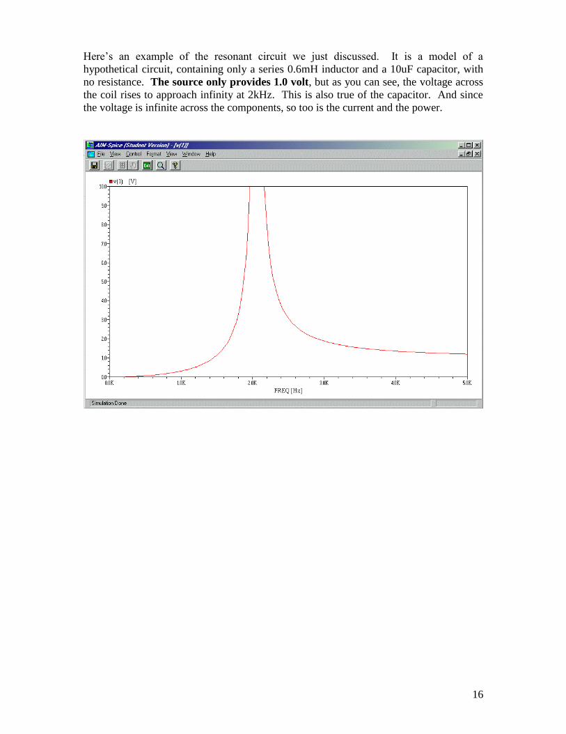
Here’s an example of the resonant circuit we just discussed. It is a model of a
hypothetical circuit, containing only a series 0.6mH inductor and a 10uF capacitor, with
no resistance. The source only provides 1.0 volt, but as you can see, the voltage across
the coil rises to approach infinity at 2kHz. This is also true of the capacitor. And since
the voltage is infinite across the components, so too is the current and the power.
17
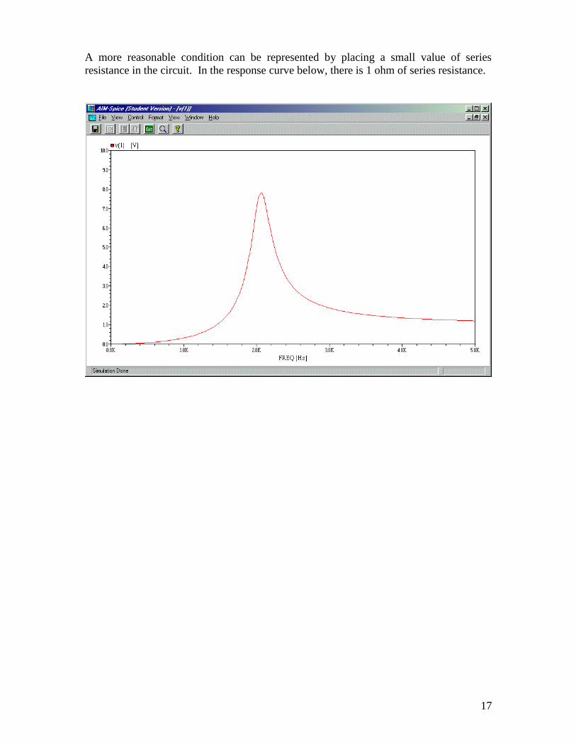
A more reasonable condition can be represented by placing a small value of series
resistance in the circuit. In the response curve below, there is 1 ohm of series resistance.
18
Notice that even with an ohm of series resistance, we still find that eight times as much
voltage is across each reactive component in resonance than was applied to the circuit.
This circuit has 1 volt applied to it but at resonance there’s 8 volts across each
component.
This is why it is important to consider the effects of LC peaking. This condition causes
increased energy across reactive components when in resonance. This means that
speakers are delivered more power when something in the circuit causes this condition.
It can make a peak in the response curve and it can damage speaker motors and crossover
components if high volumes are applied and the condition is severe.
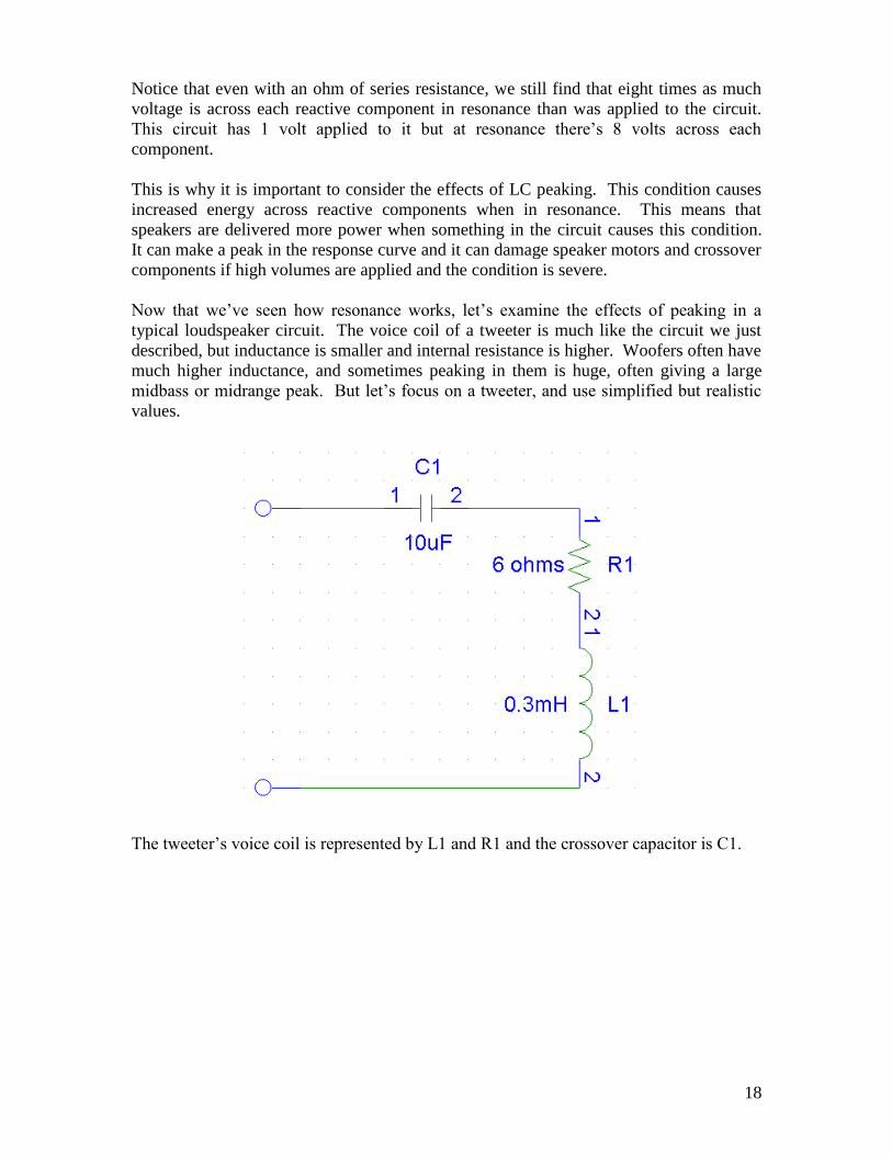
Now that we’ve seen how resonance works, let’s examine the effects of peaking in a
typical loudspeaker circuit. The voice coil of a tweeter is much like the circuit we just
described, but inductance is smaller and internal resistance is higher. Woofers often have
much higher inductance, and sometimes peaking in them is huge, often giving a large
midbass or midrange peak. But let’s focus on a tweeter, and use simplified but realistic
values.
The tweeter’s voice coil is represented by L1 and R1 and the crossover capacitor is C1.
19
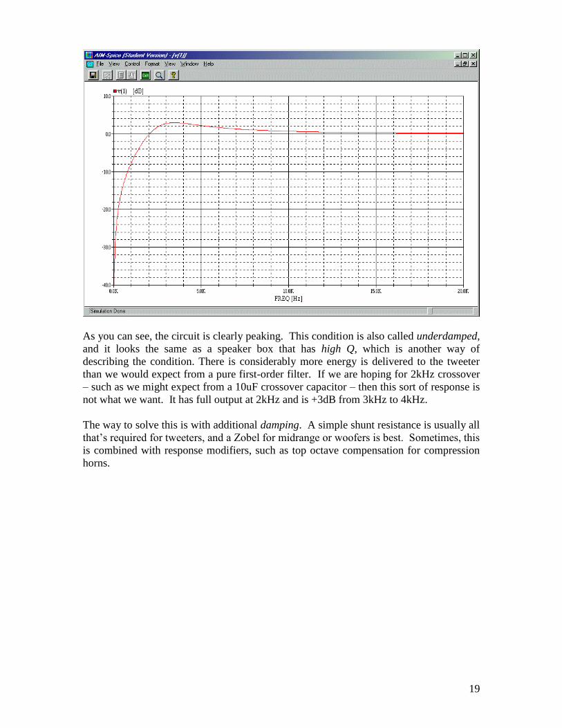
As you can see, the circuit is clearly peaking. This condition is also called underdamped,
and it looks the same as a speaker box that has high Q, which is another way of
describing the condition. There is considerably more energy is delivered to the tweeter
than we would expect from a pure first-order filter. If we are hoping for 2kHz crossover
– such as we might expect from a 10uF crossover capacitor – then this sort of response is
not what we want. It has full output at 2kHz and is +3dB from 3kHz to 4kHz.
The way to solve this is with additional damping. A simple shunt resistance is usually all
that’s required for tweeters, and a Zobel for midrange or woofers is best. Sometimes, this
is combined with response modifiers, such as top octave compensation for compression
horns.
20
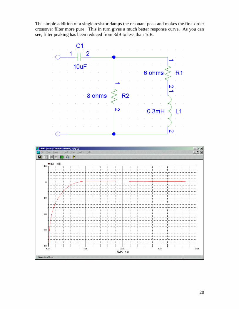
The simple addition of a single resistor damps the resonant peak and makes the first-order
crossover filter more pure. This in turn gives a much better response curve. As you can
see, filter peaking has been reduced from 3dB to less than 1dB.
21
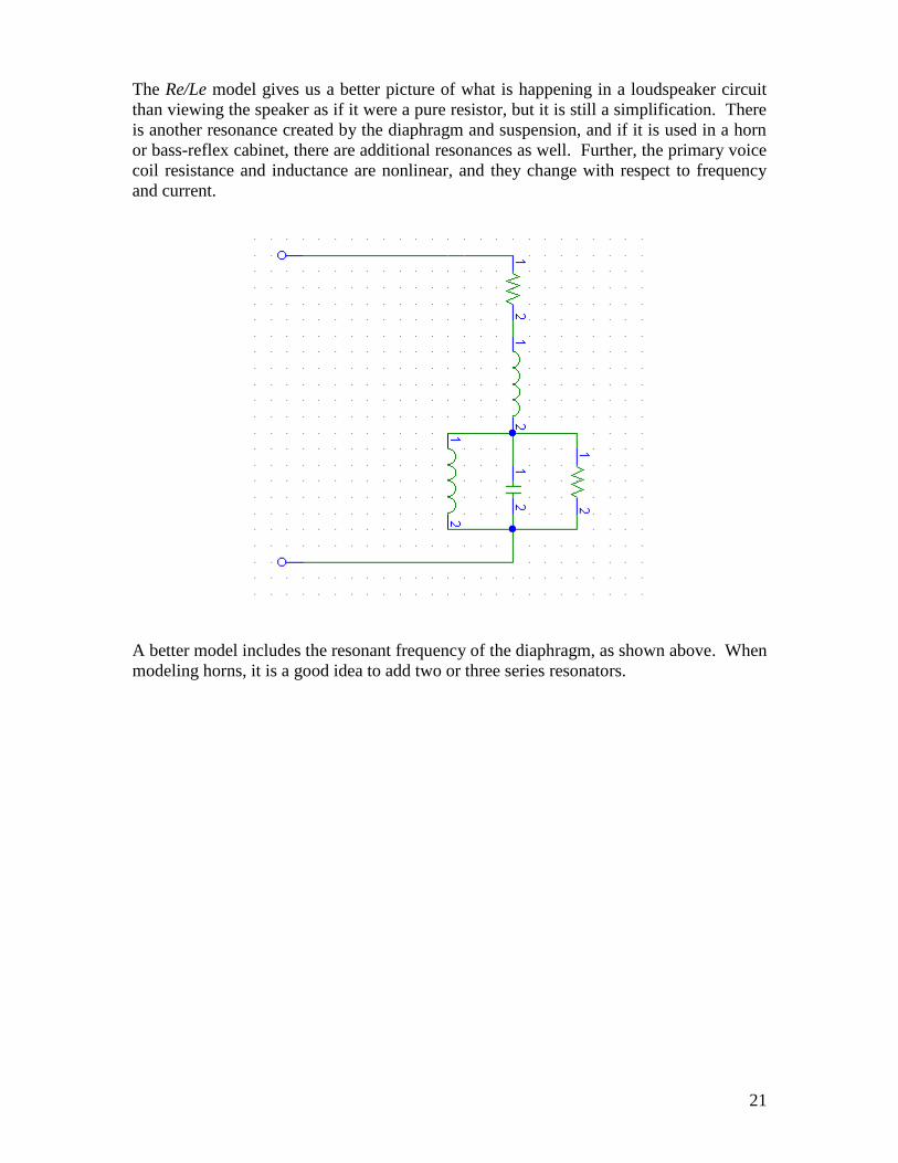
The Re/Le model gives us a better picture of what is happening in a loudspeaker circuit
than viewing the speaker as if it were a pure resistor, but it is still a simplification. There
is another resonance created by the diaphragm and suspension, and if it is used in a horn
or bass-reflex cabinet, there are additional resonances as well. Further, the primary voice
coil resistance and inductance are nonlinear, and they change with respect to frequency
and current.
A better model includes the resonant frequency of the diaphragm, as shown above. When
modeling horns, it is a good idea to add two or three series resonators.
22
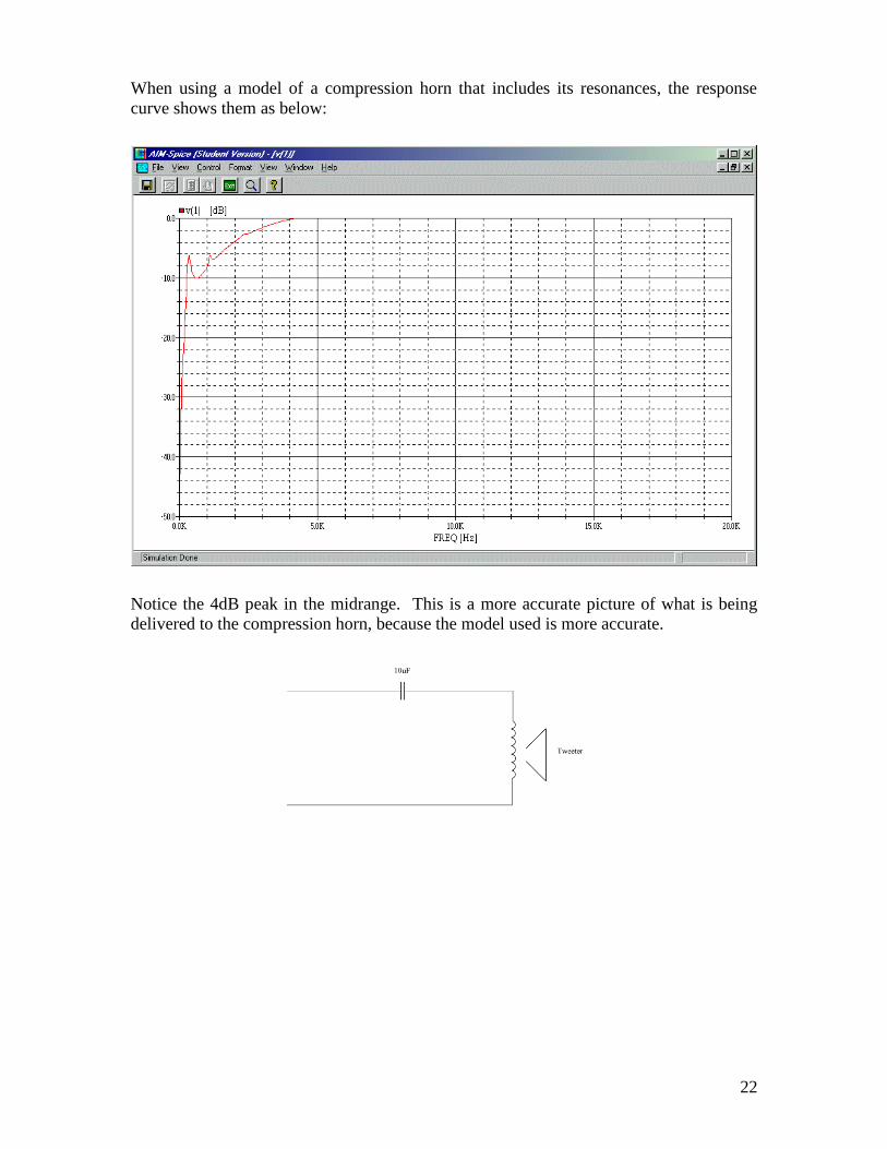
When using a model of a compression horn that includes its resonances, the response
curve shows them as below:
Notice the 4dB peak in the midrange. This is a more accurate picture of what is being
delivered to the compression horn, because the model used is more accurate.

23
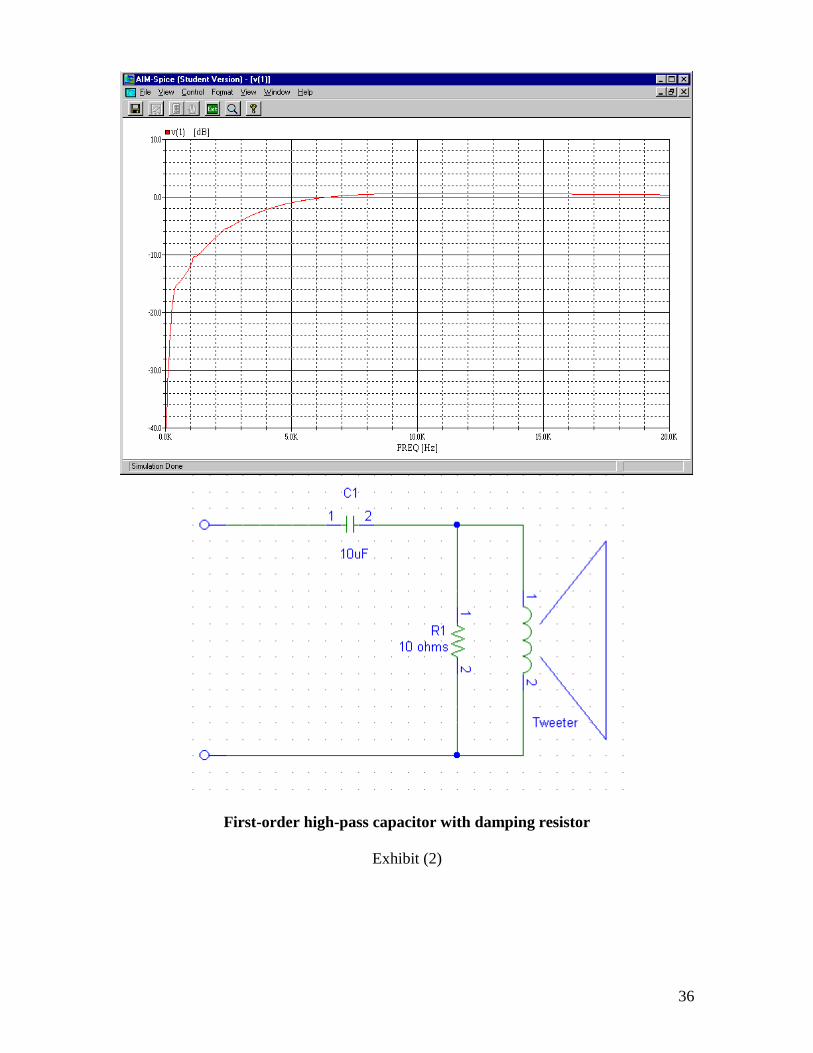
And now, here is the response with a 20 ohm damper resistor installed across the tweeter:
Or with an 8 ohm damper resistor:
As you can see, installing a damping resistor of 10-20 ohms provides better response than
a single-capacitor crossover without the damper. This is almost always true.
24
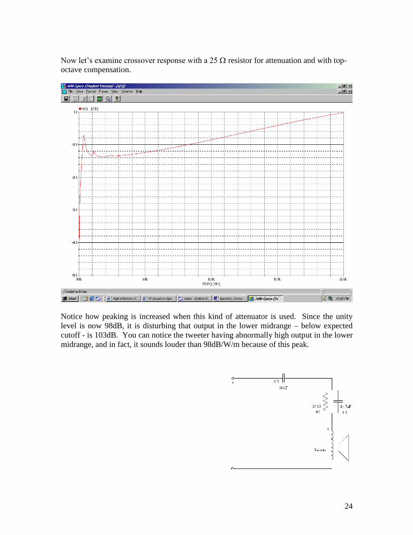
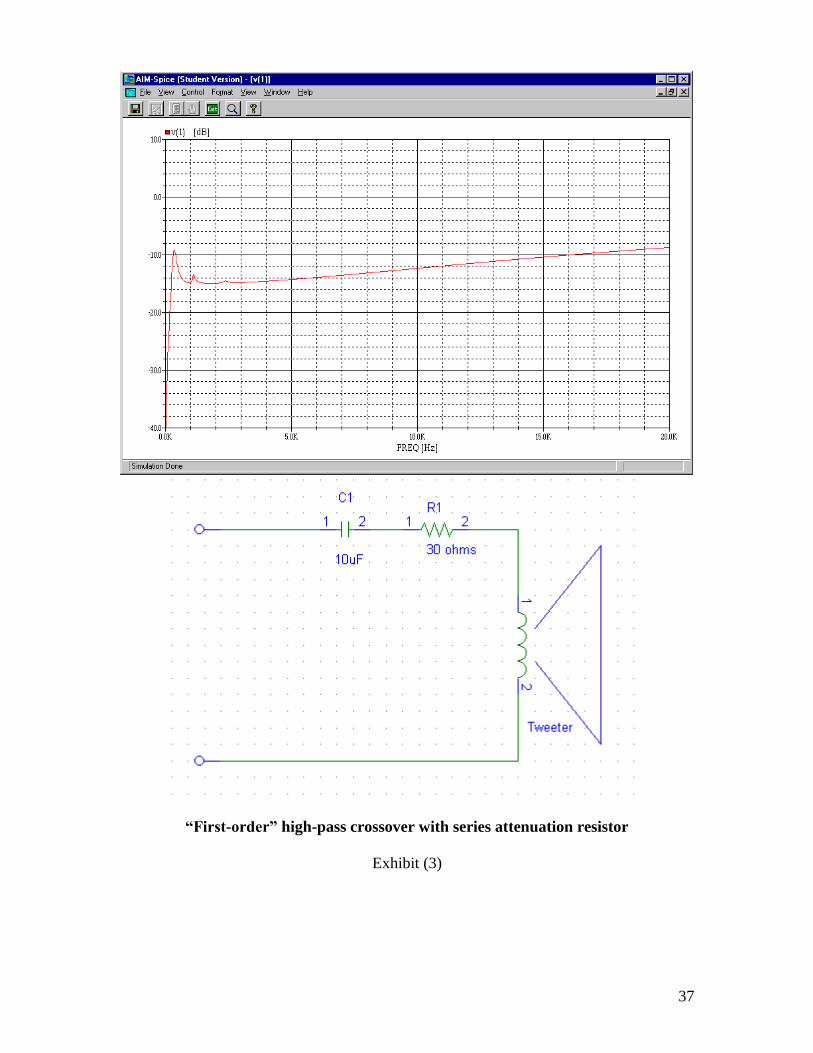
Now let’s examine crossover response with a 25 resistor for attenuation and with top-
octave compensation.
Notice how peaking is increased when this kind of attenuator is used. Since the unity
level is now 98dB, it is disturbing that output in the lower midrange – below expected
cutoff - is 103dB. You can notice the tweeter having abnormally high output in the lower
midrange, and in fact, it sounds louder than 98dB/W/m because of this peak.
25
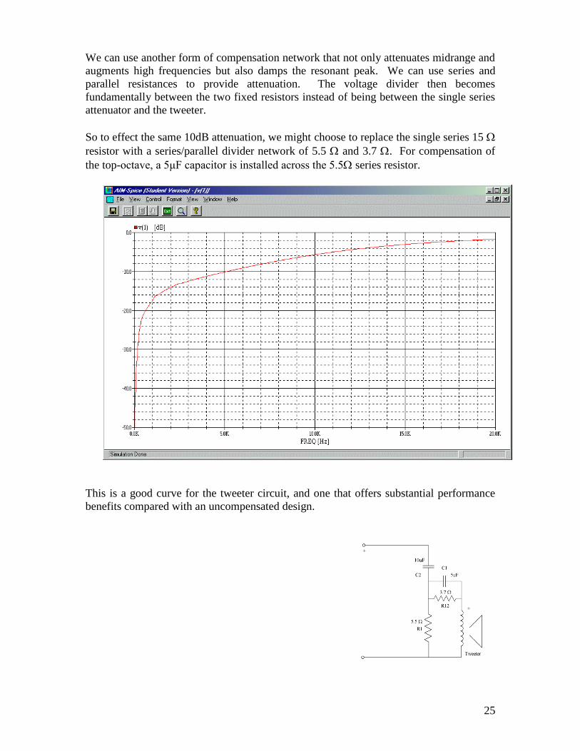
We can use another form of compensation network that not only attenuates midrange and
augments high frequencies but also damps the resonant peak. We can use series and
parallel resistances to provide attenuation. The voltage divider then becomes
fundamentally between the two fixed resistors instead of being between the single series
attenuator and the tweeter.
So to effect the same 10dB attenuation, we might choose to replace the single series 15
resistor with a series/parallel divider network of 5.5 and 3.7 . For compensation of
the top-octave, a 5μF capacitor is installed across the 5.5 series resistor.
This is a good curve for the tweeter circuit, and one that offers substantial performance
benefits compared with an uncompensated design.
26
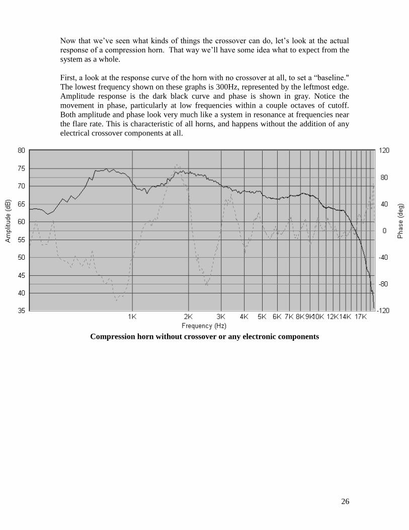
Now that we’ve seen what kinds of things the crossover can do, let’s look at the actual
response of a compression horn. That way we’ll have some idea what to expect from the
system as a whole.
First, a look at the response curve of the horn with no crossover at all, to set a “baseline."
The lowest frequency shown on these graphs is 300Hz, represented by the leftmost edge.
Amplitude response is the dark black curve and phase is shown in gray. Notice the
movement in phase, particularly at low frequencies within a couple octaves of cutoff.
Both amplitude and phase look very much like a system in resonance at frequencies near
the flare rate. This is characteristic of all horns, and happens without the addition of any
electrical crossover components at all.
Compression horn without crossover or any electronic components
27
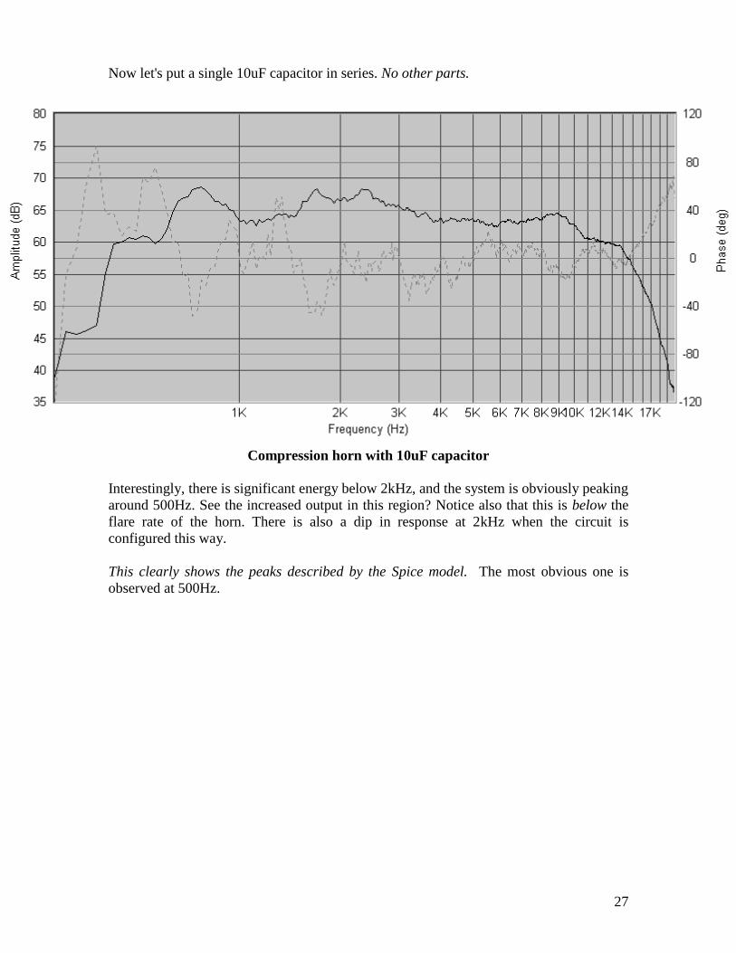
Now let's put a single 10uF capacitor in series. No other parts.
Compression horn with 10uF capacitor
Interestingly, there is significant energy below 2kHz, and the system is obviously peaking
around 500Hz. See the increased output in this region? Notice also that this is below the
flare rate of the horn. There is also a dip in response at 2kHz when the circuit is
configured this way.
This clearly shows the peaks described by the Spice model. The most obvious one is
observed at 500Hz.
28
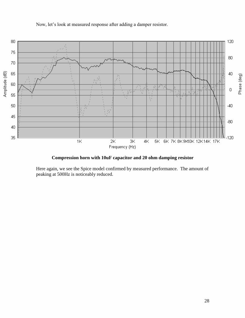
Now, let’s look at measured response after adding a damper resistor.
Compression horn with 10uF capacitor and 20 ohm damping resistor
Here again, we see the Spice model confirmed by measured performance. The amount of
peaking at 500Hz is noticeably reduced.
29
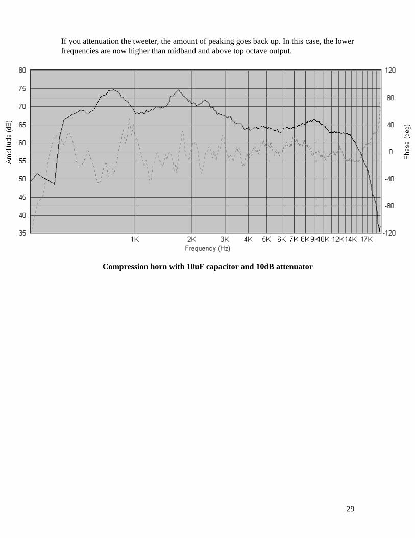
If you attenuation the tweeter, the amount of peaking goes back up. In this case, the lower
frequencies are now higher than midband and above top octave output.
Compression horn with 10uF capacitor and 10dB attenuator
30
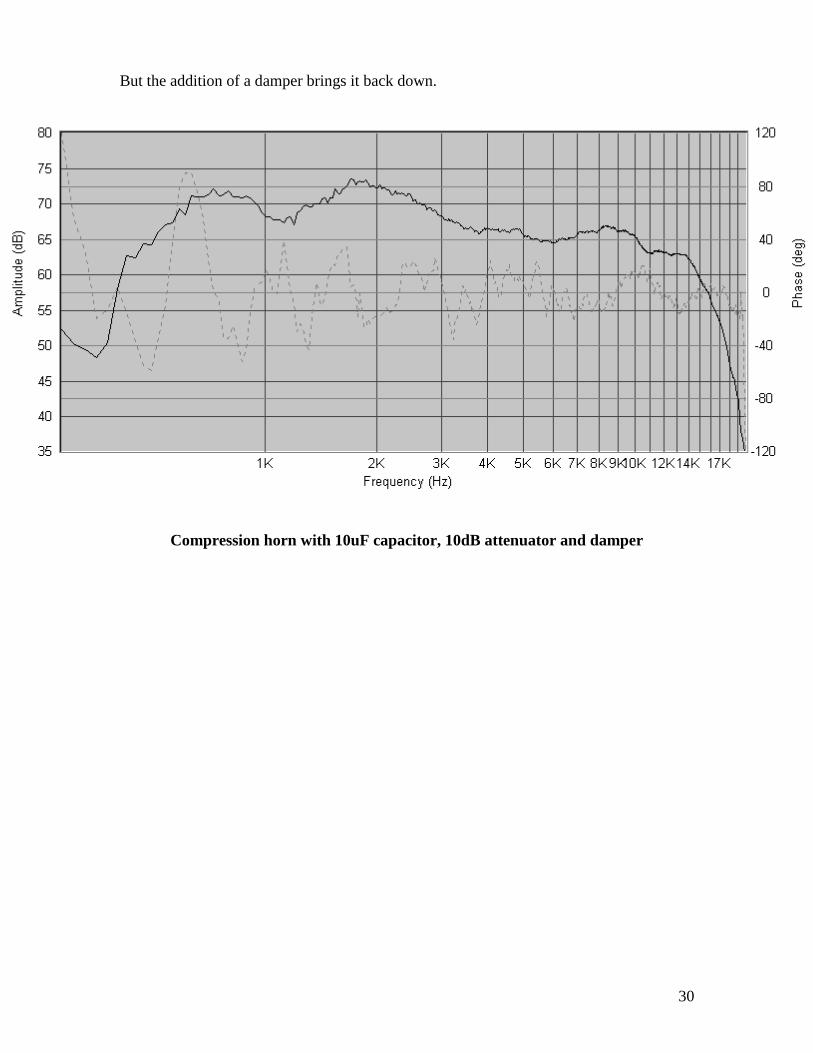
But the addition of a damper brings it back down.
Compression horn with 10uF capacitor, 10dB attenuator and damper
31
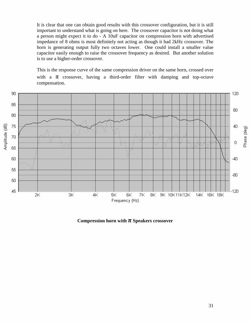
It is clear that one can obtain good results with this crossover configuration, but it is still
important to understand what is going on here. The crossover capacitor is not doing what
a person might expect it to do - A 10uF capacitor on compression horn with advertised
impedance of 8 ohms is most definitely not acting as though it had 2kHz crossover. The
horn is generating output fully two octaves lower. One could install a smaller value
capacitor easily enough to raise the crossover frequency as desired. But another solution
is to use a higher-order crossover.
This is the response curve of the same compression driver on the same horn, crossed over
with a π crossover, having a third-order filter with damping and top-octave
compensation.
Compression horn with π Speakers crossover
32
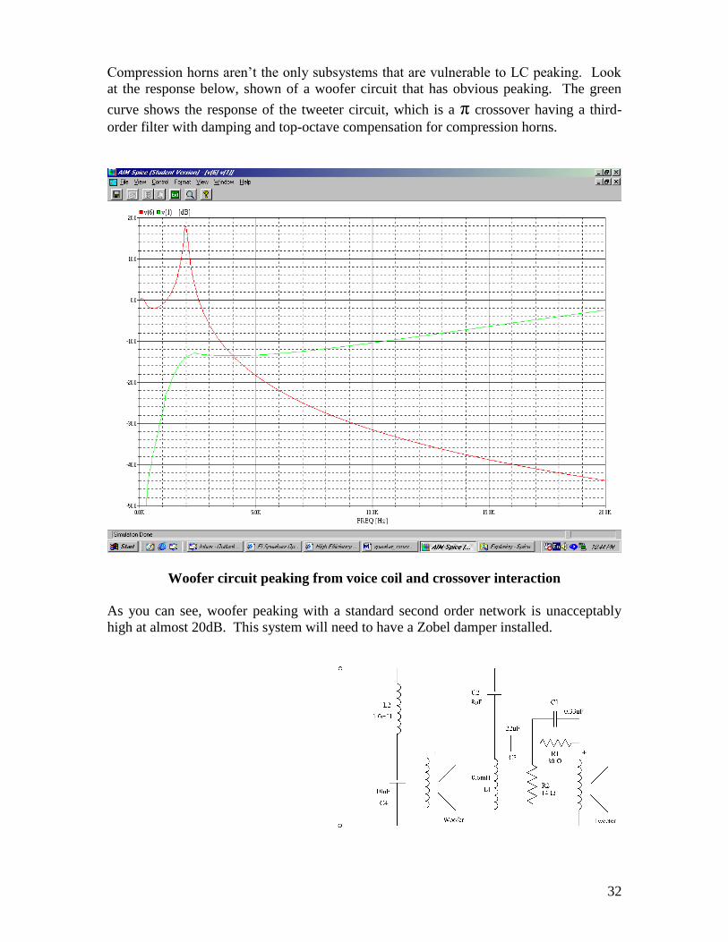
Compression horns aren’t the only subsystems that are vulnerable to LC peaking. Look
at the response below, shown of a woofer circuit that has obvious peaking. The green
curve shows the response of the tweeter circuit, which is a π crossover having a third-
order filter with damping and top-octave compensation for compression horns.
Woofer circuit peaking from voice coil and crossover interaction
As you can see, woofer peaking with a standard second order network is unacceptably
high at almost 20dB. This system will need to have a Zobel damper installed.
33
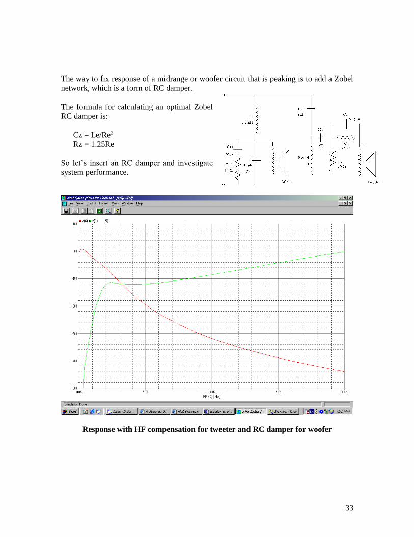
The way to fix response of a midrange or woofer circuit that is peaking is to add a Zobel
network, which is a form of RC damper.
The formula for calculating an optimal Zobel
RC damper is:
Cz = Le/Re2
Rz = 1.25Re
So let’s insert an RC damper and investigate
system performance.
Response with HF compensation for tweeter and RC damper for woofer
34
π Speakers
“Crossover Electronics 101”
Circuits and Response Graphs
35
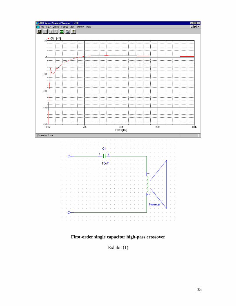
First-order single capacitor high-pass crossover
Exhibit (1)
36
First-order high-pass capacitor with damping resistor
Exhibit (2)
37
“First-order” high-pass crossover with series attenuation resistor
Exhibit (3)
38
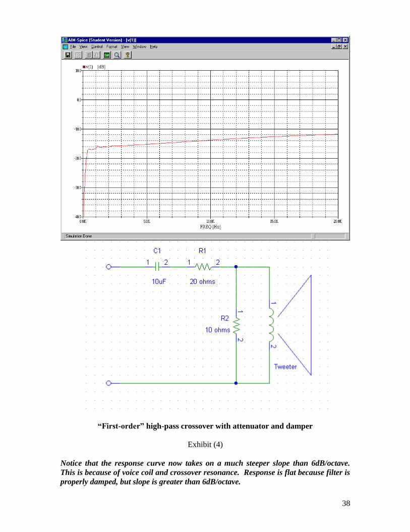
“First-order” high-pass crossover with attenuator and damper
Exhibit (4)
Notice that the response curve now takes on a much steeper slope than 6dB/octave.
This is because of voice coil and crossover resonance. Response is flat because filter is
properly damped, but slope is greater than 6dB/octave.
39
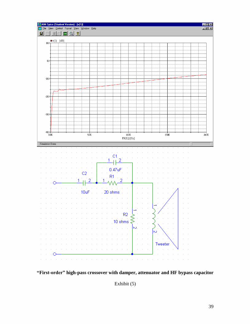
“First-order” high-pass crossover with damper, attenuator and HF bypass capacitor
Exhibit (5)
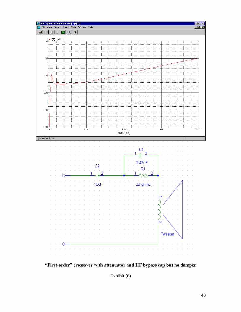
40
“First-order” crossover with attenuator and HF bypass cap but no damper
Exhibit (6)
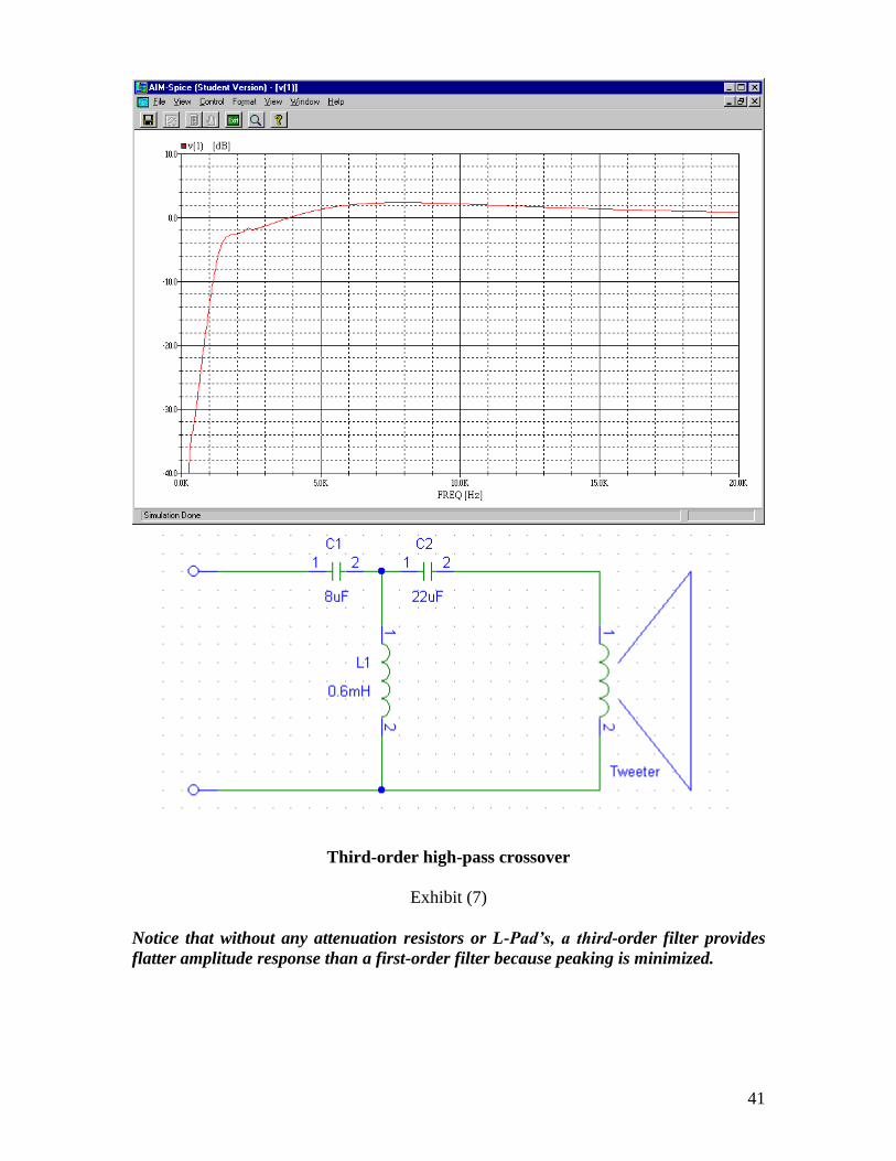
41
Third-order high-pass crossover
Exhibit (7)
Notice that without any attenuation resistors or L-Pad’s, a third-order filter provides
flatter amplitude response than a first-order filter because peaking is minimized.
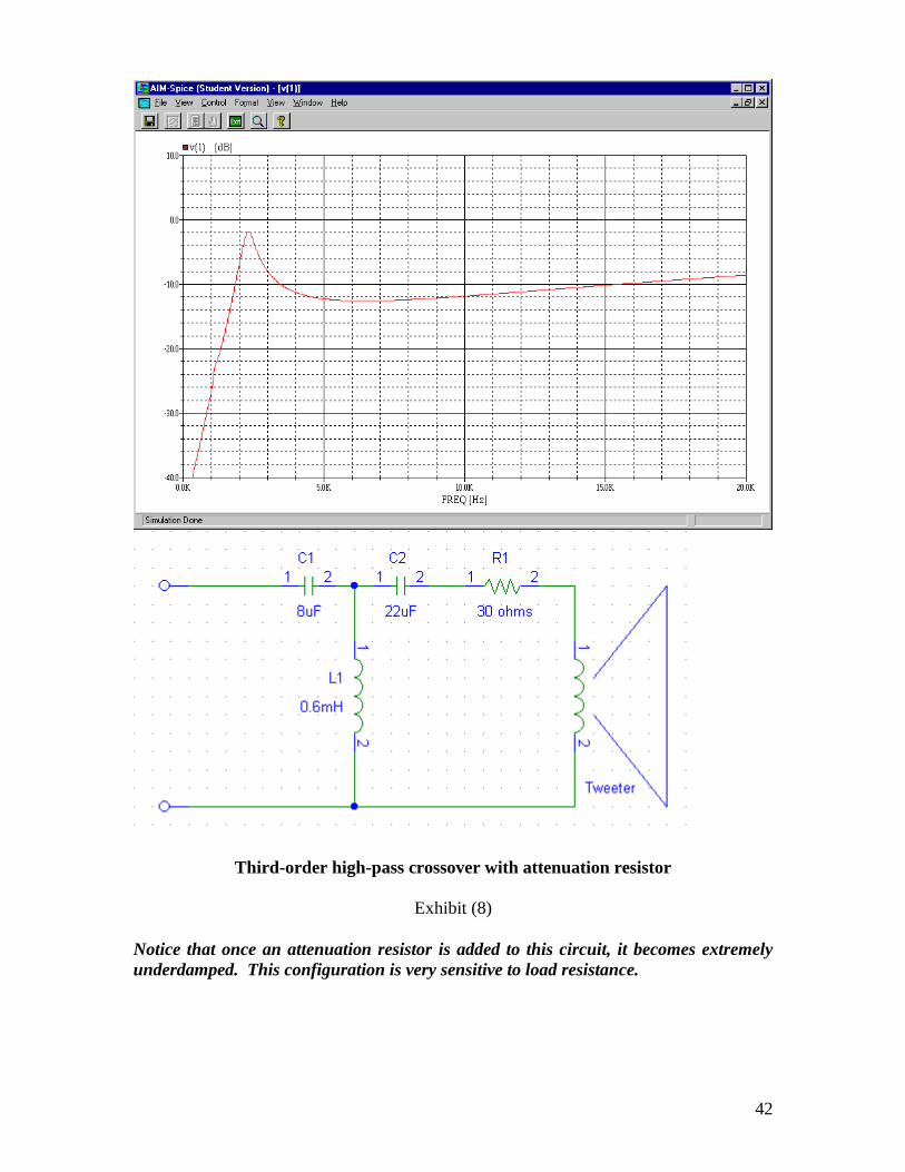
42
Third-order high-pass crossover with attenuation resistor
Exhibit (8)
Notice that once an attenuation resistor is added to this circuit, it becomes extremely
underdamped. This configuration is very sensitive to load resistance.
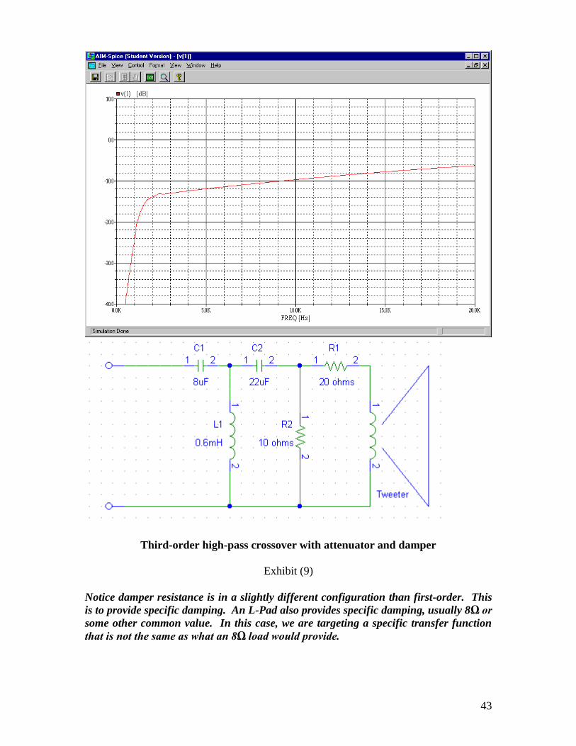
43
Third-order high-pass crossover with attenuator and damper
Exhibit (9)
Notice damper resistance is in a slightly different configuration than first-order. This
is to provide specific damping. An L-Pad also provides specific damping, usually 8Ω or
some other common value. In this case, we are targeting a specific transfer function
that is not the same as what an 8Ω load would provide.
44
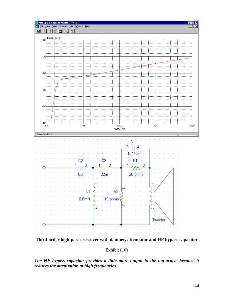
Third-order high-pass crossover with damper, attenuator and HF bypass capacitor
Exhibit (10)
The HF bypass capacitor provides a little more output in the top-octave because it
reduces the attenuation at high frequencies.
45
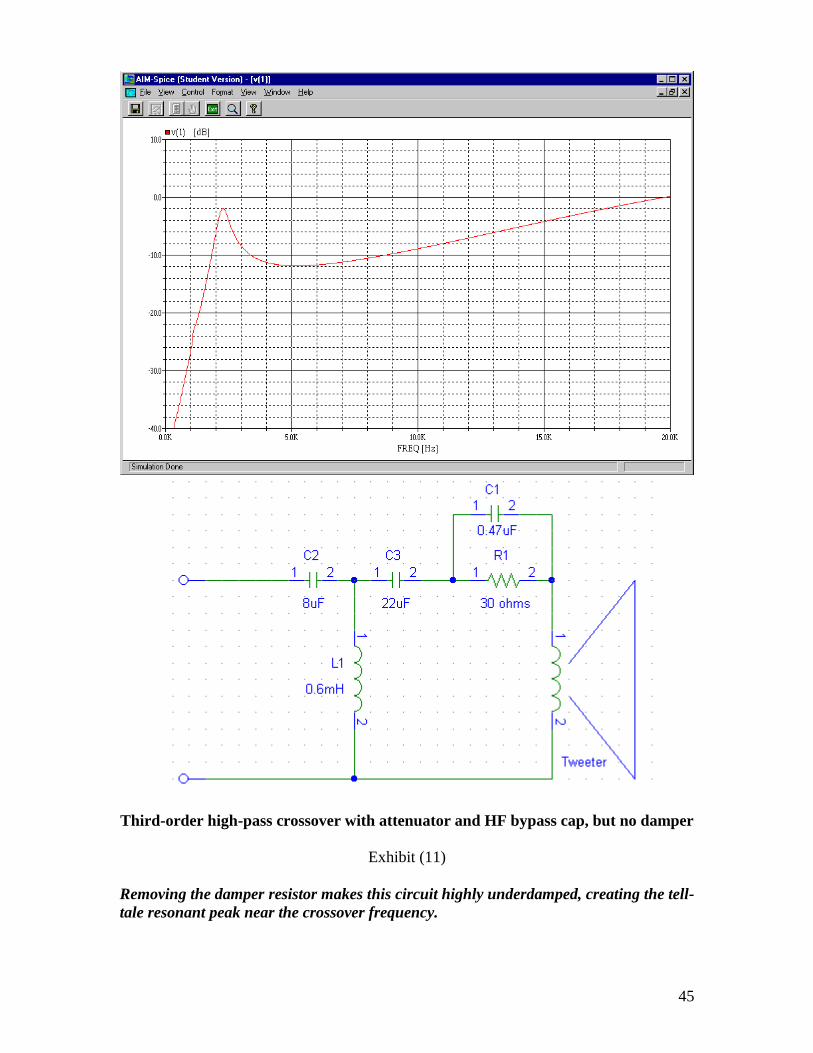
Third-order high-pass crossover with attenuator and HF bypass cap, but no damper
Exhibit (11)
Removing the damper resistor makes this circuit highly underdamped, creating the tell-
tale resonant peak near the crossover frequency.
46
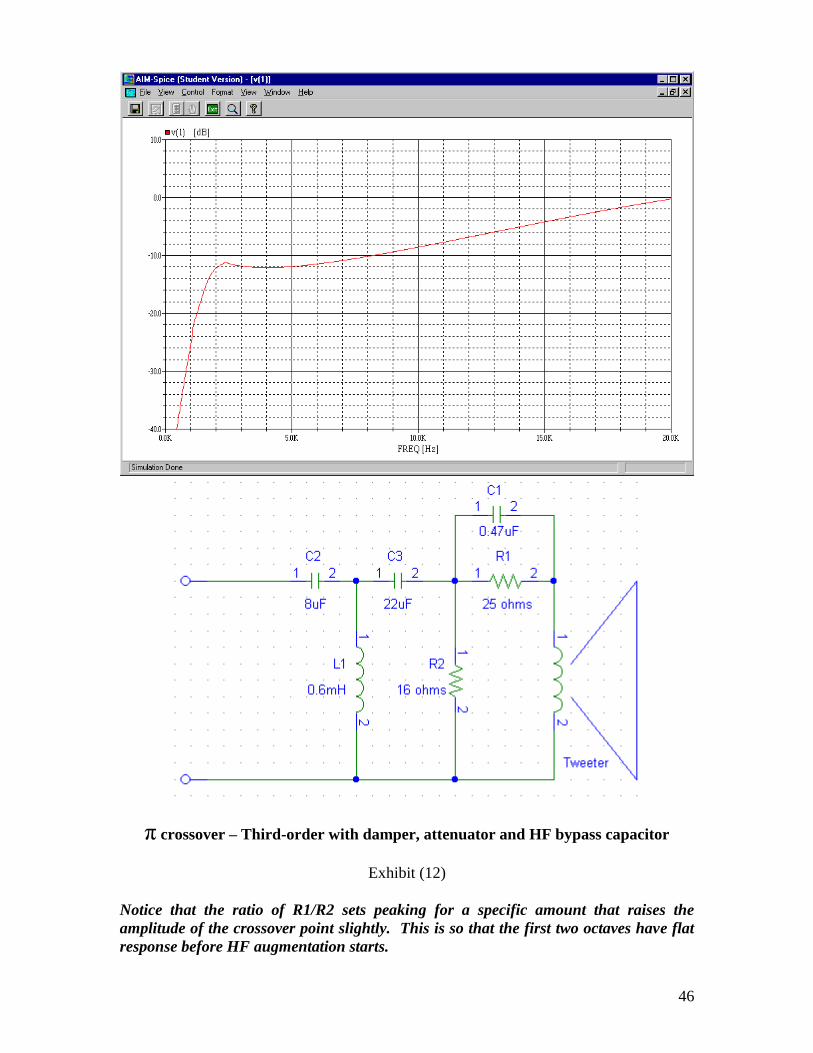
π crossover – Third-order with damper, attenuator and HF bypass capacitor
Exhibit (12)
Notice that the ratio of R1/R2 sets peaking for a specific amount that raises the
amplitude of the crossover point slightly. This is so that the first two octaves have flat
response before HF augmentation starts.
47
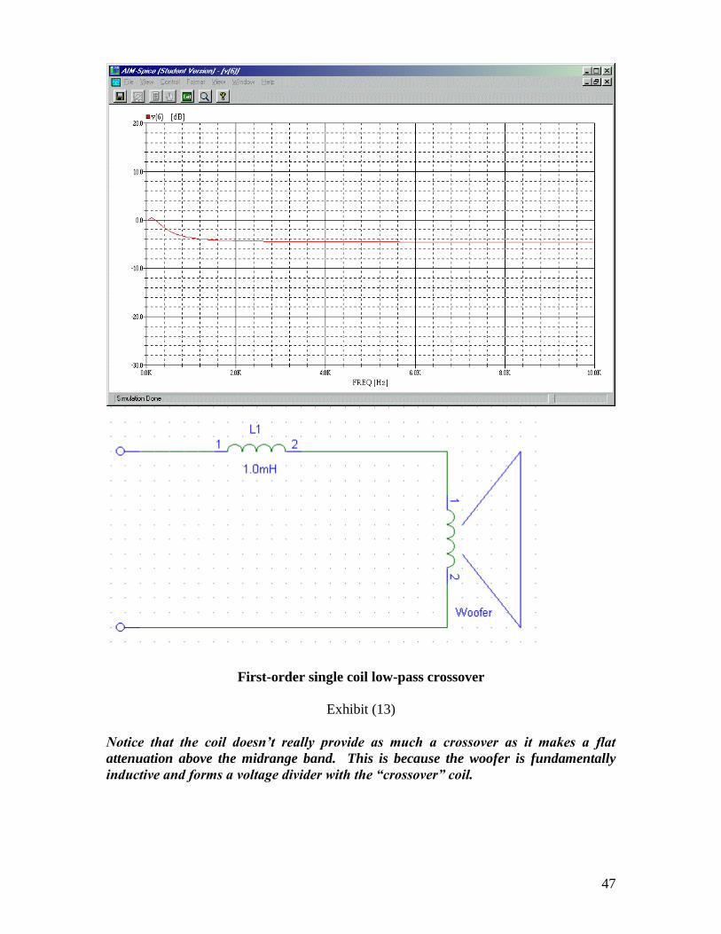
First-order single coil low-pass crossover
Exhibit (13)
Notice that the coil doesn’t really provide as much a crossover as it makes a flat
attenuation above the midrange band. This is because the woofer is fundamentally
inductive and forms a voltage divider with the “crossover” coil.
48
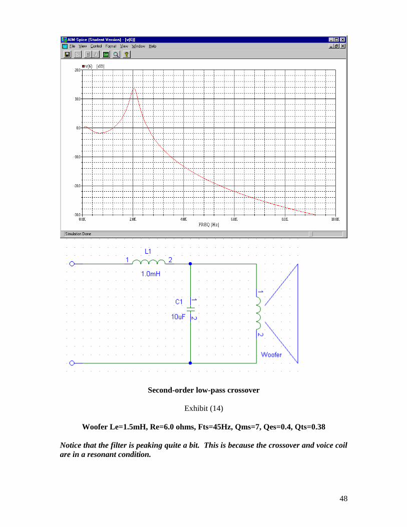
Second-order low-pass crossover
Exhibit (14)
Woofer Le=1.5mH, Re=6.0 ohms, Fts=45Hz, Qms=7, Qes=0.4, Qts=0.38
Notice that the filter is peaking quite a bit. This is because the crossover and voice coil
are in a resonant condition.
49
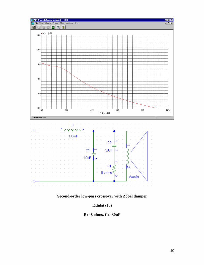
Second-order low-pass crossover with Zobel damper
Exhibit (15)
Rz=8 ohms, Cz=30uF
50
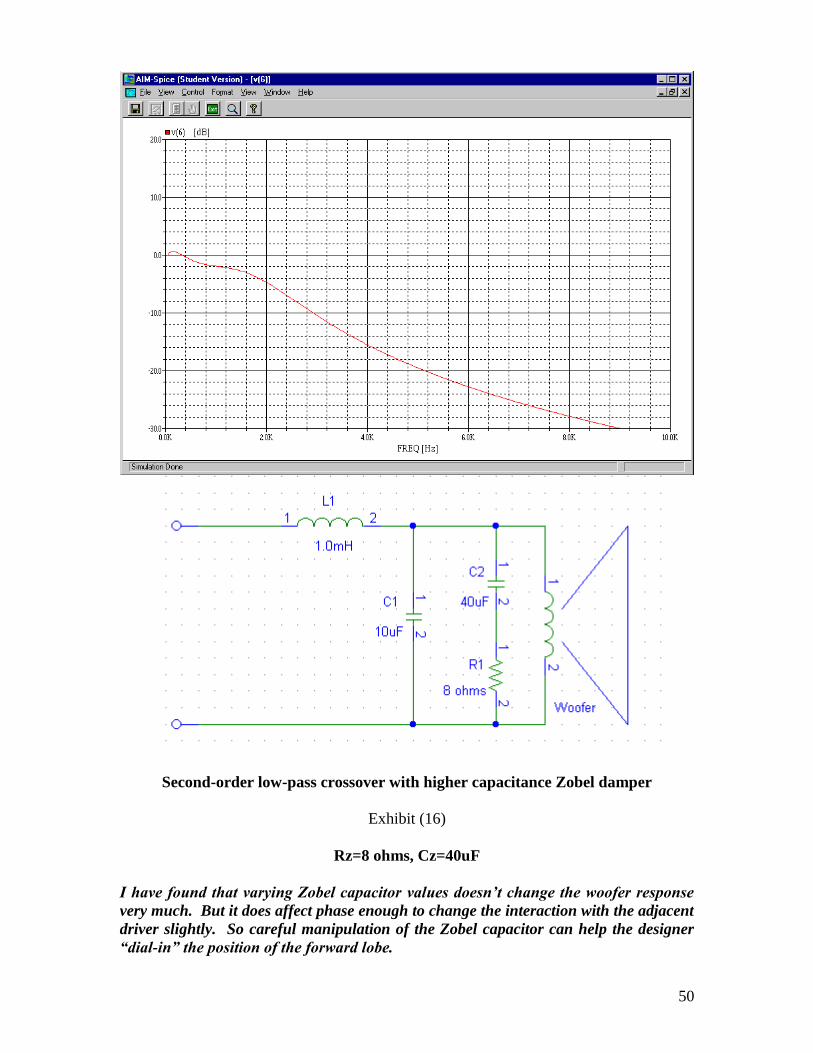
Second-order low-pass crossover with higher capacitance Zobel damper
Exhibit (16)
Rz=8 ohms, Cz=40uF
I have found that varying Zobel capacitor values doesn’t change the woofer response
very much. But it does affect phase enough to change the interaction with the adjacent
driver slightly. So careful manipulation of the Zobel capacitor can help the designer
“dial-in” the position of the forward lobe.