
Λ» OPTIONS FOR mm Ρ mßmw m
56
ì Wk EUR 4 Î 0 9 e iftppl ÉiilSiÊ EUROPEAN ATOMIC ENERGY COMMUNITY EURATOM SM %m 'Κ'ΓΗΗΙ Λ» OPTIONS FOR ^ l i Ä l l l l ^ A 250 MWe ORGEL PROTOTYPE PLANT mm m Ρ ORIENTATION STUDY ¡SilS by mm mßmw A. DECRESSIN, F. LAFONTAINE, J. NOAILLY and P. TAUCH JPÄP
Transcript of Λ» OPTIONS FOR mm Ρ mßmw m
ì
Wk EUR 4 Î 0 9 e
iftppl ÉiilSiÊ
EUROPEAN ATOMIC ENERGY COMMUNITY EURATOM
SM %m
'Κ'ΓΗΗΙ
Λ» OPTIONS FOR
^ l i Ä l l l l ^ A 250 MWe ORGEL PROTOTYPE PLANT mm
m Ρ ORIENTATION STUDY ¡SilS
by
mm mßmw
A. DECRESSIN, F. LAFONTAINE, J. NOAILLY and P. TAUCH
J P Ä P
au IPfipSlii IM»
Make any warranty or representation, express or implied, with respect to the accuracy, completeness, or usefulness of the information contained in this document, or that the use of any information, apparatus, method, or process disclosed in this document may not infringe privately owned rights; or
mm 'Vc .'IPS
This report is on sale at the addresses listed on cover page 4
føjfefflj _
at the price of FF 7. FB 70.— DM 5.60 Lit. 870 Fl. 5.10 U
When ordering, please quote the EUR number and the title, which are indicated on the cover of each report.
Wi?
8s af its tfHJWisg« SÎSÏKKÎBP Mmm nMm-ml^^ Ψ&
This document was reproduced on the basis of the t
Mm liiliÉliii^É' .A
teP<!i™ ilifil
ÍPÉIIÉ Iipllt!«*«!» lil m Ém íBãhmSmàm » Êmëaalmsmïmmèaa
EUR 4209 e OPTIONS FOR A 250 MWe ORGEL PROTOTYPE PLANT ORIENTATION STUDY by A. DECRESSIN, F. LAFONTAINE, J. NOAILLY and P . TAUCH
European Atomic Energy Community - EURATOM ORGEL Program Joint Nuclear Research Center - Ispra Establishment (Italy) ORGEL Project Luxembourg, April 1969 - 50 Pages - 10 Figures - FB 70
A comparison is made for three different ORGEL power plants of 250 MWe gross, in order to illustrate different possibilities of this string. One plant is working on natural uranium, two other plants on slightly enriched uranium. Fuel is always uranium carbide, the organic coolant is of the OM-2 type. The fuel management foreseen is a bidirectional one with the reactor being on -load.
The three reactors have been optimized taking into account a certain number of technological restrictions which are due to the actual state of development of the ORGEL string.
EUR 4209 e OPTIONS FOR A 250 MWe ORGEL PROTOTYPE PLANT ORIENTATION STUDY by A. DECRESSIN, F. LAFONTAINE, J. NOAILLY and P. TAUCH
European Atomic Energy Community - EURATOM ORGEL Program Joint Nuclear Research Center - Ispra Establishment (Italy) ORGEL Project Luxembourg, April 1969 - 50 Pages - 10 Figures - FB 70
A comparison is made for three different ORGEL power plants of 250 MWe gross, in order to illustrate different possibilities of this string. One plant is working on natural uranium, two other plants on slightly enriched uranium. Fuel is always uranium carbide, the organic coolant is of the OM-2 type. The fuel management foreseen is a bidirectional one with the reactor being on -load.
The three reactors have been optimized taking into account a certain number of technological restrictions which are due to the actual state of development of the ORGEL string.
The characteristics of the three plants are given and discussed in detail as well as the hypothesis adopted for the calculations.
The characteristics of the three plants are given and discussed in detail as well as the hypothesis adopted for the calculations.
EUR 4 2 0 9 e
EUROPEAN ATOMIC ENERGY COMMUNITY - EURATOM
OPTIONS FOR A 250 MWe ORGEL PROTOTYPE PLANT
ORIENTATION STUDY
by
A. DECRESSIN, F. LAFONTAINE, J. NOAILLY and P. TAUCH
1969
ORGEL Program
Joint Nuclear Research Center Ispra Establishment - Italy
ORGEL Project
A B S T R A C T
A comparison is made for three different ORGEL power plants of 250 MWe gross, in order to illustrate different possibilities of this string. One plant is working on natural uranium, two other plants on slightly enriched uranium. Fuel is always uranium carbide, the organic coolant is of the OM-2 type. The fuel management foreseen is a bidirectional one with the reactor being on -load.
The three reactors have been optimized taking into account a certain number of technological restrictions which arc due to the actual state of development of the ORGEL string.
The characteristics of the three plants are given and discussed in detail as well as the hypothesis adopted for the calculations.
KEYWORDS
ORGEL REACTOR URANIUM CARBIDES POWER PLANTS ORGANIC COOLANT NATURAL URANIUM FUEL OPTIMIZATION URANIUM DESIGN ENRICHED MATERIALS
CONTENTS
Part I 1 . 1 . Introduction 1.2. Natural-uranium reactor (reactor A) 1.3· High-performance reactor (reactor B) 1.4". High-performance and intrinsically stable reactor
(reactor C) 1.5· Tables
Part II 11.1. Power balance 11.2. Reactor block 11.3· Neutron physics II.4. Thermohydraulic performances II.5· Steam system II.6. Organic coolant and coolant purification system II.7· Reactor stability II.8. Economy of the plants
III. References
IV. Figures

- 5 -
PART I
Options for a prototype
1.1. Introduction
Many choices are open when the engineer is designing the core of a 250 MWe ORGEL prototype* Among them, one presents in this report the main features of three reactors as illustration of three different tendencies:
a natural-uranium reactor (reactor A); a high-performance reactor (reactor B); a high-performance and intrinsically stable reactor (reactor C).
These three reactors have been optimized taking into account a certain number of restrictions which are due to the actual state of development of the ORGEL string.
The three reactors are equipped with a G-l8 fuel element of the structured type (central rod); it is on that type of fuel element that the development effort is actually focused.
The coolant channel is of the gas-insulated type with SAP pressure tube. An exchange with zirconium-based pressure tube would not alter the main characteristics of these three reactors.
The design of the cell (fuel element and channel assembly) of these three reactors has been done in such a way as to render the three solutions technologically as similar as possible· Nevertheless, the fuel element performances
(*) Manuscript received on I4 January 1969·
- 6
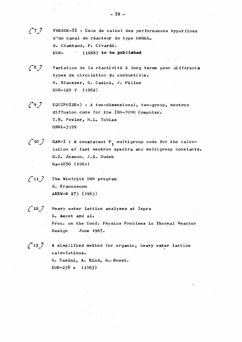
differ strongly by the couple of values relating to conductivity integral and burn-up, which however are well within the technological limits of the fuel (see Fig. 0, extracted from the prototype tender).
These three reactors have many common features: vertical axis, on-load bidirectional fuel cycle, OM-2 organic cooling, extraction of high boilers by distillation, etc., which are given with their general characteristics in the tables of Chapter 1.5»
1.2 o Natural-uranium reactor (reactor A)
The ORGEL reactor is able to burn natural uranium. Earlier studies seem to demonstrate that, in such a case, the ideal fuel is not represented by a G-18 fuel bundle o Nevertheless, for the reason mentioned in I.I., this fuel type has been adopted for the study.
The fuel has been designed in order to minimize the quantity of absorbing material.
A maximum conductivity integral of 40 W/cm coupled with a pin diameter of about 1.5 cm (fuel section between 30 and 35 cm2) consents a maximum specific power of about 21 W/g, maintaining the coolant section/fuel section ratio per channel at a non-too-high figure, neighbouring 0.5·
The fuel section has been optimized on the strength of available experimental reactor physics data. The optimum
(l) Although the G-18 fuel bundle does not represent the optimum solution for the natural uranium concept, it represents the best compromise if one intendsto develop the natural and enriched ORGEL strings· This is the reason why the development effort is, to the present, focussed on ito
7 -
moderation ratio is nearly equal to l8.
The main characteristics of this reactor A are:
- Heavy water investment: 1 Τ/MWe - Average burn-up: 7,000 MWd/T - Net power plant efficiency: 30% - (Coolant outlet temperature in the neighbourhood of 360°C)
The result is a relatively high cost of electric power (fixed costs of about 0,90 milis/kWh due to direct and indirect
(l) investment in heavy water and fuel consumption costs (see Table l) of about 1.5 milis/kWh) (no fuel reprocessing).
It has to be noted that very similar performances are obtainable in a CANDU reactor or in an ORGEL reactor fed with Zirconium-alloy cladded UO fuel»
tit
Indeed, on one hand neutronic calculations indicate that in an A-type reactor the substitution of uranium carbide by uranium oxide and of SAP by Zr-2,5 Nb determines a 2,000 MWd/T loss in burn-up; on the other hand, WR-I UO /Zr-2,5 Nb reference fuel operates with a conductivity 2 integral of 36 W/cm having attained a 10,000 MWd/T burn-up at
(2) the end of 1967· Finally, admitting a $6o/kg fuel cost , it appears that a burn-up of only about 5)500 MWd/T is sufficient to determine fuel consumption costs in the order of 1.5 milis/kWh.
To improve reactor performance, there is only one possibility: enrich fuel in order to increase burn-up and/ or diminish investment.
(1) Heavy water: $20/lb; indirect investment estimated at 35% of direct investment·
(2) See AECL 2534, "Trends in Atomic Power Costs".
8 -
Should fuel be enriched with the sole purpose of increasing burn-up, these would be the results:
Enrichment Burn-up Fuel cost Fuel consumption
TABLE
wt % - U-235 MWd/T Vkg
milis/kWh
1
0,71 7,000 75 1.47
0,93 14,000 100 0.97
1,14 20,500 120 0.80
The reduction in fuel consumption costs is considerable; it is of interest to note that it can also be achieved with UO -fuel clad in zirconium alloy.
•A
Fuel enrichment may be envisaged in order to lower substantially investment. Then, it is necessary to increase strongly the heat output per channel and hence the linear heat rating of the fuel rods, if one sticks to the G-l8 fuel element
.(1) concept
To minimize absorbing material in the cell is no longer a goal; on the contrary, it is necessary to fin the fuel cladding and to increase the coolant section of the fuel element in order to extract as much heat as possible.
In this run to high linear heat ratings, one parameter remains free: the diameter of the fuel rods. Two fuel elements, each one designed for a maximum conductivity integral of 90 W/cm and with identical thermomechanical stresses, are illustrating this freedom (Table 2·): the first with the same fuel rods as those of the A reactor, the second with thicker fuel rods.
(1) Such a thing seems difficult with UO fuel, so one resorts to a SAP-clad UC fuel.
9 -
TABLE 2
Rod diameter (cm)
1.5 1.8
Coolant section to fuel section ratio
1 0.65
Fuel section (cm2)
33 47-5
1.3· High-performance reactor (reactor B)
The concept of this reactor is both to minimize heavy water and fuel inventory and to maximize burn-up. This determines a choice of pin-diameter of about 1.5 cm - identical as with station A - coupled with a 90 W/cm conductivity integral (hence an organic/fuel ratio = l) and a heavy water/fuel ratio in the neighbourhood of l6.
In such conditions, it is possible to reduce heavy water investment to 0·46 Τ/MWe and fuel investment to 0.17 τ/MWe and yet obtain 15,000 MWd/T burn-up; fixed costs pertaining to direct and indirect heavy water investment thus attain 0.4 milis/kWh, and fuel consumption costs 1.1 milis/kWh, a definite improvement over natural uranium.
The counterpart consists in:
1) A close vicinity between the fuel performances and the theoretical technological limits of UC-SAP fuel (Fig. 0 - see also doc. 2 in the prototype tender ledger)
1 2) A greater amount of energy deposited in the organic
coolant: 0.5596 instead of 0,37% of total fission energy.
3) A slight fuel enrichment of about l.l4# in U-235·
4) The impossibility of operating this reactor with
natural uranium.
10
1.4. High-performance and intrinsically stable reactor (reactor C)
The concept of this reactor is to obtain inherent stability and yet preserve to the utmost the economic features of a high-performance reactor.
For this purpose, as compared with reactor A, one has increased, not only the linear heat rating of the fuel rods, but also the diameter of these in order to minimize the organic-to-fuel
( l) ratio (the de-stabilizing effect is essentially due to the presence of organic), while the moderation ratio has been reduced in a very marked measure (down to value 9) in order to increase the organic's moderating power in regard of that of heavy water,
(2) and likewise resonance absorption and thus the Doppler effect. According to the latest buckling measurements, it appears that ensuing reactivity loss is relatively low for such large fuel sections (pi 50 cm2) / Ref. 1 /.
Finally, a preliminary design-study shows that a moderation ratio as low as 9 can be obtained with clusters having a fuel section of about 50 cm2, but that this would not be possible with smaller fuel sections.
A fuel section greater than 50 cm2 was disregarded here:
1) because buckling measurements for such large sections are not yet available;
2) because the diameter of SAP pressure tubes would be too much above that of tubes now in production;
3) because an upper 90 W/cm-limit has been set for the conductivity integral (due to the lack of experiments);
(1) In reactor Β instead, pin-diameter has been maintained constant ν thus allowing an increase in specific fuel power but with an ensuing deterioration in the organic/fuel ratio.
(2) The increase in resonance absorption implies an increase in the initial conversion factor - from 0.6 to 0.7 - and thus explains the economic equivalence in the plant Β and C fuel cycles. See further on.
11 -
4) because of a limit of l8 (or 19) has been set for the number of rods per fuel cluster.
As opposed to reactor B, this reactor offers the following advantages: a -2.2 pcm/% power negative power coefficient instead of a positive +1 pcm/% power , a lower void coefficient at equilibrium, a slight decrease in heavy water investment (0.40 x/MWe instead of 0.46 T/MWe), a slight decrease of power absorbed by the organic coolant (0.47% of total fission power instead of 0.55%) and a slight increase of plutonium concentration in irradiated fuel.
On the other hand, there are the following disadvantages: slight increase in fuel investment (0.24 T/MWe instead of 0.17 T/MWe and a slight decrease in burn-up (13,300 MWd/T instead of 15,000 MWd/T).
These differences offset one another in terras of cost. Economically, these two reactors are nearly equivalent, with a slight advantage for reactor B.( see also footnote on page 32).
One should not however loose sight of the fact that, (2) although reactor C is stable , it does not offer a wide safety
margin in relation to its stability-limit (zero-power coefficient) and that, furthermore, the organic's temperature coefficient is positive. A detailed analysis is necessary in order to assess how the layout of the control equipment of reactor C can profit from the negative power coefficient.
(1) Reactor A's power coefficient is also positive, slightly more than 1 pcm/% power.
(2) At least according to the temperature coefficients calculated by PLUTHARCO ¿Ref. ¿/.
12 -
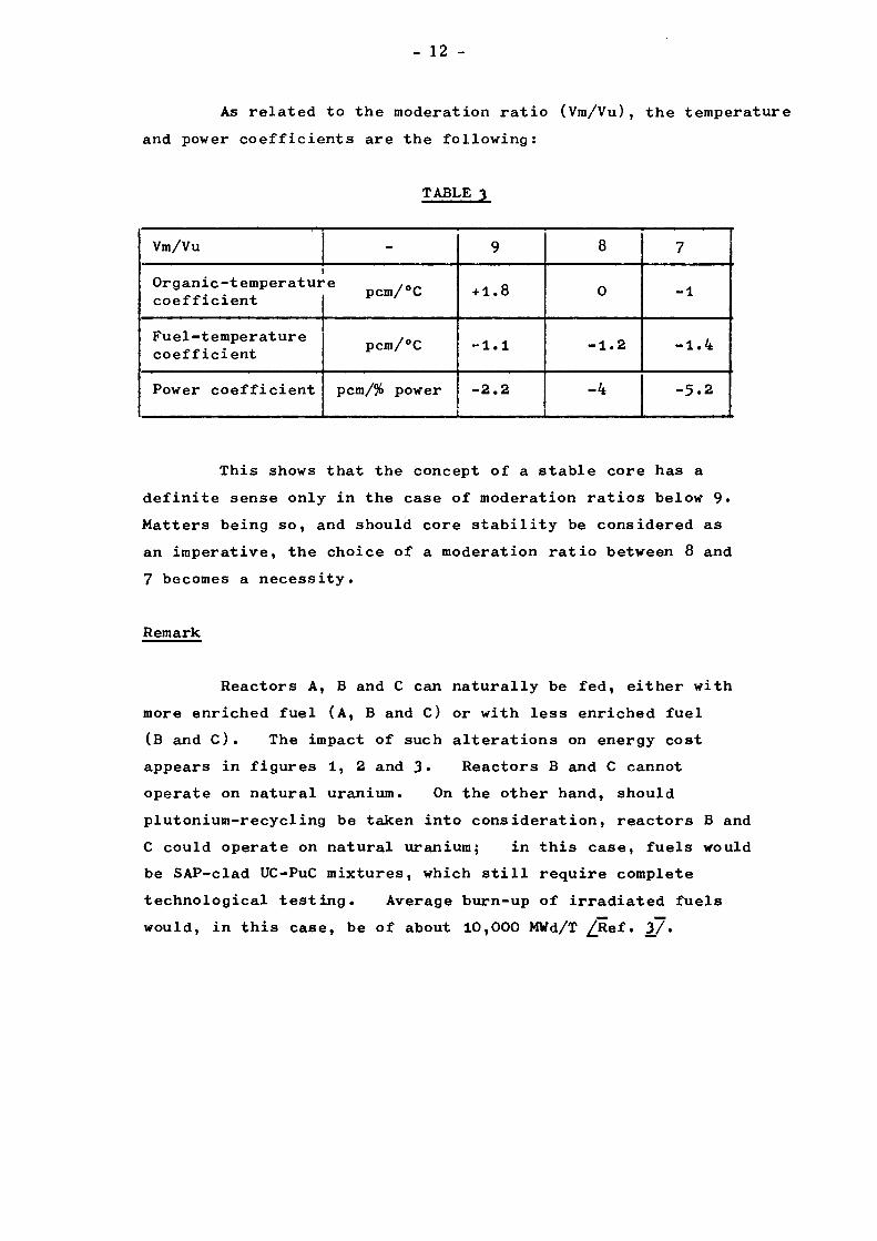
As related to the moderation ratio (Vm/Vu), the temperature and power coefficients are the following:
TABLE 3
Vm/Vu
Organic-temperatur coefficient
Fuel-temperature coefficient
Power coefficient
pcm/°C
pcm/°C
pcm/% power
9
+ 1.8
-1.1
-2.2
8
0
-1.2
-4
7
-1
-1.4
-5.2
This shows that the concept of a stable core has a definite sense only in the case of moderation ratios below 9« Matters being so, and should core stability be considered as an imperative, the choice of a moderation ratio between 8 and 7 becomes a necessity.
Remark
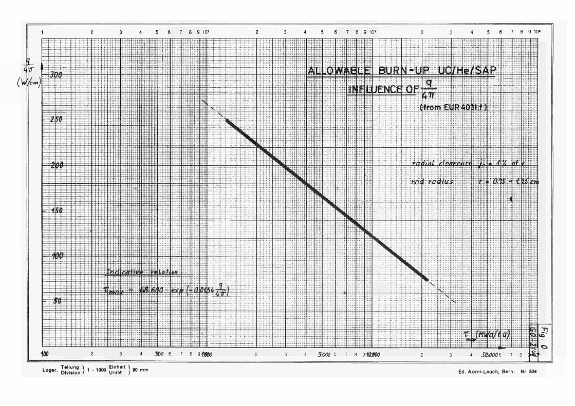
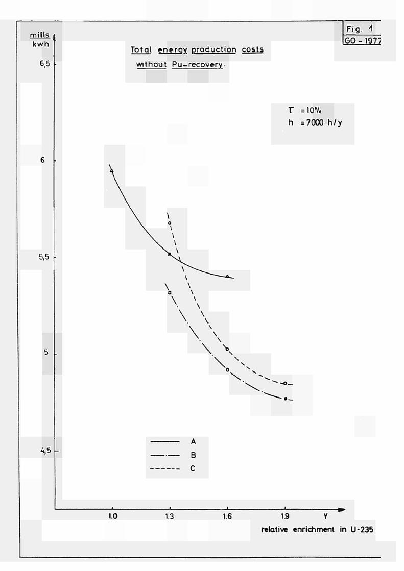
Reactors A, B and C can naturally be fed, either with more enriched fuel (A, B and C) or with less enriched fuel (B and C ) . The impact of such alterations on energy cost appears in figures 1, 2 and 3· Reactors B and C cannot operate on natural uranium. On the other hand, should plutonium-recycling be taken into consideration, reactors B and C could operate on natural uranium; in this case, fuels would be SAP-clad UC-PuC mixtures, which still require complete technological testing. Average burn-up of irradiated fuels would, in this case, be of about 10,000 MWd/T ¿Ref. 3/·
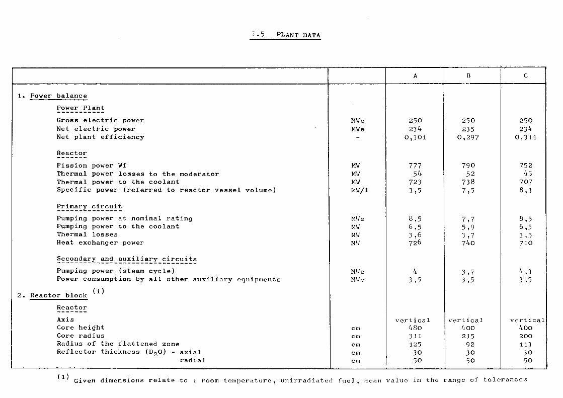
1.5 PLANT DATA
1.
2.
Power balance Power Plant Gross electric power Net electric power Net plant efficiency
Reactor Fission power Wf Thermal power losses to the moderator Thermal power to the coolant Specific power (referred to reactor vessel volume)
Primary circuit Pumping power at nominal rating Pumping power to the coolant Thermal losses Heat exchanger power
Secondary and auxiliary circuits Pumping power (steam cycle) Power consumption by all other auxiliary equipments
Reactor block Reactor Axis Core height Core radius Radius of the flattened zone Reflector thickness ( D Q O ) - axial
radial
MWe MWe -
MW MW MW kW/l
MWe MW MW MW
MWe MWe
cm cm cm cm cm
A
250 234
0,301
777 54
723 3,5
8,5 6,5 3,6 726
4 3,5
vertical 480 311 125 30 50
Β
250 235
0,297
790 52
738 7,5
7,7 5,9 3,7 740
3,7 3,5
vertical 400 215 92 30 50
C
25Ο 234
0,311
752 45
707 8,3
8,5 6,5 J 1 > 710
'i,3 3,5
vertical 400 200 113 30 50
(1) Given dimensions relate to : room temperature, unirradiated fuel, mean value in the range of tolerances
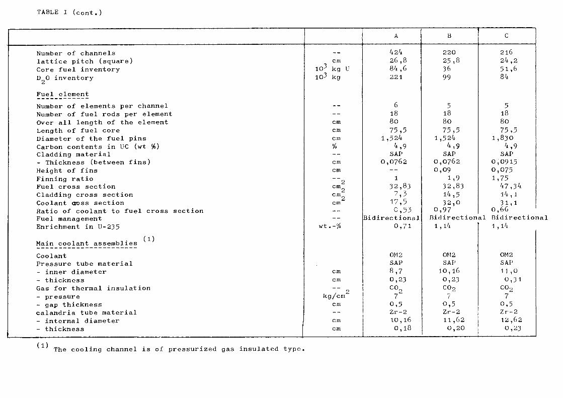
TABLE I (cont.)
Number of channels
lattice pitch (square)
Core fuel inventory
D O inventory
Fuel element
Number of elements per channel
Number of fuel rods per element
Over all length of the element
Length of fuel core
Diameter of the fuel pins
Carbon contents in UC (wt %) Cladding material
- Thickness (between fins)
Height of fins
Finning ratio
Fuel cross section
Cladding cross section
Coolant cross section
Ratio of coolant to fuel cross section
Fuel management
Enrichment in U-235
, ·, · d) Main coolant assemblies
Coolant
Pressure tube material
- inner diameter
- thickness
Gas for thermal insulation
- pressure
- gap thickness
calandria tube material
- internal diameter
- thickness
—
cm
103 kg U
103 kg
--
--
cm
cm
cm
% --cm
cm
~~2 cm
2 cm
2 cm
--
--
wt.-%
cm
cm
o kg/cm''
cm
--
cm
cm
A
424
26,8
84,6
221
6
18
80
75,5
1,524
4,9
SAP
0,0762
--
1
32 ,83
17,5
0,55
Bidirectional
0,71
0M2
SAP
8,7
0,23
C°2 7
0,5
Zr-2
10,16
0,18
■ ■ ■
Β
220
25,8
36
99
5
18
80
75,5
1,524
4,9 SAP
0,0762
0,09
1,9
32,83
14,5
32,0
0,97
C
216
24,2
51,6
84
5
18
80
75,5
1,830
4,9
SAP
0,0915
0,075
1,75
47,34
14,1
31,1
0,66
Bidirectional Bidirectioi
1,14
0M2
SAP
10,16
0,23
C0 2
7
0,5
Zr-2
11,62
0,20
1,14
0M2
SAP
11 ,ϋ 0,31 co2 7 0,5 Zr-2 12,62 0,23
(1) The cooling channel is of pressurized gas insulated type,
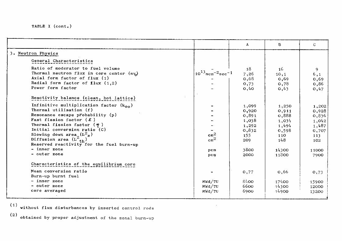
TABLE I (cont.)
3. Neutron Physics General Characteristics Ratio of moderator to fuel volume Thermal neutron flux in core center (nvj Axial form factor of flux (l) Radial form factor of flux (1,2) Power form factor
Reactivity balance (clean, hot lattice) Infinitive multiplication factor (k 0 0) Thermal utilisation (f) Resonance escape probability (p) Fast fission factor (£ ) Thermal fission factor (̂ ) Initial conversion ratio (C) Slowing down area (L g) Diffusion area (L .. ) Reserved reactivity for the fuel burn-up - inner zone - outer zone
Characteristics of the equilibrium core Mean conversion ratio Burn-up burnt fuel - inner zone - outer zone core averaged
13 o 10 ncm'^sec" -
--
------
cm2
cm2
pcm pcm
MWd/TU MWd/TU MWd/TU
A
18 1 7,26
0,68 0,73 0,40
1,099 0,920 0,891 1,038 1,292 0,832 155 209
3800 2000
0,77
8 4 OO 6600 6900
Β
16 ΙΟ,Ι 0,69 0,78 0,43
1,250 0,911 0,888 1,034 1,494 0,598 110 148
14300 II800
0,66
17400 143ΟΟ 14900
C
9 6,1 0,69 0,86 0,47
1,202 0,928 0,836 1,042 1,487 0,707 113 102
11000 7900
0,73
15900 12000 ! I32OO
i i
(1)
(2) without flux disturbances by inserted control rods
obtained by proper adjustment of the zonal burn-uo
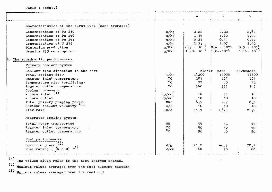
TABLE I (cont.)
4.
Characteristics of the burnt fuel (core averaged) Concentration of Pu 239 Concentration of Pu 240 Concentration of Pu 24l Concentration of U 235 Plutonium production Uranium 235 consumption
Thermohydraulic performances Primary coolant system Coolant flow direction in the core Total coolant flow Reactor inle* temperature Temperature rise (orificing) Reactor outlet temperature Coolant pressure - core inlet '1' - core outlet Total primary pumping power. Maximum coolant velocity Flow rate
Moderator cooling system Total power transported Reactor inlet temperature Reactor outlet temperature
Fuel performances (2) Specific power ' . .
Fuel rating ( Jk d θ) (3 '
g/kg g/kg g Ag g/kg
g/KWh g/KWh
t/hr °C °C °C
kg/cm2 kg/cm
MWe m/s
kg/s
MW °C °C
V/g li/cm
A
2,22 1,19 0,21 2,21
0,7 . 10~J 1,40. 10" 1
singl 14200 283 77
360
16 10
8,5 10
15,9
54 50 80
21,2 40
B
2,22 1,80 0,33 2,07
0,4 . 10-4 i,o4.io-4
C
2,61 1,99 0,4l 2,62
0,5 . io-£ i,i4. 10
e pass - downwards i4ooo 275 80
355
15 10 7,7 10
28,3
52 50 80
46,7 90
15300 293 72
365
16 10
8,5 10
2 7 , 2
45 50 80
28,2 80
(1) (2) (3)
The values given refer to the most charged channel Maximum values averaged over the fuel element section Maximum values averaged over the fuel rod
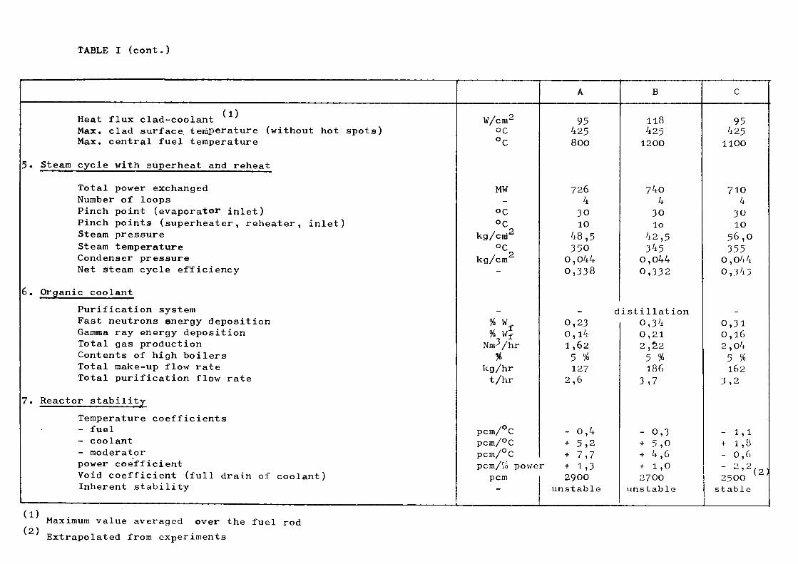
TABLE I (cont.)
5·
6.
7.
(1) Heat flux clad-coolant Max. clad surface temperature (without hot spots) Max. central fuel temperature
Steam cycle with superheat and reheat
Total power exchanged Number of loops Pinch point (evaporator inlet) Pinch points (superheater, reheater, inlet) Steam pressure Steam temperature Condenser pressure Net steam cycle efficiency
Organic coolant Purification system Fast neutrons energy deposition Gamma ray energy deposition Total gas production Contents of high boilers Total make-up flow rate Total purification flow rate
Reactor stability Temperature coefficients - fuel - coolant - moderator power coefficient Void coefficient (full drain of coolant) Inherent stability
W/cm2
oc °C
MW -
OC °C
kg/cnj2
°C kg/cm
-
-% w % Wf
Nm3/hr %
kg/hr t/hr
pcm/°C pcm/°C pcm/°C
A
95 425 800
726 4
30 10
48,5 350
0,044 0,338
d 0,23 0,l4 1,62 5 % 127
2,6
- 0,4 + 5,2 + 7,7
pcm/% power + 1,3 pcm -
2900 unstable
Β
118 425 1200
740 4
30 lo
42,5 345 0,044 0 , 3 3 2
istillation 0,34 0,21 2,22 5 % 186
3,7
- 0,3 + 5,0 + 4,6 + 1,0 27OO
unstable
C
95 425 1100
710 4
3 0 10
5 6 , 0 355
0,044 0,345
_ 0,31 0,16 2,04 5 % 162
3,2
- 1,1 + 1,8 - 0,6 - 9 9 ' (2) 25OO
stable
(1) (2)
Maximum value averaged over the fuel rod Extrapolated from experiments
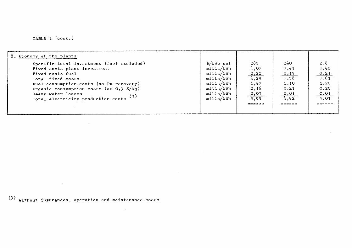
TABLE I (cont.)
, Economy of the plants Specific total investment (fuel excluded) Fixed costs plant investment Fixed costs fuel Total fixed costs Fuel consumption costs (no Pu-recovery) Organic consumption costs (at 0,3 $/kg) Heavy water losses , . Total electricity production costs
$/kWe net milis/kWh milis/kWh milis/kWh milis/kWh milis/kWh milis/kWh milis/kWh
285 4 0 4 1 0 0
,07 , 2 2 , 2 9 , 47 ,16 .03
5,95
2' 3 0 3 1 0 0
¿ 0
, 43 »15 , 5 3 , 1 0 , 23 , 0 1
4 , 9 2
0
3 0 3 1 0 0 5
38 , 4 0 , 2 1 , 6 1 , 2 0 , 2 0 , 0 1 , 03
(3) Without insurances, operation and maintenance costs
19 -
PART II
Remarks with respect to the plant data of chapter 1.5
II.1. Power balance
The net electrical output is slightly different for the various plants and has been obtained by stipulating a fixed gross electric power of 250 MWe for all plants. The net plant efficiency is defined as the ratio of net electrical power to fission power. The power released in the heavy water is not recuperated. The pumping power of the primary circuit is considered as being fully reconverted in thermal energy of the coolant assuming an efficiency of 0,76. The thermal losses of the primary circuits are estimated at 0,5% of the thermal reactor power.
Ilo2. Reactor block
Reactor dimensioning
The reactor dimensioning has been performed with aid of the Code ORION II /~Ref. 4 /,
The starting point was the calculation of the power output of the central channel. This has been found by the stipulation that the fuel ratings of the maximum charged fuel rods have to reach given values.
The flux depression (disadvantage factor) has been calculated by the code CAPRI / Ref· 5 / for the unirradiated elements. The radial neutron flux shapes with given flattening degrees are analytically derived from a one energy group diffusion theory dealing with two zoneso
l) As hypothesis has been taken that no neutron and gamma-energy dissipates from the reactor tank.
20
The stipulated flattened radial flux distribution can only be obtained in reality if the flux is not perturbed by control rods, for instance. In the reactor dimensioning it lias been accounted for that the control rods may perturb the flux to such an extent that the power form factor can decrease by 8̂0 without loosing in power output»
The value of 8% has been estimated on the basis of earlier studies in which the control rods have been positionned at the core reflector interfaceo
Fuel element
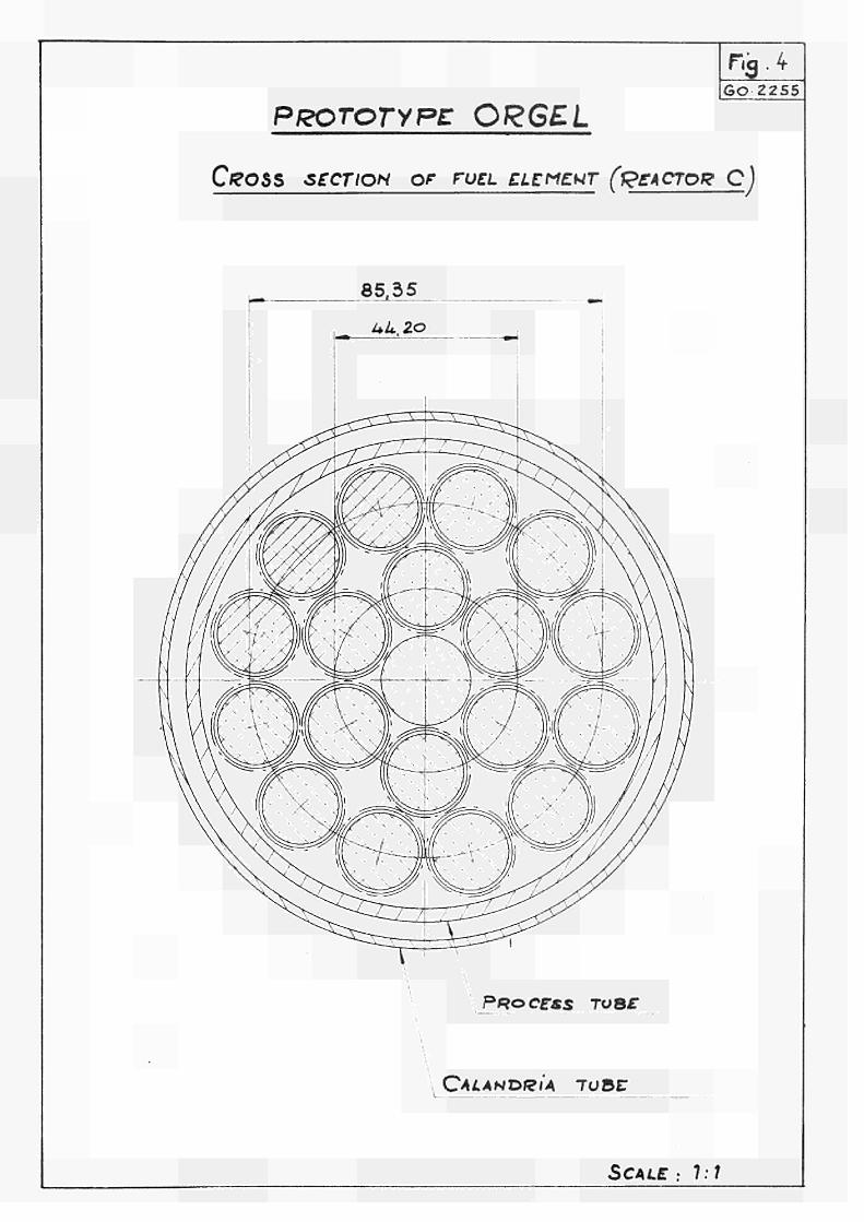
In all cases A, B, C an l8 rod bundle has been chosen being technologically viable and adapted to the 3 plants from an economical point of view (see figure 4). Economic power generation and stability criteria determine the rod diameters for the three cases as well as the ratio of coolant to fuel. Assembly of 6 (case A) and 5 (case Β and C) bundles has been foreseen with the help of a hanger bar, taking the place of the 19th rod in the center of the bundles, so to provide a means to guide and align bundles in the channel, to simplify fuel handling and to discharge axial loads from fuel canning.
Even if the computations made - supported by some experiments -show that canning would withstand under axial load in the foreseen conditions, the low safety margin obtained suggests for th· prototype an individual support for each bundle, fixed to the hanger bar. The supports possess positioning surfaces to center the assembly in the channel. Lenght of bundles (80 cm) has been fixed as a limit to prevent inacceptable vibrations of single rods, on the light of present out-of-pile experiments.
21
Canning thickness has been fixed to account for pressure difference between coolant and rod plenum for virgin and irradiated fuel and considering also ovality of canning itself. Proportionality between thickness and diameter has been chosen (5% of diameter).
Finning ratio has been fixed such as to lead to acceptable values of coolant and canning temperature and to prevent considerable temperature differentials in the circumference of the rod which would introduce important thermal bowing or, if prevented, significant thermal stresses. Computations were performed with thermal codes THESEE I and II / Ref. 6 and 7 7·
22
Main c o o l a n t a s s e m b l i e s (Coo l ing c h a n n e l )
The c o o l i n g c h a n n e l c o n t a i n s t h e f u e l e l e m e n t s and t h e
o r g a n i c c o o l a n t and s e p a r a t e s them from t h e m o d e r a t o r .
I t c o n s i s t s of t h e p r o c e s s t u b e , t h e i n s u l a t i o n gas and
t h e c a l a n d r i a t u b e .
The i n - c o r e p a r t of t h e p r o c e s s t u b e i s of SAP w i t h 10% Al 0 . S t e e l e x t e n s i o n t u b e s a r e a t t a c h e d t o each end 2 3 of t h e SAP t u b e by means of c o l d - r o l l e d j o i n t s . The
c o o l a n t e n t e r s t h r o u g h p i g t a i l s a t t h e upper p a r t of t h e
c h a n n e l and e x i t s a t t h e bot tom of t h e c h a n n e l . The t o p
of t h e c h a n n e l c o n t a i n s a s e a l i n g p l u g , which i s removable
f o r t h e on-power r e f u e l i n g 0 The lower e x t e n s i o n tube i s
p r o v i d e d w i t h a b e l l o w , a l l o w i n g f o r t h e t h e r m a l e x p e n s i o n
of t h e p r o c e s s t u b e .
The i n s u l a t i o n gas is s l o w l y c i r c u l a t i n g C 0 2 , which i s p r e s
s u r i z e d t o about t h e c o o l a n t o u t l e t p r e s s u r e , i n o r d e r t o
r e d u c e t h e p r e s s u r e d i f f e r e n c e a c t i n g on t h e SAP tube» The
c a l a n d r i a t u b e i s of Z r - 2 0
The SAP t u b e t h i c k n e s s has been c a l c u l a t e d w i t h t h e d e s i g n s t r e s s e s as s p e c i f i e d i n c h a p t e r 3 of document 2 i n t h e p r o t o t y p e t e n d e r l e d g e r s .
For t h e p l a n t C, hav ing t h e b i g g e s t c h a n n e l s and t h e l e a s t l a t t i c e p i t c h , t h e space between a d j a c e n t c h a n n e l e x t e n s i o n s i s r a t h e r smal lo So i t i s no t p o s s i b l e t o d i s p o s e f e e d e r t u b e s of s u f f i c i e n t d i a m e t e r t o c o n t a i n t h e e n t i r e c o o l i n g f low of a channe lo Each c h a n n e l i s t h e r e f o r e p r o v i d e d w i t h two i n l e t f e e d e r s and two o u t l e t f e e d e r s . For t h e p l a n t s A and Β t h i s i s n o t n e c e s s a r y .
23
IIo 3 · Neutron p h y s i c s
I n t r o d u c t i o n
The neutron p h y s i c s c a l c u l a t i o n s have been e v a l u a t e d by the codes : PLUTHARCO, CAPRI and RLT-2 /~Refo 8 7 deve loped by Euratom and EQUlPOlSE-3 /"Ref . 9_7» GAM-I /"Ref . 10_7 and WDSN /~Ref . 11 7 deve loped by o t h e r s ·
The PLUTHARCO code has been t e s t e d a g a i n s t v a r i o u s exper iments at I s p r a / Re f o 12 7<> Experiments w i th hot l a t t i c e s w i l l be performed i n the beginning o f 1969·
The RLT-2 code has been t e s t e d a g a i n s t Canadian exper iments / Ref. 13 7° O s c i l l a t i o n measurements with f u e l o f v a r i o u s i s o t o p i e c o n c e n t r a t i o n s o f uranium and plutonium i n order t o s i m u l a t e burn-up s t a t e s are being executed a c t u a l l y i n the ECO c r i t i c a l f a c i l i t y ·
A l l the r e s u l t s r e p o r t e d dea l wi th p o s s i b l e e q u i l i b r i u m c o r e s having two zones o f v a r i o u s burn-up i n order t o f l a t t e n the i n n e r core r e g i o n . The f u e l c y c l e always a p p l i e d was of b i d i r e c t i o n a l type o
R e a c t i v i t y ba lance
The c l e a n , hot c e l l parameters o f t h e i n f i n i t e l a t t i c e have been C a l c u l a t e d by means o f t h e code "PLUTHARCO".
As i n p u t data f o r the p h y s i c a l t emperatures of the c e l l mater i a l s the f o l l o w i n g v a l u e s have been adopted for a l l t h r e e r e a c t o r s } f u e l 660°C, coo lant 330°C, moderator 65°C. These v a l u e s were c a l c u l a t e d as core averaged v a l u e s for the r e a c t o r A. The thermal f l u x d i s t r i b u t i o n i n the f u e l c l u s t e r has been o b t a i n e d by means o f t h e code CAPRlo
24
The reactivity of the reactor zones is evaluated on the basis of the modified one group theory with aid of the zonal buck-lings calculated by the dimensioning procedure. The reactivity which can be reserved for the fuel burn-up has been obtained after having made reactivity reservations for the xenon poisoning effect, for control purposes and for reactivity losses by jointso
Fue l b u r n - u p
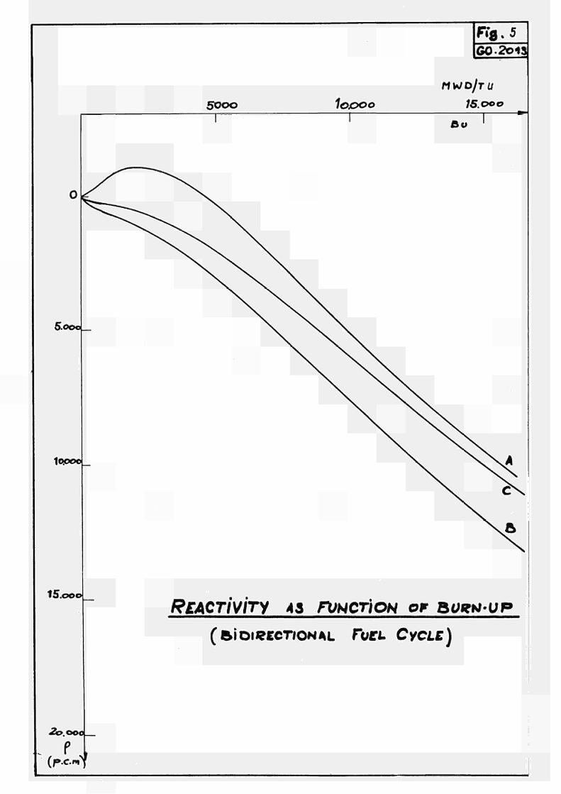
The f u e l b u r n - u p i s c a l c u l a t e d by t h e code RLT-2 which i s based on t h e mod i f i ed one group modelo I t c a l c u l a t e s t h e c o n c e n t r a t i o n s of t h e f u e l and f i s s i o n p r o d u c t s d u r i n g f u e l b u r n - u p i n a o n e - p o i n t model . The r e a c t i v i t y e v o l u t i o n of t h e f i n i t e r e a c t o r i s e v a l u a t e d by means of a p e r t u r b a t i o n methodo In i t s fue l management p a r t t h e code d e a l s w i th t h e c o n t i n u o u s b i d i r e c t i o n a l f u e l l i n g .
The r e a c t i v i t y e v o l u t i o n s of t h e t h r e e r e a c t o r s a r e shown
i n f ig« 5 .
E q u i l i b r i u m c o r e
The fue l of t h e e q u i l i b r i u m c o r e has been c o n s i d e r e d t o have
t h e i s o t o p i e c o n c e n t r a t i o n s a c c o r d i n g t o t h e mean b u r n - u p
of t h e zoneso
25
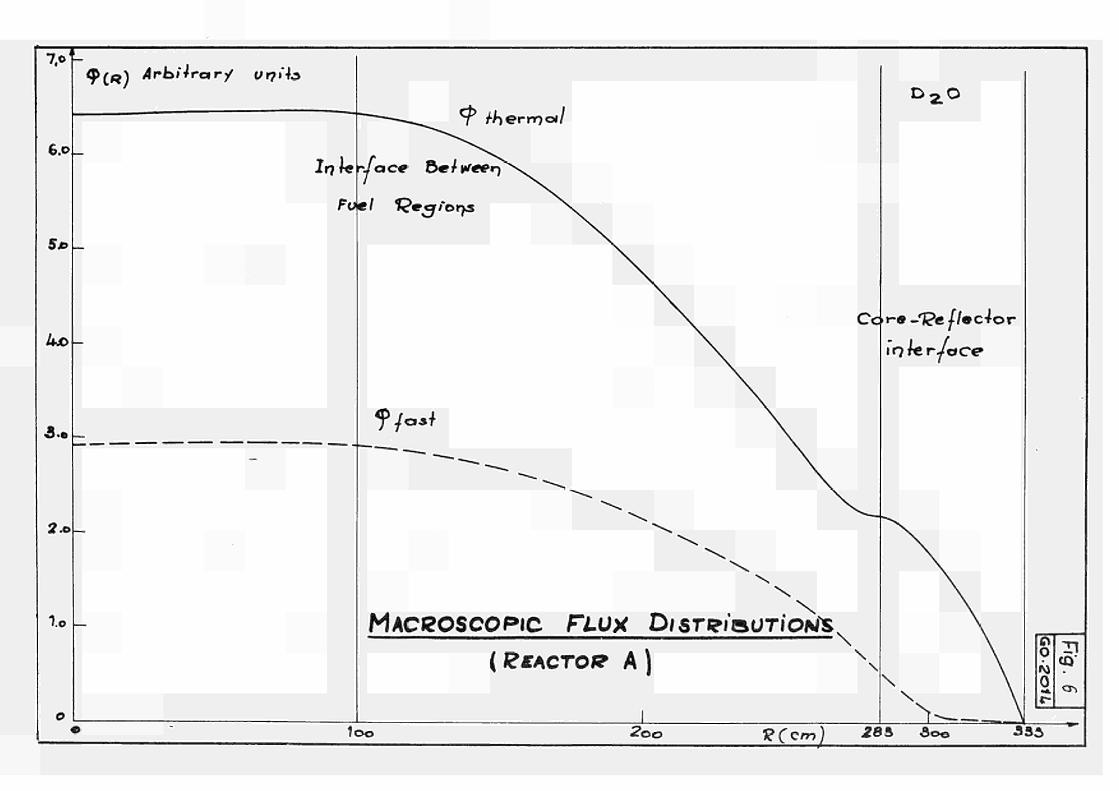
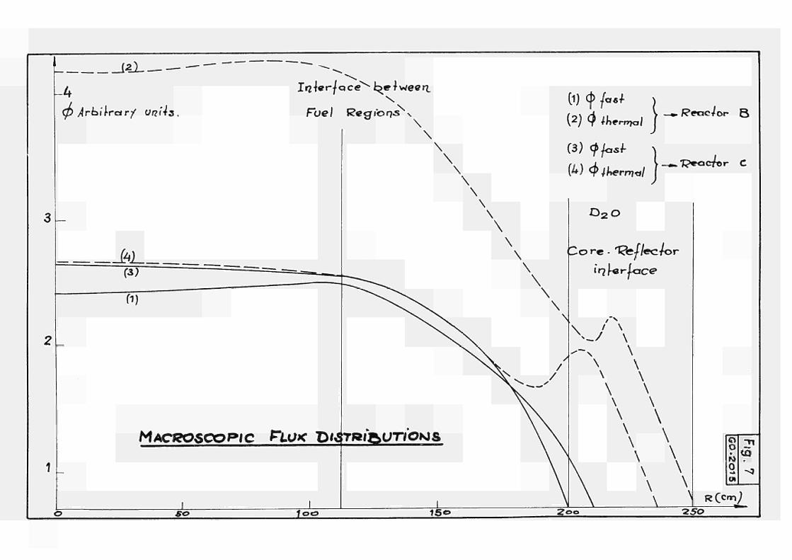
In the figures 6 and 7 are given the macroscopic radial flux distributions of the equilibrium cores. They have been calculated with EQUIP0ISE-3, a two dimensional two groups diffusion code.
The reactor assembly has been considered in the calculations as consisting of four regions of constant group parameters : the two homogenized core regions of various mean burn-up and the radial and axial reflector regions.
The cell parameters have been provided by PLUTHARCO fed with the equilibrium fuel compositions.
The mean temperature coefficients of the 3 reactor cores have been evaluated as follows : cell parameters for various temperatures of fuel, coolant and moderator are calculated by PLUTHARCO and then inserted into EQUlPOlSE-3 for a reactivity search. The difference in reactivity against the reference core defines the temperature dependence 0f th e cores. For evaluating independently the various temperature coefficients the fuel temperatures have been changed by - 100°C, the coolant temperature by - 50°C and the moderator temperature by - 15°C.
The void coefficient calculations have been performed in a similar way : lattice parameters are calculated for a voided cell by PLUTHARCO and are then introduced in the diffusion codeo It must be noted that PLUTHARCO is not adapted to treat unisotropic lattices. But as the coolant volume is in general relatively small in comparison with the cell volume the streaming effects will not influence very much the results.
- 26
An extrapolation of the reactivity coefficients given here for the equilibrium core to a possible fresh core has shown the following in earlier studies : the fuel coefficients become more negative, the other positive coefficients of coolant and moderator become negative or nearly zero; the void coefficients increase·
Concerning the void coefficient buckling measurements performed with voided natural uranium elements have been compared with PLUTHARCO calculations o The results show that this code underestimates always the voiding effect, especially for lattices of low moderating ratio. The values quoted in the tables of chapter 1.5 have been corrected accordingly for this effect.
Energy release in the core by neutron and gamma radiation
The kinetic neutron energy per fission is set equal to 4,8 MeV. After correcting for the neutron leakage the kinetic energy of the neutrons is considered to be released by elastic and inelastic scattering according to the reaction rates in the various core materials. The necessary cross sections have been calculated by means of the GAM-1 code for the homogenized coreo The spatial flux distributions (disadvantage factors) have been provided by a WDSN calculation.
The gamma ray spectrum has been calculated for 8 energy groups· After having corrected for the gamma ray leakage the energy has been distributed to the various core materials according to their attenuation coefficients assuming the reactor to be a homogeneous one. The homogeneous absorption yields are then corrected by selfshielding factors. These are obtained assuming the same subdivision in two regions as for the neutron energy absorption and considering the homogeneous channel zone as a uniform source of gamma rays·
- 27
II.4o Thermohydraulic performances
Primary coolant system
The organic coolant circulates from top to bottom of the reactor through the main coolant assemblies (coolant channels) in a single pass. The upper and lower extension of each channel is connected by individual pipes to a torical header situated above and below the core, serving at the same time as collector and mixing tanko The manifolds of all channels situated in a 90° section of the core are grouped together.
Four main coolant loops (in carbon steel) connect the headers with the four external steam circuits penetrating the biological shielding of the reactor block. Each loop is fitted with two motor-operated isolating valves in each duct (inside and outside the reactor containment)o The steam generator (drum boiler type) and one main coolant pump in the cold leg complete the coolant loop»
The steam circuits are connected to the torical headers such as to assure a uniform cooling of the core also in case of a pump failure in one main coolant circuit. All organic piping is fitted with steam trace heatingo
The maximum coolant velocity inside the coolant channels is fixed at 10 m/s; by appropriate orificing an equal heating of the coolant in all channels is assured. The primary coolant system pressure is chosen sufficiently high as to prevent local boiling in the peripheric channels.
28
Modera to r c o o l a n t sys tem _ - - _ — _ _ _ - - _ _ - — _ (
The f i s s i o n e n e r g y r e l e a s e d i n t h e m o d e r a t o r and t h e r m a l
l o s s e s from t h e c h a n n e l s a r e e v a c u a t e d by t h e m o d e r a t o r c o o l a n t
sys tem c o n s i s t i n g of t h r e e l o o p s , c o m p l e t e l y i n s t a i n l e s s
s t e e l , t h e main pumps a r e of t h e canned r o t o r t y p e . The l o o p s
a r e d i r e c t l y c o o l e d by raw w a t e r .
The h e a t i n g of t h e heavy w a t e r i n s i d e t h e r e a c t o r v e s s e l i s chosen r e l a t i v e l y h i g h (30°) i n o r d e r t o d e c r e a s e t h e volume of D O i n t h e l oops and t o r e d u c e t h e i n v e s t m e n t s . The m o d e r a t o r i n t h e r e a c t o r v e s s e l i s s l i g h t l y p r e s s u r i z e d (abou t 1.5 a t a ) t o p r e v e n t any l o c a l b o i l i n g of t h e m o d e r a t o r . D O flow i n t h e c a l a n d r i a v e s s e l i s upwards .
The m o d e r a t o r a u x i l i a r y s y s t e m s a r e composed of a double D O
p u r i f i c a t i o n sys tem by i o n - e x c h a n g e , a c a t a l y t i c r e c o m b i n a t i o n
sys tem and a he l ium p u r i f i c a t i o n s y s t e m . Al l p a r t s of t h e s e
sys t ems b e i n g i n c o n t a c t w i t h D O a r e made of s t a i n l e s s s t e e l .
F u e l p e r f o r m a n c e s
The maximum l i n e a r h e a t r a t i n g of t h e f u e l r o d s has been
s e l e c t e d a c c o r d i n g t o t h e r e q u i r e m e n t s of t h e e n v i s a g e d r e a c t o r
s t r i n g ( s e e a l s o P a r t D o
For t h e n a t u r a l uranium r e a c t o r s t r i n g ( t y p e A) w i t h i t ' s
r e s t r i c t e d n e u t r o n b a l a n c e i t was n e c e s s a r y t o f i n d a compromise
between an a c c e p t a b l e s p e c i f i c power of t h e f u e l and a s m a l l
r a t i o of c o o l a n t t o f u e l s e c t i o n .
29
The high performance string (type B ) , taking full advantage of the good thermal conductivity of the uranium carbide fuel, works witli a high maximum linear heat rating. Conserving the same fuel rod diameter as for the string A the specific power of the fuel is more than doubled, thus minimizing fuel and heavy water inventory in the core and maximizing the burn-up by a slight enrichment«
The high performance string of intrinsic stability (type C) with it's large fuel section (and greater fuel rod diameter, as the basic option of a G-l8 type element is conserved) holds a medium position between string A and B; the specific power of the fuel is about 30% higher than for A and the maximum linear heat rating exactly twice that of A. Consequently, the specific investments in fuel and heavy water are rather close to those of the Β type stringo
For all three strings the maximum allowable temperature of the SAP cladding of the fuel rods is fixed at 425°C (without accounting for hot spots). Assuming a mean contact resistance
-1 of 1°C cm W between fuel and cladding the maximum fuel rod central temperatures do not exceed 1»200 0 C
Ilo5· Steam cycle
The steam cycle adopted is a classical one with superheat and reheat by the primary coolant and feedwater heating by extraction steam. The thermodynamic efficiency of such steam cycles has been evaluated under EURATOM contract, in a range of primary coolant temperatures and steam pressures being typical for an ORGEL power plant.
30
A four loop design is chosen with superheater and reheater arranged in series. The steam generator is of the drum boiler type0
The heat exchanger surface was calculated by the EURATOM 1) internally developped code HDP - 1 . A s this code does
not foresee steam reheating the surface was calculated for a steam cycle without reheat, but having the same steam pressure and pinch points at the evaporator inlet and superheater outlet as the reheat cycle. Moreover, this code does not take into account any pressure drop inside the steam generator, so the surface calculation was done with the turbine inlet pressure. The reheater surface was estimated to be equal to that of the superheater«
II060 Organic coolant and coolant purification syst em
The organic coolant is a mixture of ortho-, meta-, and parater-phenyls (commercially known as OM-2) containing 5% high boiling residues (HB). The physical properties of this coolant and the reasons for it's choice are described in / Ref. 15 7°
In order to eliminate the decomposition products produced in the organic coolant under the influence of radiation and temperature in the reactor a purification system is provided based on the distillation processo A certain quantity of coolant is bypassed from the main coolant loops and continuously sent through the purification system, thus keeping the HB-content at the preset level.
(l) Not available; an improved version HDP-2 is to be published soon /"Ref. 14 7·
- 31 -
The total organic coolant decomposition rate takes into account the combined effects of radiolysis and radiopyrolysis. The first can be split up to into fast neutron degradation and gamma ray degradation. The ratio of G to Gir has
neutron ν been assumed to 4 according to recent results obtained at the CEN Grenoble. The fast neutrons account for the greatest fraction of total decomposition rate (85%), the gamma rays contribute about 12% and the rest is due to radiopyrolysis. The radiolytic degradation is supposed to follow a second order law, for the radiopyrolysis a first order law is assumed. The radiopyrolysis degradation constant is strongly temperature dependent; so, at the relatively law level of organic coolant outlet temperature (360°C) the radiopyrolysis is of little importance. Only the organic coolant being at reactor outlet temperature is assumed to participate in radiopyrolysis.
II.7· Reactor stability
Method /"Ref. 16 7
An analytic study has been developped from the set of differential equations describing the kinetics and heat transfer of the reactor. This method, unlike a numerical calculation as the normally used analogue computation, presents the great advantage to give the physical laws of the different parameters for stability which is very useful when the matter is to compare the stability of several reactor types.
32 -
The mathematical tool is the servo-theory which assumes that
the studied physical systems are described by sets of linear
differential equations with constant coefficients : it is not
the case for the kinetic equations and the method is valid
only for small variations around a specific steady state.
The physical effects of the temperature coefficients have
been translated in servo-loop feedback which modifies the
elementary reactor transfer functions; account has been
taken of the axial (for a cosine flux) and radial statistical
weight of the temperatures. The steady state operation
program of the reactor is one with a constant coolant flow and a
constant coolant inlet temperature.
Results
Stability condition
The stability condition is defined by
Λ C
'̂ U
fi Τ - Τ r. , Η O U C
where : 1 = 1 + — „ s 3 ûT
ö̂ = coolant temperature coefficient
(χ = fuel temperature coefficient
Τ = average fuel temperature in the channel of medium
power
Τ = average coolant temperature in the channel of
medium power
AT = coolant temperature span

33 -
Reactor string
I w/ cm
pcm/°C
pcm/°c
1 s
<*u
Stabilitv
A
40
- 0,4
+ 5,2
4,3
13
Unstable
Β
90
- 0,3
+ 5,0
7,8
17
Unst able
c
bO
- 1,1
+ 1,8
7,3
1,6
Stable
Power coefficient
It is defined by the following equation
°c= io~2 4 ^ <* +<* ι ) w 2 c u s
(pcm/% power)
Reactor String
OCw (pcm/%)
A
+ i»3
Β
+ 1,0
c - 2,2
As an illustration (Fig. 8 and 9) are reported in the ( Ot , 0< ) plane the stability regions and the lines correspon-c u ding to variable power coefficients for the reactors Β and Co These plots give an idea of the gain of stability when the uncertainty on the values of the temperature coefficients is taken into account o
34
IloBo Economy of the plants
Direct _costs of construction
The direct investment for the 3 plants was calculated by adjusting the results of the 250 MWe Reference Design Study Contract carried out between January 1962 and 1963 by the firms Belgo-Nucléaire/Indatom/Siemens / Ref. 17„/· The cost estimates established under this contract were based on the state of technological development in 19b2 and had the aim of ascertaining the fixed charges for both a 250 MWe gross ORGEL prototype and an already industrially-mature ORGEL power plant of 250 MWe gross (tete de filiere). The estimates given hereunder refer to the ORGEL plant "tete de filière".
In order to escalate these I962 cost figures to 1966 figures, a rate of 2.4 > per year was assumed, totalling at 10% escalation in 4 years o
The direct construction costs include the reactor, it's primary circuits, steam generators, moderator and coolant, but not the first charge of fuel and the fuel reserve. In addition, they include site clearance, civil engineering work, auxiliary work, turbogenerator unit, electrical equipment and main step-up transformers, but not the land. Heavy water is estimated at 20 $/lb.
Indirect costs of construction
The indirect xosts include engineering, overheads and administrative costs, interest during construction, possible price
1) increases till putting m operation and contingencies
(l) Taxes on capital and return on capital during construction are not included in view of the fact that their incidence, which depends on the tax system applicable in the country where construction takes place, may vary between O and 6% in the Community. No account is taken of customs duties, it being assumed that all equipment is supplied from within the Community.
35 -
The percentage of indirect costs (35%) is based on the results of the Symposium on Technical and Economical Problems for Proven-Type Reactors held in Venice in October 1963·
Fixed costs of plant investment
The fixed costs due to plant investment (annual instalment) include interest on money, amortization and taxes on revenues. The total annual instalment variefi considerably in the countries of the European Community, between 8ol% (France), 10% (Italy, The Netherlands), and 13% (Belgium, Germany)·
Interest rates are in general between 5.5 and 7%« Amortization rates are based on estimated lifetime between 20 and 30 years for proven reactor types; in Germany and The Netherlands plant lifetime is shorter for fiscal reasons. Thus the amortization rates .in the community are related to plant lifetimes between 15 and 30 years. Taxes on revenues are also quite different ranging from exemption (France, The Netherlands) to 3% - 4% per year on the revenues (Belgium, Germany).
In this economical evaluation a medium value of 10% is chosen for annual instalment. The annual plant load factor is taken as 0.8 equal to 7OOO h of full load operation per year.
Fuel circle costs
Fuel cost
The cost of the raw materials is taken as 8 $/lb U_0o for the 3 o
n a t u r a l uranium f u e l ; for the e n r i c h e d f u e l c o s t i s 6 l $/kg U as UF6 f o l l o w i n g the USAEC p r i c e l i s t from July 1962„(θί= 1,14 %)
The c o s t s o f c o n v e r t i n g U„0o or UF, i n t o UC are assumed t o 38 3 0 o
and 40 $/kg U r e s p e c t i v e l y for the n a t u r a l and the enr iched f u e l .
36 -
Cost of SAP sheaths differ somewhat between the natural uranium fuel without fins (3 $/kg U) and the enriched fuel with finned sheaths (5 $/kg U).
The cost of cladding, assembly and inspection is taken at 13 $/kg U (natural uranium fuel) and 14 $/kg U respectively (enriched fuel)o
Total costs of fuel elements 1)
enrichment (vit.% U-235) costs ( S/kg U )
0,71 75
0,93 100
1,14 120
1,35 140
Fuel_cycle_costs (equilibrium core)
In calculating the fixed costs of the equilibrium fuel cycle the half first-charge costs were amortized over the whole plant lifetimeo The interest rate on spare fuel (equal to 10% of the fuel charge) is 6%. Annual instalment rate and plant load factor are the same as for the fixed costs of plant investments.
The variable costs of the fuel cycle (fuel consumption) have been calculated firstly without Pu-recovery from spent fuel, secondly with Pu-recovery. In the latter case, only the extracted Pu-isotopes are accounted as a credit (at 8 $/g Pu), the residual U-235 of the enriched fuel is not considered. Reprocessing and transportation costs are taken at 21 $/kg U.
Operation and maintenance costs
The costs include only organic make-up costs and D 0-losses. All other operation, maintenance and insurance costs are omitted because of their dependance on local conditions and the operation strategy of the plant owner.
1) The slight variation of fuel '-osts with fuel rod diameter has been neglected. Consideration of this effect would give reactor C a small advantage in cost over reactor B.
37 -
O r g a n i c c o o l a n t make-up c o s t s a r e c a l c u l a t e d f o r an
e q u i l i b r i u m c o n t e n t o f 5% HB t o be mainta ined by d i s t i l l a t i o n . Cost of f r e s h c o o l a n t i s O.3O $ /kg 0
Compar i sons of D O l o s s e s fo r o p e r a t i n g heavy w a t e r mode-¿à
r a t e d and c o o l e d r e a c t o r s gave f i g u r e s between 0 . 2 and 9% p e r y e a r of t o t a l D O i n v e n t o r y .
For a l l t h e s e f i g u r e s i t i s s t r e s s e d ou t t h a t t h e l o s s e s
o c c u r e d ma in ly d u r i n g t h e p e r i o d s of p r e s s u r i s e d p r i m a r y
D O c i r c u i t .
For an ORGEL t y p e r e a c t o r b e i n g o n l y modera ted by D O
w i t h o u t h igh o p e r a t i n g p r e s s u r e s one can r e a s o n a b l y assume
y e a r l y D O l o s s e s a t about 0,5% of t o t a l i n v e n t o r y .
- 38 -
I I I . Refe r e n c e s
/ 1 7 Seven rod uranium c a r b i d e ( U C / 7 / 3 0 . 9 ) b u c k l i n g measu
r e m e n t s and a n a l y s e s .
H. H e t t i n g e r , Ho Hohmann, W. I z z o , M. P a i l l o n
Euratom Communicat ion ( 1 9 6 8 ) , n o t a v a i l a b l e .
/ 2 7 PLUTHARCO, a p l u t o n i u m , u r an ium, t h o r i u m assembly
r e a c t i v i t y c o d e . P h y s i c a l c o n c e p t s , c o m p a r i s o n s w i t h
e x p e r i m e n t s and code d e s c r i p t i o n .
Wo de Haan, R. Meelhuysen
EUR-3141 e (1967)
/ ~ 3 7 A s t u d y of t h e p l u t o n i u m r e c y c l e i n a 250 MWe ORGEL
r e a c t o r .
G. G r a z i a n i , M. P a r u c c i n i , C. R i n a l d i n i , C. Z a n a n t o n i
Euratom Communicat ion ( 1 9 6 8 ) , n o t a v a i l a b l e .
/ " 4 7 Code ORION-II
Code d ' o p t i m i s a t i o n d ' u n r é a c t e u r ORGEL a s s o c i é à une c e n t r a l e p r o d u c t r i c e d ' é l e c t r i c i t é . W. B o e t t c h e r , B. H a y t i n k , F . L a f o n t a i n e , P . Tauch EUR- 4067 (1968)
/ ~ 5 7 CAPRI.A.B. An IBM 7090 t h e r m a l u t i l i s a t i o n f a c t o r c a l
c u l a t i o n program on t h e r i n g method of Amouya l -Beno i s t
W. de Haan
EUR-I606 e (1964)
/ 6 7 THESEE-1. Code de c a l c u l des p e r f o r m a n c e s d ' u n c a n a l
de r é a c t e u r du t y p e ORGEL.
B. Chambaud, P . C i v a r d i , G. Di C o l a , R. Di C o l a .
EUR-3905 f (1968)
- 39 -
/ 7 7 THESEEII : Code de c a l c u l d e s p e r f o r m a n c e s h y p e r f i n e s
d ' u n c a n a l de r é a c t e u r du t y p e ORGEL.
B. Chambaud, P . C i v a r d i .
EUR (1968) t o be p u b l i s h e d
/ 8 7 V a r i a t i o n de l a r é a c t i v i t é à long te rme pour d i f f é r e n t s
t y p e s de c i r c u l a t i o n du c o m b u s t i b l e o
G. B l a e s s e r , G. C a s i n i , J . P i i l o n
EUR129 f (1962)
/ 9 7 EQUIPOlSE3 : A t w o d i m e n s i o n a l , t w o g r o u p , n e u t r o n
d i f f u s i o n code f o r t h e IBM7090 Computer .
T . B . F o w l e r , MoL. T o b i a s
ORNL3199
/ 10 7 GAMI : A c o n s i s t e n t Ρ m u l t i g r o u p code f o r t h e c a l c u
l a t i o n of f a s t n e u t r o n s p e c t r a and m u l t i g r o u p c o n s t a n t s .
G.D. J e a n o n , J . S . Dudek
Ga1850 (1961)
/ " l l 7 The W i n f r i t h DSN program
S. F r a n c e s c o n
AEEWR 273 (1963)
/ 12 7 Heavy w a t e r l a t t i c e a n a l y s e s a t I s p r a
L. Amyot and a l .
P r o c . on t h e Conf. P h y s i c s P rob lems i n Thermal R e a c t o r
Des ign June I 9 6 7 .
/ 13 7 A s i m p l i f i e d method f o r o r g a n i c , heavy w a t e r l a t t i c e
c a l c u l a t i o n s .
G. C a s i n i , A. Kind, G. R o s s i .
EUR238 e (1963)

40 -
/""l4 7 HDP-2 : A digital program calculating the surfaces and the efficiencies of a heat exchanger coupled with a turbine at nominal power and part load. W. Balz, C. Bona EUR- (1968) to be published.
/ 15 7 Le réfrigérant organique dans le cadre du Programme ORGEL de 1'EURATOM. J.C. Leny EUR-2996 f (1966).
/~16 7 ORGEL Dynamics. W. Balz, C. Bona, A. Decressin, H. D'Hoop, J. Noailly EUR- (1968) , to be published.
/~17 7 ORGEL Reference Design - Contract 046-62-1 ORG.C EUR-1616 e (I967).
Acknowledgements: The authors wish to thank Messrs. Balz, Cadelli, Chambaud, Haijtink, Huber, Rinaldini and Terrien for their contribution to this report.
7 8 9 10*
4 500 6 7 8 9-tøJØ 3 4 Ä0Ö0 6 7 8 9'fttøOØ 4 SutfOOG 7 :áfc. '
ι n n . r Teilung L o g a r
· Division i-i« S^-1}»-«- Ed. Aerni-Leuch, Bern. Nr 534
mills kwh
6.5
Total energy production costs
without Pu-recovery·
Fig. 1 GO - 1977
5,5
r =iov. h =7000 h/y
-o—
' Q —
S5 A Β C
1.0 1.3 1.6 1.9 Y relative enrichment in U-235
Fig. 2
GO-1978 Total energy production costs
with Pu.recovery-
mills kwh
Γ =10 V. h =7000 h /y
5,5
· ·—
4,5-Β
C
1,0 1,3 1,6 1,9 Y relative enrichment in U-235
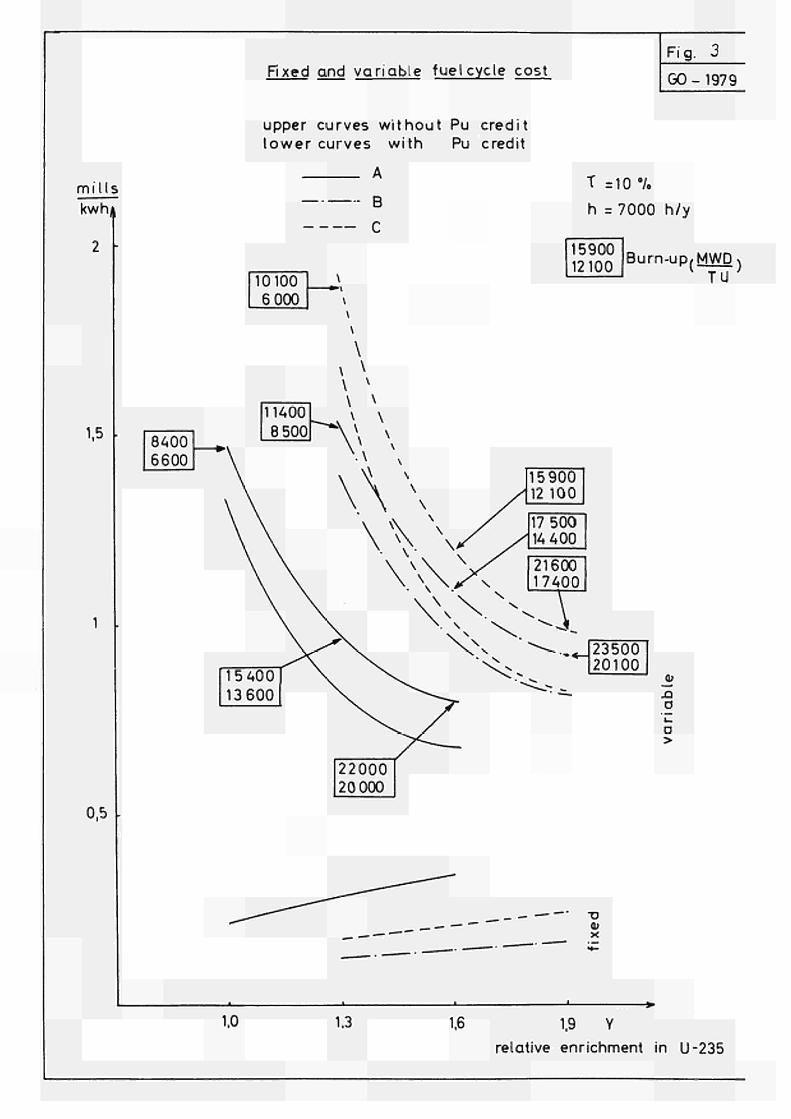
Fixed and variable fuel cycle cost Fi g. 3
GO - 1979
mi Us
kwhå
1,5
0,5 -
upper curves wi thout Pu credit lower curves wi th Pu credit
A
Β
C
Τ =10 '/.
h =7000 h/y
15900 12100
Burn-uP/MWD) TU
0)
σ
o >
_ _ _ - — — XI ω χ
1.0 1,3 1.6 1.9 Υ
relative enrichment in U-235
ria Λ GO 2255
PROTOTYPE ORGBL
C/?OSS 3£CTlON OF FUEL CLEMZUT (l?£'ACTOR C )
85,35
PROCESS TUBE
V C A L A N D R I A T U B E
SCALE : hi
5 0 0 0 IOJOOO
F¡B%5 G02O13
«WD/T í / 75. œ ©
Ou
5.0OC
1C!POO
15.000 REACTIVITY 43 FONCTION o* BORTUR
(ÄioueccTiONAL Fort. Cyczx)
2b.oo<
V Φ C*?) Arhìlrar·/ urjiía
6.0
5x>
UJO
3.1
2.0
»-•-1?e^/*c4or
■Ό /β r^ci c e
MACROSCOPIC Ftux D/sr^i'sun'ow* ( J?éTACTOJ? A )
1o© 2ao •RÇcrn)
O ^ O
¿85 3oo 3 3 3
: tu —
φ Arkí/-rear/ unMs Fuel ReøTor?^
faL f3>
Π)
M A C g Q 5 C Q P I C PUT* P^TRI&UTIOlsJS
■go lots
\
\
0) <}> ƒ««+
\ \
\ \
C3) <H**l· - » ■ p e o c / o r C
\
15«
\
\
\
\
\
\
0 2 0
Zore- 1<k/7eCror
"7 l·« rLace
\
\ \
\ \
\ \ \ \
\ \
V
o * M O (M
CO
RQtnri)
Z o o ^■5P
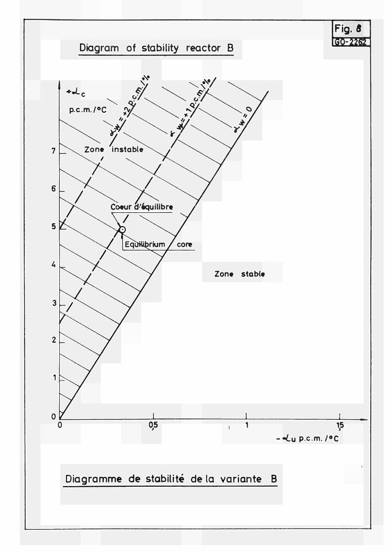
Diagram of stability reactor Β
Fig.*
ΙΦΜΦτΙ
--¿u p.c.m./*C
Diagramme de stabilité de la variante B
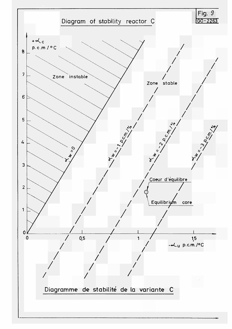
Diagram of stability reactor C Fig. 9 GO-2263
u p.c.m./°C
Diagramme de stabilité de la variante C
NOTICE TO THE READER
All Euratom reports are announced, as and when they are issued, in the monthly periodical EURATOM INFORMATION, edited by the Centre for Information and Documentation (CID). For subscription (1 year : US$ 15, £ 6.5) or free specimen copies please write to :
'i#S ? 'in«' ™I^ Handelsblatt GmbH "Euratom Information" Postfach 1102 D-4 Düsseldorf (Germany)
mm Mm
.t**i P»! Vii in ' : rnfttAiîl^ii!^
lii To disseminate knowledge is to disseminate prosperity — I mean III; general prosperity and not individual riches — and with prosperity
disappears the greater part of the evil which is our heritage darker times.
SALES OFFICES
iiaSiií'MiiB^Suiui1 riunir y given on the back of the ι of the report, which are
fiSSHMI
All Euratom reports are on sale at the offices listed below, at the prices front cover (when ordering, specify clearly the EUR number and the title shown on the front cover). ironi cover; .
ΐΡΐΙΙΙ^ΜΜηΡΗ CENTRALE DE VENTE DES PUBLICATIONS DES COMMUNAUTES EUROPEENNES 37, rue Glesener, Luxembourg (Compte chèque postal N° 19190)
BELGIQUE — BELGlI 1 0 4042, rue de Louvain Bruxelles BELGISCH STAATSBLAD Leuvenseweg 4042 Brussel 3'
DEUTSCHLAND
BUNDESANZEIGER Postfach Köln 1
11*1' FRANCE jtjjlwffl SERVICE DE VENTE EN FRANCE DES PUBLICATIONS DES COMMUNAUTES EUROPEENNES 26, rue Desaix Paris 15e
lili LUXEMBOURG
CENTRALE DE VENTE DES PUBLICATIONS DES COMMUNAUTES EUROPEENNES 37, rue Glesener Luxembourg
NEDERLAND STAATSDRUKKERIJ Cbristoffel Plantijnstraat Den Haag
ííiSfrÍr ¿www Çrlffll^PBiW
ÍSmmÊmÊÊmrA
m UNITED KINGDOM
H. M. STATIONERY OFFICE P. O. Box 569 London S.E.I
M
mm
M
CDNA04209EN(
ïIH rJii¡t: WHO* t,-mr'\¡-¿rr
Wmmm 1
E U R A T O M — C.I.D. 29, rue Aldringer L u χ e m b o ) u r g
'fil
ffîlhnlKk


![Crimp Information Sheet - Farnell element14 · 2018. 10. 3. · CCW [mm] Tol CCW [mm] ICH [mm] Tol ICH [mm] ICW [mm] Tol ICW [mm] 10070,50/15366060 2,15 80 1,10 0,05 1,80 0,10 3,50](https://static.fdocument.org/doc/165x107/6119fa6ed77d58264702c930/crimp-information-sheet-farnell-2018-10-3-ccw-mm-tol-ccw-mm-ich-mm.jpg)