& Microelectronics and Embedded Systems M 2 μP - Multithreading Microprocessor Thesis Presentation...
33
& Microelectro nics and Embedded Systems M 2 μP - Multithreading Microprocessor Thesis Presentation Embedded Systems Research Group Department of Industrial Electronics School of Engineering, University of Minho, Guimarães - Portugal Microelectronics and Embedded Systems Industrial Systems Engineering, Asian Institute of Technology, Pathum Thani - Thailand Filipe Salgado
-
Upload
agustin-holyfield -
Category
Documents
-
view
227 -
download
1
Transcript of & Microelectronics and Embedded Systems M 2 μP - Multithreading Microprocessor Thesis Presentation...

&Microelectronics and Embedded
Systems
M2μP - Multithreading Microprocessor
Thesis Presentation
Embedded Systems Research Group
Department of Industrial Electronics
School of Engineering,
University of Minho, Guimarães - Portugal
Microelectronics and Embedded Systems
Industrial Systems Engineering,
Asian Institute of Technology,
Pathum Thani - Thailand
Filipe Salgado
&Microelectronics and Embedded
Systems
Summary
1. Objectives of Study2. Processor’s characteristics3. Methodology4. Customizable features
1. Front-end2. Execution engine3. Caches
5. Conclusions6. Future perspectives
&Microelectronics and Embedded
Systems
1. Objectives of Study
• Horizontal design goals (long-term):
•Design a processor template suitable for integration on a Design Space Exploration (DSE) tool
•High level of customization to fit application’s specifications constraints (high-performance vs low power, etc)
&Microelectronics and Embedded
Systems
1. Objectives of Study
• Vertical design goals (short-term):
•Low power microprocessor
•Multi-thread processing
•Flexible Instruction Set Architecture (ISA)
•Easilly Customizable
&Microelectronics and Embedded
Systems
2. Processor’s characteristics
1. 16-bit RISC architecture
2. Three stage pipeline
3. Load/store architecture
4. Multi-threading execution
5. Eight general purpose registers
&Microelectronics and Embedded
Systems
2. Processor’s characteristics
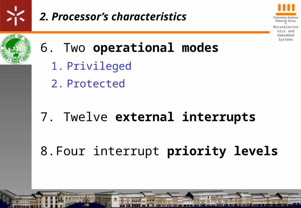
6. Two operational modes1. Privileged
2. Protected
7. Twelve external interrupts
8. Four interrupt priority levels
&Microelectronics and Embedded
Systems
2. Processor’s characteristics
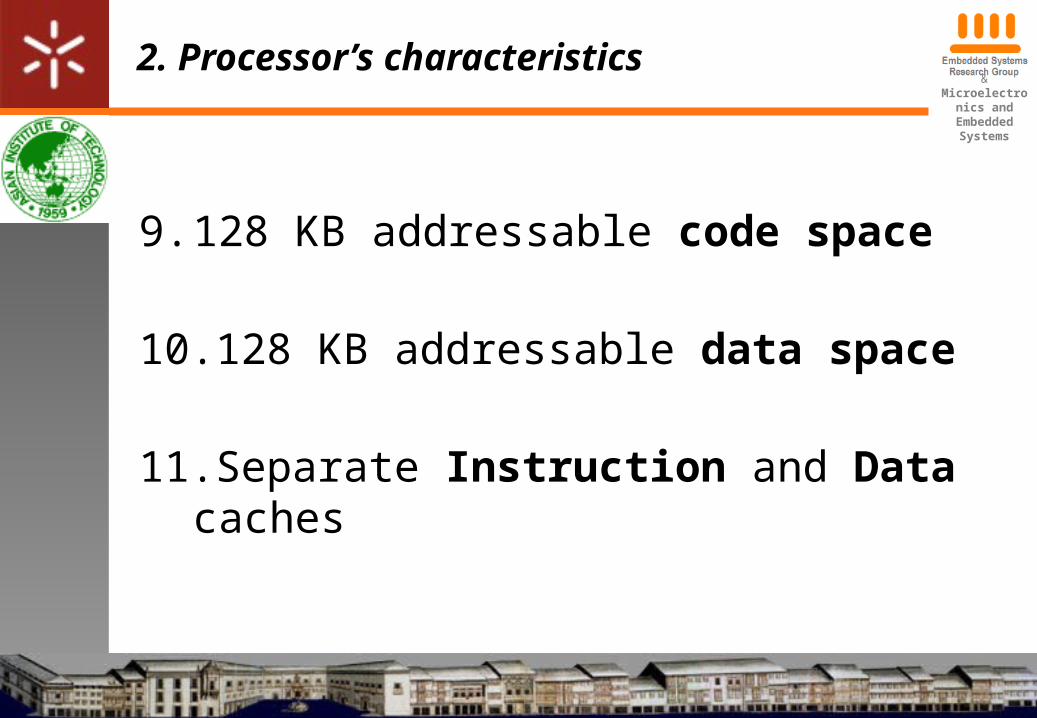
9. 128 KB addressable code space
10.128 KB addressable data space
11.Separate Instruction and Data caches
&Microelectronics and Embedded
Systems
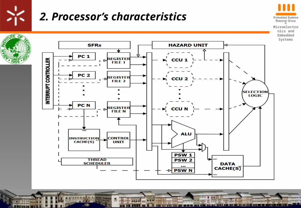
2. Processor’s characteristics
&Microelectronics and Embedded
Systems
3. Methodology
• This implementation requires a great design and implementation effort
• Workload divided in three parts
• Front-end, by Paulo Garcia• Execution engine, by Tiago Gomes• Memory hierarchy, by Filipe Salgado
&Microelectronics and Embedded
Systems
3. Methodology
• High customization level
• Making the processor proper to the specific purpose
• Allows savings in:• Area• Fabrication costs• Power consumption
&Microelectronics and Embedded
Systems
3. Methodology
• High customization level
• Front-end customizations
• Number of hardware supported threads
• Controllable thread scheduling policy
• Easy addition of new instructions
&Microelectronics and Embedded
Systems
3. Methodology
• High customization level
• Execution Engine customizations
• Reconfigurable ALU to target:
– Performance
– Low power consumption

&Microelectronics and Embedded
Systems
3. Methodology
• High customization level
• Execution Memory Hierarchy
• Easy Instruction and Data cache modification
– Three different organizational architectures
– Storage capacity

&Microelectronics and Embedded
Systems
4. Customizable features
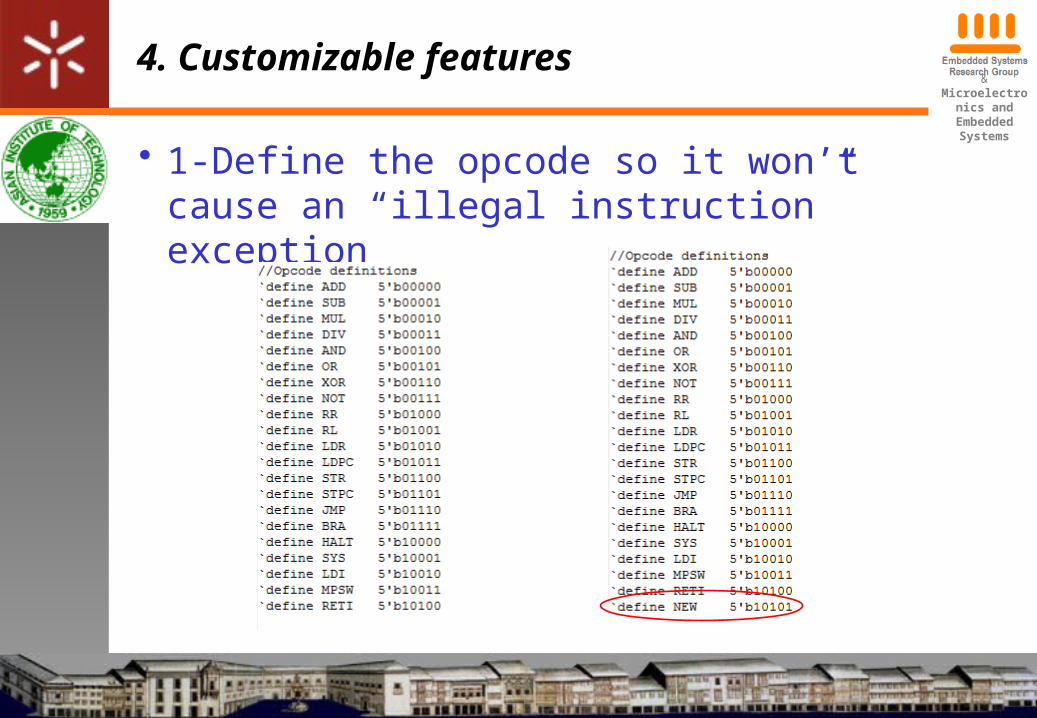
• Front-end customization•To add a new instruction the following steps must be performed:
• 1 - Define the opcode so it won’t cause an “illegal instruction” exception
• 2 - Define the operand format• 3 - Add control codes generation
&Microelectronics and Embedded
Systems
4. Customizable features
• 1-Define the opcode so it won’t cause an “illegal instruction” exception
&Microelectronics and Embedded
Systems
4. Customizable features
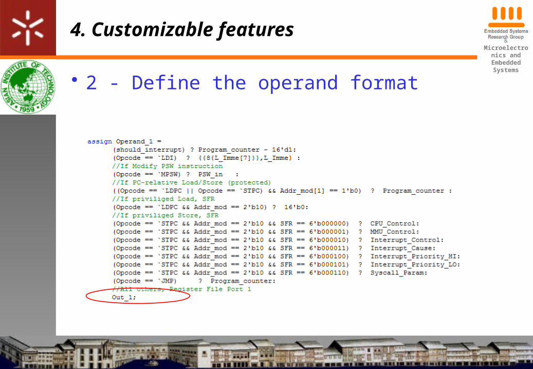
• 2 - Define the operand format
&Microelectronics and Embedded
Systems
4. Customizable features
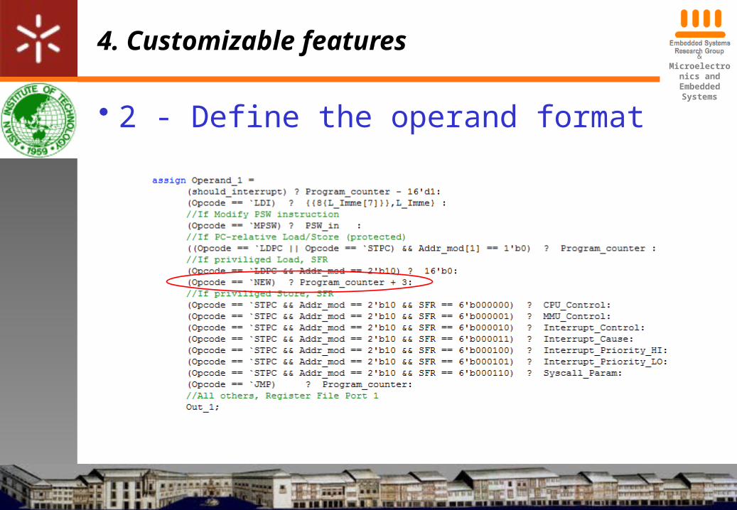
• 2 - Define the operand format
&Microelectronics and Embedded
Systems
4. Customizable features
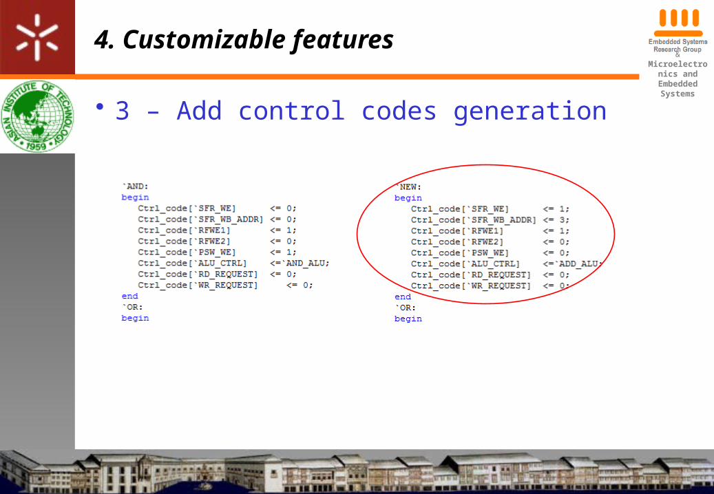
• 3 – Add control codes generation
&Microelectronics and Embedded
Systems
4. Customizable features
• ALU customization
•ALU can be modified to target performance or low power consumption
•Also further techniques can be applied to reduce power consumption
&Microelectronics and Embedded
Systems
4. Customizable features
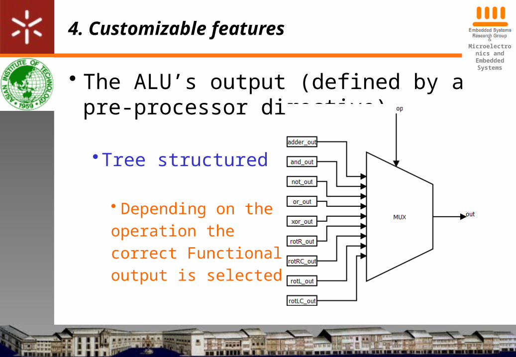
• The ALU’s output (defined by a pre-processor directive)
•Tree structured
• Depending on the operation thecorrect Functional Unit’soutput is selected
&Microelectronics and Embedded
Systems
4. Customizable features
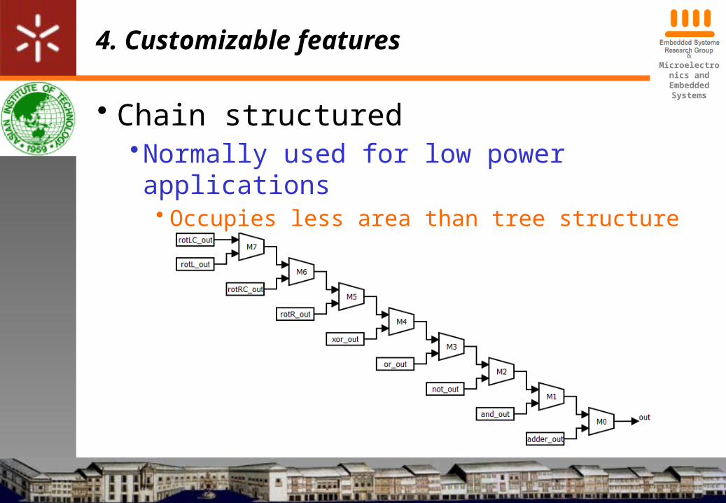
• Chain structured•Normally used for low power applications
• Occupies less area than tree structure

&Microelectronics and Embedded
Systems
4. Customizable features
• ALU power consumption reduction techniques
•Gating logic
• Gating all the input signals of each Functional Unit with transmission gates
• When a Functional Unit is not being used, its input will be in a High Z state

&Microelectronics and Embedded
Systems
4. Customizable features
• ALU power consumption reduction techniques•Repositioning functional units in the chain• Application profiling• Place the FUs most frequently used closest to the output
• Reducing the signal switching
&Microelectronics and Embedded
Systems
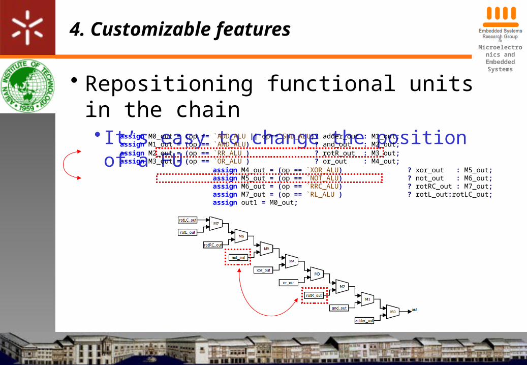
4. Customizable features
• Repositioning functional units in the chain• It’s easy to change the position of a FUassign M0_out = (op == `ADD_ALU || op==`SUB_ALU)? adder_out : M1_out;assign M1_out = (op == `AND_ALU) ? and_out : M2_out;assign M2_out = (op == `RR_ALU ) ? rotR_out : M3_out;assign M3_out = (op == `OR_ALU ) ? or_out : M4_out;
assign M4_out = (op == `XOR_ALU) ? xor_out : M5_out;assign M5_out = (op == `NOT_ALU) ? not_out : M6_out;assign M6_out = (op == `RRC_ALU) ? rotRC_out : M7_out;assign M7_out = (op == `RL_ALU ) ? rotL_out:rotLC_out;assign out1 = M0_out;
&Microelectronics and Embedded
Systems
4. Customizable features
• Caches customization
•5 different organizational models are available to fit the application specific requirements.• 2 Instruction cache models• 3 Data cache models
•The cache size of each model is defined during compile time
&Microelectronics and Embedded
Systems
4. Customizable features
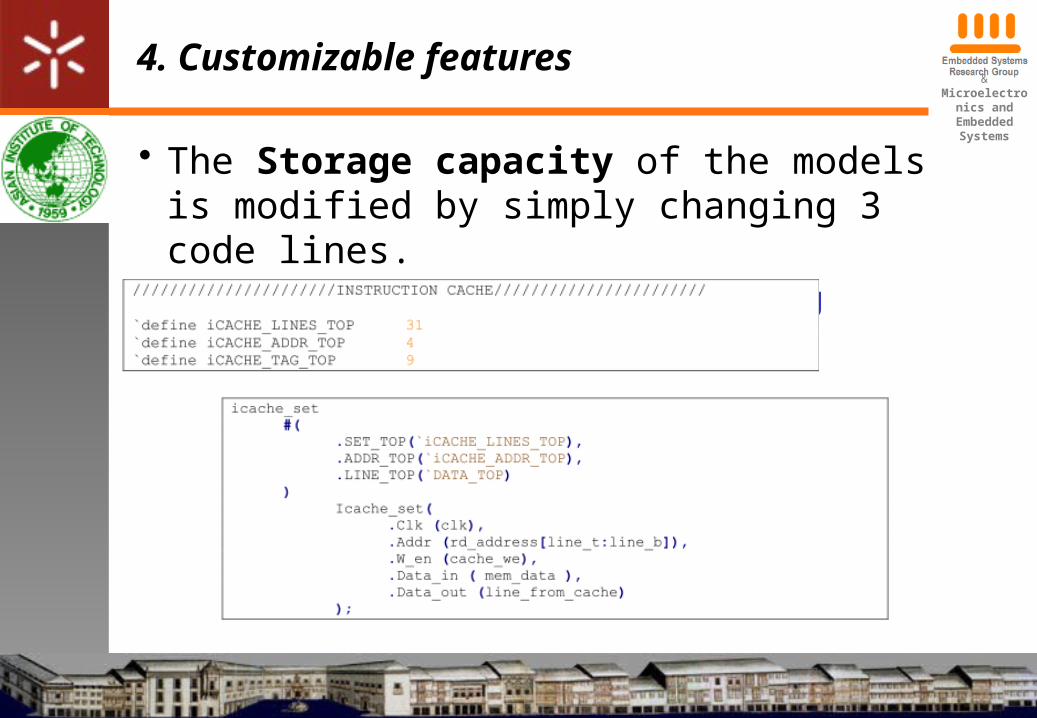
• The Storage capacity of the models is modified by simply changing 3 code lines.• Using define and parameter Verilog features
&Microelectronics and Embedded
Systems
4. Customizable features
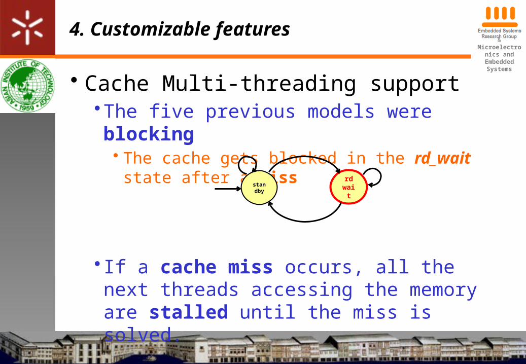
• Cache Multi-threading support•The five previous models were blocking
• The cache gets blocked in the rd_wait state after a miss
• If a cache miss occurs, all the next threads accessing the memory are stalled until the miss is solved.
rdwai
t
standby
&Microelectronics and Embedded
Systems
4. Customizable features
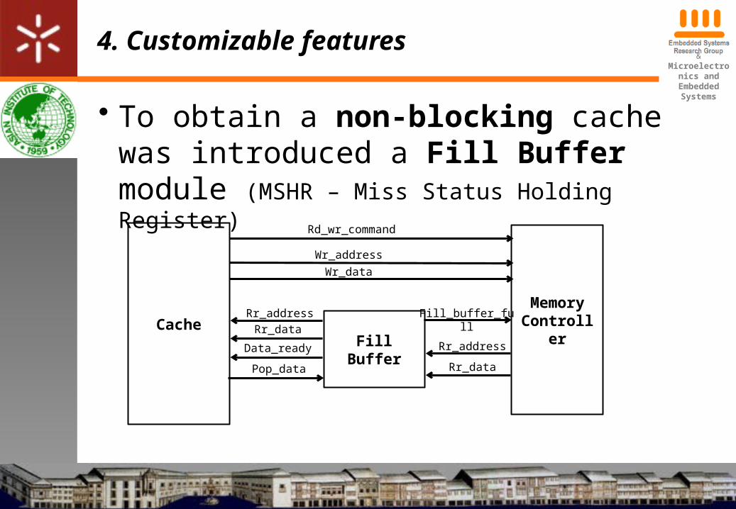
• To obtain a non-blocking cache was introduced a Fill Buffer module (MSHR – Miss Status Holding Register)
CacheMemoryControlle
rFill Buffer
Wr_address
Rd_wr_command
Wr_data
Rr_data
Rr_address
Rr_addressRr_data
Data_ready
Pop_data
Fill_buffer_full
&Microelectronics and Embedded
Systems
4. Customizable features
• The Fill Buffer temporarily stores data coming from the memory controller if the Cache is busy (performing write operation to the core)
• Later, Fill Buffer provides the data and its address to the cache.
• The cache sends a pop signal after being free and stores the pending data.
&Microelectronics and Embedded
Systems
5. Conclusions
• Front-end provides• Simple addition of instructions• Multi-threading capabilities with small area impact
• The ALU implementation provides:• Easy configurability of its structure (tree or chain) • Can be target to high performance or low power
• The Hazard Unit implements a scoreboard algorithm to reduce the pipeline stalls and improve the processor’s performance
&Microelectronics and Embedded
Systems
5. Conclusions
• Were developed and presented seven cache models to be used in the M2μP processor.
• The different models are easy to be resized, considering the application specific needs.
• The microprocessor’s prototype fabrication is being discussed with NECTEC
&Microelectronics and Embedded
Systems
6. Future perspectives
• Finish the compiler• Assembler is completed
• Add new instructions as an automatic process
• Develop a customization tool to interface a DSE application to automatically render the customization process
&Microelectronics and Embedded
Systems
6. Future perspectives
• Define the placement of the ALU modules according to the application profiling
• Implement a Memory Management Unit to extend the memory access possibilities
• Perform power measurements and apply low power consumption techniques to the caches’ implementation