ΔΙΑΛΕΞΗ 9: Advanced Memory Hierarchy Design Isssues
141
ΧΑΡΗΣ ΘΕΟΧΑΡΙΔΗΣ ([email protected]) ΗΜΥ 656 ΠΡΟΧΩΡΗΜΕΝΗ ΑΡΧΙΤΕΚΤΟΝΙΚΗ ΗΛΕΚΤΡΟΝΙΚΩΝ ΥΠΟΛΟΓΙΣΤΩΝ Εαρινό Εξάμηνο 2007 ΔΙΑΛΕΞΗ 9: Advanced Memory Hierarchy Design Isssues Ack: David Patterson, Berkeley Joseph Manzano, Univ. of Delaware
Transcript of ΔΙΑΛΕΞΗ 9: Advanced Memory Hierarchy Design Isssues
ΧΑΡΗΣ
ΘΕΟΧΑΡΙΔΗΣ
ΗΜΥ
656
ΠΡΟΧΩΡΗΜΕΝΗ
ΑΡΧΙΤΕΚΤΟΝΙΚΗ
ΗΛΕΚΤΡΟΝΙΚΩΝ
ΥΠΟΛΟΓΙΣΤΩΝ
Εαρινό
Εξάμηνο
2007
ΔΙΑΛΕΞΗ
9: Advanced Memory
Hierarchy Design Isssues
Ack: David Patterson, Berkeley
Joseph Manzano, Univ. of Delaware

Memory Hierarchy Review
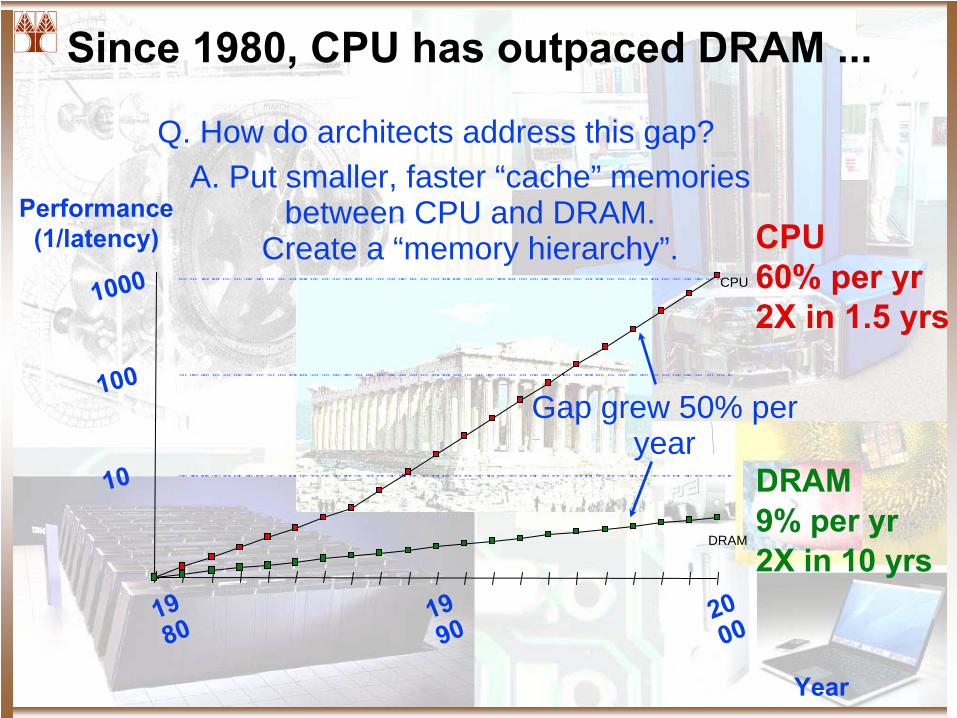
Since 1980, CPU has outpaced DRAM ...
CPU60% per yr2X in 1.5 yrs
DRAM9% per yr2X in 10 yrs
10
DRAM
CPU
Performance(1/latency)
100
1000
1980
2000
1990
Year
Gap grew 50% per year
Q. How do architects address this gap? A. Put smaller, faster “cache” memories
between CPU and DRAM. Create a “memory hierarchy”.
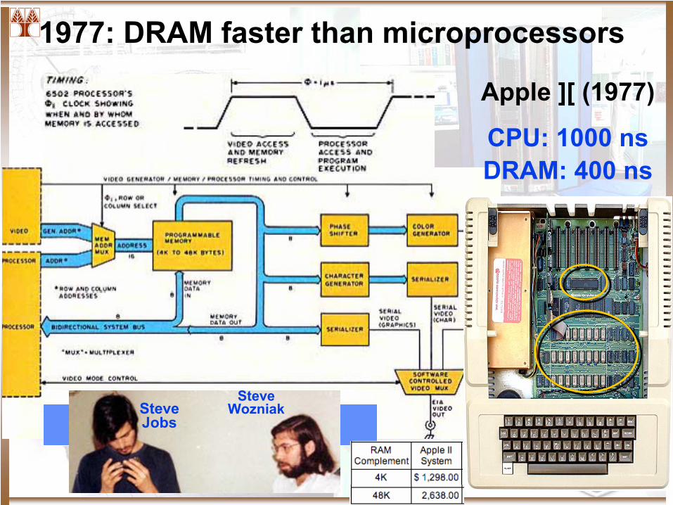
1977: DRAM faster than microprocessors
Apple ][ (1977)
Steve WozniakSteve
Jobs
CPU: 1000 nsDRAM: 400 ns

Levels of the Memory Hierarchy
CPU Registers100s Bytes<10s ns
CacheK Bytes10-100 ns1-0.1 cents/bit
Main MemoryM Bytes200ns-
500ns$.0001-.00001 cents /bitDiskG Bytes, 10 ms (10,000,000 ns)
10 -
10 cents/bit-5 -6
CapacityAccess TimeCost
Tapeinfinitesec-min10 -8
Registers
Cache
Memory
Disk
Other Devices (Tapes, etc.)
Instr. Operands
Blocks
Pages
Files
StagingXfer Unit
prog./compiler1-8 bytes
cache cntl8-128 bytes
OS512-4K bytes
user/operatorMbytes
Upper Level
Lower Level
faster
Larger
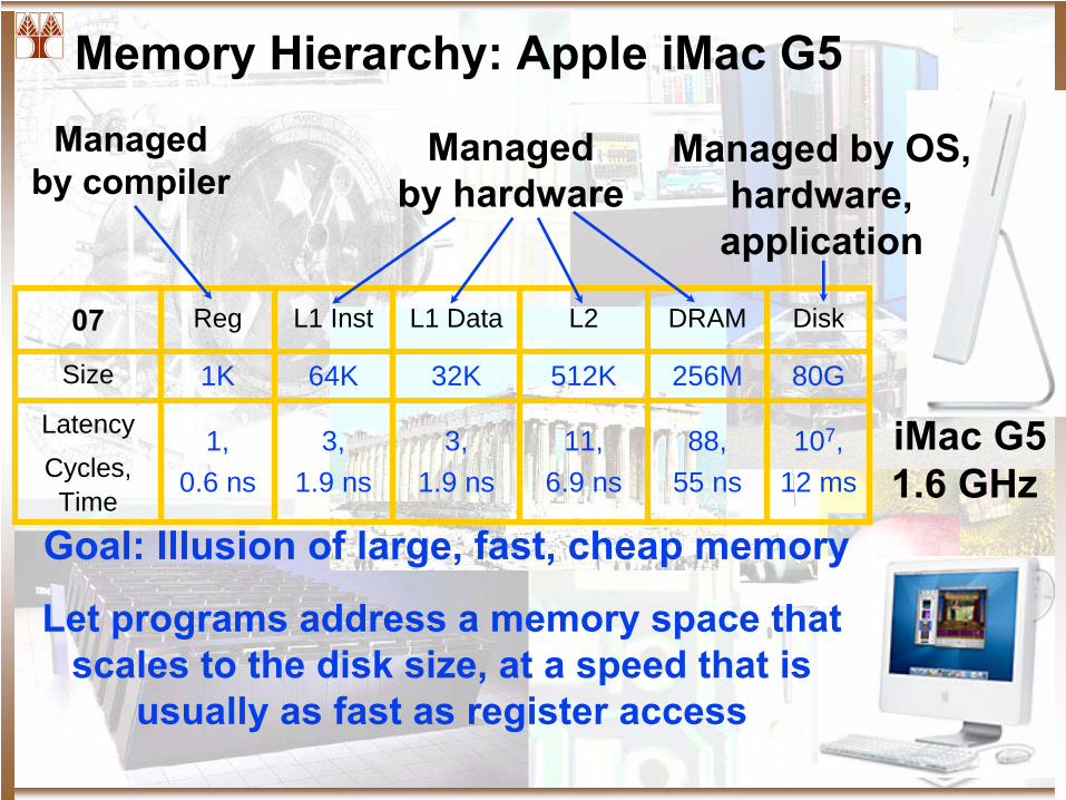
Memory Hierarchy: Apple iMac G5
iMac G51.6 GHz
07 Reg L1 Inst L1 Data L2 DRAM Disk
Size 1K 64K 32K 512K 256M 80G
LatencyCycles, Time
1,0.6 ns
3,1.9 ns
3,1.9 ns
11,6.9 ns
88,55 ns
107,12 ms
Let programs address a memory space that scales to the disk size, at a speed that is
usually as fast as register access
Managed by compiler
Managed by hardware
Managed by OS,hardware,application
Goal: Illusion of large, fast, cheap memory
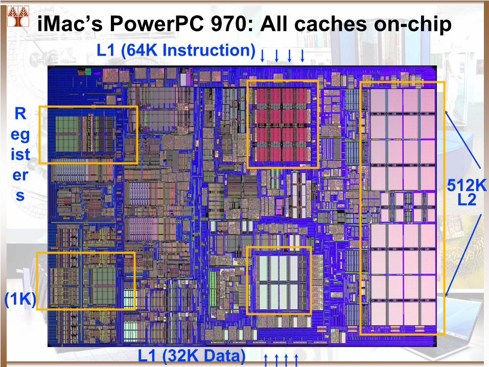
iMac’s PowerPC 970: All caches on-chip
(1K)
R eg ist er s 512K
L2
L1 (64K Instruction)
L1 (32K Data)
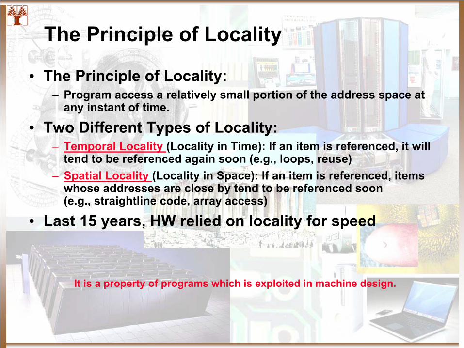
The Principle of Locality
• The Principle of Locality:– Program access a relatively small portion of the address space at
any instant of time.
• Two Different Types of Locality:– Temporal Locality (Locality in Time): If an item is referenced, it will
tend to be referenced again soon (e.g., loops, reuse)– Spatial Locality (Locality in Space): If an item is referenced, items
whose addresses are close by tend to be referenced soon (e.g., straightline
code, array access)
• Last 15 years, HW relied on locality for speed
It is a property of programs which is exploited in machine design.
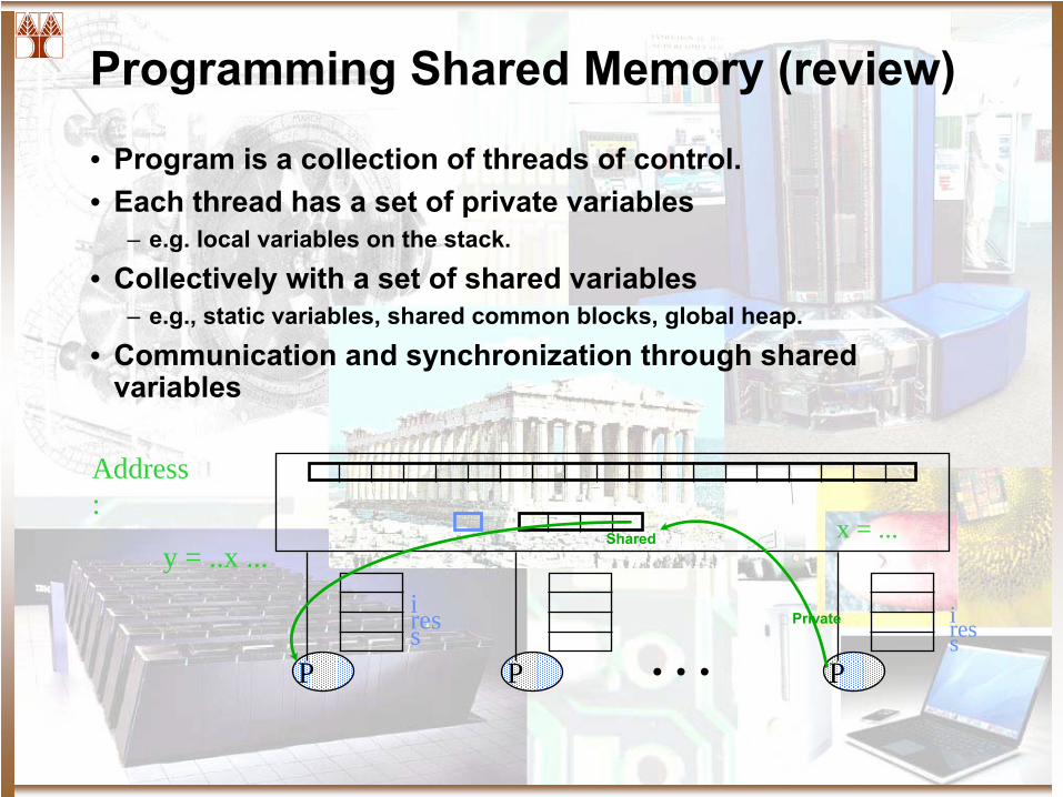
Programming Shared Memory (review)
• Program is a collection of threads of control.• Each thread has a set of private variables
– e.g. local variables on the stack.
• Collectively with a set of shared variables– e.g., static variables, shared common blocks, global heap.
• Communication and synchronization through shared variables
iressPPP
iress . . .
x = ...y = ..x ...
Address :
Shared
Private
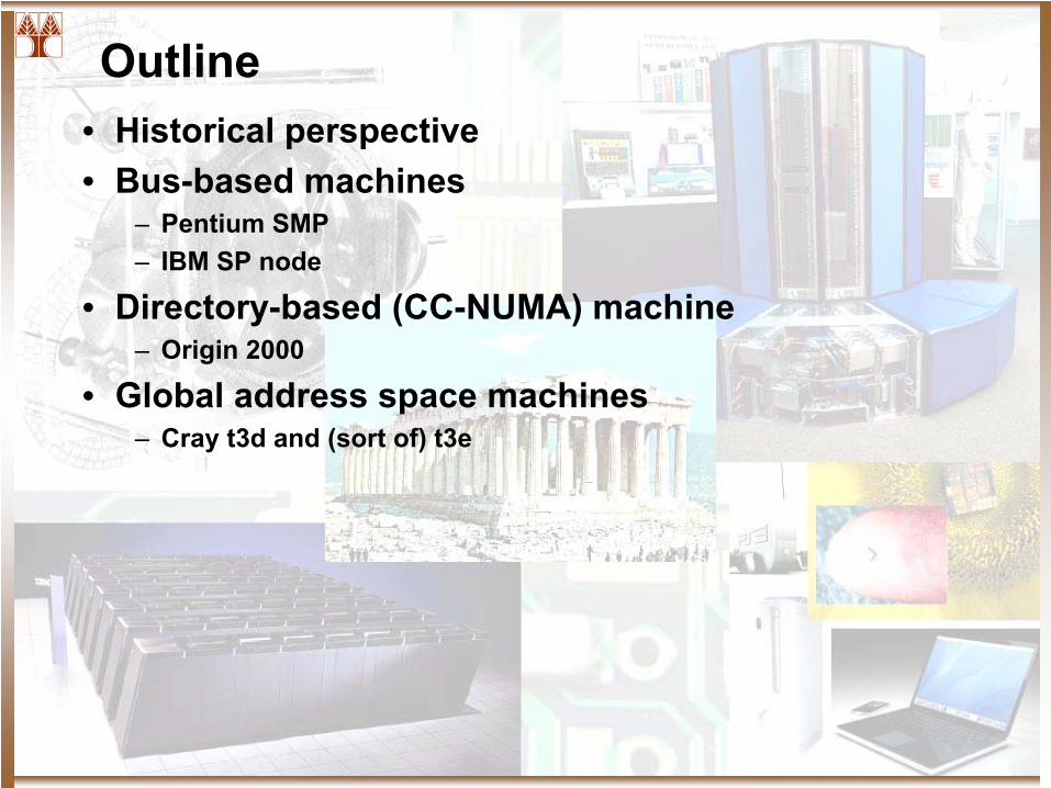
Outline• Historical perspective• Bus-based machines
– Pentium SMP– IBM SP node
• Directory-based (CC-NUMA) machine– Origin 2000
• Global address space machines– Cray t3d and (sort of) t3e
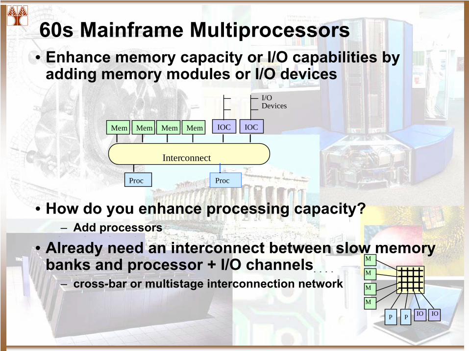
60s Mainframe Multiprocessors• Enhance memory capacity or I/O capabilities by
adding memory modules or I/O devices
• How do you enhance processing capacity?– Add processors
• Already need an interconnect between slow memory banks and processor + I/O channels
– cross-bar or multistage interconnection network
Proc
I/ODevices
Interconnect
Proc
Mem IOCMem Mem Mem IOC
P IO IOP
M
M
M
M
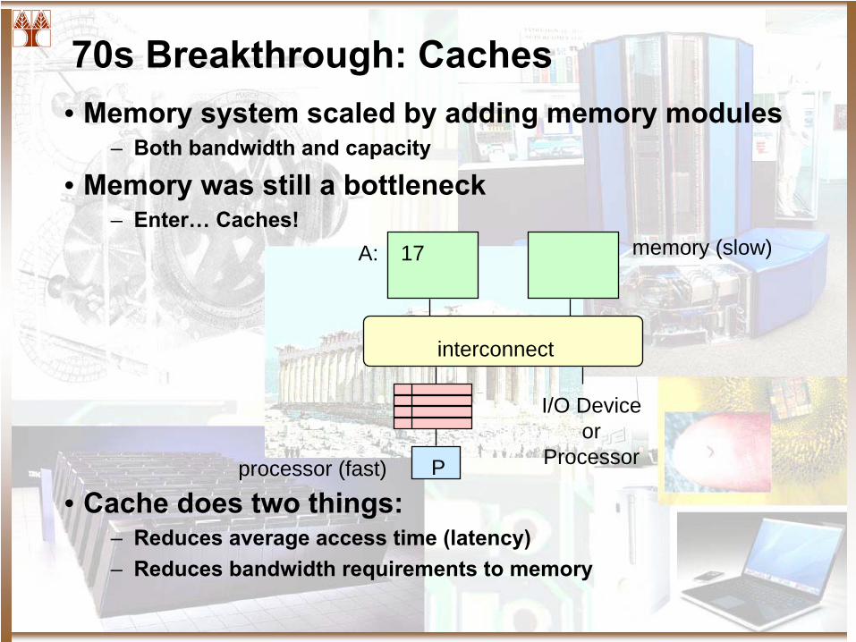
70s Breakthrough: Caches• Memory system scaled by adding memory modules
– Both bandwidth and capacity
• Memory was still a bottleneck– Enter…
Caches!
• Cache does two things:– Reduces average access time (latency)– Reduces bandwidth requirements to memory
P
memory (slow)
interconnect
I/O Deviceor
Processor
A: 17
processor (fast)
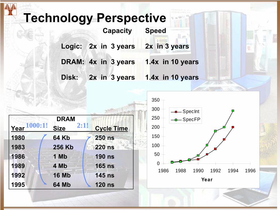
Technology Perspective
DRAMYear
Size
Cycle Time1980
64 Kb
250 ns1983
256 Kb
220 ns1986
1 Mb
190 ns1989
4 Mb
165 ns1992
16 Mb
145 ns1995
64 Mb
120 ns
1000:1! 2:1!
Capacity
Speed
Logic:
2x in 3 years
2x in 3 years
DRAM:
4x in 3 years
1.4x in 10 years
Disk:
2x in 3 years
1.4x in 10 years
0
50
100
150
200
250
300
350
1986 1988 1990 1992 1994 1996
Year
SpecIntSpecFP
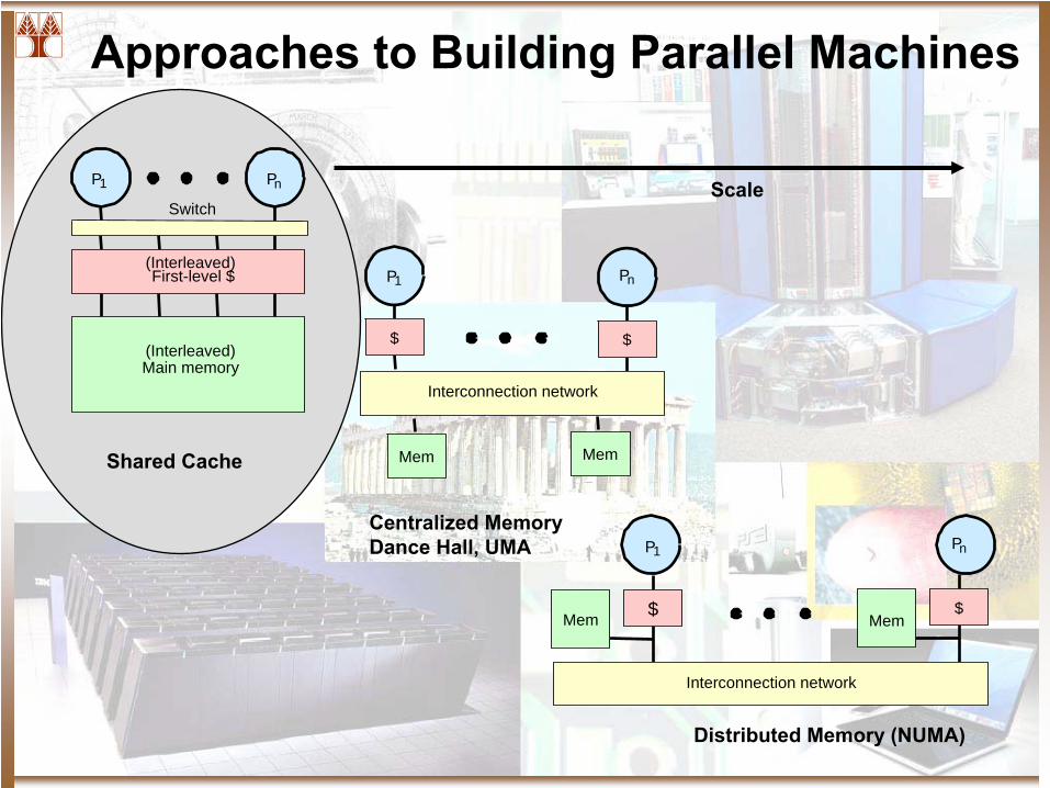
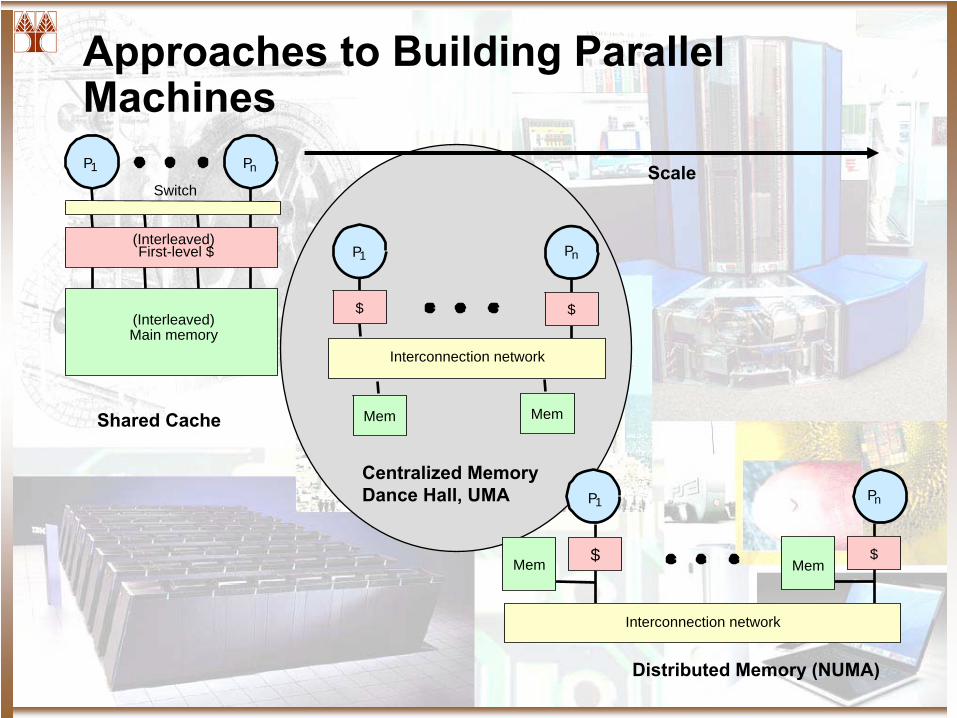
Approaches to Building Parallel Machines
P1
Switch
Main memory
Pn
(Interleaved)
(Interleaved)
First-level $
P1
$
Interconnection network
$
Pn
Mem Mem
P1
$
Interconnection network
$
Pn
Mem MemShared Cache
Centralized MemoryDance Hall, UMA
Distributed Memory (NUMA)
Scale
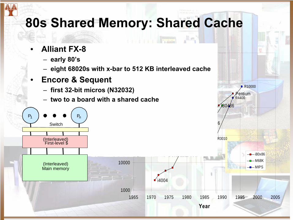
80s Shared Memory: Shared Cache
i80286
i80486
Pentium
i80386
i8086
i4004
R10000
R4400
R3010
SU MIPS
1000
10000
100000
1000000
10000000
100000000
1965 1970 1975 1980 1985 1990 1995 2000 2005
Year
Tran
sist
ors
i80x86M68KMIPS
• Alliant
FX-8– early 80’s– eight 68020s with x-bar to 512 KB interleaved cache
• Encore & Sequent– first 32-bit micros (N32032)– two to a board with a shared cache
P1
Switch
Main memory
Pn
(Interleaved)
(Interleaved)
First-level $
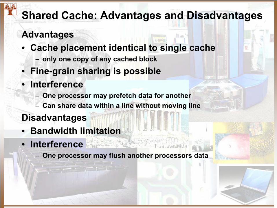
Shared Cache: Advantages and DisadvantagesAdvantages• Cache placement identical to single cache
– only one copy of any cached block
• Fine-grain sharing is possible• Interference
– One processor may prefetch
data for another– Can share data within a line without moving line
Disadvantages• Bandwidth limitation• Interference
– One processor may flush another processors data
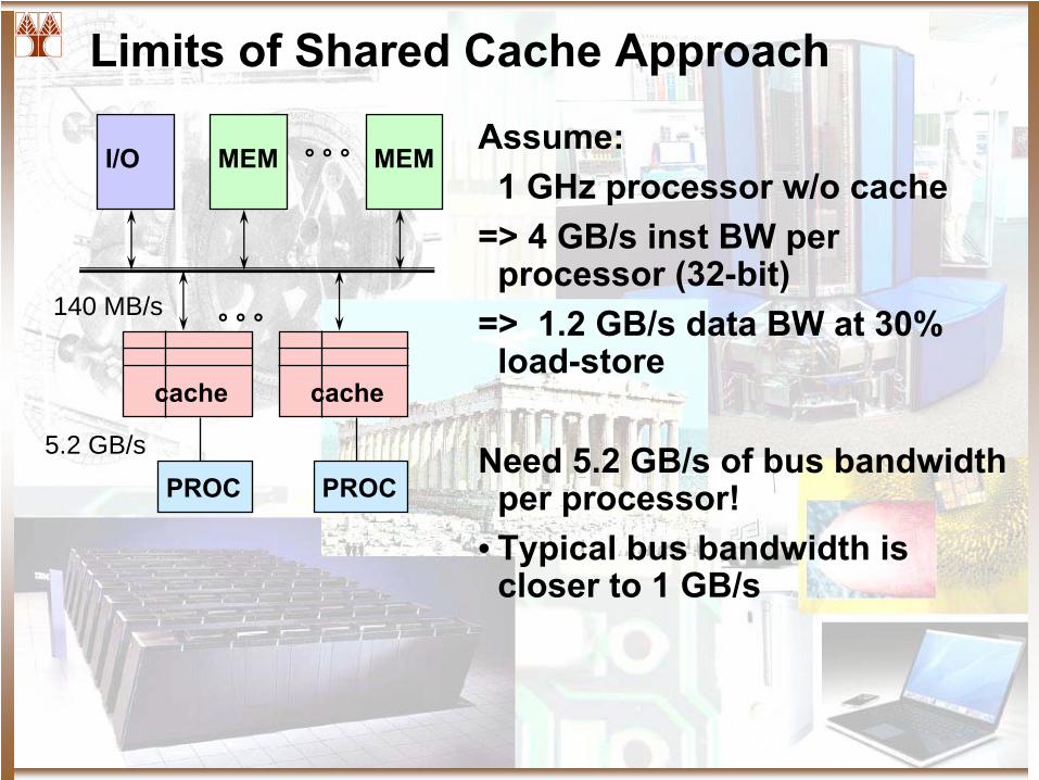
Limits of Shared Cache Approach
I/O MEM MEM° ° °
PROC
cache
PROC
cache
° ° °
Assume:1 GHz processor w/o cache
=> 4 GB/s inst BW per processor (32-bit)
=> 1.2 GB/s data BW at 30% load-store
Need 5.2 GB/s of bus bandwidth per processor!
• Typical bus bandwidth is closer to 1 GB/s
5.2 GB/s
140 MB/s
Approaches to Building Parallel MachinesP1
Switch
Main memory
Pn
(Interleaved)
(Interleaved)
First-level $
P1
$
Interconnection network
$
Pn
Mem Mem
P1
$
Interconnection network
$
Pn
Mem MemShared Cache
Centralized MemoryDance Hall, UMA
Distributed Memory (NUMA)
Scale
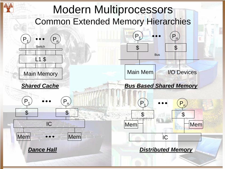
Modern Multiprocessors Common Extended Memory Hierarchies
PnP1
$ $
Main Mem
PnP1
$ $
Mem
IC
Mem
PnP1
$ $
Mem
IC
Mem
P1 Pn
L1 $
Main Memory
Switch
I/O Devices
Bus
Shared Cache Bus Based Shared Memory
Dance Hall Distributed Memory
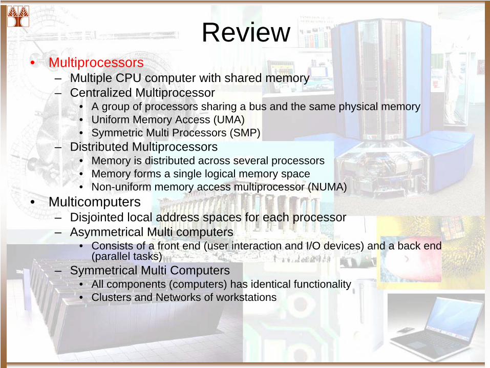
Review• Multiprocessors
– Multiple CPU computer with shared memory– Centralized Multiprocessor
• A group of processors sharing a bus and the same physical memory• Uniform Memory Access (UMA)• Symmetric Multi Processors (SMP)
– Distributed Multiprocessors• Memory is distributed across several processors• Memory forms a single logical memory space • Non-uniform memory access multiprocessor (NUMA)
• Multicomputers– Disjointed local address spaces for each processor– Asymmetrical Multi computers
• Consists of a front end (user interaction and I/O devices) and a back end (parallel tasks)
– Symmetrical Multi Computers• All components (computers) has identical functionality• Clusters and Networks of workstations
Programming Execution Models
• A set of rules to create programs• Message Passing Model
– De Facto Multicomputer Programming Model– Multiple Address Space– Explicit Communication / Implicit Synchronization
• Shared Memory Models– De Facto Multiprocessor Programming Model– Single Address Space– Implicit Communication / Explicit Synchronization
Distributed Memory MIMD
• Advantages– Less Contention– Highly Scalable– Simplified Synch– Message Passing
Synch + Comm.
• Disadvantages– Load Balancing– Deadlock / Livelock prone– Waste of Bandwidth– Overhead of small
messages
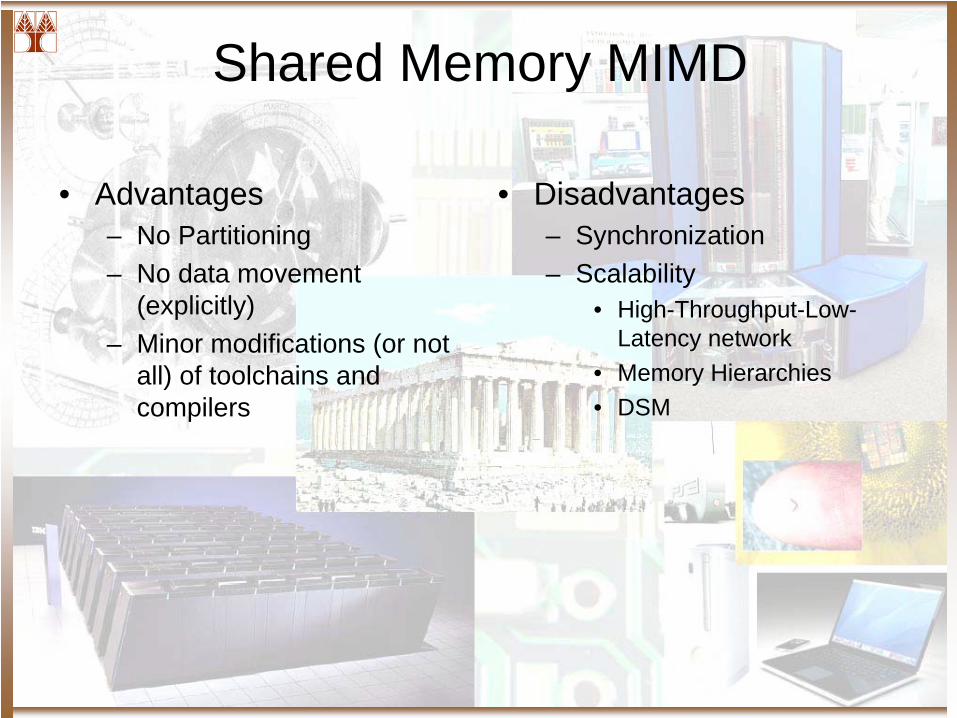
Shared Memory MIMD
• Advantages– No Partitioning– No data movement
(explicitly)– Minor modifications (or not
all) of toolchains and compilers
• Disadvantages– Synchronization– Scalability
• High-Throughput-Low- Latency network
• Memory Hierarchies• DSM
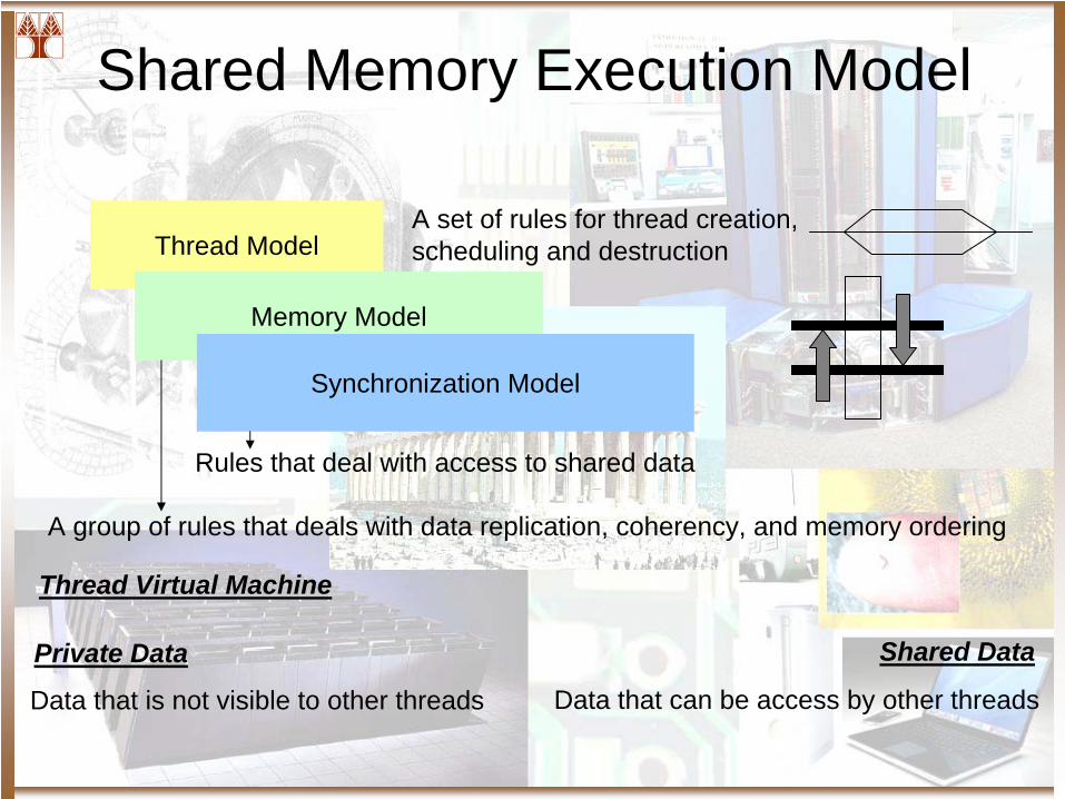
Thread Model
Memory Model
Synchronization Model
A set of rules for thread creation, scheduling and destruction
Rules that deal with access to shared data
Shared Memory Execution Model
A group of rules that deals with data replication, coherency, and memory ordering
Private Data Shared Data
Data that is not visible to other threads Data that can be access by other threads
Thread Virtual Machine
User Level Shared Memory Support
• Shared Address Space Support and Management
• Access Control and Management– Memory Consistency Model– Cache Management Mechanism
Grand Challenge Problems
• Shared Memory Multiprocessor Effective at a number of thousand units
• Optimize and Compile parallel applications• Main Areas: Assumptions about
– Memory Coherency– Memory Consistency
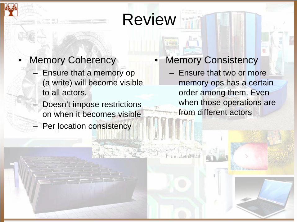
Review
• Memory Coherency– Ensure that a memory op
(a write) will become visible to all actors.
– Doesn’t impose restrictions on when it becomes visible
– Per location consistency
• Memory Consistency– Ensure that two or more
memory ops has a certain order among them. Even when those operations are from different actors
Foundation for Building Shared
Memory Machines
Memory Consistency and Coherency
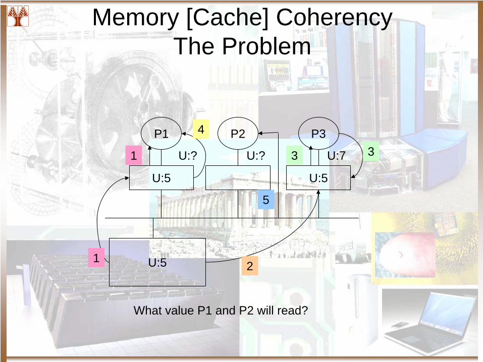
Memory [Cache] Coherency The Problem
P1 P2 P3
U:5 U:5
U:51
4
U:? U:? U:7
2
3
5
What value P1 and P2 will read?
1 3

Memory Consistency Problem
B = 0…A = 1
L1: print B
A = 0…B = 1
L2: print A
Assume that L1 and L2 are issue only after the other 4 instructions have been completed.What are the possible values that are printed on the screen? Is 0, 0 a possible combination?
The MCM: A software and hardware contract
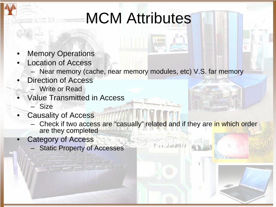
MCM Attributes
• Memory Operations• Location of Access
– Near memory (cache, near memory modules, etc) V.S. far memory• Direction of Access
– Write or Read• Value Transmitted in Access
– Size• Causality of Access
– Check if two access are “casually” related and if they are in which order are they completed
• Category of Access– Static Property of Accesses
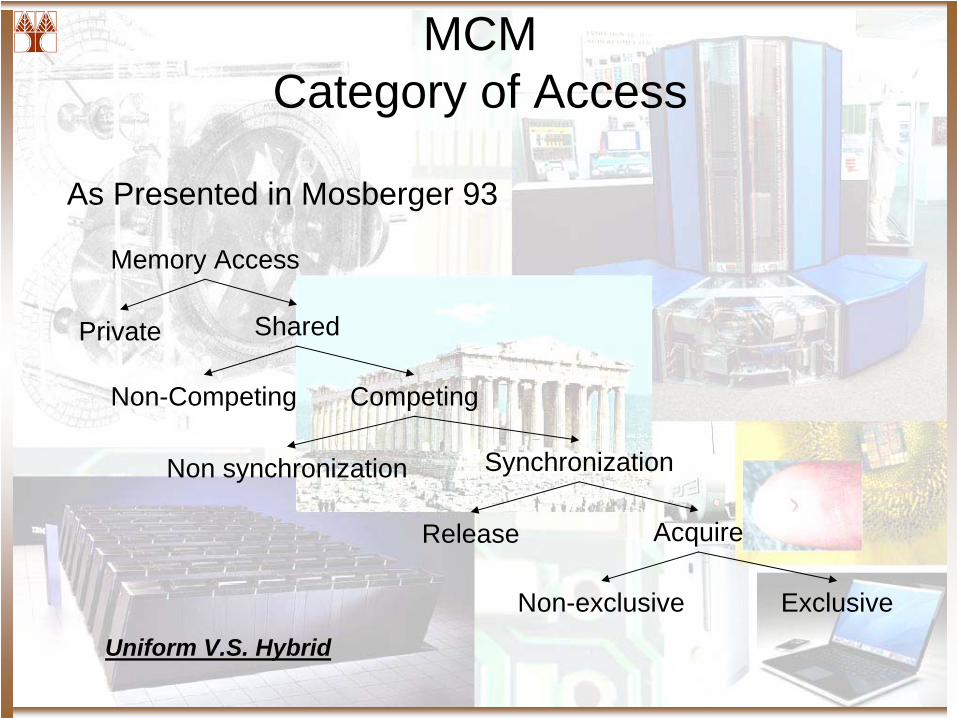
MCM Category of Access
As Presented in Mosberger 93
Memory Access
Private Shared
CompetingNon-Competing
SynchronizationNon synchronization
AcquireRelease
ExclusiveNon-exclusiveUniform V.S. Hybrid
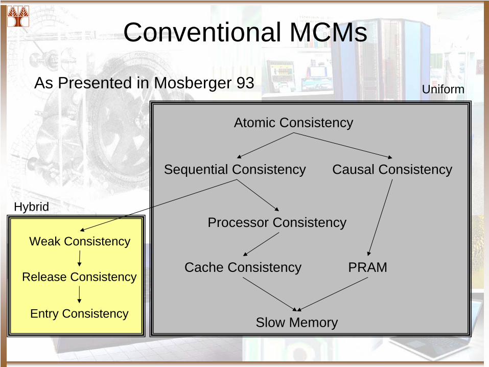
Conventional MCMs
As Presented in Mosberger 93
Atomic Consistency
Sequential Consistency Causal Consistency
Processor Consistency
Cache Consistency PRAM
Slow Memory
Weak Consistency
Release Consistency
Entry Consistency
Uniform
Hybrid
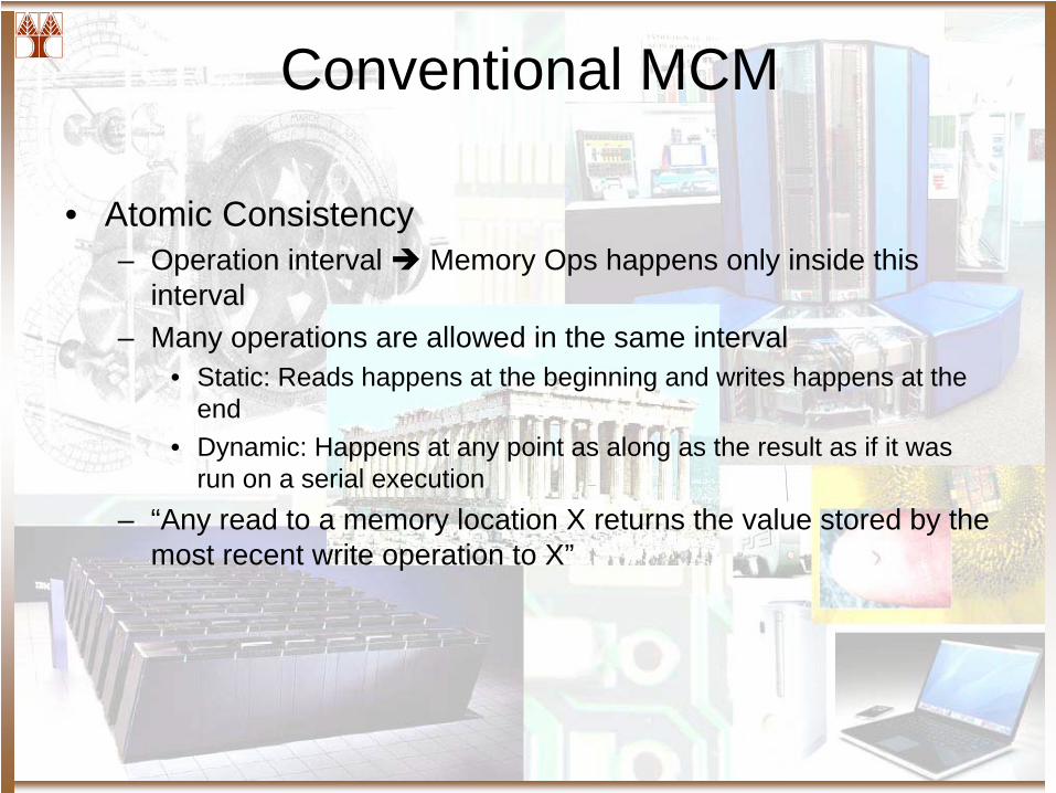
Conventional MCM
• Atomic Consistency– Operation interval Memory Ops happens only inside this
interval– Many operations are allowed in the same interval
• Static: Reads happens at the beginning and writes happens at the end
• Dynamic: Happens at any point as along as the result as if it was run on a serial execution
– “Any read to a memory location X returns the value stored by the most recent write operation to X”
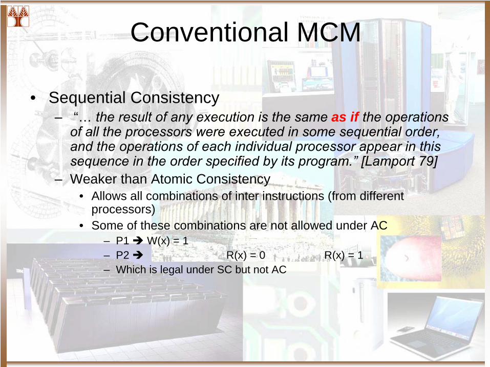
Conventional MCM
• Sequential Consistency– “… the result of any execution is the same as if the operations
of all the processors were executed in some sequential order, and the operations of each individual processor appear in this sequence in the order specified by its program.”
[Lamport
79]– Weaker than Atomic Consistency
• Allows all combinations of inter instructions (from different processors)
• Some of these combinations are not allowed under AC– P1 W(x) = 1– P2 R(x) = 0 R(x) = 1– Which is legal under SC but not AC
Conventional MCM
• Causal Consistency– Events (writes) that are causally related must be seen
in the same order by all processors.• Example: W1 (x), R2 (x), W2 (y) are casually related because
the value of y might depend on the value written by x
– Unrelated causal events can be seen in any order
Conventional MCM
• Cache Consistency– Synonym with Cache coherence– Sequential ordering per location basis
• SC ensures sequential ordering for all memory locations– Cache consistency is included in SC but not the other way
around.• Pipeline RAM
– Single Processor Writes can be pipelined w/o stalling– All writes from other processors are considered concurrent
• They can be seen in different order
Conventional MCM
• Processor Coherence (Goodman’s 89)– PRAM and Coherence united– Processors agrees in the order of writes from a single
processor but might disagree in the order of writes of different processors as long as they are to different locations
– Stronger than coherence but weaker than sequential
Conventional MCM
• Weak Consistency– Following restrictions
• Any Access to synchronized variables are SC• No Access to a synch variable is issued until all previous data
access are performed• No access is issued by a processor until a previous synch access is
performed– Synch Access == Fence– A program behave as SC under WC if
• No data race• Synchronization is visible to the memory system
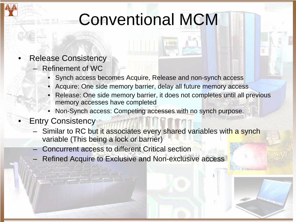
Conventional MCM
• Release Consistency– Refinement of WC
• Synch access becomes Acquire, Release and non-synch access• Acquire: One side memory barrier, delay all future memory access• Release: One side memory barrier, it does not completes until all previous
memory accesses have completed• Non-Synch access: Competing accesses with no synch purpose.
• Entry Consistency– Similar to RC but it associates every shared variables with a synch
variable (This being a lock or barrier)– Concurrent access to different Critical section– Refined Acquire to Exclusive and Non-exclusive access
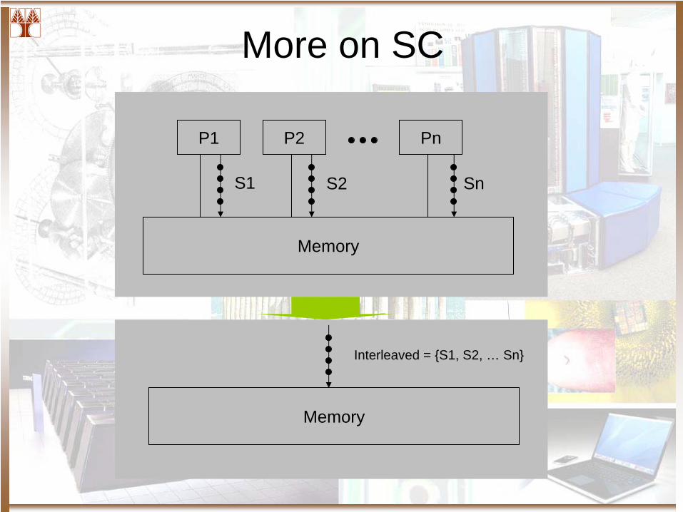
More on SC
P1 P2 Pn
Memory
Memory
Interleaved = S1, S2, … Sn
S1 S2 Sn
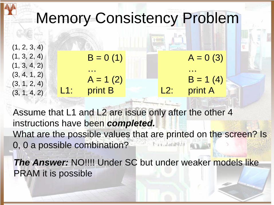
Memory Consistency Problem
B = 0 (1)…A = 1 (2)
L1: print B
A = 0 (3)…B = 1 (4)
L2: print A
Assume that L1 and L2 are issue only after the other 4 instructions have been completed.What are the possible values that are printed on the screen? Is 0, 0 a possible combination?
The Answer: NO!!!! Under SC but under weaker models like PRAM it is possible
(1, 2, 3, 4)(1, 3, 2, 4)(1, 3, 4, 2)(3, 4, 1, 2)(3, 1, 2, 4)(3, 1, 4, 2)
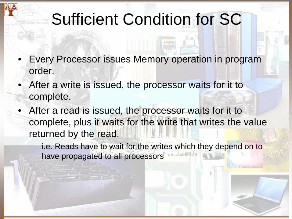
Sufficient Condition for SC
• Every Processor issues Memory operation in program order.
• After a write is issued, the processor waits for it to complete.
• After a read is issued, the processor waits for it to complete, plus it waits for the write that writes the value returned by the read.– i.e. Reads have to wait for the writes which they depend on to
have propagated to all processors
One more Thing …
• Scratch Pad– A private section of memory to each processing unit– Non coherent and therefore non consistent– Own Rd and Wr ports– High Speed Access– Separate Address space as seen by the processor– Good or Bad?
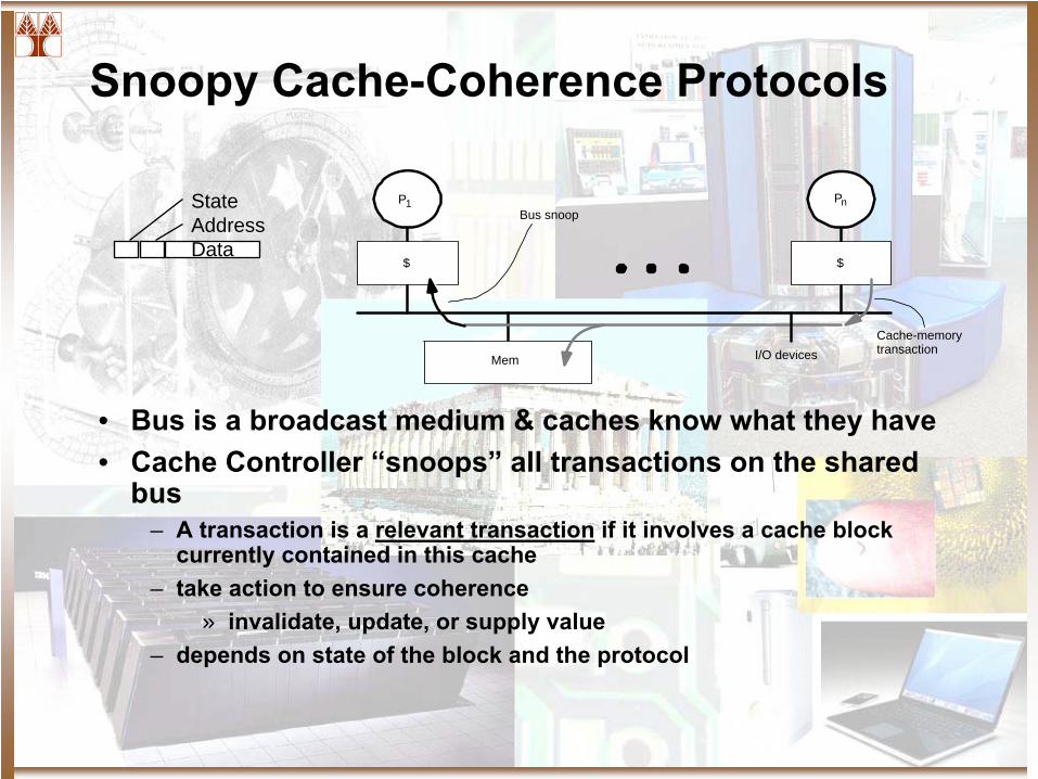
Snoopy Cache-Coherence Protocols
• Bus is a broadcast medium & caches know what they have• Cache Controller “snoops”
all transactions on the shared bus
– A transaction is a relevant transaction
if it involves a cache block currently contained in this cache
– take action to ensure coherence» invalidate, update, or supply value
– depends on state of the block and the protocol
StateAddressData
I/O devicesMem
P1
$
Bus snoop
$
Pn
Cache-memorytransaction
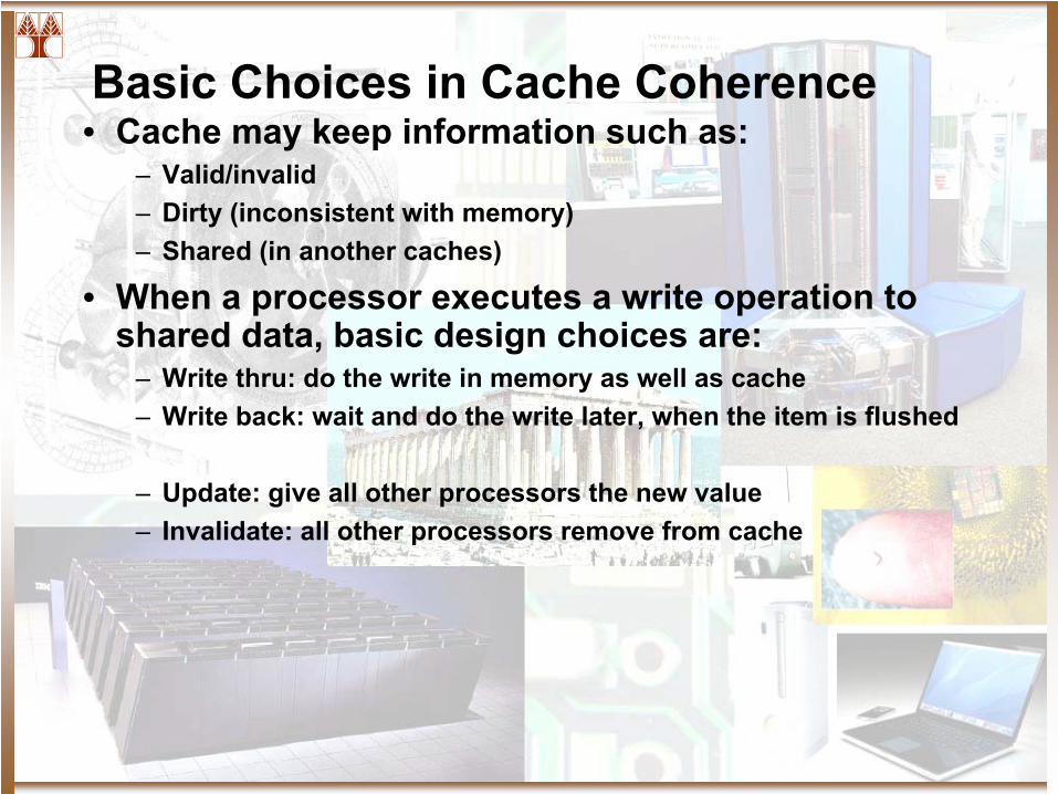
Basic Choices in Cache Coherence• Cache may keep information such as:
– Valid/invalid– Dirty (inconsistent with memory)– Shared (in another caches)
• When a processor executes a write operation to shared data, basic design choices are:
– Write thru: do the write in memory as well as cache– Write back: wait and do the write later, when the item is flushed
– Update: give all other processors the new value– Invalidate: all other processors remove from cache
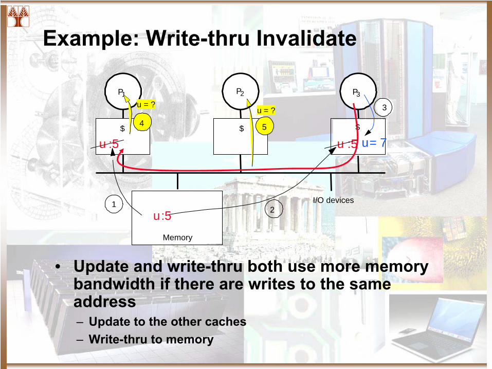
Example: Write-thru Invalidate
• Update and write-thru both use more memory bandwidth if there are writes to the same address– Update to the other caches– Write-thru to memory
I/O devices
Memory
P1
$ $ $
P2 P3
5
u = ?4
u = ?
u:51
u :5
2
u :5
3
u= 7
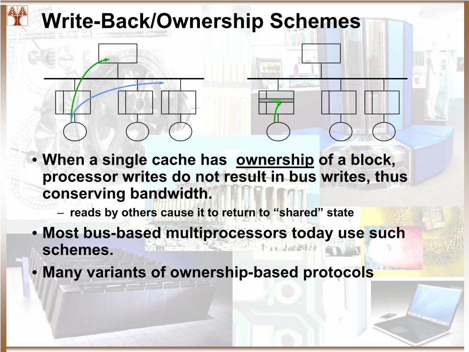
Write-Back/Ownership Schemes
• When a single cache has ownership
of a block, processor writes do not result in bus writes, thus conserving bandwidth.
– reads by others cause it to return to “shared”
state
• Most bus-based multiprocessors today use such schemes.
• Many variants of ownership-based protocols
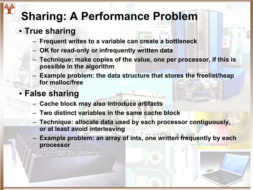
Sharing: A Performance Problem• True sharing
– Frequent writes to a variable can create a bottleneck– OK for read-only or infrequently written data– Technique: make copies of the value, one per processor, if this is
possible in the algorithm– Example problem: the data structure that stores the freelist/heap
for malloc/free
• False sharing– Cache block may also introduce artifacts– Two distinct variables in the same cache block– Technique: allocate data used by each processor contiguously,
or at least avoid interleaving– Example problem: an array of ints, one written frequently by each
processor
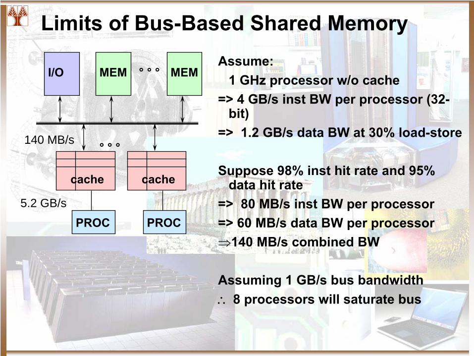
Limits of Bus-Based Shared Memory
I/O MEM MEM° ° °
PROC
cache
PROC
cache
° ° °
Assume:1 GHz processor w/o cache
=> 4 GB/s inst BW per processor (32-
bit)
=> 1.2 GB/s data BW at 30% load-store
Suppose 98% inst hit rate and 95% data hit rate
=> 80 MB/s inst BW per processor=> 60 MB/s data BW per processor⇒140 MB/s combined BW
Assuming 1 GB/s bus bandwidth∴
8 processors will saturate bus
5.2 GB/s
140 MB/s
Cache Coherency Protocols
An Intro to Cache Coherence Protocols
Outline
• Review of Cache Architecture / Organization• The cache protocol• Bus SNOOPY based cache protocol: MESI• Directory Based cache protocol• DASH Architecture
Cache Coherency
• The Coherency Problem– A processor should have exclusive access to a shared variable
when writing and should get the “most recent” value when reading.
• Solution– When writing
• (1) Invalidate all copies• (2) Broadcast to everyone the new copy
– When reading• Finding the most recent copy
– Can be tricky
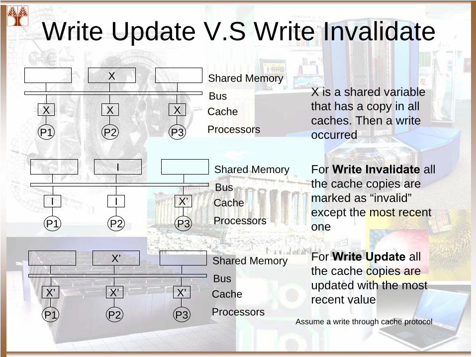
Write Update V.S Write Invalidate
X’
X’
P1
X’
P2
X’
P3
Shared Memory
BusCache
Processors
I
I
P1
I
P2
X’
P3
Shared Memory
BusCache
Processors
X
X
P1
X
P2
X
P3
Shared Memory
BusCache
Processors
X is a shared variable that has a copy in all caches. Then a write occurred
For Write Invalidate
all the cache copies are marked as “invalid” except the most recent one
For Write Update
all the cache copies are updated with the most recent value
Assume a write through cache protocol
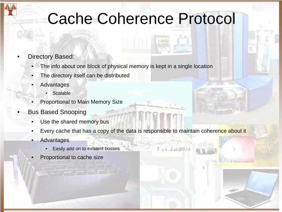
Cache Coherence Protocol
• Directory Based:• The info about one block of physical memory is kept in a single location
• The directory itself can be distributed
• Advantages• Scalable
• Proportional to Main Memory Size
• Bus Based Snooping• Use the shared memory bus
• Every cache that has a copy of the data is responsible to maintain coherence about it
• Advantages• Easily add on to existent busses
• Proportional to cache size
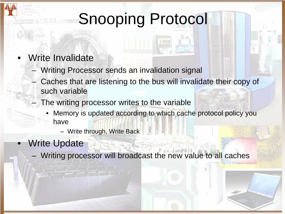
Snooping Protocol
• Write Invalidate– Writing Processor sends an invalidation signal– Caches that are listening to the bus will invalidate their copy of
such variable– The writing processor writes to the variable
• Memory is updated according to which cache protocol policy you have
– Write through, Write Back
• Write Update– Writing processor will broadcast the new value to all caches
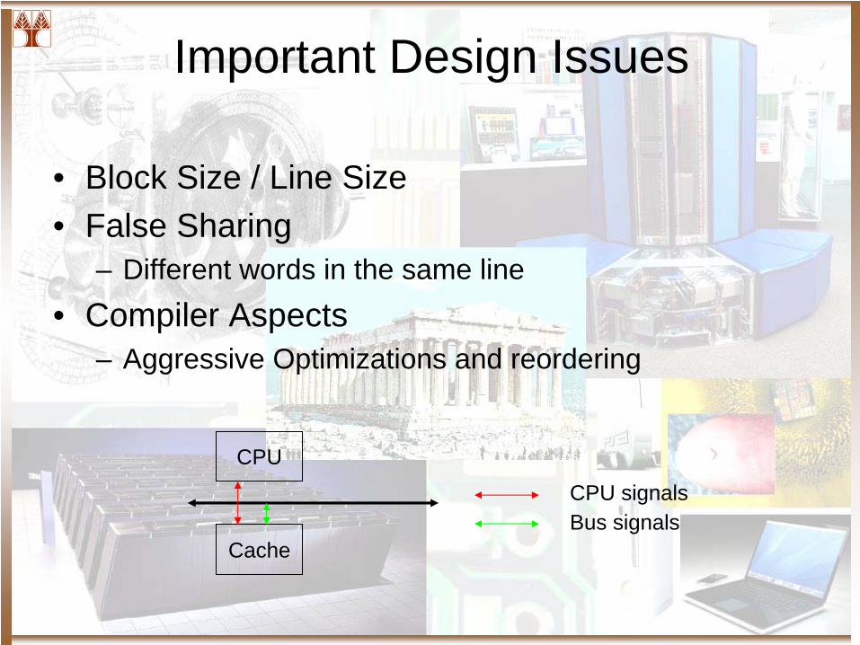
Important Design Issues
• Block Size / Line Size• False Sharing
– Different words in the same line• Compiler Aspects
– Aggressive Optimizations and reordering
CPU
Cache
CPU signalsBus signals
Finite Automata for Cache Protocols
• State Transactions– Read Misses– Write Hits – Write Misses
• Type of Outputs– Bus Signals and CPU actions
Issues of Snoop-Based Cache Coherence
• Subtle issues:
• Correctness: atomicity issues, deadlock/ livelock / starvation issues
• Performance: pipelining of memory ops
• Minimum hardware cost
Directory Based Protocols
• Reason– Bus based protocols may generate too much traffic– Multi level IC may not have efficient broadcasting
capabilities as a system bus• Directory Based system
– A directory with an entry per memory location– Central V.S. Distributed

“Modified, Shared, Invalid”
An Intro to the “MSI” family
Requirement for Implementation
• Stores to each memory location occurs in program order
• All processing elements see such order if they access the same memory location
• Only one processor has the write privilege at a time.
Implementation
• If Read(X)– Hit: Just copy– Miss: Find the location residence of X
• Memory, other cache, others• Receive a legal copy
• If Write(X)– Acquire Ownership and / or Exclusivity
• Note: Assume a Write Back – Write Invalidate Cache Protocol
Cache Protocols as FA
• Finite Automata– A graph in which vertex are states and edges are transitions– Usually, a transition (an edge) will be labeled with a 2-tuple a / b where
a is the input action that produced the state change and b is an action that will result from this state change.
• The input action may be, in fact, many actions, the same goes to the output action
• FA as cache protocols – A vertex is the state of a given cache line– The transitions may be produced by
• Processor signals• Bus actions
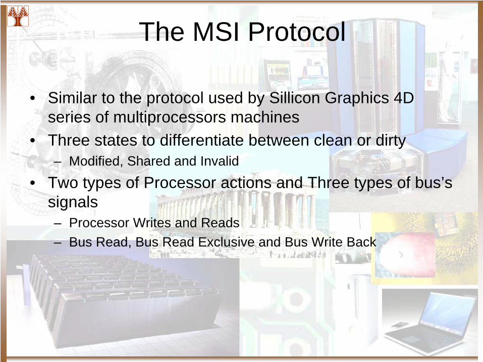
The MSI Protocol
• Similar to the protocol used by Sillicon Graphics 4D series of multiprocessors machines
• Three states to differentiate between clean or dirty– Modified, Shared and Invalid
• Two types of Processor actions and Three types of bus’s signals– Processor Writes and Reads– Bus Read, Bus Read Exclusive and Bus Write Back
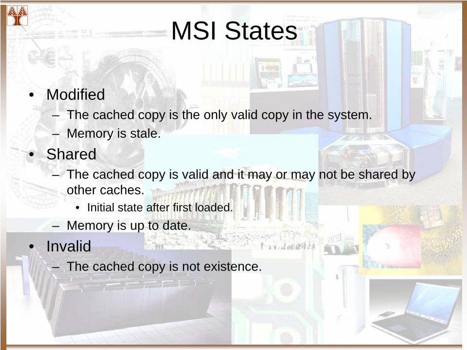
MSI States
• Modified– The cached copy is the only valid copy in the system.– Memory is stale.
• Shared– The cached copy is valid and it may or may not be shared by
other caches.• Initial state after first loaded.
– Memory is up to date.
• Invalid– The cached copy is not existence.
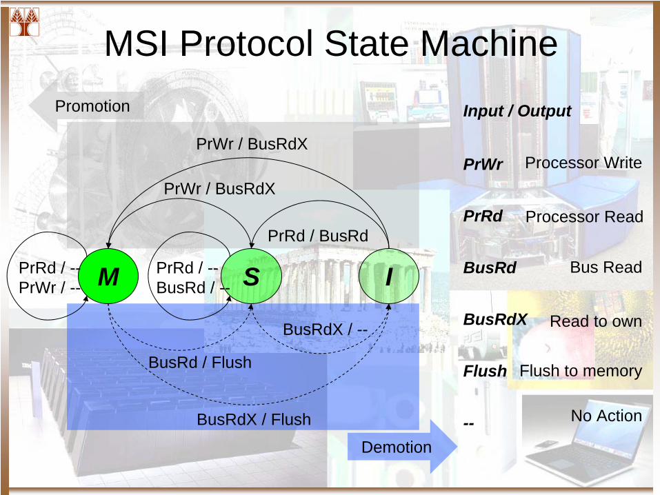
MSI Protocol State MachinePromotion
M S I
Demotion
PrRd / --PrWr / --
PrRd / --BusRd / --
BusRdX / Flush
BusRdX / --
BusRd / Flush
PrWr / BusRdX
PrRd / BusRd
PrWr / BusRdXPrWr
PrRd
BusRd
BusRdX
Flush
--
Processor Write
Processor Read
Bus Read
Read to own
Flush to memory
No Action
Input / Output
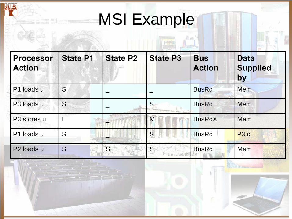
MSI Example
Processor Action
State P1 State P2 State P3 Bus Action
Data Supplied by
P1 loads u S _ _ BusRd Mem
P3 loads u S _ S BusRd Mem
P3 stores u I _ M BusRdX Mem
P1 loads u S _ S BusRd P3 c
P2 loads u S S S BusRd Mem
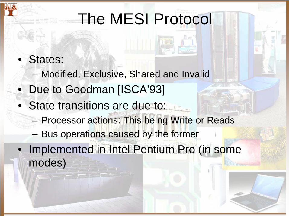
The MESI Protocol
• States:– Modified, Exclusive, Shared and Invalid
• Due to Goodman [ISCA’93]• State transitions are due to:
– Processor actions: This being Write or Reads– Bus operations caused by the former
• Implemented in Intel Pentium Pro (in some modes)
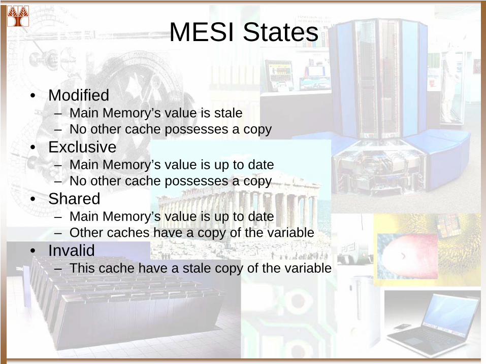
MESI States
• Modified– Main Memory’s value is stale– No other cache possesses a copy
• Exclusive– Main Memory’s value is up to date– No other cache possesses a copy
• Shared– Main Memory’s value is up to date– Other caches have a copy of the variable
• Invalid– This cache have a stale copy of the variable
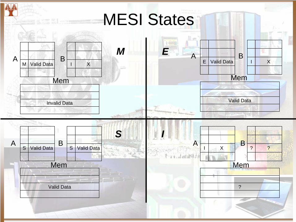
MESI States
Valid DataM XI
Invalid Data
Valid DataE XI
Valid Data
Valid DataS Valid DataS
Valid Data
XI ??
?
A B
Mem
A B
Mem
A B
Mem
A B
Mem
M E
S I
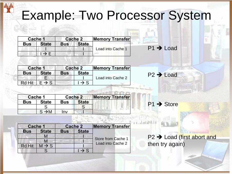
Example: Two Processor SystemCache 1 Cache 2
Bus State Bus StateI I
Memory Transfer
Load into Cache 1I E I
Cache 1 Cache 2Bus State Bus State
E I
Memory Transfer
Load into Cache 2Rd Hit E S I S
Cache 1 Cache 2Bus State Bus State
S S
Memory Transfer
S M Inv I
Cache 1 Cache 2Bus State Bus State
M I
Memory Transfer
Store from Cache 1Load into Cache 2M I
Rd Hit M S IS I S
P1 Load
P2 Load
P1 Store
P2 Load (first abort and then try again)
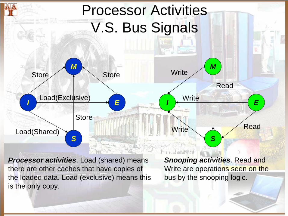
Processor Activities V.S. Bus Signals
M
I E
S
M
I E
S
Store Store
Store
Load(Shared)
Load(Exclusive)
Write
Write
Write
Read
Read
Processor activities. Load (shared) means there are other caches that have copies of the loaded data. Load (exclusive) means this is the only copy.
Snooping activities. Read and Write are operations seen on the bus by the snooping logic.
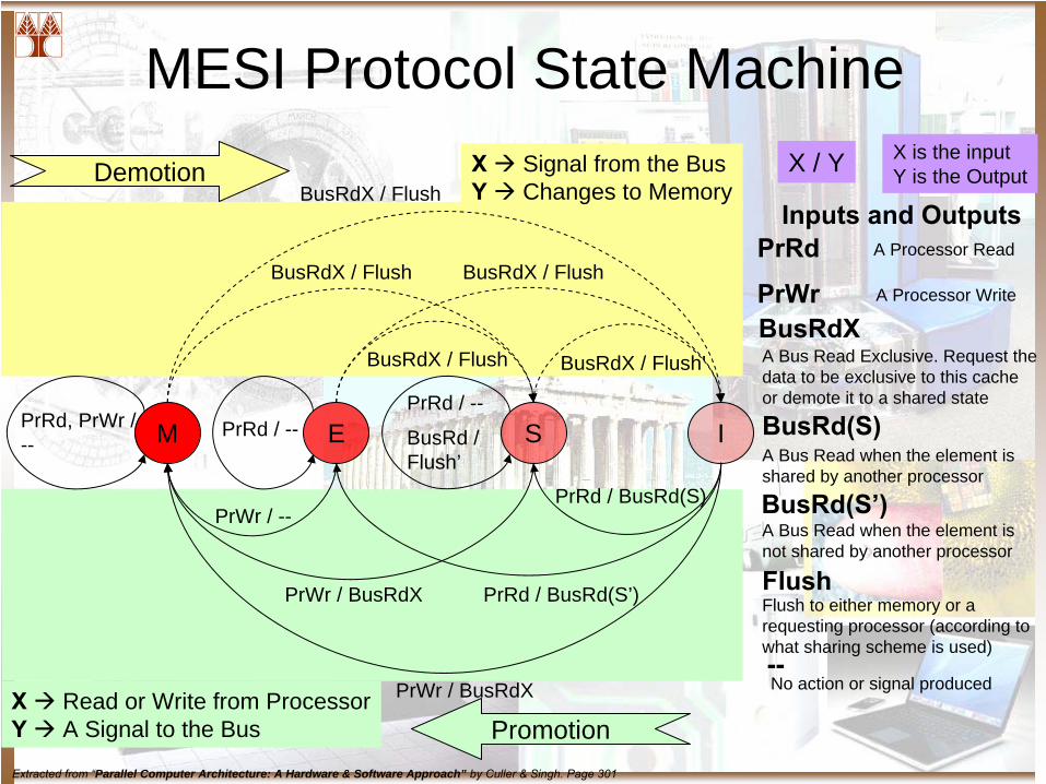
MESI Protocol State Machine
M E S IPrRd, PrWr / --
PrRd / --PrRd / --
BusRd / Flush’
BusRdX / Flush
BusRdX / Flush BusRdX / Flush
BusRdX / Flush BusRdX / Flush’
PrWr / BusRdX
PrWr / BusRdX PrRd / BusRd(S’)
PrWr / --PrRd / BusRd(S)
Demotion
Promotion
X Signal from the BusY Changes to Memory
X Read or Write from ProcessorY A Signal to the Bus
X / Y X is the inputY is the Output
Inputs and OutputsPrRd
PrWrBusRdX
BusRd(S)
BusRd(S’)
Flush
--
A Processor Read
A Processor Write
A Bus Read Exclusive. Request the data to be exclusive to this cache or demote it to a shared state
A Bus Read when the element is shared by another processor
A Bus Read when the element is not shared by another processor
Flush to either memory or a requesting processor (according to what sharing scheme is used)
No action or signal produced
Extracted from “Parallel Computer Architecture: A Hardware & Software Approach” by Culler & Singh. Page 301
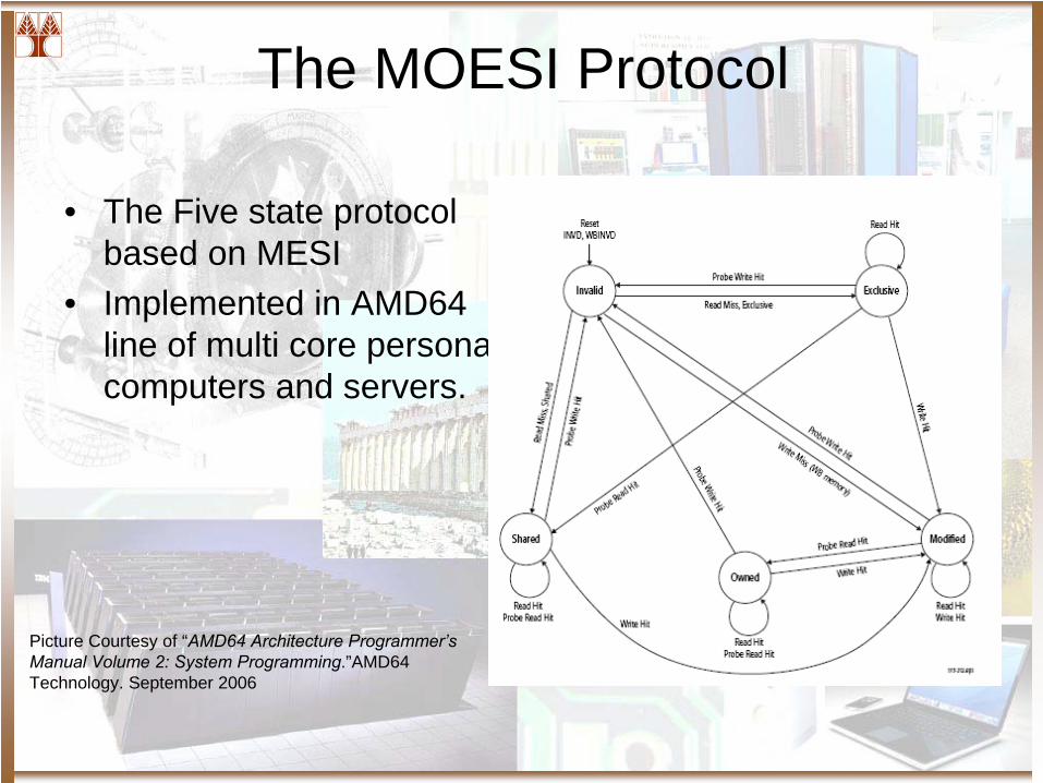
The MOESI Protocol
• The Five state protocol based on MESI
• Implemented in AMD64 line of multi core personal computers and servers.
Picture Courtesy of “AMD64 Architecture Programmer’s Manual Volume 2: System Programming.”AMD64 Technology. September 2006
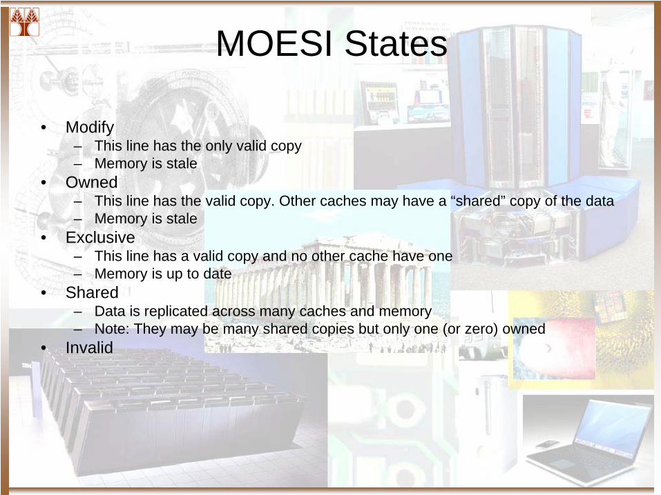
MOESI States
• Modify– This line has the only valid copy– Memory is stale
• Owned– This line has the valid copy. Other caches may have a “shared” copy of the data– Memory is stale
• Exclusive– This line has a valid copy and no other cache have one– Memory is up to date
• Shared– Data is replicated across many caches and memory– Note: They may be many shared copies but only one (or zero) owned
• Invalid
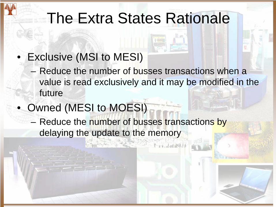
The Extra States Rationale
• Exclusive (MSI to MESI)– Reduce the number of busses transactions when a
value is read exclusively and it may be modified in the future
• Owned (MESI to MOESI)– Reduce the number of busses transactions by
delaying the update to the memory
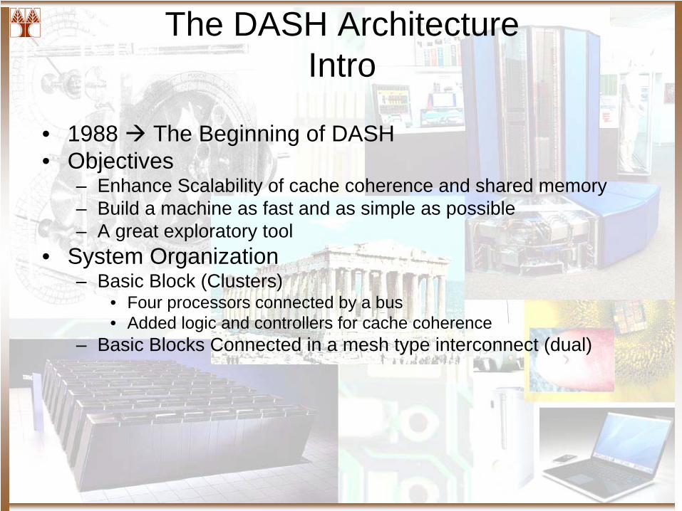
The DASH Architecture Intro
• 1988 The Beginning of DASH• Objectives
– Enhance Scalability of cache coherence and shared memory– Build a machine as fast and as simple as possible– A great exploratory tool
• System Organization– Basic Block (Clusters)
• Four processors connected by a bus• Added logic and controllers for cache coherence
– Basic Blocks Connected in a mesh type interconnect (dual)
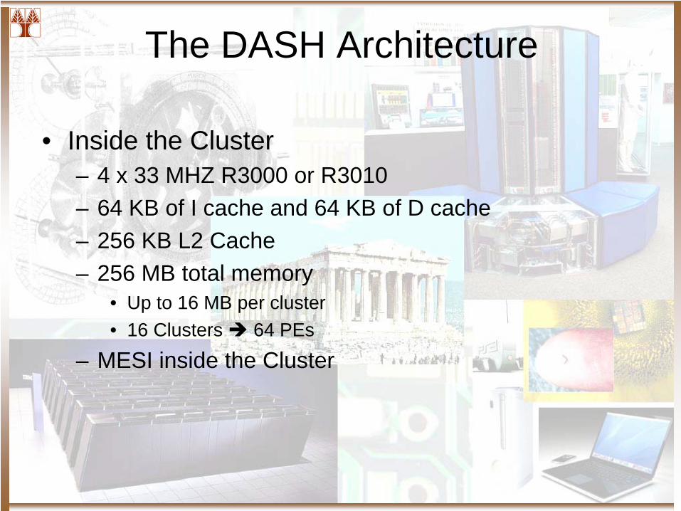
The DASH Architecture
• Inside the Cluster– 4 x 33 MHZ R3000 or R3010– 64 KB of I cache and 64 KB of D cache– 256 KB L2 Cache– 256 MB total memory
• Up to 16 MB per cluster• 16 Clusters 64 PEs
– MESI inside the Cluster
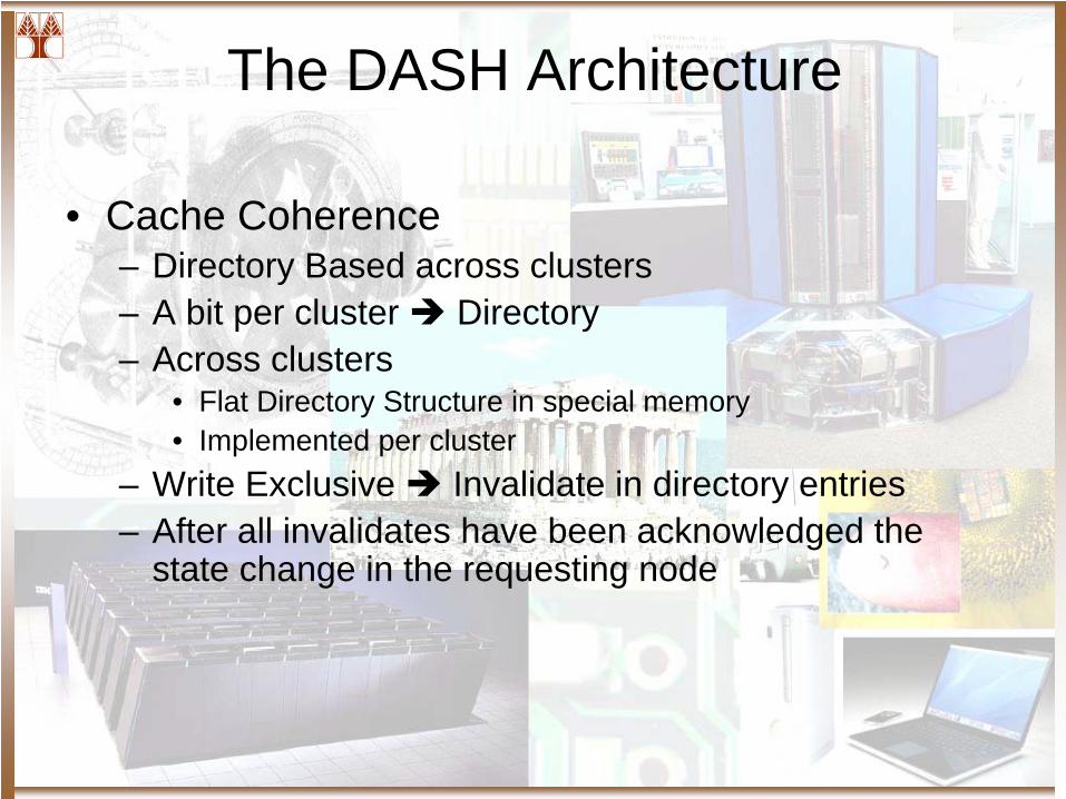
The DASH Architecture
• Cache Coherence– Directory Based across clusters– A bit per cluster Directory– Across clusters
• Flat Directory Structure in special memory• Implemented per cluster
– Write Exclusive Invalidate in directory entries– After all invalidates have been acknowledged the
state change in the requesting node
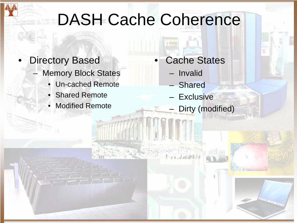
DASH Cache Coherence
• Directory Based– Memory Block States
• Un-cached Remote• Shared Remote• Modified Remote
• Cache States– Invalid– Shared – Exclusive– Dirty (modified)
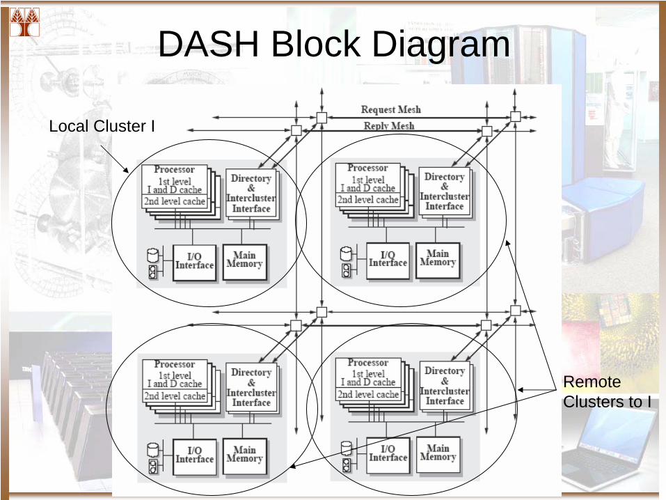
DASH Block Diagram
Local Cluster I
Remote Clusters to I
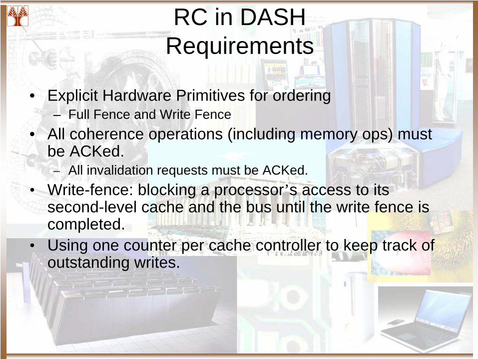
RC in DASH Requirements
• Explicit Hardware Primitives for ordering– Full Fence and Write Fence
• All coherence operations (including memory ops) must be ACKed.– All invalidation requests must be ACKed.
• Write-fence: blocking a processor’s access to its second-level cache and the bus until the write fence is completed.
• Using one counter per cache controller to keep track of outstanding writes.
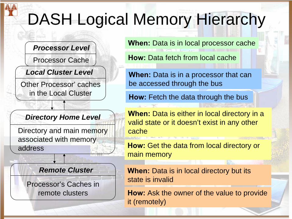
DASH Logical Memory HierarchyProcessor LevelProcessor Cache
Local Cluster LevelOther Processor’ caches
in the Local Cluster
Directory Home Level
Directory and main memory associated with memory address
Remote Cluster
Processor’s Caches in remote clusters
When:
Data is in local processor cache
How:
Data fetch from local cache
When:
Data is in a processor that can be accessed through the bus
How:
Fetch the data through the bus
When:
Data is either in local directory in a valid state or it doesn’t exist in any other cache
How:
Get the data from local directory or main memory
When:
Data is in local directory but its state is invalid
How:
Ask the owner of the value to provide it (remotely)
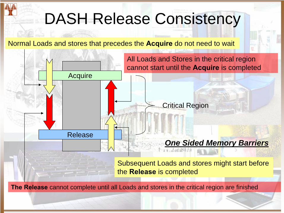
DASH Release Consistency
Acquire
Release
Critical Region
All Loads and Stores in the critical region cannot start until the Acquire
is completed
Subsequent Loads and stores might start before the Release
is completed
Normal Loads and stores that precedes the Acquire
do not need to wait
The Release cannot complete until all Loads and stores in the critical region are finished
One Sided Memory Barriers
DASH Other Features
• Software Controlled non-binding pre-fetching operations
• Atomic Read Modify Write Instructions• Un-cached locks, invalidating locks, granting
locks– Spinning in cached copy
• Fetch and Op– Increment and decrement in memory – Values are not cached

Scalable Global Address Space
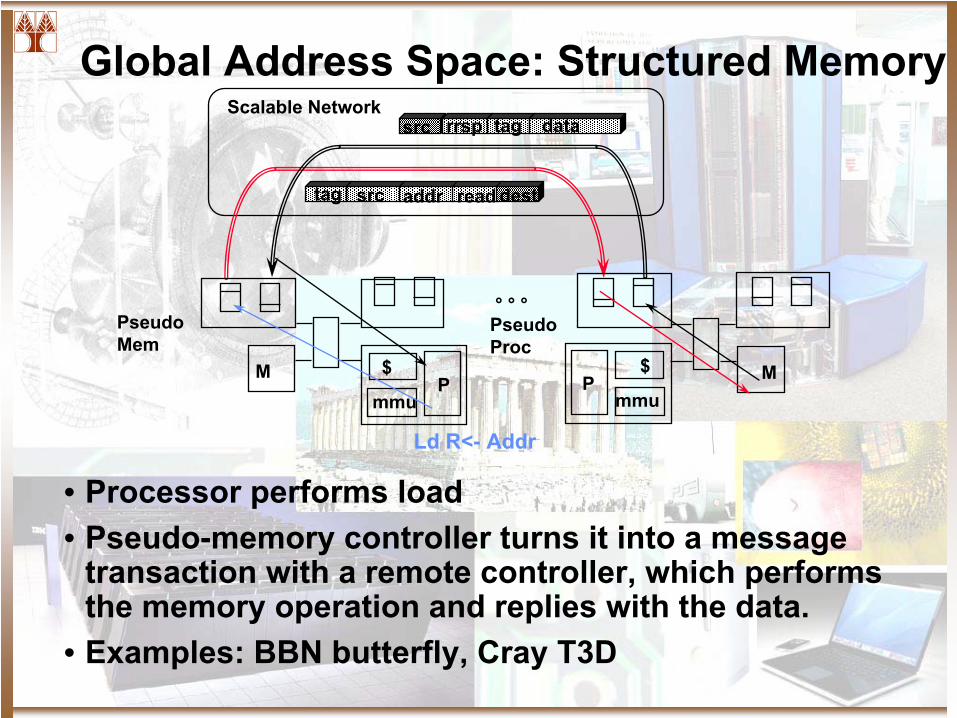
Global Address Space: Structured Memory
• Processor performs load• Pseudo-memory controller turns it into a message
transaction with a remote controller, which performs the memory operation and replies with the data.
• Examples: BBN butterfly, Cray T3D
src
° ° °
Scalable Network
M
PseudoMem
P$
mmuM
PseudoProc
readaddr desttag
src rrsp tag data
Ld R<-
Addr
P$
mmu
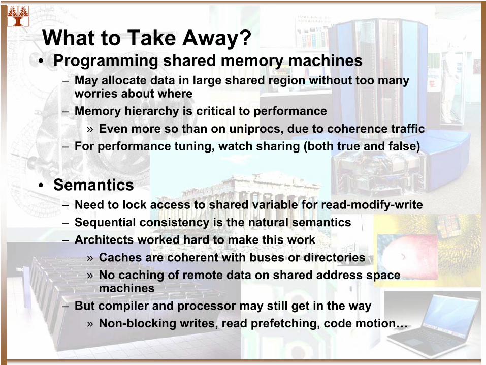
What to Take Away?• Programming shared memory machines
– May allocate data in large shared region without too many worries about where
– Memory hierarchy is critical to performance » Even more so than on uniprocs, due to coherence traffic
– For performance tuning, watch sharing (both true and false)
• Semantics– Need to lock access to shared variable for read-modify-write– Sequential consistency is the natural semantics– Architects worked hard to make this work
» Caches are coherent with buses or directories» No caching of remote data on shared address space
machines– But compiler and processor may still get in the way
» Non-blocking writes, read prefetching, code motion…
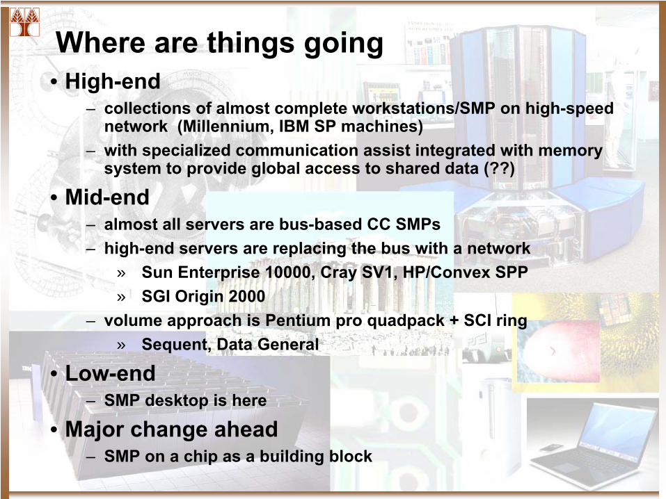
Where are things going• High-end
– collections of almost complete workstations/SMP on high-speed network (Millennium, IBM SP machines)
– with specialized communication assist integrated with memory system to provide global access to shared data (??)
• Mid-end– almost all servers are bus-based CC SMPs– high-end servers are replacing the bus with a network
» Sun Enterprise 10000, Cray SV1, HP/Convex SPP » SGI Origin 2000
– volume approach is Pentium pro quadpack
+ SCI ring» Sequent, Data General
• Low-end– SMP desktop is here
• Major change ahead– SMP on a chip as a building block
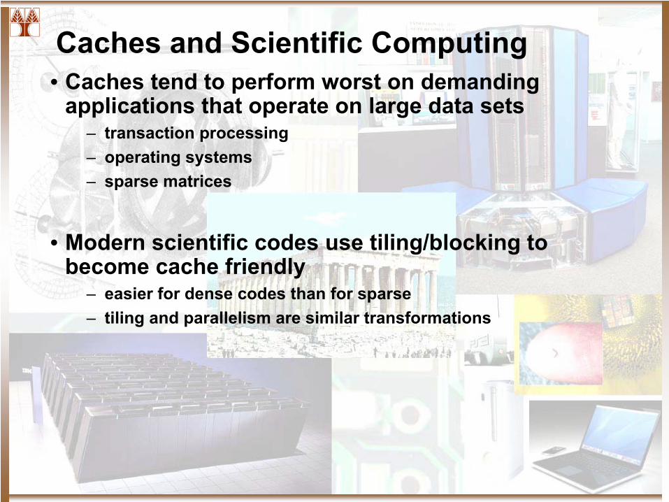
Caches and Scientific Computing• Caches tend to perform worst on demanding
applications that operate on large data sets– transaction processing– operating systems– sparse matrices
• Modern scientific codes use tiling/blocking to become cache friendly
– easier for dense codes than for sparse– tiling and parallelism are similar transformations
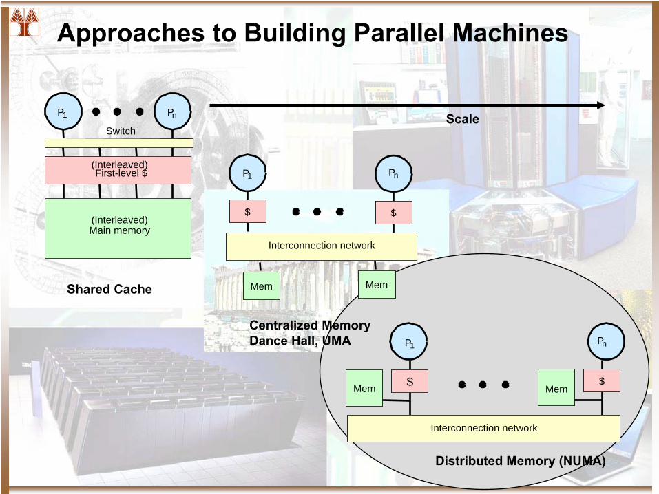
Approaches to Building Parallel Machines
P1
Switch
Main memory
Pn
(Interleaved)
(Interleaved)
First-level $
P1
$
Interconnection network
$
Pn
Mem Mem
P1
$
Interconnection network
$
Pn
Mem MemShared Cache
Centralized MemoryDance Hall, UMA
Distributed Memory (NUMA)
Scale
Distributed Shared Memory
Directory-Based Cache-Coherence
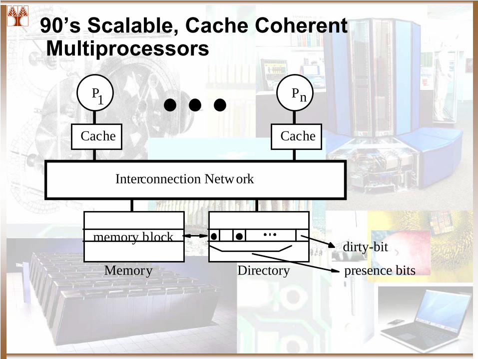
90’s Scalable, Cache Coherent Multiprocessors
P
Cache
P
Cache
Interconnection Network
Memory presence bits
dirty-bit
Directory
memory block
1 n
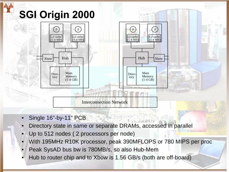
SGI Origin 2000
L2 cache
P
(1-4 MB)L2 cache
P
(1-4 MB)
HubXbow
Main Memory(1-4 GB)
Direc-tory
L2 cache
P
(1-4 MB)L2 cache
P
(1-4 MB)
Hub Xbow
Main Memory(1-4 GB)
Direc-tory
Interconnection Network
• Single 16”-by-11” PCB• Directory state in same or separate DRAMs, accessed in parallel• Up to 512 nodes ( 2 processors per node)• With 195MHz R10K processor, peak 390MFLOPS or 780 MIPS per proc• Peak SysAD bus bw is 780MB/s, so also Hub-Mem• Hub to router chip and to Xbow is 1.56 GB/s (both are off-board)
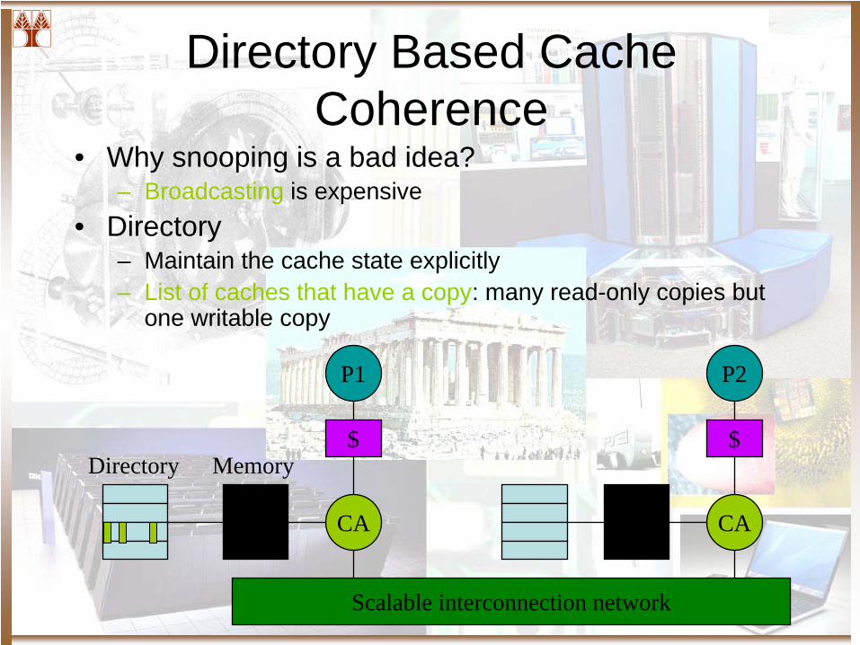
Directory Based Cache Coherence
• Why snooping is a bad idea?– Broadcasting is expensive
• Directory– Maintain the cache state explicitly– List of caches that have a copy: many read-only copies but
one writable copy
P1
$
CA
Scalable interconnection network
P2
$
CA
MemoryDirectory
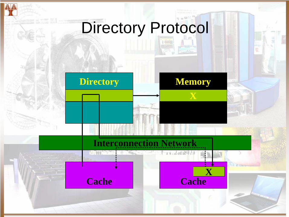
Directory Protocol
Directory MemoryX
Interconnection Network
Cache CacheX
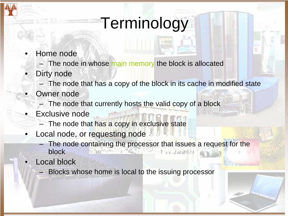
Terminology
• Home node– The node in whose main memory the block is allocated
• Dirty node– The node that has a copy of the block in its cache in modified state
• Owner node– The node that currently hosts the valid copy of a block
• Exclusive node– The node that has a copy in exclusive state
• Local node, or requesting node– The node containing the processor that issues a request for the
block• Local block
– Blocks whose home is local to the issuing processor
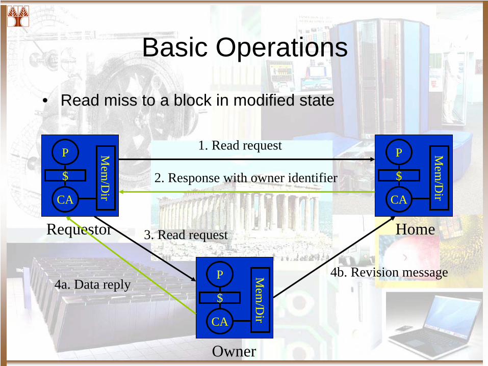
Basic Operations
• Read miss to a block in modified state
P
$
CA
Mem
/Dir
Requestor Home
Owner
P
$
CA
Mem
/Dir
P
$
CA
Mem
/Dir
1. Read request
2. Response with owner identifier
3. Read request
4a. Data reply4b. Revision message
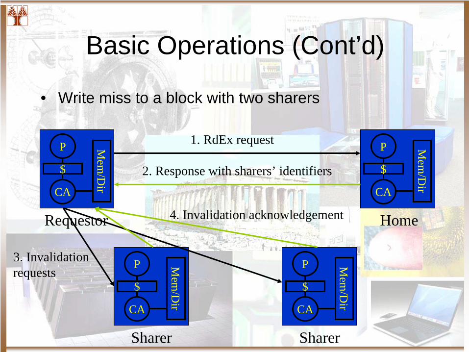
Basic Operations (Cont’d)
• Write miss to a block with two sharers
P
$
CA
Mem
/Dir
P
$
CA
Mem
/Dir
P
$
CAM
em/D
ir
P
$
CA
Mem
/Dir
Requestor Home
Sharer Sharer
1. RdEx request
2. Response with sharers’ identifiers
3. Invalidation requests
4. Invalidation acknowledgement
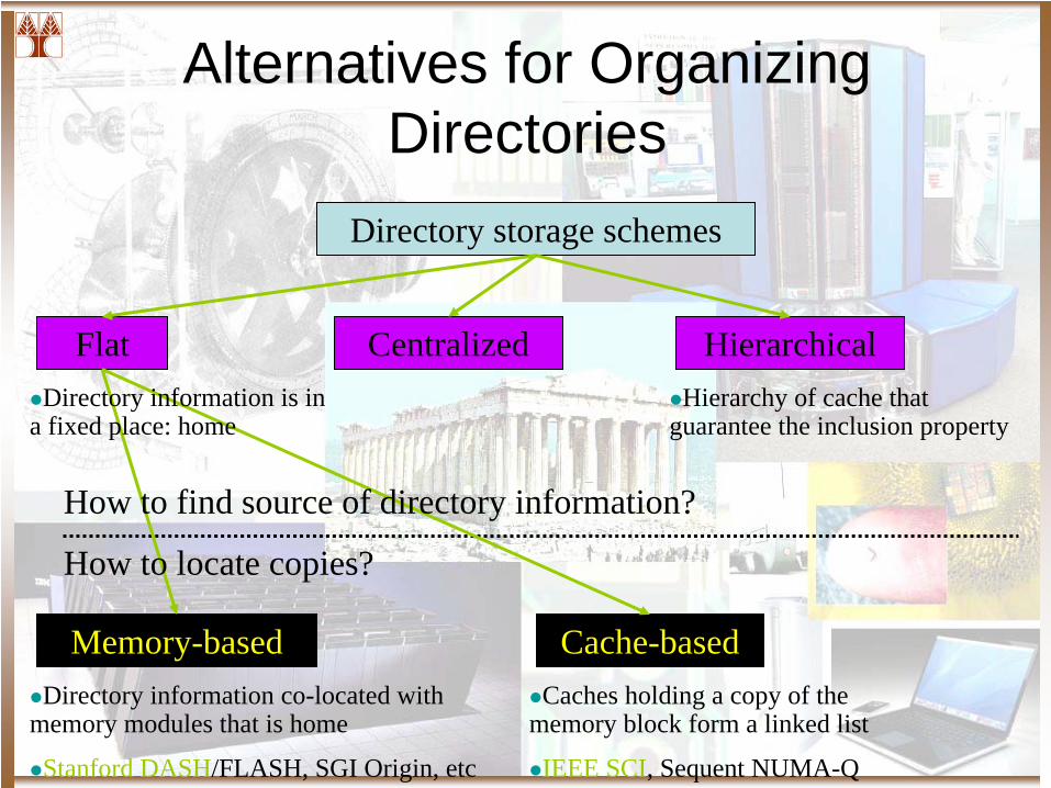
Alternatives for Organizing Directories
Directory storage schemes
Flat Centralized Hierarchical
Memory-based Cache-based
How to find source of directory information?
How to locate copies?
Directory information co-located with memory modules that is home
Stanford DASH/FLASH, SGI Origin, etc
Caches holding a copy of the memory block form a linked list
IEEE SCI, Sequent NUMA-Q
Directory information is in a fixed place: home
Hierarchy of cache that guarantee the inclusion property

Flat Directory Schemes
Full-Map DirectoryLimited DirectoryChained Directory
Memory-Based Directory Schemes
• Full bit vector (full-map) directory– Most straightforward – Low latency: parallel invalidation– Main disadvantage: storage overhead P*B
• Increase the cache block– Access time and network traffic increased due to false sharing
• Use hierarchical protocol: Stanford DASH: – Node has bus-based 4-processor
Storage Reducing Optimization: Directory Width
• Directory width– Bits per directory entry
• Motivation– Mostly only a few caches have a copy of a block
• Limited (pointer) directory– Storage overhead: log P * k (number of copies)– Overflow methods are needed– Diri
X• i indicates number of pointers (i < P)• X indicates invalidation methods: broadcast or non-broadcast
Overflow Methods for Limited Protocol
• Diri B (Broadcast)– Set the broadcast bit in case of overflow– Broadcast invalidation messages to all nodes– Simple– Increase write latency– Wasting communication bandwidth
• Diri NB (Not Broadcast)– Invalidate the copy of one sharer– Bad for widely shared read-mostly data– Degradation for intensive sharing of read-only and
read-mostly data due to increased miss ratio
Overflow Methods for Limited Protocol (Cont’d)
• Diri CVr (Coarse Vector)– Representation changes to a coarse bit vector
• If P <= i, i pointers• If P > i, each bit stands for a region of r processors (coarse
vector)
– Invalidations to the regions of caches– SGI Origin– Robust to different sharing patterns– 70% less memory message traffic than broadcast and
at least 8% less than other schemes
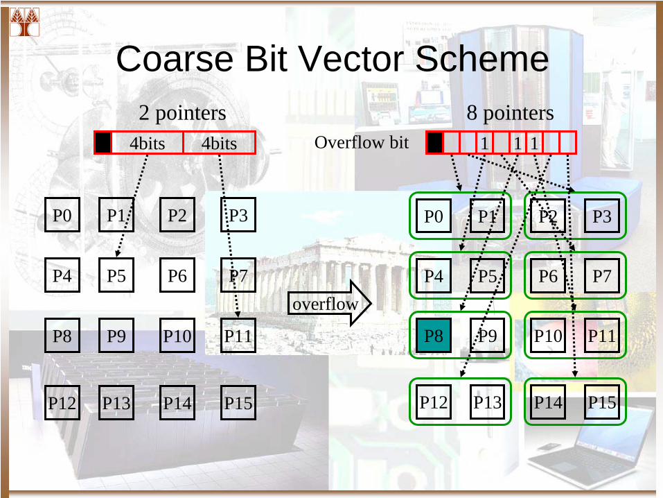
Coarse Bit Vector Scheme
P0 P1 P2 P3
P4 P5 P6 P7
P8 P9 P10 P11
P12 P13 P14 P15
0 4bits 4bits Overflow bit
overflow
1 1 1 1
P0 P1 P2 P3
P4 P5 P6 P7
P8 P9 P10 P11
P12 P13 P14 P15
2 pointers 8 pointers
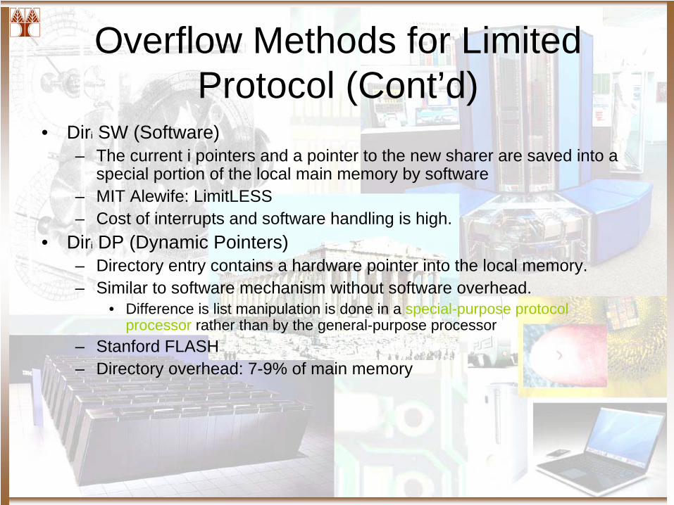
Overflow Methods for Limited Protocol (Cont’d)
• Diri SW (Software)– The current i pointers and a pointer to the new sharer are saved into a
special portion of the local main memory by software – MIT Alewife: LimitLESS– Cost of interrupts and software handling is high.
• Diri DP (Dynamic Pointers)– Directory entry contains a hardware pointer into the local memory.– Similar to software mechanism without software overhead.
• Difference is list manipulation is done in a special-purpose protocol processor rather than by the general-purpose processor
– Stanford FLASH– Directory overhead: 7-9% of main memory
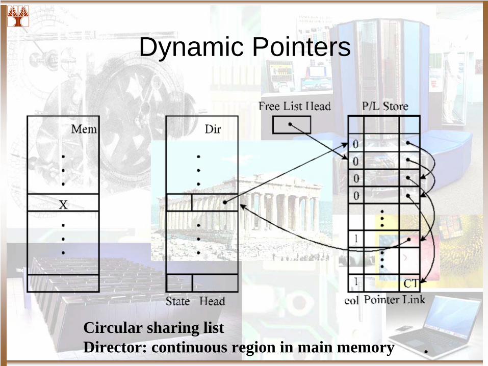
Dynamic Pointers
Circular sharing listDirector: continuous region in main memory
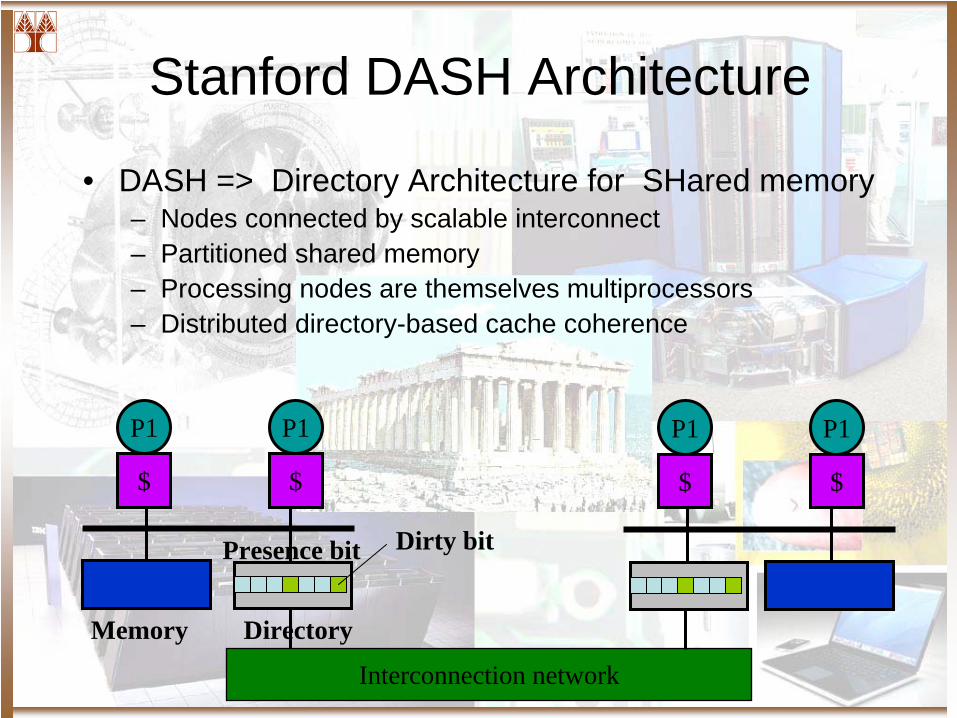
Stanford DASH Architecture
• DASH => Directory Architecture for SHared memory– Nodes connected by scalable interconnect– Partitioned shared memory– Processing nodes are themselves multiprocessors– Distributed directory-based cache coherence
Interconnection network
P1
$
P1
$
Memory Directory
Dirty bitPresence bit
P1
$
P1
$
Conclusions
• Full map is most appropriate up to a modest number of processors
• Diri CVr , Diri DP are most likely candidates– Coarse vector: lack of accuracy on overflow– Dynamic pointer: processing cost due hardware list
manipulation
Storage Reducing Optimization: Directory Height
• Directory height– Total number of directory entries
• Motivation– The total amount of cache memory is much less than the total main
memory• Sparse directory
– Organize the directory as a cache– This cache has no need for a backing store
• When an entry is replaced, send invalidations to the nodes with copies– Spatial locality is not an issue: one entry per block– References stream is heavily filtered, consisting of only those
references that were not satisfied in the processor caches.– With directory size factor = 8, associativity of 4, and LRU
replacement: very close to that of full-map directory
Protocol Optimization
• Two major goals + one – Reduce the number of network transactions per
memory operation• Reduce the bandwidth demand
– Reduce the number of actions on the critical path• Reduce the uncontended latency
– Reduce the endpoint assist occupancy per transaction
• Reduce the uncontended latency as well as endpoint contention
Hierarchical Coherence
Snoop-Snoop System
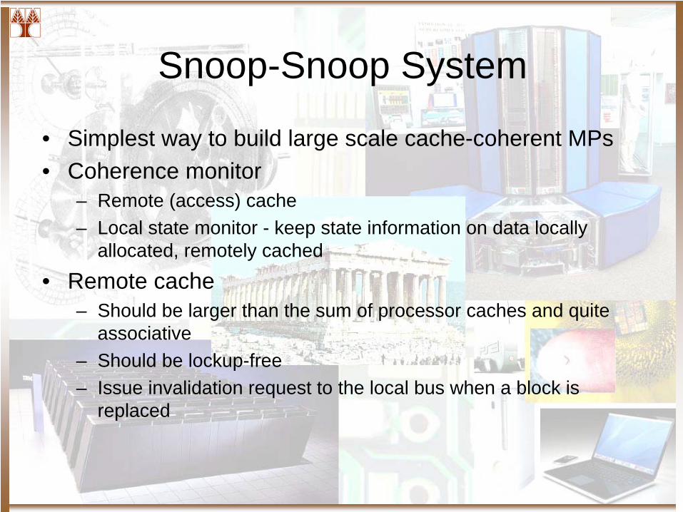
• Simplest way to build large scale cache-coherent MPs• Coherence monitor
– Remote (access) cache– Local state monitor - keep state information on data locally
allocated, remotely cached
• Remote cache– Should be larger than the sum of processor caches and quite
associative– Should be lockup-free– Issue invalidation request to the local bus when a block is
replaced
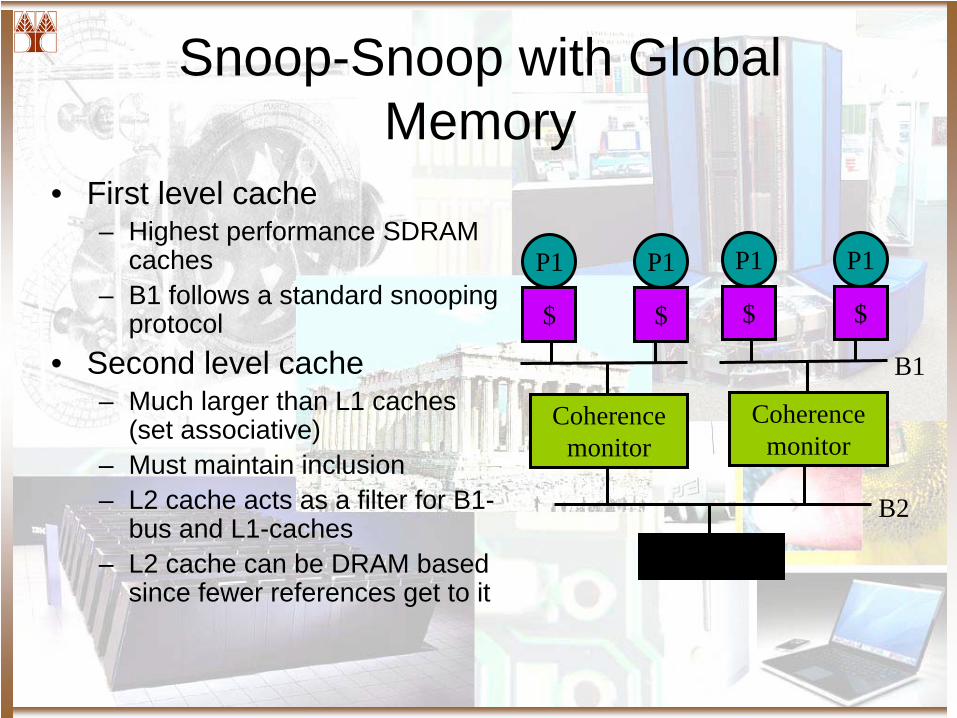
Snoop-Snoop with Global Memory
• First level cache– Highest performance SDRAM
caches– B1 follows a standard snooping
protocol• Second level cache
– Much larger than L1 caches (set associative)
– Must maintain inclusion– L2 cache acts as a filter for B1-
bus and L1-caches– L2 cache can be DRAM based
since fewer references get to it
B2
M
P1
$
P1
$
Coherence monitor
P1
$
P1
$
Coherence monitor
B1
Snoop-Snoop with Global Memory (Cont’d)
• Advantages– Misses to main memory just require single traversal to
the root of the hierarchy.– Placement of shared data is not an issue.
• Disadvantages– Misses to local data structures (e.g., stack) also have
to traverse the hierarchy, resulting in higher traffic and latency.
– Memory at the global bus must be highly interleaved. Otherwise bandwidth to it will not scale.
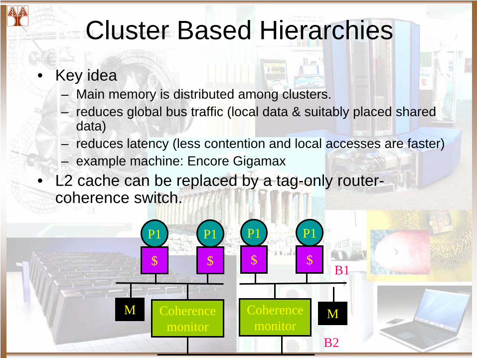
Cluster Based Hierarchies• Key idea
– Main memory is distributed among clusters.– reduces global bus traffic (local data & suitably placed shared
data)– reduces latency (less contention and local accesses are faster)– example machine: Encore Gigamax
• L2 cache can be replaced by a tag-only router- coherence switch.
B2
M
P1
$
P1
$
Coherence monitor
P1
$
P1
$
Coherence monitor
B1
M
Summary
• Advantages:– Conceptually simple to build (apply snooping
recursively)– Can get merging and combining of requests in
hardware• Disadvantages:
– Physical hierarchies do not provide enough bisection bandwidth (the root becomes a bottleneck, e.g., 2-d, 3-d grid problems)
– Latencies often larger than in direct networks
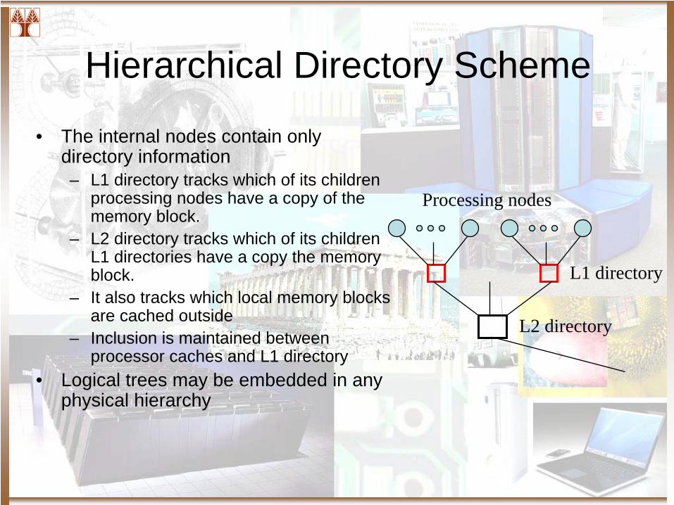
Hierarchical Directory Scheme
• The internal nodes contain only directory information– L1 directory tracks which of its children
processing nodes have a copy of the memory block.
– L2 directory tracks which of its children L1 directories have a copy the memory block.
– It also tracks which local memory blocks are cached outside
– Inclusion is maintained between processor caches and L1 directory
• Logical trees may be embedded in any physical hierarchy
L1 directory
L2 directory
Processing nodes
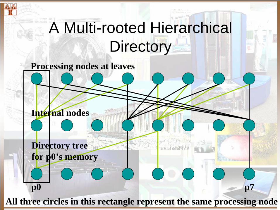
A Multi-rooted Hierarchical Directory
p0 p7
Directory tree for p0’s memory
Internal nodes
Processing nodes at leaves
All three circles in this rectangle represent the same processing node
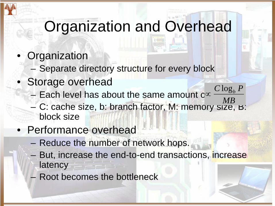
Organization and Overhead
• Organization– Separate directory structure for every block
• Storage overhead– Each level has about the same amount of memory– C: cache size, b: branch factor, M: memory size, B:
block size • Performance overhead
– Reduce the number of network hops. – But, increase the end-to-end transactions, increase
latency– Root becomes the bottleneck
MBPC blog
∝
Performance Implication of Hierarchical Coherence
• Advantages– Combining of requests for a block
• Reduce traffic and contention
– Locality effect• Reduce transit latency and contention
• Disadvantages– Long uncontended latency– Bandwidth requirements near the root of the hierarchy
Case Study
An Overview of Power PC Architecture
IBM PowerPC
• A weak consistency memory model machine.• A family of machines that supports visible cache
instructions and coherence / consistency checking.
• Found on the IBM server Family as well as the Apple Family of computers (with some modifications)
• Harvard Style Caches
PowerPC Consistency Instructions
• Data Cache Related Instructions– The dcb(f|st|i|t|tst|z)[e] instructions
• Instruction Cache Related instructions– The icbi[e] and isync instructions
• Memory Related Instructions– The mbar, msync, lwarx[e], and stwcrx[e] instructions
• TLB Related Instructions– The tlbsync instruction.
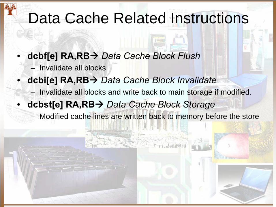
Data Cache Related Instructions
• dcbf[e] RA,RB Data Cache Block Flush– Invalidate all blocks
• dcbi[e] RA,RB Data Cache Block Invalidate– Invalidate all blocks and write back to main storage if modified.
• dcbst[e] RA,RB Data Cache Block Storage– Modified cache lines are written back to memory before the store
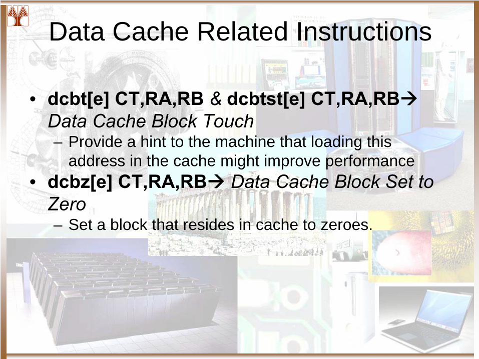
Data Cache Related Instructions
• dcbt[e] CT,RA,RB &
dcbtst[e] CT,RA,RBData Cache Block Touch– Provide a hint to the machine that loading this
address in the cache might improve performance• dcbz[e] CT,RA,RB Data Cache Block Set to
Zero– Set a block that resides in cache to zeroes.
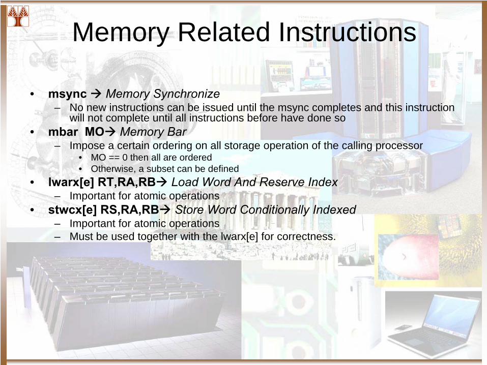
Memory Related Instructions
• msync Memory Synchronize– No new instructions can be issued until the msync completes and this instruction
will not complete until all instructions before have done so• mbar MO Memory Bar
– Impose a certain ordering on all storage operation of the calling processor • MO == 0 then all are ordered• Otherwise, a subset can be defined
• lwarx[e] RT,RA,RB Load Word And Reserve Index– Important for atomic operations
• stwcx[e] RS,RA,RB Store Word Conditionally Indexed– Important for atomic operations– Must be used together with the lwarx[e] for correctness.
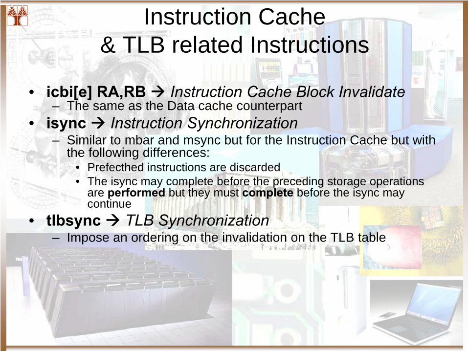
Instruction Cache & TLB related Instructions
• icbi[e] RA,RB Instruction Cache Block Invalidate– The same as the Data cache counterpart
• isync Instruction Synchronization– Similar to mbar and msync but for the Instruction Cache but with
the following differences:• Prefecthed instructions are discarded• The isync may complete before the preceding storage operations
are performed but they must complete
before the isync may continue
• tlbsync TLB Synchronization– Impose an ordering on the invalidation on the TLB table
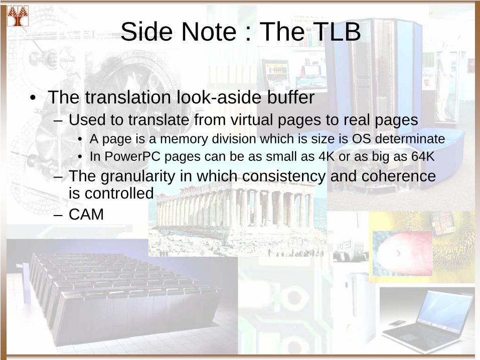
Side Note : The TLB
• The translation look-aside buffer– Used to translate from virtual pages to real pages
• A page is a memory division which is size is OS determinate• In PowerPC pages can be as small as 4K or as big as 64K
– The granularity in which consistency and coherence is controlled
– CAM
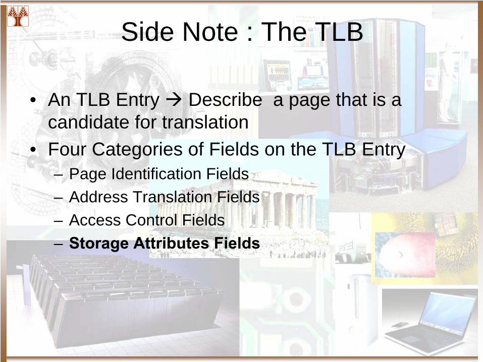
Side Note : The TLB
• An TLB Entry Describe a page that is a candidate for translation
• Four Categories of Fields on the TLB Entry– Page Identification Fields– Address Translation Fields– Access Control Fields– Storage Attributes Fields
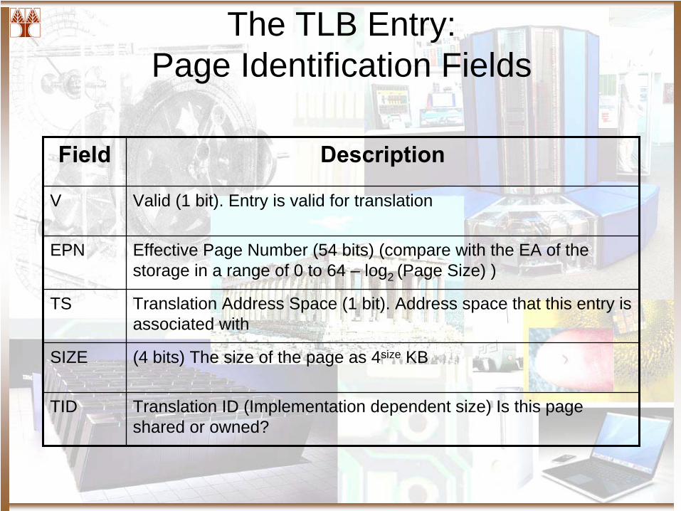
The TLB Entry: Page Identification Fields
Field Description
V Valid (1 bit). Entry is valid for translation
EPN Effective Page Number (54 bits) (compare with the EA of the storage in a range of 0 to 64 – log2 (Page Size) )
TS Translation Address Space (1 bit). Address space that this entry is associated with
SIZE (4 bits) The size of the page as 4size KB
TID Translation ID (Implementation dependent size) Is this page shared or owned?
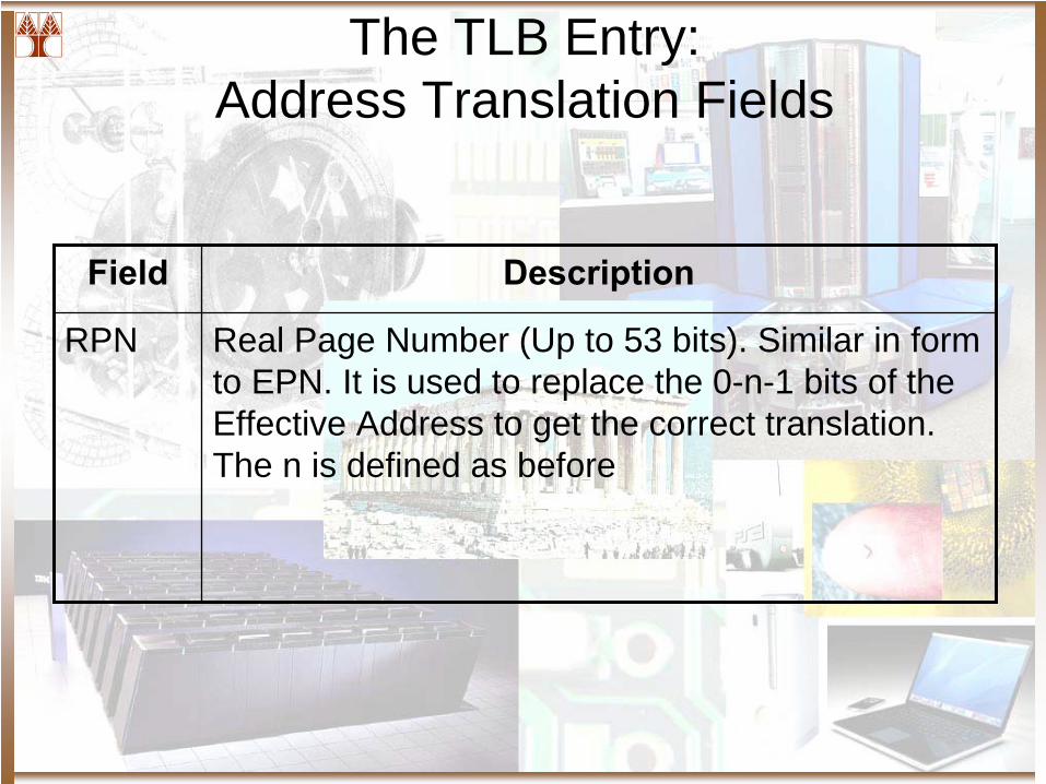
The TLB Entry: Address Translation Fields
Field Description
RPN Real Page Number (Up to 53 bits). Similar in form to EPN. It is used to replace the 0-n-1 bits of the Effective Address to get the correct translation. The n is defined as before
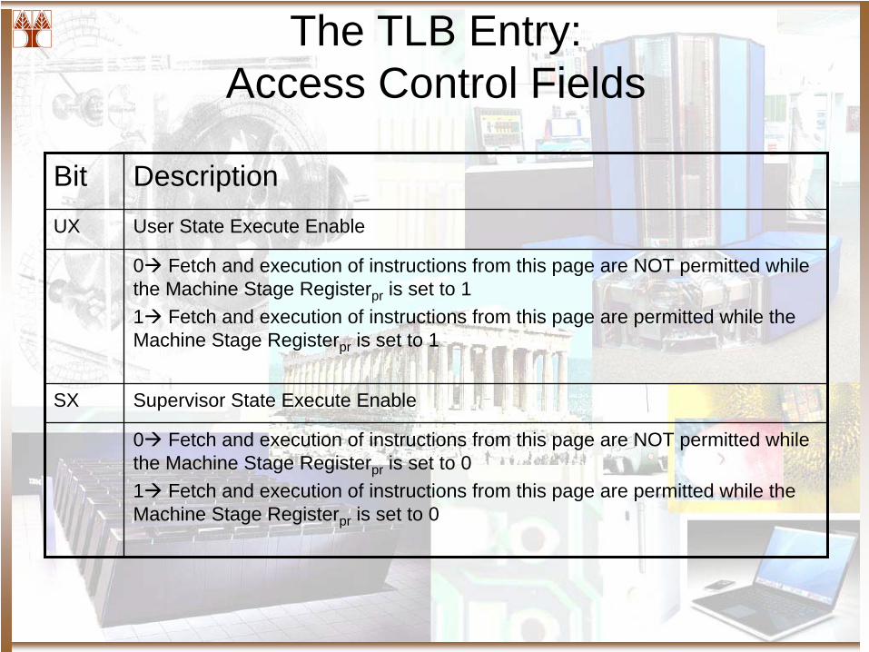
The TLB Entry: Access Control Fields
Bit DescriptionUX User State Execute Enable
0 Fetch and execution of instructions from this page are NOT permitted while the Machine Stage Registerpr is set to 11 Fetch and execution of instructions from this page are permitted while the Machine Stage Registerpr is set to 1
SX Supervisor State Execute Enable
0 Fetch and execution of instructions from this page are NOT permitted while the Machine Stage Registerpr is set to 01 Fetch and execution of instructions from this page are permitted while the Machine Stage Registerpr is set to 0
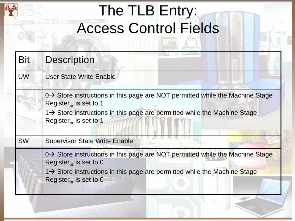
The TLB Entry: Access Control Fields
Bit DescriptionUW User State Write Enable
0 Store instructions in this page are NOT permitted while the Machine Stage Registerpr is set to 11 Store instructions in this page are permitted while the Machine Stage Registerpr is set to 1
SW Supervisor State Write Enable
0 Store instructions in this page are NOT permitted while the Machine Stage Registerpr is set to 01 Store instructions in this page are permitted while the Machine Stage Registerpr is set to 0
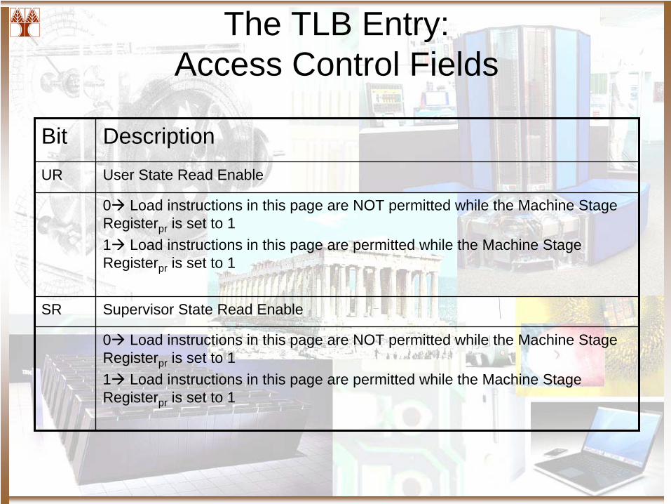
The TLB Entry: Access Control Fields
Bit DescriptionUR User State Read Enable
0 Load instructions in this page are NOT permitted while the Machine Stage Registerpr is set to 11 Load instructions in this page are permitted while the Machine Stage Registerpr is set to 1
SR Supervisor State Read Enable
0 Load instructions in this page are NOT permitted while the Machine Stage Registerpr is set to 11 Load instructions in this page are permitted while the Machine Stage Registerpr is set to 1
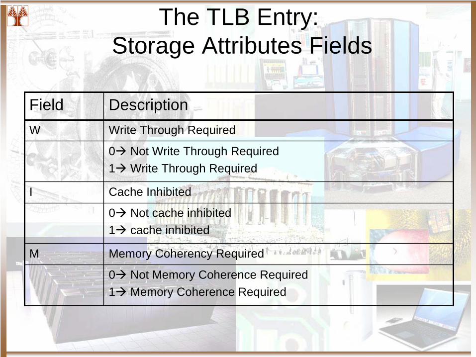
The TLB Entry: Storage Attributes Fields
Field DescriptionW Write Through Required
0 Not Write Through Required1 Write Through Required
I Cache Inhibited
0 Not cache inhibited1 cache inhibited
M Memory Coherency Required
0 Not Memory Coherence Required1 Memory Coherence Required
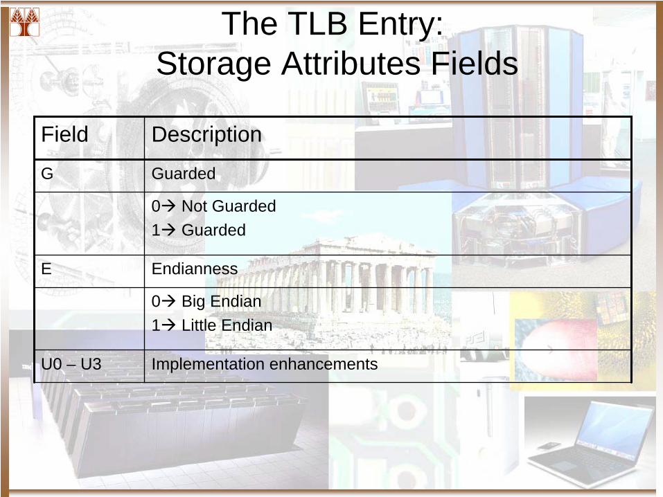
The TLB Entry: Storage Attributes Fields
Field Description
G Guarded
0 Not Guarded1 Guarded
E Endianness
0 Big Endian1 Little Endian
U0 – U3 Implementation enhancements
The TLB Entry: Storage Attributes Fields
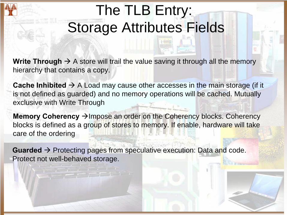
Write Through A store will trail the value saving it through all the memory hierarchy that contains a copy.
Cache Inhibited A Load may cause other accesses in the main storage (if it is not defined as guarded) and no memory operations will be cached. Mutually exclusive with Write Through
Memory Coherency Impose an order on the Coherency blocks. Coherency blocks is defined as a group of stores to memory. If enable, hardware will take care of the ordering
Guarded Protecting pages from speculative execution: Data and code. Protect not well-behaved storage.
Bibliography
• Mosberger, David. “Memory Consistency Models.” Department of Computer Science. University of Arizona. November 1993.
• Adve, Sarita; Gharachorloo, Kourosh. “Shared Memory Consistency Models: A Tutorial.” Rice University and DEC. IEEE Transactiona on Computers. 1996
• Lamport, Leslie. “How to Make a Multiprocessor Computer That Correctly Executes Multiprocess Programs.” IEEE Transactions on Computers, September 1979, pp.690-691
• “AMD64 Architecture Programmer’s Manual Volume 2: System Programming.”AMD64 Technology. September 2006
• Lenoski, et. Al. “The Stanford DASH Multiprocessor.” IEEE Computrer, 25(3): 63 – 69, March 1992